


 Loading...
MD CHANGER
KMD-300/GD2
SERVICE MANUAL
© 2003-11 CREATED IN JAPAN B53-0110-00 (N) 0
Audi GENUINE
GENUINE PARTS No.
Hardware |
4E0 |
035 121 41 |
Software |
4E0 |
910 121 0001 300 |
Panel assy (A64-2691-12)
Audi md changer
How to Take the Panel Assembly Off
1) Take the sheet (A) off. |
|
A |
2) Remove screw (B). |
|
|
|
B |
|
3) While pressing on the hook (C), take the panel |
|
C |
assembly off. |
|
|
|
|
|
|
C |
C |
|
|
B
C
BOTTOM
C 
C
2
J1 |
(X14-6912-70) |
(A/2) |
G&H |
|
|
GND |
1 |
|
BU+12V |
2 |
|
ID-X |
3 |
|
ID-Y |
4 |
|
DIAG |
5 |
|
|
6 |
|
|
7 |
|
|
8 |
|
IC3 6.5V IC2 5V DIG.
IC1 5V CONT.
MECHA CONNECTOR |
|
|
|
|
|
|
|
|
CN100 |
|
30 29 28 27 26 25 24 23 22 21 20 19 18 17 16 15 14 13 12 11 10 |
9 |
8 |
7 |
6 |
5 |
4 |
3 |
2 |
||
1 |
||||||||||
S +6.5V |
|
|
|
|
|
|
|
|
|
|
|
|
|
|
|
|
|
|
|
MCLK(22.5792MHz) |
|
|
|
|
|
|
|
|
|
D.AUDIO(IEC60958) |
||
M-BU+5V |
|
|
|
|
|
|
|
|
|
|
D+5V |
|
|
|
|
|
|
|
|
|
|
A+5V |
|
|
|
|
|
|
|
|
|
|
BU+5V |
|
|
|
|
|
|
|
|
|
|
(X25-9252-70)
IC30
BU. DET.
IC31
SW to
POW
Q41-43
DIAG
CIRCUIT
|
PON |
10 |
|
LEV6V |
|
|
LEV16V |
|
|
SW to POW |
|
IC32-34 |
|
|
POWER |
STATUS |
|
ON |
|
|
HOLD |
|
|
LOGIC |
|
|
DIAG IN |
|
|
|
|
|
|
DIAG OUT |
|
|
PINX |
|
|
PINY |
|
(X14- ) (B/2) |
|
|
|
|
|
|
|
|
|
||
|
|
|
|
|
|
|
|
|
|
|
D+5V |
|
LEDEJECT |
LEDDISC1 |
LEDDISC2 |
LEDDISC3 |
LEDGUIDE |
LEDLOAD |
DISC1SW |
DISC2SW |
DISC3SW |
EJECTSW |
6 |
|
LOADSW |
||||||||||
|
|
|
|
|
|
|
|
|
|
|
5 |
Q60-66 |
|
|
|
|
|
|
|
|
|
|
|
|
|
LED DRIVER |
|
|
|
|
|
|
|||
|
|
|
|
|
|
|
|
|
|
|
BU+5V |
STATUS
IC1
3.3V
PON LEV6V SW to PWR LEV16V STATUS HOLD DIAGIN DIAGOUT PINX PINY
IC90 |
|
WDTIMER |
|
|
IC30 |
WDTN |
RESET |
H8S2626 |
|
u-COM |
|
LED EJECT |
|
|
|
|
|
|
|
LED DISC1 |
|
|
|
|
|
|
|
LED DISC2 |
DISC1SW |
DISC2SW |
DISC3SW |
EJECTSW |
LOADSW |
CLEAR |
ATTOPT |
LED DISC3 |
|||||||
LED GUIDE |
|
|
|
|
|
|
|
LED LOAD |
|
|
|
|
|
|
|
|
IC70 |
|
SW EJECT |
KEY |
|
SW LOAD |
||
HOLD |
||
|
IC150 |
|
|
DIR |
|
|
|
|
IC151 |
DATAIN LRCIN |
CIN |
CL LRCL |
OS8104 |
|
|
MOST |
|
|
TRANCEIVER |
||
OPT ATT.
IC91
EEPROM
|
J180 |
|
MOST |
|
PIGTAIL |
8 |
RX |
7 |
STATUS |
6 |
GND |
5 |
BU+5V |
4 |
ATT |
3 |
D+5V |
2 |
GND |
1 |
TX |
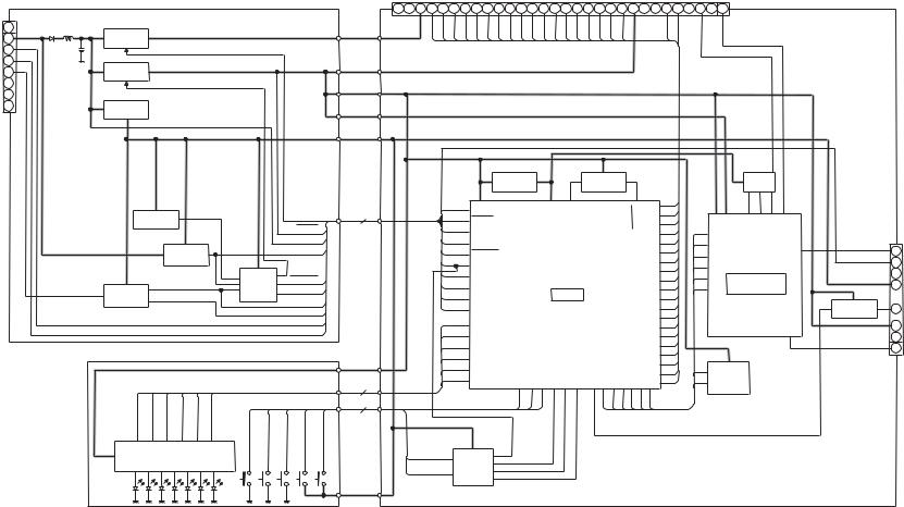
300/GD2-KMD DIAGRAM BLOCK
KMD-300/GD2
COMPONENTS DESCRIPTION
● DISPLAY UNIT (X14-6912-70)
Ref. No. |
Application/Function |
Operation /Condition/Compatibility |
|
|
|
IC1 |
Stabilized power supply |
Supplies Bu +5V to IC30, IC31, IC32, IC33, IC34, etc. |
|
|
|
IC2 |
Stabilized power supply |
Supplies D.+5V to X25 board |
|
|
|
IC3 |
Stabilized power supply |
Supplies +6.5V to mechanism X33 |
|
|
|
IC30 |
Reset IC |
OUT=H when BU+5V is above 4.2V |
|
|
|
IC31 |
1 pulse oscillation |
Oscillates 1 pulse at rise of BU |
|
|
|
IC32 |
NOT circuit |
((~STATUS | | DIAG | | Sw to Pow) &&-LEV6) | | HOLD=H, then D.+5V ON |
|
|
|
IC33 |
OR circuit |
((~STATUS | | DIAG | | Sw to Pow) &&-LEV6) | | HOLD=H, then D.+5V ON |
|
|
|
IC34 |
D flip-flop |
Detects downward slope of J1 DIAG |
|
|
|
Q1 |
Switch |
Q1 base =L, then LEV16=12V |
|
|
|
Q2 |
NOT circuit |
Q2 base =H, then Q1 base =L |
|
|
|
Q40 |
NOT circuit |
J1 DIAG=L, then IC33 A3 input=H |
|
|
|
Q41 |
NOT circuit |
CN1 DIAGOUT=H, then J1 DIAG=L |
|
|
|
Q42 |
Excess current protection |
Limit Q41 emitter current |
|
|
|
Q43 |
NOT circuit |
J1 DIAG=L, then CN1 DIAGIN=H |
|
|
|
Q60 |
Switch |
CN2 LED1=H, then D60 lights up. |
|
|
|
Q61 |
Switch |
CN2 LED2=H, then D61 lights up. |
|
|
|
Q62 |
Switch |
CN2 LED3=H, then D62 lights up. |
|
|
|
Q63 |
Switch |
CN2 LED4=H, then D63 lights up. |
|
|
|
Q64 |
Switch |
CN2 LED5=H, then D64 lights up. |
|
|
|
Q65 |
Switch |
CN2 LED6=H, then D65 lights up. |
|
|
|
Q66 |
Switch |
CN2 LED6=H, then D66 lights up. |
|
|
|
● ELECTRIC UNIT (X25-9252-70)
Ref. No. |
Application/Function |
Operation /Condition/Compatibility |
|
|
|
IC1 |
Stabilized power supply |
Supplies 3.3V to IC30 and IC150. |
|
|
|
IC30 |
-com |
Controls various sections of the set. |
|
|
|
IC70 |
D flip-flop |
Detects rise of key input for LOAD/EJECT |
|
|
|
IC71 |
NAND circuit |
IC70 CLR=~ (IC90 RESET&&IC30 CLEAR) |
|
|
|
IC90 |
RESET IC |
D+5V is above 4.2V, then RESET=H. |
|
|
|
IC91 |
EEPROM |
Saves backup data. |
|
|
|
IC150 |
DIR |
Converts IEC60958 (SPDIF) signal to 3-line serial. |
|
|
|
IC151 |
MOST transceiver |
Signal processing IC for optical input/output |
|
|
|
Q30 |
Switch |
PF3=L, then AVREF ON. |
|
|
|
Q70 |
NOT circuit |
CN70 EJECT=H, then IC30 EJECT=L |
|
|
|
Q71 |
NOT circuit |
CN70 LOAD=H, then IC30 LOAD=L |
|
|
|
Q180 |
NOT circuit |
MOST ATT=H, then Q181 base=L |
|
|
|
Q181 |
Switch |
MOST ATT=H, then increase optical output. |
|
|
|
3
KMD-300/GD2
MICROCOMPUTER’S TERMINAL DESCRIPTION
● MICROCOMPUTER : HD64F2626FA20I (X25 : IC30)
Pin No. |
Pin Name |
I/O |
Application |
|
|
|
|
1 |
ATT |
O |
MOST TX attenuate |
|
|
|
|
2 |
MOST_INT |
I |
MOST data reception interrupt |
|
|
|
|
3 |
BEEP |
O |
BEEP output |
|
|
|
|
4 |
ERROR |
I |
MOST error signal |
|
|
|
|
5 |
DIR_CS |
O |
DIR CS |
|
|
|
|
6 |
VCC1 |
|
|
|
|
|
|
7 |
HTxD |
|
|
|
|
|
|
8 |
VSS1 |
|
|
|
|
|
|
9 |
HRxD |
|
|
|
|
|
|
10 |
MMUTE |
I |
Mechanism mute detection |
|
|
|
|
11 |
SS1_SW |
I |
Stock1 Detection of disk/No disk SW |
|
|
|
|
12 |
SS2_SW |
I |
Stock2 Detection of disk/No disk SW |
|
|
|
|
13 |
SS3_SW |
I |
Stock3 Detection of disk/No disk SW |
|
|
|
|
14 |
MS_SW |
I |
EJECT complete detection SW |
|
|
|
|
15 |
VSS2 |
|
|
|
|
|
|
16 |
FS_SW |
I |
LOAD start detection SW |
|
|
|
|
17 |
PVCC1 |
|
|
|
|
|
|
18 |
OS_SW |
I |
Wrong direction detection SW |
|
|
|
|
19 |
NC |
|
|
|
|
|
|
20 |
MSTOP |
O |
Mechanism control Wake Up |
|
|
|
|
21 |
MRST |
O |
Mechanism control RESET |
|
|
|
|
22 |
M0 |
O |
M1, M2, M3 control output |
|
|
|
|
23 |
M1 |
O |
LO/EJ control output |
|
|
|
|
24 |
M2 |
O |
Mechanism roller attach control output |
|
|
|
|
25 |
M3 |
O |
Mechanism rising order control output |
|
|
|
|
26 |
NC |
|
|
|
|
|
|
27 |
NC |
|
|
|
|
|
|
28 |
MSDA |
I/O |
Mechanism I2C data |
|
|
|
|
29 |
MSCL |
I/O |
Mechanism I2C clock |
|
|
|
|
30 |
DIR_ERR |
I |
DIR error |
|
|
|
|
31 |
DIR_TX |
O |
DIR control output |
|
|
|
|
32 |
DIR_RX |
I |
DIR control input |
|
|
|
|
33 |
DIR_CLK |
O |
DIR clock |
|
|
|
|
34 |
SDA |
I/O |
MOST I2C data |
|
|
|
|
35 |
SCL |
I/O |
MOST I2C clock |
|
|
|
|
36 |
LED1 |
O |
MD1 eject SW LED |
|
|
|
|
37 |
VSS3 |
|
|
|
|
|
|
38 |
LED2 |
O |
MD2 eject SW LED |
|
|
|
|
39 |
PVCC2 |
|
|
|
|
|
|
40 |
LED3 |
O |
MD3 eject SW LED |
|
|
|
|
41 |
LED4 |
O |
Load SW LED |
|
|
|
|
42 |
LED5 |
O |
Eject SW LED |
|
|
|
|
43 |
LED6 |
O |
Insert slot LED |
|
|
|
|
44 |
CLEAR |
O |
Hard key buffer clear |
|
|
|
|
45 |
MOST_WRITE |
|
|
|
|
|
|
46 |
NC |
|
|
|
|
|
|
47 |
TXD |
O |
Flash writer data output |
|
|
|
|
48 |
RXD |
I |
Flash writer data input |
|
|
|
|
49 |
NC |
|
|
|
|
|
|
50 |
OSC1 |
|
|
|
|
|
|
4
KMD-300/GD2
MICROCOMPUTER’S TERMINAL DESCRIPTION
Pin No. |
Pin Name |
I/O |
Application |
|
|
|
|
51 |
OSC2 |
|
|
|
|
|
|
52 |
PVCC3 |
|
|
|
|
|
|
53 |
MD0 |
|
|
|
|
|
|
54 |
VSS4 |
|
|
|
|
|
|
55 |
MD1 |
I |
-com mode switching |
|
|
|
|
56 |
MD2 |
I |
-com mode switching |
|
|
|
|
57 |
PLLVSS |
|
|
|
|
|
|
58 |
PLLCAP |
|
|
|
|
|
|
59 |
PLLVCC |
|
|
|
|
|
|
60 |
RES |
I |
-com resetting |
|
|
|
|
61 |
NMI |
|
|
|
|
|
|
62 |
STBY |
|
|
|
|
|
|
63 |
VCC2 |
|
|
|
|
|
|
64 |
XTAL |
|
|
|
|
|
|
65 |
VSS5 |
|
|
|
|
|
|
66 |
EXTAL |
|
|
|
|
|
|
67 |
FEW |
I |
Flash write enable |
|
|
|
|
68 |
NC |
|
|
|
|
|
|
69 |
PON |
O |
Peripheral circuit power supply control |
|
|
|
|
70 |
SA_SW |
O |
SA switch |
|
|
|
|
71 |
HOLD_SW |
O |
SD switch |
|
|
|
|
72 |
LPSCO |
O |
Vref control |
|
|
|
|
73 |
WDT_OFF |
O |
Watch dog timer count output |
|
|
|
|
74 |
DIAG_OUT |
O |
DIAG output |
|
|
|
|
75 |
DIAG_IN |
I |
DIAG input |
|
|
|
|
76 |
AVCC |
|
|
|
|
|
|
77 |
Vref |
I |
Reference voltage input |
|
|
|
|
78 |
MLPS |
I |
Mechanism location position detection |
|
|
|
|
79 |
PS_SW |
I |
Play position detection of disk/No disk SW |
|
|
|
|
80 |
LS_SW |
I |
Load complete SW |
|
|
|
|
81 |
CS_SW |
I |
roller attach/detach SW |
|
|
|
|
82 |
BU_DET |
I |
Power supply +B input |
|
|
|
|
83 |
LEV16 |
I |
Power supply voltage detection |
|
|
|
|
84 |
NC |
|
|
|
|
|
|
85 |
LEV_6 |
I |
Power supply voltage <6V |
|
|
|
|
86 |
DISK1 |
I |
MD1 select SW |
|
|
|
|
87 |
DISK2 |
I |
MD2 select SW |
|
|
|
|
88 |
DISK3 |
I |
MD3 select SW |
|
|
|
|
89 |
LOAD |
I |
LOAD SW |
|
|
|
|
90 |
EJECT |
I |
Eject SW |
|
|
|
|
91 |
SW_TO_PW |
I |
Power supply control |
|
|
|
|
92 |
ID-X |
I |
Unit position detection |
|
|
|
|
93 |
ID-Y |
I |
Unit position detection |
|
|
|
|
94 |
AVSS |
|
|
|
|
|
|
95 |
VSS6 |
|
|
|
|
|
|
96 |
WDTOVFA |
|
|
|
|
|
|
97 |
PVCC4 |
|
|
|
|
|
|
98 |
NC |
|
|
|
|
|
|
99 |
STATUS |
|
MOST status |
|
|
|
|
100 |
MOST_RST |
|
MOST reset |
|
|
|
|
5

KMD-300/GD2
TEST MODE
1. TEST MODE
MDC possesses test mode functions for production purposes. There are three test modes: production line test mode, mechanism operation test mode, and shipping mode. As shown in Figure 1, it is possible by using the keys to shift to each of these modes.
|
|
Automatic |
|
|
mechanism |
|
|
mode |
Normal |
|
Test mode |
Operation |
|
|
|
for |
|
Mode |
|
|
|
mechanism |
|
|
|
|
|
|
operation |
e, w, q |
Manual |
|
Start |
|
mechanism |
|
|
mode |
q+e |
q, w, |
|
Test Mode |
e |
Production |
selection |
|
line |
mode |
|
Test Mode |
q, q, q
 Shipping
mode
1.1.2 How to exit the Test Mode selection mode
The following are ways to move out of the Test Mode selection mode. The operation after exiting the mode will be the same as after hardware resetting. The unit must be reset in the final stage of the Test Mode.
1.By resetting the system
2.By changing MOST Tx=On to MOST Tx=Off
3.By a momentary power outage
4.After entering this mode, when there is no effective key input for ten or more seconds
5.After entering this mode, when there is no ineffective key input
1.1.3 Initial condition after entering the Test Mode
The q, w, e, LOAD, and UNLOAD keys have LED’s (red and red only) installed.
Also, one LED (red and red only) is placed on each side of the disk insertion slot.
When the Test Mode selection mode is entered, all LED’s light up.
Figure 1 Test Mode conditioned flowchart
1.1. Test Mode selection mode
In this unit, there are but five keys: LOAD, UNLOAD, q (DISC SELECT LEFT KEY), w (DISC SELECT CENTER KEY), and e (DISC SELECT RIGHT KEY). After installation of the unit by the user, if direct switching to the Test Mode were enabled by combining these five keys, it is possible to shift accidentally into the Test Mode. This is because of the simplicity of the input method.
To avoid this problem, use Test Mode selection. This mode condition is achieved by enabling key input during the Test Mode. In other words, no direct switching to the Test Mode is done. This Test Mode selection mode prevents the user from entering the Test Mode inadvertently.
1.1.1 How to enter the Test Mode selection mode
With the MOST Tx Output (Light) on, by simultaneously depressing the q and e keys and by resetting or turning the power on, Test Mode selection mode is achieved.
Or with the MOST Tx Output (Light) off, by simultaneously depressing the q, e, and LOAD keys and resetting or turning the power on, the Test Mode selection mode is also achieved.
1.2. Shipping Mode
When transporting MD Changer units, their mechanisms are subject to vibrations and shocks. These could damage the MD Changer mechanisms (including the servo system and pickup). Therefore, before transporting the units, it is necessary to place the mechanisms in positions that are most vibration and shock resistant. The Shipping Mode causes the mechanism to shift into ideal, optimally robust shipping positions.
1.2.1 How to enter the Shipping Mode
In the Test Mode selection mode with no disk in the unit, the selection mode can be entered by pressing the q key three times.
1.2.2 How to exit the Shipping Mode
By resetting the system or by turning on the power, the Shipping Mode is released and the mechanism returns to its initial position.
Accordingly, after confirming that the mechanism has entered the Shipping Mode, the power should be turned off.
Table 1 MD Changer (Shipping Mode) Key description
Key Mode Description
#1 #1 #1 MD Changer Mechanism are put into shipping position.
6
KMD-300/GD2
TEST MODE
Table 2 Flow of MD Changer Conditions (Shipping Position)
Disk |
MD Changer Condition |
Display |
|
Condition |
|||
|
|
||
|
|
|
|
Out |
Receiving signal to shift |
#1 blinks with 500ms |
|
|
to shipping position |
interval |
|
|
|
|
|
|
Shifting |
#1 blinks with 500ms |
|
|
|
interval |
|
|
|
|
|
|
Shifting successfully |
#1 lights up |
|
|
completed. |
|
|
|
|
|
|
|
Shifting unsuccessful |
#1, #2, and #3 blink |
|
|
|
at 500ms intervals |
|
|
|
|
|
In |
Ineffective (any one of the |
|
|
|
switches of the mechanism |
|
|
|
is on). |
|
|
|
|
|
1.3. Production Line Test Mode
1.3.1 How to enter the production line Test Mode
In the Test Mode selection mode, with LED’s for the q, w, and e keys alight, it is possible to enter the production line Test Mode by consecutively pressing the q, w, and e keys. As these inputs are made, each LED on these keys lights up, enabling key input confirmation. Also, when the production line Test Mode is entered by effective key input, the LED’s that had remained unlit light up.
If incorrect keys were pressed or no effective key input were made for ten consecutive seconds, the Test Mode selection mode is released. In this case the Test Mode selection mode must be reentered to enable Test Mode entry.
1.3.2 How to enter the production line Test Mode
The following are ways to release the production line Test Mode selection mode. Ideally, the condition after exiting the Test Mode should be the same as after resetting the hardware by means of the program. This, however, cannot always be achieved at present.
Accordingly, it is necessary to reset the system in the final process of the Test Mode. (This excludes the case of setting the mechanism to transport position.)
1.By resetting the system
2.By changing MOST Tx=On to MOST Tx=Off
3.After entering the Test Mode, when an ineffective key was pressed
1.3.3 Initial condition in the production line Test Mode
In the Test Mode, there is no special initial setting. (This is other than the initial setting of normal units.) To indicate, however, that the Test Mode has been entered, all LED’s on the q, w, and e keys will light up.
1.3.4 Display (LED)
LED installation on the q, w, and e keys can be checked. With all disks removed, press any of the q, w, or e keys and lift your finger within one second. This causes the LED corresponding to the pressed key to go from “off” to “lighting up” to “blinking,” and to “off.”
When and if a disk or disks are present, the LED will light up according to the disk condition. (The condition according to normal operational specifications will follow.)
Inasmuch as the LED’s are also used for judging key input, no judgment results when there is a key-input problem. Accordingly, if no judgment were possible, a disk must be inserted into the desired position and appropriate key input made. Confirm that disk ejection is possible.
1.3.5 Keys
To ensure that the conductance of the q, w, e, LOAD, and UNLOAD keys is satisfactory, with all disks removed, press any of the q, w, e, LOAD, and UNLOAD keys and lift your finger within one second. Then confirm that the LED corresponding to the pressed key will proceed from “off” to “lighting up” to “blinking,” and to “off.”
Inasmuch as this is the same as evaluating the display (LED’s), if a problem exists with the LED, no evaluation can be conducted.
Accordingly, if no evaluation were possible, a disk must be placed into the desired position and appropriate key input made. Be sure that the disk can be ejected.
When and if the q, w, and e keys are depressed for more than one second, the Stock and Stock Position Confirmation Modes will be entered, as described below.
1.3.6 MD servo
After disk-loading, playing starts at Track No. 7.
The following key operations are begun by commands from the control unit and are conducted only when the source is the MD Changer.
Even when the playing track number is changed other than by the keys (commands) described below, the playing condition will persist.
1.3.7 Mechanism transport position
Refer to “1.2 Shipping Mode.”
To enter this mode, press the q key and hold it down one or more seconds.
7
KMD-300/GD2
TEST MODE
1.4 Test mode for MD Changer mechanism opera-
tion
1.4.1How to enter the Test Mode for MD Changer mechanism operation
After selecting the Test Mode selection mode, while the LED’s for the q, w, and e keys are lighting up, consecutively press the q, w, and e keys. The Test Mode for MD Changer mechanism operation can then be entered.
During key input, the LED corresponding to the key goes out, enabling key input confirmation.
After effective key input, when the Test Mode for the MD Changer mechanism operation is entered, all unlit LED’s will light up.
In case of an error in key input, or no effective key input were conducted for ten or more consecutive seconds, the Test Mode selection mode is released. It is then necessary to restart from the setting for the Test Mode selection mode.
Table 3 Test Mode input procedure for MD Changer mechanism operation
Procedure |
|
Key (result) / |
|||
Status and Operation |
LED (● light up) |
||||
and result |
|||||
|
|
|
|
||
|
q |
w |
e |
||
|
|
||||
|
|
|
|
|
|
1 |
In Test Mode selection mode |
- |
- |
- |
|
|
|
|
|||
● |
● |
● |
|||
|
|
||||
|
|
|
|
|
|
2 |
e key input |
7 |
7 |
3 |
|
|
|
|
|||
● |
● |
K |
|||
|
|
||||
|
|
|
|
|
|
3 |
w key input |
7 |
4 |
7 |
|
|
|
|
|||
● |
K |
K |
|||
|
|
||||
|
|
|
|
|
|
4 |
q key input |
5 |
7 |
7 |
|
|
|
|
|||
K |
K |
K |
|||
|
|
||||
|
|
|
|
|
|
5 |
Test Mode for MD Changer |
- |
- |
- |
|
mechanism operation |
|
|
|
||
● |
● |
● |
|||
|
|||||
|
|
|
|
|
|
6 |
Elapse of ten seconds |
7 |
7 |
7 |
|
|
|
|
|||
K |
K |
K |
|||
|
|
||||
|
|
|
|
|
|
7 |
Release of the Test Mode |
- |
- |
- |
|
selection mode |
|
|
|
||
K |
K |
K |
|||
|
|||||
|
|
|
|
|
|
1.4.2Releasing the Test Mode for MD Changer mechanism operation
The following methods release the Test Mode for MD Changer mechanism operation. Ideally, the condition after exiting the Test Mode should be the same as after resetting the hardware by means of the program. This, however, cannot always be achieved at present Below are ways to release the production line Test Mode selection mode.
The system must always be reset after the final process in the Test Mode. When, however, desiring to enter the transport position, simply shut off the power after confirming that the mechanism will shift into the transport position. Remember that, when resetting after shifting into the transport position, the unit will return to the initial position.
1.By resetting the system
2.After setting this mode, no effective key input is made for ten seconds.
3.After entering the Test Mode, an ineffective key was pressed.
1.4.3 Initial condition of the Test Mode for MD Changer
mechanism operation
There is no special initial setting in the Test Mode. Nevertheless, to indicate that the Test Mode has been entered, all LED's installed on theq, w, and e keys will light up.
8

1
2
3
4
5
6
7
A |
|
|
B |
|
|
C |
|
D |
|
E |
|
PC BOARD |
|
|
KMD-300/GD2 |
||||||||
|
|
|
|
|
|||||||
(COMPONENT SIDE VIEW) |
|
(FOIL SIDE VIEW) |
|
||||||||
|
ELECTRIC UNIT X25-9252-70 (J74-1528-12) |
|
ELECTRIC UNIT X25-9252-70 (J74-1528-12) |
|
|||||||
|
|
|
|
|
|
|
|
|
|
|
|
12 2 |
CN130 |
|
|
|
C185 |
|
8 |
|
|
|
|
|
|
|
|
1 |
|
|
|
||
|
|
|
|
|
|
|
|
|
|
|
|
|
|
|
|
|
|||
|
|
|
|
|
|
|
L157 |
|
|
C181 |
|
J180 |
C182 |
|
|
|
|||
|
|
|
|
|
|
|
|
|
|
|
|
|
|
|
|
|
|
||
|
|
|
|
|
|
|
|
|
|
|
|
|
|
|
|
|
|
|
|
|
|
|
R158 5 |
4R172 |
|
|
|
|
R180 |
|
|
|
|
|
|||||
|
|
L154 |
C165 |
1 |
L153 |
|
R155 |
|
EB |
|
|
|
|
||||||
|
|
|
|
|
|
|
|
|
|
|
|||||||||
C166 |
3 |
C187 |
|
|
|
R181 |
Q181 |
|
|
|
|||||||||
|
IC152 |
11 |
|
|
1 |
|
L152 |
|
|
Q180 |
|
|
|
|
|||||
|
|
|
|
|
12 |
|
|
|
|
44 |
|
|
BE |
|
|
|
CN1 |
|
|
|
|
|
|
|
|
|
|
|
|
|
|
|
|
|
C7 |
|
|||
|
|
|
C167 |
|
|
|
|
|
|
R171 |
|
|
|
||||||
|
|
|
|
|
|
|
|
|
|
CP2 |
C8 |
|
|
||||||
C169 |
|
|
|
IC151 |
|
R168 |
|
R169 |
R170 |
|
C9 |
|
|
||||||
|
|
|
C168 |
|
|
|
|
2 |
1 |
||||||||||
|
|
|
|
|
|
|
|
|
C11 |
||||||||||
|
|
|
|
|
|
|
|
|
|
|
|
|
|
C10 |
|
|
|||
|
|
|
|
|
22 |
|
|
|
|
34 |
|
|
|
|
|
CP1 |
C12 |
|
|
|
X150 |
C172 |
23 |
C173 |
R167 |
33 |
|
|
|
|
|
|
C13 |
|
|
||||
|
|
|
|
|
R165 |
|
|
|
|
|
|
|
C14 |
|
|
||||
|
|
|
|
R163 |
28 |
R154 |
C178 |
|
|
|
|
C160 |
R1 |
C15 |
|
|
|||
1 |
|
|
|
C177 |
L156 |
L1 |
|
|
|
||||||||||
C170 |
|
R164 |
C174 |
|
|
|
|
|
L3 |
|
|
||||||||
|
|
|
|
|
|
|
|
|
|
|
|
|
|
|
|
|
|
|
|
|
|
|
|
|
|
R153 |
|
C159 |
|
|
|
|
|
C1 |
|
|
|
||
|
|
|
|
|
|
|
|
|
|
|
|
|
C6 |
|
|
|
|||
|
|
|
|
IC150 |
|
CP151 |
|
|
|
|
|
|
|
|
|
|
|
||
|
|
|
|
|
|
|
|
|
|
|
|
|
|
C2 |
|
|
|
||
|
|
|
|
|
|
|
|
|
|
|
|
|
|
|
|
|
|
|
|
14 |
R150 |
|
|
15 L151 |
|
L150 |
|
|
L155 |
G |
|
I O |
48C19 |
47 |
|||||
R151 |
|
|
|
|
|
IC1 |
|||||||||||||
|
|
|
|
|
|
|
|
|
|
|
|
|
|
|
|
|
|
|
|
|
|
|
|
CP150 |
|
|
|
|
|
|
|
|
|
|
|
|
|
||
|
|
|
|
|
|
|
|
|
|
|
|
|
|
|
|
C17 |
|
|
|
|
|
|
|
|
|
D91 |
|
|
|
5 |
|
|
4 |
||
|
|
|
C90 |
|
|
|
|
|
IC91 |
|
|
||||
|
|
|
|
|
|
|
|
8 |
|
|
1 |
||||
|
|
|
9 |
|
|
|
8 |
|
|
|
|
|
|||
|
C93 |
|
|
|
|
|
|
C30 |
|
|
|
||||
|
|
|
|
|
|
|
|
|
|
|
|
||||
|
|
|
|
|
|
|
|
|
|
|
|
|
|
||
|
R91 |
|
IC90 |
|
|
|
|
|
|
|
|
|
|
||
|
R92 |
|
|
|
D34 |
|
|
|
C31 |
||||||
|
W90 |
16 |
|
|
|
|
|
|
|||||||
|
|
|
|
1 |
|
|
|
|
|
|
|
|
|||
|
R43 |
|
C94 |
|
|
|
|
|
|
|
|
|
|
|
|
R44 |
D30 |
|
D31 |
C38 |
C37 |
|
R35 |
|
|
||||||
|
|
|
|
R54 |
L30 |
|
|
||||||||
|
R45 |
|
|
|
|
W31 |
|||||||||
|
C44 |
R47 |
|
|
|
|
|
|
|
|
|
|
|||
|
|
|
|
|
|
|
|
|
|
|
|
|
|||
R46 |
|
R41 |
|
|
R40 |
R38 |
R36 |
|
|
R34 |
R33 |
||||
|
C46 |
C45 |
|
CP31 |
|
|
|
|
|
|
|
|
|
||
|
R48 |
|
51 |
50 |
|
|
|
|
|
|
26 |
25 |
|
||
|
C49 |
|
|
|
|
|
|
|
|
|
|
|
|
||
|
|
|
|
|
|
|
|
|
|
|
|
|
|
|
|
|
X30 |
|
|
|
|
IC30 |
|
|
|
|
|
|
|||
|
|
|
|
|
|
|
|
|
|
|
|
|
|
|
|
|
C50 |
|
75 |
|
|
|
|
|
|
|
|
|
|
1 R62 |
|
|
R52 |
R51 |
76 |
|
CP34 |
100 |
|
|
|||||||
R131 |
|
|
|
C53 |
|
|
|
|
|
||||||
R133 |
|
|
|
|
|
|
|
|
|
|
|
|
|
||
|
|
|
|
|
CP32 |
|
|
R57 |
R58 |
R59 |
R60 |
R61 |
|||
|
C131 |
|
|
|
|
|
|
||||||||
|
R135 |
|
|
|
|
|
|
|
|
|
|
|
|
|
|
11 1 |
R130 |
|
|
CP130 |
|
|
|
|
|
|
|
|
|
|
|
R132 |
|
1 |
14 |
|
|
|
|
|
|
|
BE |
||||
|
C133 |
|
|
|
|
D32 |
D33 Q30 |
||||||||
|
|
|
|
|
IC70 |
|
R56 |
C54 |
|
|
|
||||
|
R134 |
|
7 |
|
8 |
|
|
|
|
CP33 |
|||||
|
|
|
|
|
|
|
|
|
D72 |
|
|||||
|
|
|
|
|
|
|
|
L71 |
|
|
|
|
1 |
|
|
|
|
|
|
|
|
|
|
L72 |
|
|
|
|
|
|
|
|
|
|
|
|
|
|
|
L73 |
|
|
|
|
|
|
|
|
|
|
C100 |
C102 |
|
|
|
|
|
59 |
60 |
CP103 |
C125 |
|
|
C123 |
|
||
CP101CP102 |
C121 |
|
|
C119 |
|
||
|
C117 |
|
|
|
C115 |
|
|
CP100 |
C113 |
|
|
R103 |
|
||
|
C111 |
|
|
R102 |
L103 |
C105 |
|
R100 |
|
||
R101 |
|
|
|
|
|
1 |
2 |
|
L102 |
W100 |
CN100 |
L70 |
|
|
|
C82 |
|
|
|
CN70 |
|
14 |
|
|
C184 |
|
|
|
|
|
|
|
|
|
|
|
|
|
C189 |
C188 |
|
|
|
L183 |
|
|
C186 |
|
|
|
L182 |
|||||||||
|
|
|
|
|
|
|
|
|
|
|
|
|
|
|
|
|
|
|
|
|
|
|
|
|
|
|
|
|
|
|
||||||
|
C183 |
|
|
C180 |
|
|
|
|
|
C164 |
|
|
C163 |
|
|
|
|
|
|
R182 |
||||||||||||||||
|
L181 |
|
|
|
|
|
|
|
|
|
|
|
|
|
|
|
||||||||||||||||||||
|
|
|
|
|
|
|
|
|
|
|
|
|
|
|
|
|
|
|||||||||||||||||||
|
|
|
L180 |
|
|
|
|
|
|
|
|
|
C161 |
|
|
|
|
|
|
|
|
|
|
|||||||||||||
|
|
|
|
|
|
|
|
|
|
|
|
|
|
|
R173 |
|
|
|
|
R156 |
|
|
|
R159 |
||||||||||||
|
|
|
|
|
|
|
|
|
|
|
|
|
|
|
|
|
|
|
C162 |
|
R157 |
|
|
|
|
|
||||||||||
|
|
|
|
|
|
|
|
|
|
|
|
|
|
|
|
|
|
W152 |
R162 |
|
|
|
C171 |
|||||||||||||
|
|
|
|
|
|
|
|
|
|
|
|
|
|
|
|
|
|
|
|
|
||||||||||||||||
|
|
|
|
|
|
|
|
|
|
|
|
|
|
|
|
|
|
W154 |
|
|
|
|
|
|
|
|
|
|
|
|
|
|
|
|||
|
|
|
|
|
|
|
|
|
|
|
|
|
|
|
|
|
|
|
C175 |
|
|
|
|
|
|
|
|
|
|
|
|
|
|
|
||
|
|
|
|
|
|
|
|
|
|
|
|
|
|
|
|
|
|
|
C176 |
|
|
|
|
|
|
|
|
|
|
|
|
|
|
|
||
|
|
|
|
|
|
|
|
|
|
|
|
|
|
|
|
|
R166 |
|
|
|
|
|
|
|
|
|
D150 |
|||||||||
|
C3 |
|
|
|
|
|
|
|
|
|
|
|
|
|
|
|
|
|
|
|
|
|
|
|
|
|
|
|
|
|
|
|
|
|
||
|
|
|
|
|
|
|
|
|
|
|
|
|
|
|
|
|
|
|
|
|
|
|
|
|
|
|
|
|
|
|
|
|
|
|||
|
|
|
W2 |
|
|
|
|
|
|
|
|
|
|
|
|
|
|
|
|
|
|
|
|
|
|
|
|
|
|
|
|
|
|
|
|
|
|
|
|
|
|
|
|
|
C5 |
|
|
|
|
|
|
|
|
|
|
|
|
|
|
|
|
|
|
|
|
|
|
|
|
|
|
|
|
|
|
|
|
|
|
|
|
|
|
|
|
|
|
|
|
|
|
|
|
|
|
|
|
|
|
|
|
|
|
|
|
C151 |
||||
|
L2 |
|
C4 |
|
|
|
|
|
|
|
|
|
|
|
|
|
|
|
L160 |
|
|
C150 |
|
C157 |
||||||||||||
|
|
|
|
|
|
|
|
|
|
|
|
|
|
|
|
|
|
|||||||||||||||||||
|
|
|
|
|
|
|
|
|
|
|
|
|
|
|
|
|
|
|
|
|
|
|
|
|
|
|
|
|||||||||
|
|
|
|
|
|
|
|
D1 |
|
|
|
|
R2 |
|
|
|
|
L158 |
|
|
|
|
|
|
|
|
C153 |
|
C154 |
|||||||
C18 |
C16 |
|
|
|
|
|
|
|
|
|
|
|
|
|
|
|
L159 |
|
C156 |
|
|
|
|
|
||||||||||||
|
|
|
|
|
|
|
|
|
|
|
|
|
|
|
|
|
|
|
|
|
|
|
|
|
|
|
|
|
|
|
|
|
|
|||
|
|
|
|
|
|
|
|
|
|
|
|
|
|
|
|
|
|
|
|
|
|
|
|
|
|
|
|
|
|
|
|
|
|
|||
|
|
|
|
|
|
|
|
|
|
|
|
|
|
|
|
C95 |
|
|
|
|
R93 |
|
|
|
|
|
|
|
R90 |
|||||||
|
|
|
|
|
|
|
|
|
|
|
|
|
|
|
|
|
R94 |
|
|
|
|
|
|
|
|
|
|
|
|
|
|
|||||
L100 |
|
|
|
|
|
|
|
|
|
|
|
|
|
|
|
C96 |
C91 |
|
|
|
|
D90 |
|
|
|
|
|
|||||||||
|
|
|
|
|
|
|
|
|
|
|
|
|
|
|
|
|
|
|
|
|
|
|
||||||||||||||
C101 |
L101 |
|
|
|
|
|
|
|
|
|
|
|
|
|
|
|
|
|
C92 |
|
|
|
|
|
|
|
|
|
|
|||||||
|
|
|
|
|
|
|
|
|
|
|
|
|
|
|
|
|
|
|
|
|
|
|
|
|
|
|
||||||||||
|
C103 |
|
|
|
|
R30 |
|
|
|
R31 |
|
|
|
|
|
|
|
|
|
|
|
|
|
|
|
|
|
|
|
|||||||
|
|
|
|
|
|
|
|
|
|
|
|
|
|
|
|
|
|
|
|
|
|
|
|
|
|
|
||||||||||
|
|
|
|
|
|
|
|
|
|
|
|
|
|
|
|
|
|
|
|
|
|
|
|
|
|
|
||||||||||
|
|
|
|
|
|
|
|
|
|
|
|
|
|
|
|
|
|
|
|
|
|
|
|
|
|
|
|
|
|
|
|
|||||
|
|
|
|
|
|
|
|
|
|
|
|
|
|
|
|
|
|
|
|
|
|
|
|
|
|
|
|
|
|
|
|
|
|
|
||
|
C126 |
|
|
|
|
|
|
|
|
|
|
|
|
|
|
|
|
|
|
|
|
|
|
|
|
|
|
|
|
|
|
|
|
|
|
|
|
C124 |
|
|
|
|
|
|
|
|
|
|
|
|
|
C41 |
|
|
|
|
|
|
|
|
|
|
|
|
|
|
|
|
|
|
|
||
|
C122 |
|
|
|
|
|
|
|
|
|
|
|
|
|
|
|
|
|
|
|
|
|
|
|
|
|
|
|
|
|
|
|
|
|||
|
|
|
|
|
|
|
|
|
|
|
|
|
|
|
|
|
|
|
|
|
|
|
|
|
|
|
|
|
|
|
|
|||||
|
C120 |
|
|
|
C36 |
|
|
|
|
|
|
|
|
|
|
R37 |
R39 |
|
|
|
|
|
|
|
|
|
C43 |
|
|
|
|
|
||||
|
|
|
|
|
|
|
|
|
|
|
|
|
|
|
|
|
|
|
|
|
|
|
|
|
|
|
|
|||||||||
|
C118 |
|
|
|
|
|
|
|
|
|
|
|
|
|
|
|
|
|
|
|
|
|
|
|
|
|
|
|
||||||||
|
C116 |
|
|
|
|
|
|
|
|
|
|
|
|
|
|
|
|
|
|
|
|
|
|
|
|
|
C42 |
|
|
|
|
|
||||
|
|
|
|
|
|
|
|
|
|
|
|
|
|
|
|
|
|
|
|
|
|
|
|
|
|
|
|
|
|
|
|
|
|
|
||
|
|
|
|
|
|
|
|
|
|
|
|
|
|
|
|
C39 |
|
R49 |
|
|
|
|
|
R42 |
|
|
|
|
|
|||||||
|
C114 |
|
|
|
|
|
|
|
|
|
|
|
|
|
|
|
C40 |
|
|
|
|
|
|
|
|
|
|
|
||||||||
|
|
|
|
|
|
|
|
|
|
|
|
|
|
|
|
|
|
|
|
|
|
|
|
|
|
|
|
|
|
|
|
|
||||
|
C112 |
C35 |
|
C34 |
|
|
|
|
|
|
|
|
|
|
|
|
|
|
|
|
|
|
|
|
|
R50 |
||||||||||
|
|
|
|
|
|
|
|
|
|
|
|
|
|
|
|
|
|
C48 |
|
|
|
|||||||||||||||
|
C109 |
|
|
|
|
|
|
|
|
|
|
|
|
|
|
|
|
|
|
|
C47 |
|
|
|
|
|
||||||||||
|
C110 |
|
|
|
|
|
|
|
|
|
|
|
|
|
|
|
|
|
|
|
|
|
|
|
|
|
|
|
|
|
|
|
|
|
|
|
|
C108 |
|
|
|
|
|
C32 |
|
C33 |
|
|
|
|
|
R53 |
|
|
|
|
|
|
|
|
|
|
|
|
|
|
|
||||||
|
|
|
|
|
|
|
|
|
|
|
|
|
|
|
|
|
|
|
|
|
|
|
|
|
|
|
||||||||||
|
C107 |
|
|
|
|
|
|
|
|
|
|
|
|
|
|
|
|
|
|
|
|
|
|
|
|
|
|
|
|
|||||||
|
|
|
|
|
|
|
|
|
|
|
|
|
|
|
|
|
|
|
|
|
|
|
|
|
|
|
||||||||||
|
C106 |
|
|
|
R32 |
|
C55 |
|
C56 |
|
|
|
C52 |
|
|
|
|
|
|
|
|
|
|
|
|
|||||||||||
|
|
|
|
|
|
|
|
|
|
|
|
|
|
|
|
|
|
|
|
|
||||||||||||||||
|
|
|
|
|
|
|
|
|
|
|
|
|
|
|
|
|
|
|
|
|
|
|
|
R55 |
|
|
|
|
|
|||||||
|
C104 |
|
|
|
|
|
|
|
|
|
|
|
|
|
|
|
|
|
|
|
|
|
|
|
|
|
|
|
|
|
|
|
|
|
|
|
|
|
|
|
|
|
|
|
|
|
|
|
|
|
|
|
|
|
|
|
|
|
|
|
|
|
|
|
|
|
|
|
|
|
|
||
|
|
|
|
|
|
|
C51 |
|
|
C84 |
|
C85 |
|
|
|
|
|
|
|||||
|
|
C88 |
|||||
|
|
C87 |
|||||
IC71 |
1 |
|
5 |
|
|
|
|
|
|
|
|
||||
3 |
|
4 |
|
|
|
||
|
|
|
|
||||
C80 |
C81 |
|
|
Q70 |
|||
C78 |
C79 |
|
|
|
|
|
|
|
|
|
|
|
|||
C76 |
C77 |
D71 |
|||||
C74 |
C75 |
|
|
|
|
|
|
C73 |
C72 |
|
|
Q71 |
|||
C70 |
C71 |
|
|
|
|||
C139
C137
C135
C140
C132
C134
C138 R71 C136 C86 L130
C130
E B |
|
|
|
D70 |
|||
|
|
|
|
|
|||
|
|
|
|
R70 |
|||
|
|
|
|
||||
E B |
|
C83 |
|||||
|
|||||||
|
|||||||
|
|
|
|
|
|
|
|
X25-9252-70 |
|
|
|
|
X25-9252-70 |
|
|
|||
IC |
Q |
Address |
IC |
Q |
Address |
|
|
|||
|
IC |
Q |
Address |
|
||||||
|
|
|
|
|
|
|
|
|||
1 |
|
4B |
151 |
|
3B |
|||||
|
|
|
|
|
|
|
||||
|
|
|
71 |
|
6D |
|
||||
30 |
|
5B |
152 |
|
2A |
|
|
|
||
|
|
|
|
70 |
6D |
|
||||
70 |
|
6A |
|
30 |
5B |
|
|
|
||
|
|
|
|
71 |
6D |
|
||||
90 |
|
4B |
|
180 |
3B |
|
|
|
||
|
|
|
|
|
|
|
||||
91 |
|
4B |
|
181 |
2B |
|
|
|
|
|
150 |
|
3A |
|
|
|
Refer to the schematic diagram for the values of resistors and capacitors. |
||||
9
Loading...