


 Loading...
SERVICE MANUAL
DVD / HDD VIDEO RECORDER & VIDEO CASSETTE RECORDER
DR-MX1SEF, DR-MX1SEK, DR-MX1SEU, DR-MX1SEY, DR-MX1SEZ
CABLE/DBS
TV 


 DVD
DVD
VHS TV/ 
 STANDBY/ON
TIMER VIDEO TV/CBL/DBS DVD
VHS HDD DVD
|
|
|
TV VOLUME |
|
|
|
CH |
CANCEL |
AUX |
MEMO/MARK |
|
LIVE |
DUBBING |
EDIT |
PROGRAM |
TV MUTING |
|
|
|
TOP MENU |
|
NAVIGATION |
|
|
ENTER |
|
|
MENU |
|
|
RETURN |
PREVIOUS |
|
|
NEXT |
SLOW |
PLAY/SELECT |
SLOW |
|
REC |
STOP/ CLEAR |
PAUSE |
|
JUMP |
|
|
|
REC MODE |
DISPLAY |
ON SCREEN |
SET UP |
REMAIN |
|
|
|
|
|
|
|
STANDBY/ ON |
|
|
|
VHS/HDD/DVD |
|
|
|
|
|
|
|
|
|
|
|
SELECT |
|
|
|
|
|
|
REC LINK |
S-VIDEO |
VIDEO (MONO)L–AUDIO–R |
VRS – |
HDD – |
DVD – |
|
|
DV IN |
|
|
|
|
HDD/DVD |
|
CH |
|
DISPLAY |
VHS TIMER |
REC MODE |
|
|
|
|
|
|
|
|
|||||
AUDIO |
SUBTITLE |
ANGLE |
PROGRESSIVE |
|
|
|
|
|
|
|
|
SCAN |
|
|
F–1 |
|
|
|
|
|
|||
|
|
LIVE CHECK |
|
|
|
|
|
|
|
|
|
(EF model)
(EK model)
(EU,EY,EZ model)
(EF model)
DR-MX1SEF, DR-MX1SEK, DR-MX1SEU, DR-MX1SEY, DR-MX1SEZ [D4VC21]
For disassembling and assembling of MECHANISM ASSEMBLY, refer to the SERVICE MANUAL No.86700(MECHANISM ASSEMBLY).
TABLE OF CONTENTS
1 PRECAUTION. . . . . . . . . . . . . . . . . . . . . . . . . . . . . . . . . . . . . . . . . . . . . . . . . . . . . . . . . . . . . . . . . . . . . . . . . 1-3 2 SPECIFIC SERVICE INSTRUCTIONS . . . . . . . . . . . . . . . . . . . . . . . . . . . . . . . . . . . . . . . . . . . . . . . . . . . . . . 1-6 3 DISASSEMBLY . . . . . . . . . . . . . . . . . . . . . . . . . . . . . . . . . . . . . . . . . . . . . . . . . . . . . . . . . . . . . . . . . . . . . . . 1-9 4 ADJUSTMENT . . . . . . . . . . . . . . . . . . . . . . . . . . . . . . . . . . . . . . . . . . . . . . . . . . . . . . . . . . . . . . . . . . . . . . . 1-12 5 TROUBLESHOOTING . . . . . . . . . . . . . . . . . . . . . . . . . . . . . . . . . . . . . . . . . . . . . . . . . . . . . . . . . . . . . . . . . 1-18
COPYRIGHT © 2005 Victor Company of Japan, Limited
No.YD048
2005/1
SPECIFICATION
|
DR-MX1SEK |
|
DR-MX1SEU / EY / EZ |
|
|
DR-MX1SEF |
|
GENERAL |
|
|
|
|
|
|
|
Power requirement |
|
|
AC 220 V - 240 V, 50 Hz / 60 Hz |
|
|
||
Power consumption |
|
|
|
|
|
|
|
Power on |
|
|
47 W |
|
|
|
|
Power off |
|
|
16.6 W |
|
|
|
|
Temperature |
|
|
|
|
|
|
|
Operating |
|
|
5°C to 35°C° |
|
|
||
Storage |
|
|
-20°C to 60°C |
|
|
||
Operating position |
|
|
Horizontal only |
|
|
||
Dimensions (W × H × D) |
|
|
435 mm × 96 mm × |
383 mm |
|
|
|
Weight |
|
|
7.2 kg |
|
|
|
|
Input/Output |
|
|
|
|
|
|
|
Video input |
|
|
0.5 - 2.0 Vp-p, 75 Ω |
(pin jack) |
|
|
|
Audio input |
-8 dB, 50 kΩ (pin jack), Corresponding to mono (left) |
|
|||||
Audio output |
|
|
-8 dB, 1 kΩ (pin jack) |
|
|
||
21-pin SCART connectors |
|
|
IN / OUT × 1, IN / DECODER × 1 |
|
|
||
Input / Output (HDD & DVD Deck Only) |
|
|
|
|
|
||
S-video input |
Y: 0.8 - 1.2 Vp-p, 75 Ω , C: 0.2 - 0.4 Vp-p, 75 Ω |
|
|
||||
i.Link |
|
|
4-pin for DV input |
|
|
||
Component video output |
Y: 1.0 Vp-p, 75 Ω , CB/CR, PB/PR: 0.7 Vp-p, 75 Ω, Corresponding to copy protection |
||||||
SAT Control |
|
|
Ø3.5mm |
|
|
|
|
Digital audio output |
Optical: -18 dBm, 660 nm, Coaxial: 0.7 Vp-p, 75 Ω , Corresponding to Dolby Digital and DTS Digital Surround |
||||||
|
Bit stream Selectable in digital audio output setting menu |
|
|||||
VIDEO/AUDIO (DVD Deck) |
|
|
|
|
|
|
|
Recording time |
Maximum 8 hours (with 4.7 GB disc), (XP): Approx. 1 hour, (SP): Approx. 2 hours, |
(LP): Approx. 4 hours |
|||||
|
(EP): Approx. 6 hours, (FR): Approx. 1 hour - 8 hours |
|
|||||
Audio recording system |
Dolby Digital (2 ch), Linear PCM (XP mode only) |
|
|||||
Video recording compression system |
|
|
MPEG2 (CBR/VBR) |
|
|
||
VIDEO/AUDIO (HDD Deck) |
|
|
|
|
|
|
|
Video recording compression system |
|
|
MPEG2 (VBR) |
|
|
||
Audio recording system |
Dolby Digital (2 ch), Linear PCM (XP mode only) |
|
|||||
Recording time |
Maximum 300 hours (with 160 GB HDD), (XP): Approx. 34 hours, (SP): Approx. 69 hours, (LP): Approx. 138 hours |
||||||
|
(EP): Approx. 209 hours, (FR): Approx. 36 - 300 hours |
|
|||||
VIDEO/AUDIO (VHS Deck) |
|
|
|
|
|
|
|
Signal system |
PAL colour signal and CCIR monochrome signal, 625 lines / 50 fields |
|
PAL/SECAM colour signal and CCIR |
||||
|
|
monochrome signal, 625 lines/50 fields |
|||||
|
|
|
|
|
|
||
Recording system |
DA4 (Double Azimuth) head helical scan system |
|
|||||
Format |
VHS PAL standard |
|
|
|
VHS PAL/SECAM standard |
||
Tape width |
|
|
12.65 mm |
|
|
|
|
Tape speed |
|
|
|
|
|
|
|
(SP) |
|
|
23.39 mm/s |
|
|
||
(LP) |
|
|
11.70 mm/s |
|
|
||
Maximum recording time |
|
|
|
|
|
|
|
(SP) |
|
|
240 min. with E-240 video cassette |
|
|
||
(LP) |
|
|
480 min. with E-240 video cassette |
|
|
||
Signal-to-noise ratio |
|
|
45 dB |
|
|
|
|
Horizontal resolution |
|
|
230 lines |
|
|
|
|
Frequency range |
70 Hz to 10,000 Hz (Normal audio) 20 Hz to 20,000 Hz (Hi-Fi audio) |
||||||
TUNER/TIMER |
|
|
|
|
|
|
|
TV channel storage capacity |
|
|
99 positions (+AUX position) |
|
|
||
Tuning system |
|
|
Frequency synthesized tuner |
|
|
||
Channel coverage (PAL) |
|
|
|
|
|
VHF(LOW): 47MHz - 89MHz(E2 - |
|
|
VHF : 44.5 MHz - 143 MHz/143 MHz - 470 |
|
VHF : 47 MHz - 89 MHz/104 MHz - 300 |
|
E4,X,Y,Z) |
||
|
|
|
VHF(HIGH): 104MHz-300MHz(E5 - E12, |
||||
|
MHz |
|
MHz/302 MHz - 470 MHz |
|
|||
|
|
|
|
S1-S20, M1 - M10, U1 - U10) |
|||
|
UHF : 470 MHz - 862 MHz |
|
UHF : 470 MHz - 862 MHz |
|
|
|
|
|
|
|
|
Hyper: 302MHz - 470MHz (S21-S41) |
|||
|
|
|
|
|
|
||
|
|
|
|
|
|
UHF: 470MHz - 862MHz (E21 - E69) |
|
Channel coverage(SECAM-L) |
|
|
|
|
|
VHF(LOW): 49MHz - 65MHz (2-4) |
|
|
- |
|
|
|
VHF(HIGH): 104MHz - 300 MHz (5-10, |
||
|
|
|
|
CATV) |
|
||
|
|
|
|
|
|
Hyper : 300MHz - 470MHz (CATV) |
|
|
|
|
|
|
|
UHF : 470MHz - 862MHz (21 - 69) |
|
Memory backup time |
|
|
Approx. 60 minutes |
|
|
|
|
ACCESSORIES |
|
|
|
|
|
|
|
Provided accessories |
RF cable, 21-pin SCART cable, Satellite Controller, Infrared remote control unit, "AA(R6)" battery × 2 |
||||||
•Specifications shown are for SP mode unless otherwise specified.
•E.& O.E. Design and specifications subject to change without notice.
•Manufactured under license from Dolby Laboratories. "Dolby" and the double-D symbol are trademarks of Dolby Laboratories.
•"DTS" and "DTS Digital Out" are trademarks of Digital Theater Systems, Inc.
•SHOWVIEW is a trademark of Gemstar Development Corporation. The SHOWVIEW system is manufactured under licence from Gemstar Development Corporation.(EU/EY/EZ/EF MODEL)
•VIDEO Plus+ and PlusCode are registered trademarks of Gemstar Development Corporation. The VIDEO Plus+ system is manufactured under license from Gemstar Development Corporation.(EK MODEL)
• (i.Link) refers to the IEEE1394-1995 industry specification and extensions thereof. The
  logo is used for products compliant with the i.Link standard.
1-2 (No.YD048)
SECTION 1 PRECAUTION
1.1SAFTY PRECAUTIONS
Prior to shipment from the factory, JVC products are strictly inspected to conform with the recognized product safety and electrical codes of the countries in which they are to be sold.However,in order to maintain such compliance, it is equally important to implement the following precautions when a set is being serviced.
1.1.1 Precautions during Servicing
(1)Locations requiring special caution are denoted by labels and inscriptions on the cabinet, chassis and certain parts of the product.When performing service, be sure to read and comply with these and other cautionary notices appearing in the operation and service manuals.
(2)Parts identified by the  symbol and shaded (
  ) parts are critical for safety.
Replace only with specified part numbers.
NOTE :
Parts in this category also include those specified to comply with X-ray emission standards for products using cathode ray tubes and those specified for compliance with various regulations regarding spurious radiation emission.
(3)Fuse replacement caution notice.
Caution for continued protection against fire hazard. Replace only with same type and rated fuse(s) as specified.
(4)Use specified internal wiring. Note especially:
•Wires covered with PVC tubing
•Double insulated wires
•High voltage leads
(5)Use specified insulating materials for hazardous live parts. Note especially:
•Insulation Tape
•PVC tubing
•Spacers
•Insulation sheets for transistors
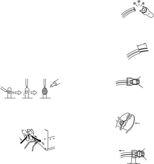
•Barrier
(6)When replacing AC primary side components (transformers, power cords, noise blocking capacitors, etc.) wrap ends of wires securely about the terminals before soldering.
Fig.1-1-1
(7)Observe that wires do not contact heat producing parts (heatsinks, oxide metal film resistors, fusible resistors, etc.)
(8)Check that replaced wires do not contact sharp edged or pointed parts.
(9)When a power cord has been replaced, check that 10-15 kg of force in any direction will not loosen it.
Power cord
Fig.1-1-2
(10)Also check areas surrounding repaired locations.
(11)Products using cathode ray tubes (CRTs)In regard to such products, the cathode ray tubes themselves, the high voltage circuits, and related circuits are specified for compliance with recognized codes pertaining to X-ray emission.
Consequently, when servicing these products, replace the cathode ray tubes and other parts with only the specified parts. Under no circumstances attempt to modify these circuits.Unauthorized modification can increase the high voltage value and cause X-ray emission from the cathode ray tube.
(12)Crimp type wire connectorIn such cases as when replacing the power transformer in sets where the connections between the power cord and power trans former primary lead wires are performed using crimp type connectors, if replacing the connectors is unavoidable, in order to prevent safety hazards, perform carefully and precisely according to the following steps.
•Connector part number :E03830-001
•Required tool : Connector crimping tool of the proper type which will not damage insulated parts.
•Replacement procedure
a)Remove the old connector by cutting the wires at a point close to the connector.Important : Do not reuse a connector (discard it).
cut close to connector
Fig.1-1-3
b)Strip about 15 mm of the insulation from the ends of the wires. If the wires are stranded, twist the strands to avoid frayed conductors.
15 mm
Fig.1-1-4
c)Align the lengths of the wires to be connected. Insert the wires fully into the connector.
Metal sleeve
Connector
Fig.1-1-5
d)As shown in Fig.1-1-6, use the crimping tool to crimp the metal sleeve at the center position. Be sure to crimp fully to the complete closure of the tool.
25 |
Crimping tool |
1. |
|
2. |
|
0 |
|
5.5
Fig.1-1-6
e) Check the four points noted in Fig.1-1-7.
Not easily pulled free |
Crimped at approx. center |
|
of metal sleeve |
||
|
||
|
Conductors extended |
Wire insulation recessed more than 4 mm
Fig.1-1-7
(No.YD048)1-3
1.1.2 Safety Check after Servicing
Examine the area surrounding the repaired location for damage or deterioration. Observe that screws, parts and wires have been returned to original positions, Afterwards, perform the following tests and confirm the specified values in order to verify compliance with safety standards.
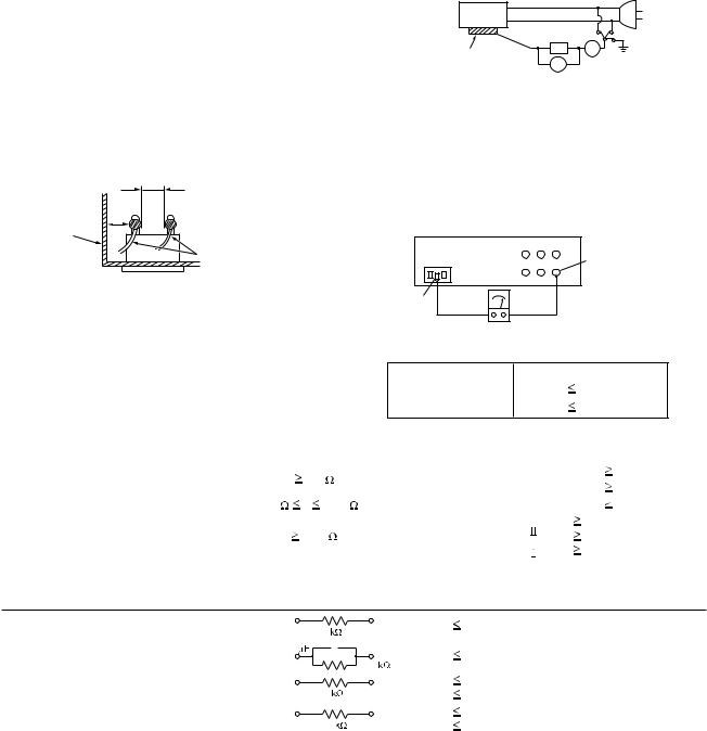
(1)Insulation resistance test
Confirm the specified insulation resistance or greater between power cord plug prongs and externally exposed parts of the set (RF terminals, antenna terminals, video and audio input and output terminals, microphone jacks, earphone jacks, etc.).See table 1 below.
(2)Dielectric strength test
Confirm specified dielectric strength or greater between power cord plug prongs and exposed accessible parts of the set (RF terminals, antenna terminals, video and audio input and output terminals, microphone jacks, earphone jacks, etc.). See Fig.1-1-11 below.
(3)Clearance distance
When replacing primary circuit components, confirm specified clearance distance (d), (d') between soldered terminals, and between terminals and surrounding metallic parts. See Fig.1-1-11 below.
d
d'
Chassis
Power cord primary wire
Fig.1-1-8
(4)Leakage current test
Confirm specified or lower leakage current between earth ground/power cord plug prongs and externally exposed accessible parts (RF terminals, antenna terminals, video and audio input and output terminals, microphone jacks, earphone jacks, etc.).
Measuring Method : (Power ON)Insert load Z between earth ground/power cord plug prongs and externally exposed accessible parts. Use an AC voltmeter to measure across both terminals of load Z. See Fig.1-1-9 and following Fig.1-1-12.
|
|
a |
b |
Externally |
Z |
A |
c |
|
|||
|
|
|
|
exposed |
V |
|
|
accessible part |
|
|
|
Fig.1-1-9
(5)Grounding (Class 1 model only)
Confirm specified or lower grounding impedance between earth pin in AC inlet and externally exposed accessible parts (Video in, Video out, Audio in, Audio out or Fixing screw etc.).Measuring Method:
Connect milli ohm meter between earth pin in AC inlet and exposed accessible parts. See Fig.1-1-10 and grounding specifications.
AC inlet |
Exposed accessible part |
Earth pin |
MIlli ohm meter |
|
|
|
Grounding Specifications |
|
|
|
Region |
Grounding Impedance (Z) |
||
|
|
|
|
USA & Canada |
Z |
|
0.1 ohm |
|
|
|
|
Europe & Australia |
Z |
|
0.5 ohm |
Fig.1-1-10
AC Line Voltage |
Region |
|
|
|
|
|
( ) |
Dielectric Strength |
|
Clearance Distance (d), (d') |
|||||||||||
Insulation Resistance R |
|
||||||||||||||||||||
100 V |
Japan |
R |
|
|
1 M /500 V DC |
AC 1 kV 1 minute |
|
|
d, d' |
3 mm |
|||||||||||
|
|
|
|
|
|
|
|
|
|
|
|
|
|||||||||
100 to 240 V |
|
|
AC 1.5 kV 1 minute |
|
|
d, d' |
4 mm |
||||||||||||||
|
|
|
|
|
|
|
|
|
|
|
|
|
|||||||||
|
|
|
|
|
|
|
|
|
|
|
|
|
|
|
|
|
|
|
|||
110 to 130 V |
USA & Canada |
1 M |
|
|
|
R |
|
12 M /500 V DC |
AC 1 kV 1 minute |
|
|
d, d' |
|
|
3.2 mm |
||||||
|
|
|
|
|
|
|
|
|
|
|
|
|
|
|
|
|
|
|
|||
110 to 130 V |
|
|
|
|
|
|
|
|
|
|
|
AC 3 kV 1 minute |
|
d |
|
4 mm |
|
||||
Europe & Australia |
R |
10 M /500 V DC |
|
|
(Class |
) |
d' |
|
8 mm |
(Power cord) |
|||||||||||
|
|
|
|
||||||||||||||||||
200 to 240 V |
AC 1.5 kV 1 minute |
|
|
||||||||||||||||||
|
|
|
|
|
|
|
|
|
|
|
|
d' |
|
6 mm (Primary wire) |
|||||||
|
|
|
|
|
|
|
|
|
|
|
|
|
|
(Class |
) |
|
|||||
|
|
|
|
|
|
|
|
|
|
|
|
|
|
||||||||
|
|
|
|
|
|
|
|
|
Fig.1-1-11 |
|
|
|
|
|
|
|
|
|
|
||
|
|
|
|
|
|
|
|
|
|
|
|
|
|
|
|
|
|
||||
AC Line Voltage |
Region |
|
|
|
|
|
|
Load Z |
Leakage Current (i) |
|
|
|
|
a, b, c |
|||||||
100 V |
Japan |
|
|
|
|
|
1 |
|
|
i |
|
1 mA rms |
|
Exposed accessible parts |
|||||||
|
|
|
|
|
|
|
|
|
|
|
|
|
|
|
|
|
|
|
|||
|
|
|
|
|
|
|
|
|
|
|
|
|
|
|
|
|
|
|
|||
110 to 130 V |
USA & Canada |
0.15 |
|
|
|
|
|
|
i |
|
0.5 mA rms |
|
Exposed accessible parts |
||||||||
|
|
|
|
|
1.5 |
|
|
||||||||||||||
|
|
|
|
|
|
|
|||||||||||||||
|
|
|
|
|
|
|
|
|
|
|
|
|
|
|
|
|
|||||
110 to 130 V |
|
|
|
|
|
|
2 |
|
|
i |
|
0.7 mA peak |
|
Antenna earth terminals |
|||||||
Europe & Australia |
|
|
|
|
|
|
|
i |
|
2 mA dc |
|
||||||||||
|
|
|
|
|
|
|
|
|
|
|
|
|
|
|
|||||||
220 to 240 V |
|
|
|
|
|
|
|
|
|
|
|
|
|
|
|
|
|
|
|
|
|
|
|
|
|
|
|
|
|
|
|
i |
|
0.7 mA peak |
|
Other terminals |
|||||||
|
|
|
|
|
|
|
|
|
|
|
|
|
|||||||||
|
|
|
|
|
|
|
50 |
|
i |
|
2 mA dc |
|
|||||||||
|
|
|
|
|
|
|
|
|
|
|
|
|
|
|
|
||||||
|
|
|
|
|
|
|
|
|
|
|
|
|
|
|
|
|
|
|
|
|
|
Fig.1-1-12
NOTE :
These tables are unofficial and for reference only. Be sure to confirm the precise values for your particular country and locality.
1-4 (No.YD048)
1.2Hard Disk Drive (HDD) Handling Precautions
The HDD is a precision device for use in reading and writing a large amount of data on or from a disk rotating at a high speed. If it is not handled carefully, either abnormal operation may result or it may not be possible to read data. The HDD is sensitive to the following items and special care is required in safeguarding against them when handling an HDD. Also take care in handling a set incorporating an HDD.
(1)Vibrations and impacts
(2)Static electricity
(3)Rough handling
1.2.1 Handling in transport, etc.
•Be sure to place the HDD in the manufacturer's specified package carton before transport.
•When receiving a package containing an HDD, check that the package carton is not damaged (such as having holes in the carton, crushed corners, etc.).
•Do not impact the packaging carton when loading or unloading it.
•It is not permitted to use the inner package carton only for transporting an HDD.
•Do not stack package cartons one upon another.
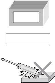
1.2.2 Handling an HDD in the stand-alone status
•When handling an HDD on a hard workbench, place an antistatic mat (rubber sheet) or similar object on the hard surface (to prevent any impacts occurring between the HDD and bench).
•Do not stack the HDDs one upon another.
•Do not knock an HDD with a hard object (such as a screwdriver).
•Do not place an HDD on its side panel without using a support (do not place an HDD in an unstable position).
1.2.3 Handling the installation of an HDD
HDD
Do not throw or drop packages.
Be sure to package and transport the HDDs correctly.
•Place antistatic mats or similar sheets on all of the surfaces on which work is conducted or when the HDD is transported.
•Do not permit the HDD to knock against the set's brackets.
•When screwing the brackets, be careful not to knock the HDD. When using a power screwdriver, use a low-shock model and arrange the tightening torque properly.
•When mounting an HDD in a main body, take care not to apply excessive force to the brackets.
(No.YD048)1-5

SECTION 2
SPECIFIC SERVICE INSTRUCTIONS
2.1Different table of features
The following table indicates main different points between models DR-MX1SEK, DR-MX1SEU/EY/EZ and DR-MX1SEF.
ITEM |
DR-MX1SEK |
DR-MX1SEU / EY / EZ |
DR-MX1SEF |
|
|
|
|
POWER PLUG |
3PIN |
CEE |
← |
|
|
|
|
VHS |
PAL/NTSC PB on PAL TV with |
PAL/MESECAM (MANUAL) / |
← |
|
HiFi |
NTSC PB on PAL TV with HiFi |
|
|
|
||
BROADCASTING STANDARD |
I |
B/G, D/K |
L, L', B/G |
|
|
|
|
STEREO DECODER |
NICAM |
NICAM/A2 |
NICAM(L, B/G) / A2(B/G) |
|
|
|
|
VCR PLUS+ |
VIDEO Plus+DELUXE |
SHOWVIEW DELUXE |
← |
|
|
|
|
VPS/PDC |
NOT USED |
USED |
NOT USED |
|
|
|
|
Note:
Mark ← as same as left.
2.2Service position
This unit has been designed so that the Mechanism and Main board assemblies can be removed together from the bottom chassis. Before diagnosing or servicing the circuit boards, take out the major parts from the bottom chassis.
2.2.1 How to set the "Service position"
(1)Refer to the disassembly procedure and perform the disassembly of the major parts before removing the Mechanism assembly.
(2)Remove the screws that fix the Mechanism, Main board assembly to the bottom chassis. If any other screws are used to fix the boards, remove them also.
(3)Remove the combined Mechanism, HDD, DVD unit, switching regulator, digital, junction and Main board assemblies.
(4)If any other major parts are used, remove them also.
(5)Connect the wires and connectors of the major parts that have been removed in steps (1) to (4). (Refer to Fig. 2-2a.)
(6)Place the combined Mechanism, Main board and other board assemblies upside down.
(7)Insert the power cord plug into the power outlet and then proceed with the diagnostics and servicing of the board assembly.
Notes:
•Before inserting the power cord plug into the power outlet, make sure that none of the electrical parts are able to short-circuit between the workbench and the board assembly.
•For the disassembly procedure of the major parts and details of the precautions to be taken, see "Removing the major parts".
•If there are wire connections from the Main board and Mechanism assemblies to the other major parts, be sure to remove them (including wires connected to the major parts) first before performing step (2).
•When carrying out diagnosis and repair of the Main board assembly in the "Service position", be sure to ground both the Main board and Mechanism assemblies. If they are improperly grounded, there may be noise on the playback picture or FDP counter display may move even when the mechanism is kept in an inoperative status.
•In order to diagnose the playback or recording of the cassette tape, set the Mechanism assembly to the required mode before placing it upside down. If the mechanism mode is changed (including ejection) while it is in an upside down position the tape inside may be damaged.
•For some models, the mechanism and board assemblies are attached by connectors only. When carrying out a diagnosis or repair of the boards in the "Service position", make sure that the connectors are not disconnected.
HDD |
|
Switchcing regulator |
|
board assy |
Main board assy |
|
TP111 D.FF |
Junction board |
TP106 PB FM |
|
|
assy |
TP2253 A.PB FM |
|
TP4001 CTL.P |
Digital board |
|
assy |
|
Jack board |
|
assy |
|
DVD WPKV |
|
Switch display board assy |
Operation jack board assy |
|
Fig.2-2a |
1-6 (No.YD048)

2.3Jig RCU mode
This unit uses the following two modes for receiving remote control codes.
(1)User RCU mode:Ordinary mode for use by the user.
(2)Jig RCU mode: Mode for use in production and servicing. When using the Jig RCU, it is required to set the unit to the Jig RCU mode (the mode in which codes from the Jig RCU can be received). As both of the above two modes are stored in the EEPROM, it is required to set the unit back to the User RCU mode each time that an adjustment is made or to check that the necessary operations have been completed.These modes can be set by the operations described below.
Note:
•When the unit is set to Jig RCU mode and when the unit is under Jig RCU mode, the remote control unit attached to product operates only in "Remote Control Code 1". Since the unit is in "Remote Control Code 3" when it is shipped and just after its batteries are changed, "Remote Control Code 3" needs to be changed to "Remote Control Code 1."
•Confirm the RCU mode when exchanged parts. Since some SERVICE PARTS sets the unit to the Jig RCU mode as initial setting. Therefore please set the unit to the user RCU mode after replacing the EEPROM.
User RCU mode
Jig RCU mode
 (
(  blinked)
Fig.2-3a User/Jig RCU mode
2.3.1 Changing Remote Control Code
(1)Slide the TV/CABLE/SAT/DVD switch to DVD.
(2)Press the numeric button "1" of the remote control unit while pressing the "SET UP" button of the remote control unit. Then,press the "ENTER" button, and then release the "SET UP" button.
(3)Press the "POWER" button on the unit to turn off the unit.
(4)Press the "PLAY" button on the unit for over 5 seconds while the unit is turned off. The code currently set appears on the front display panel.
(5)Press the "STOP" button on the remote control to change the unit’s code. When FDP indicator displays "DVD1," it means that the Remote Control Code has been changed to "1."
2.3.2Setting the Jig RCU mode
(1) Turn on the power.
(2) Press the "VHS/HDD/DVD SELECT" button repeatedly on the unit so that the VHS lamp lights up on the unit.
(3) Press the following remocon keys continuously within 2 seconds " SET UP " → " 2 " → " 8 " → " ENTER ".
When the unit is set to the Jig RCU mode, the symbols ( " : " ) in the time display of the FDP are blinked. (Refer to Fig.2-3a User/Jig RCU mode)
2.3.3Setting the User RCU mode
(1) Turn off the power.
(2)Press the "REC" and "PAUSE" buttons of the VCR simultaneously. Alternatively, transmit the code "43-9D" from the Jig RCU.
2.4Mechanism service mode
This model has a unique function to enter the mechanism into every operation mode without loading of any cassette tape. This function is called the "Mechanism service mode".
2.4.1 How to set the "Mechanism service mode"
(1)Set the unit to the Jig RCU mode (the mode in which codes from the Jig RCU can be received)
(2)Transmit the code "43-E5" from the Jig RCU.
(3)Release the lug of the Cassette holder and then slide the Cassette holder toward the direction where the Cassette holder is loaded by manually.
(4)The cassette holder lowers and, when the loading has completed, the mechanism enters the desired mode. When the unit is set to the Mechanism service mode, the symbols ("TIMER") in the FDP (LED) are blinked.
2.4.2 How to exit from the "Mechanism service mode"
(1)Unplug the power cord plug from the power outlet.
2.5Maintenance and inspection
2.5.1 Cleaning
Regular cleaning of the transport system parts is desirable but practically impossible. So make it a rule to carry out cleaning of the tape transport system whenever the machine is serviced.
When the video head, tape guide and/or brush get soiled, the playback picture may appear inferior or at worst disappear, resulting in possible tape damage.
Note:
• Absolutely avoid sweeping the upper drum vertically as this will cause damage to the video head.
(1)When cleaning the upper drum (especially the video head), soak a piece of closely woven cloth with alcohol and while holding the cloth onto the upper drum by the fingers, turn the upper drum counterclockwise.
(2)To clean the parts of the tape transport system other than the upper drum, use a piece of closely woven cloth or a cotton swab soaked with alcohol.
(3)After cleaning, make sure that the cleaned parts are completely dry before using the cassette tape.
A/C head |
Video heads |
|
Fig.2-5a
2.5.2 Lubrication
With no need for periodical lubrication, you have only to lubricate new parts after replacement. If any oil or grease on contact parts is soiled, wipe it off and newly lubricate the parts.
Note:
•See the "mechanism assembly" diagram of the "parts list" for the lubricating or greasing spots, and for the types of oil or grease to be used.
(No.YD048)1-7
2.5.3 Suggested servicing schedule for main components
The following table indicates the suggested period for such service measures as cleaning, lubrication and replacement. In practice, the indicated periods will vary widely according to environmental and usage conditions. However, the indicated components should be inspected when a set is brought for service and the maintenance work performed if necessary. Also note that rubber parts may deform in time, even if the set is not used.
System |
|
Parts name |
|
Operation hours |
|
|
|
|
|
||
|
|
1000H |
2000H |
||
|
|
|
|
||
|
|
|
|
|
|
|
|
Drum assembly |
|
C,X |
X |
|
|
|
|
|
|
|
|
A/C head |
|
C,X |
C,X |
|
|
|
|
|
|
Tape |
|
Pinch roller arm assembly |
|
C |
C |
|
|
|
|
|
|
|
Full erase head |
|
C |
C |
|
transport |
|
|
|||
|
|
|
|
|
|
|
Tension arm assembly |
|
C |
C |
|
|
|
|
|||
|
|
|
|
|
|
|
|
Capstan motor (Shaft) |
|
C |
C |
|
|
|
|
|
|
|
|
Guide arm assembly |
|
C |
C |
|
|
|
|
|
|
|
|
Capstan motor |
|
|
X |
|
|
|
|
|
|
|
|
Capstan brake assembly |
|
|
X |
|
|
|
|
|
|
|
|
Main brake assembly |
|
|
X |
|
|
|
|
|
|
Drive |
|
Belt (Capstan) |
|
X |
X |
|
|
|
|
|
|
|
Loading motor |
|
|
X |
|
|
|
|
|
||
|
|
|
|
|
|
|
|
Clutch unit |
|
|
X |
|
|
|
|
|
|
|
|
Worm gear |
|
|
X |
|
|
|
|
|
|
|
|
Control plate |
|
|
X |
|
|
|
|
|
|
Other |
|
Rotary encoder |
|
|
X |
|
|
|
|
|
|
C : Cleaning |
|
|
|
|
|
X : Inspection or Replacement if necessary |
|
|
|||
1-8 (No.YD048)

SECTION 3
DISASSEMBLY
3.1Removing the major parts
3.1.1 Destination of connectors
Two kinds of double-arrows in connection tables respectively show kinds of connector/wires.
|
|
|
: Flat wire |
: Wire |
: Board to board (B-B) |
||||
|
|
|
: The connector of the side to remove |
|
|||||
|
|
|
|
||||||
|
|
|
|
|
|
|
|
||
|
CONN. No. |
|
|
CONNECTOR |
|
PIN No. |
|||
|
|
|
|
|
|
|
|
|
|
|
|
|
|
|
|
|
|
|
|
|
|
WR2a |
Main |
CN101 |
|
Digital |
CN761 |
40 |
|
|
|
WR2b |
Main |
CN103 |
|
Digital |
CN762 |
10 |
|
|
|
|
|
|
|
|
|||
Destination of connectors |
|
|
|
||||||
|
|
|
|
|
|
|
|
||
|
CONN. No. |
|
|
CONNECTOR |
|
PIN No. |
|||
|
|
|
|
|
|
|
|
|
|
|
WR2a |
Main |
CN7112 |
|
Operation/jack CN7201 |
9 |
|||
|
WR2b |
Main |
CN3102 |
|
Switch/display |
CN7001 |
11 |
||
|
WR2c |
Junction |
CN7103 |
|
Switch/display |
CN7002 |
4 |
||
|
WR3a |
Main |
CN2001 |
|
A/C head |
|
6 |
||
|
WR3b |
Drum |
|
|
Main |
CN1 |
9 |
||
|
assembly |
|
|
||||||
|
|
|
|
|
|
|
|
|
|
|
|
|
|
|
|
|
|
||
|
WR4a |
DVD unit |
|
|
Digital |
CN2201 |
40 |
||
|
WR4b |
DVD unit |
|
|
Junction |
CN5304 |
4 |
||
|
WR5a |
HDD |
|
|
Digital |
CN2101 |
40 |
||
|
WR5b |
Junction |
CN7106 |
|
Digital |
CN1405 |
4 |
||
|
WR5c |
Junction |
CN5502 |
|
Digital |
CN1003 |
6 |
||
|
CN7108 |
Junction |
CN7108 |
|
Digital |
CN1001 |
28 |
||
|
(CN1001) |
|
|||||||
|
|
|
|
|
|
|
|
||
|
CN7109 |
Junction |
CN7109 |
|
Digital |
CN1002 |
20 |
||
|
(CN1002) |
|
|||||||
|
|
|
|
|
|
|
|
||
|
CN7121 |
Junction |
CN7121 |
|
Digital |
CN1801 |
10 |
||
|
(CN1801) |
|
|||||||
|
|
|
|
|
|
|
|
||
|
WR6a |
Junction |
CN7126 |
|
Jack |
CN4104 |
6 |
||
|
WR7a |
Junction |
CN7123 |
|
Video switch |
CN501 |
4 |
||
|
WR7b |
Main |
CN3103 |
|
Junction |
CN7102 |
15 |
||
|
WR7c |
Main |
CN2601 |
|
Junction |
CN8001 |
11 |
||
|
WR7d |
Junction |
CN7107 |
|
Main |
CN7111 |
9 |
||
|
WR7e |
SW. REG. CN5304 |
|
Junction |
CN5501 |
19 |
|||
|
WR8a |
SW. REG. CN5301 |
|
Main |
CN5311 |
15 |
|||
|
WR8b |
SW. REG. CN5302 |
|
Fun motor |
|
2 |
|||
|
WR8c |
SW. REG. CN5303 |
|
HDD |
|
4 |
|||
|
WR12a |
Tuner |
CN6001 |
|
Main |
CN7116 |
14 |
||
|
WR12b |
Tuner |
CN6003 |
|
Main |
CN7118 |
7 |
||
|
WR12c |
Tuner |
CN6002 |
|
Main |
CN7117 |
13 |
||
|
WR13a |
Main |
CN7119 |
|
SECAM |
CN301 |
15 |
||
|
WR13b |
Video switch CN504 |
|
SECAM |
CN4302 |
6 |
|||
|
|
|
|
|
|
|
|
|
|
3.1.2 How to read the procedure table
This table shows the steps for disassembly of the externally furnished parts and board assemblies. Reverse these steps when re-assembling them.
Step/ |
Part Name |
Fig. |
Point |
Note |
||||||
LocNo. |
No. |
|||||||||
|
|
|
|
|
|
|||||
|
|
|
|
|
||||||
[1] |
Top cover |
3-1a |
4(S1a),(S1b),3(L1a), |
<Note 1a> |
||||||
|
|
|
|
|
|
2(SD1a),(P1a),(W1a), |
|
|
||
|
|
|
|
|
|
CN1(WR1a), |
|
|
||
|
|
Bracket |
|
|
---------------------------------------- |
|||||
|
|
|
|
2(S1c) |
|
|
||||
|
|
|
|
|
|
|
|
|
|
|
|
|
|
|
|
|
|
|
|
|
|
(1) |
(2) |
(3) |
(4) |
(5) |
||||||
(1)Order of steps in Procedure
When reassembling, perform the step(s) in the reverse order.
These numbers are also used as the identification (location) No. of parts Figures.
(2)Part name to be removed or installed.
(3)Fig. No. showing procedure or part location.
(4)Identification of part to be removed, unhooked, unlocked, released, unplugged, unclamped or unsoldered.
P= Spring, W= Washer, S= Screw, L= Locking tab, SD= Solder, CN**(WR**)= Remove the wire (WR**) from the connector (CN**).
Note:
•The bracketed ( ) WR of the connector symbol are assigned nos. in priority order and do not correspond to those on the spare parts list.
(5)Adjustment information for installation
3.1.3 Disassembly procedure
Step/ |
Part Name |
Fig. |
Point |
Note |
|
LocNo. |
No. |
||||
|
|
|
|||
|
|
|
|
|
|
[1] |
Top cover |
3-1d |
8(S1a) |
|
|
[2] |
Front panel assembly |
3-1a, |
3(L2a),5(L2b) |
<Note2a> |
|
|
(Operation/jack board assembly) |
3-1d |
CN7112(WR2a) |
<Note2b> |
|
|
(Switch/display board assembly) |
3-1e |
CN3102(WR2b) |
|
|
|
|
|
CN7103(WR2c) |
|
|
[3] |
Mechanism assembly |
3-1b, |
CN2001(WR3a) |
<Note2a> |
|
|
|
3-1c, |
3(S3a),(S3b) |
<Note3a> |
|
|
(Drum assembly) |
3-1d |
CN(WR3b) |
<Note3b> |
|
|
|
3-1e |
(S3c),(S3d),(S3e) |
|
|
[4] |
DVD unit |
3-1d |
4(S4a),4(S4b) |
<Note2a> |
|
|
(Bracket) |
3-1e |
(WR4a),(WR4b) |
|
|
[5] |
Digital board assembly |
3-1d |
4(S5a),CN2101(WR5a) |
<Note2a> |
|
|
|
3-1e |
CN7106(WR5b),CN5502(WR5c) |
|
|
|
|
|
CN7108(CN1001),CN7109(CN1002), |
|
|
|
|
|
CN7121(CN1801) |
|
|
[6] |
Jack board assembly |
3-1d |
2(S6a),CN7126(WR6a) |
|
|
[7] |
Junction board assembly |
3-1d |
(S7a),CN7123(WR7a), |
<Note2a> |
|
|
|
3-1e |
CN3103(WR7b),CN2601 |
|
|
|
|
|
(WR7c),CN7107(WR7d), |
|
|
|
|
|
CN5304(WR7e) |
|
|
[8] |
Switching Regulator |
3-1d |
4(S8a) |
<Note2a> |
|
|
board assembly |
3-1e |
CN5301(WR8a), |
|
|
|
|
|
CN5302(WR8b), |
|
|
|
|
|
CN5303(WR8c) |
|
|
[9] |
Rear cover |
3-1d |
(S9a),8(S9b),(S9c),3(L9a) |
|
|
[10] |
HDD |
3-1d |
4(S10a),4(S10b) |
|
|
|
(Bracket, sheet) |
3-1e |
|
|
|
[11] |
Main board assembly |
3-1d |
2(S11a) |
|
|
[12] |
Tuner board assembly |
3-1d |
CN6001(WR12a),CN6003 |
|
|
|
|
3-1e |
(WR12b),CN6002(WR12c) |
|
|
[13] |
SECAM board assembly |
3-1d |
2(S13a), CN7119(WR13a) |
|
|
|
(EF model) |
3-1e |
CN504(WR13b) |
|
<Note 2a>
•Be careful not to damage the connector and wire etc. during connection and disconnection.
•When connecting the flat wire to the connector, be careful with the flat wire direction.
(No.YD048)1-9
Loading...