


DLA-HD350WE
Table of contents
 Loading...
Getting Started
Preparation
Basic Operation
Troubleshooting
Settings
Others
1108TTH-AO-AO
© 2008 Victor Company of Japan, Limited
DLA-HD350
D-ILA PROJECTOR
PROYECTOR D-ILA
PROJECTEUR D-ILA
DLA-HD350
For Customer use :
Enter below the serial No. which is
located on the side of the cabinet.
Retain this information for future
reference.
Model No. DLA-HD350
Serial No.
Instrucción para el cliente :
Introduzca a continuación el nº de
serie que aparece en la parte
inferior lateral de la caja. Conserve
esta información como referencia
para uso ulterior.
Modelo Nº DLA-HD350
Nº de serie
Pour utilisation par le client :
Entrer ci-dessous le N° de série qui
est situé sous le boîtier. Garder
cette information comme référence
pour le futur.
N° de modèle DLA-HD350
N° de série
DLA-HD350
D-ILA PROJECTOR
INSTRUCTIONS
ENGLISH FRANÇAIS ESPAÑOL/CASTELLANO
PROJECTEUR D-ILA
MANUEL D’INSTRUCTIONS
PROYECTOR D-ILA
MANUAL DE INSTRUCCIONES
PB006586699-1
1
Getting started
2
Safety Precautions
IMPORTANT INFORMATION
About the installation place
Do not install the projector in a place that cannot support
its weight securely.
If the installation place is not sturdy enough, the projector
could fall or overturn, possibly causing personal injury.
IMPORTANT SAFEGUARDS
Electrical energy can perform many useful functions. This
unit has been engineered and manufactured to assure your
personal safety. But IMPROPER USE CAN RESULT IN
POTENTIAL ELECTRICAL SHOCK OR FIRE HAZARD. In
order not to defeat the safeguards incorporated into this
product, observe the following basic rules for its installation,
use and service. Please read these Important Safeguards
carefully before use.
- All the safety and operating instructions should be read
before the product is operated.
- The safety and operating instructions should be retained
for future reference.
- All warnings on the product and in the operating instructions
should be adhered to.
- All operating instructions should be followed.
- Place the projector near a wall outlet where the plug can
be easily unplugged.
- Unplug this product from the wall outlet before cleaning.
Do not use liquid cleaners or aerosol cleaners. Use a damp
cloth for cleaning.
- Do not use attachments not recommended by the product
manufacturer as they may be hazardous.
- Do not use this product near water. Do not use immediately
after moving from a low temperature to high temperature,
as this causes condensation, which may result in fire,
electric shock, or other hazards.
- Do not place this product on an unstable cart, stand, or
table. The product may fall, causing serious injury to a
child or adult, and serious damage to the product. The
product should be mounted according to the manufacturer’s
instructions, and should use a mount recommended by
the manufacturer.
- When the product is used on a cart, care
should be taken to avoid quick stops,
excessive force, and uneven surfaces
which may cause the product and cart to
overturn, damaging equipment or causing
possible injury to the operator.
- Slots and openings in the cabinet are
provided for ventilation. These ensure reliable operation of
the product and protect it from overheating. These openings
must not be blocked or covered. (The openings should
never be blocked by placing the product on bed, sofa, rug,
or similar surface. It should not be placed in a built-in installation
such as a bookcase or rack unless proper ventilation is
provided and the manufacturer’s instructions have been
adhered to.)
Th is p ro du ct h as a H ig h In te ns it y
Discharge (HID) lamp that contains
mercury.
Disposal of these materials may be
regulated in your community due to
environmental considerations . For
disposal or recycling information, please
contact your local authorities or for USA,
the Electronic Industries Alliance:
http://www.eiae.org.
WARNING:
TO PREVENT FIRE OR SHOCK HAZARDS, DO NOT
EXPOSE THIS APPLIANCE TO RAIN OR MOISTURE.
WARNING:
THIS APPARATUS MUST BE EARTHED.
CAUTION:
To reduce the risk of electric shock, do not remove cover.
Refer servicing to qualified service personnel.
This projector is equipped with a 3-blade grounding
type plug to satisfy FCC rule. If you are unable to insert
the plug into the outlet, contact your electrician.
FCC INFORMATION (U.S.A. only)
CAUTION:
Changes or modification not approved by JVC could
void the user’s authority to operate the equipment.
NOTE:
This equipment has been tested and found to comply
with the limits for Class B digital devices, pursuant to
Part 15 of the FCC Rules. These limits are designed to
provi d e r ea s on ab le pr ot ec t io n ag a in st h a rm fu l
interference in a residential installation. This equipment
generates, uses, and can radiate radio frequency energy
and, if not installed and used in accordance with the
instructions, may cause harmful interference to radio
communications. However, there is no guarantee that
interference will not occur in a particular installation.
If this equipment does cause harmful interference to
radio or television reception, which can be determined
by turning the equipment off and on, the user is encourage
to try to correct the interference by one or more of the
following measures:
●Reorient or relocate the receiving antenna.
●Increase the separation between the equipment and
receiver.
●Connect the equipment into an outlet on a circuit different
from that to which the receiver is connected.
●Consult the dealer or an experienced radio/TV technician
for help.
MACHINE NOISE INFORMATION (Germany only)
Changes Machine Noise Information Ordinance 3. GSGV,
January 18, 1991: The sound pressure level at the operator
position is equal or less than 19 dB (A) according to
ISO 7779.
PORTABLE CART WARNING
(symbol provided by RETAC)
S3126A
-
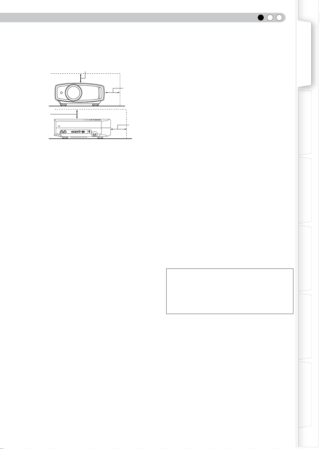
To allow better heat dissipation, keep a clearance between
this unit and its surrounding as shown below. When this
unit is enclosed in a space of dimensions as shown below,
use an air-conditioner so that the internal and external
temperatures are the same.
-
the type of power supply to your home, consult your
product dealer or local power company.
- This product is equipped with a three-wire plug. This plug
will fit only into a grounded power outlet. If you are unable
to insert the plug into the outlet, contact your electrician to
install the proper outlet. Do not defeat the safety purpose
of the grounded plug.
- Power-supply cords should be routed so that they are not
likely to be walked on or pinched by items placed upon or
against them. Pay particular attention to cords at doors,
plugs, receptacles, and the point where they exit from the
product.
- For added protection of this product during a lightning
storm, or when it is left unattended and unused for long
periods of time, unplug it from the wall outlet and
disconnect the cable system. This will prevent damage to
the product due to lightning and power line surges.
- Do not overload wall outlets, extension cords, or
convenience receptacles on other equipment as this can
result in a risk of fire or electric shock.
- Never push objects of any kind into this product through
openings as they may touch dangerous voltage points or
short out parts that could result in a fire or electric shock.
Never spill liquid of any kind on the product.
- Do not attempt to service this product yourself as opening
or removing covers may expose you to dangerous
voltages and other hazards. Refer all service to qualified
service personnel.
-
Unplug this product from the wall outlet and refer service to
qualified service personnel under the following conditions:
a) When the power supply cord or plug is damaged.
b) If liquid has been spilled, or objects have fallen on the product.
c) If the product has been exposed to rain or water.
d) If the product does not operate normally by following the
operating instructions. Adjust only those controls that are
covered by the Operation Manual, as an improper adjustment
of controls may result in damage and will often require
extensive work by a qualified technician to restore the product
to normal operation.
e) If the product has been dropped or damaged in any way.
f) When the product exhibits a distinct change in performance -
this indicates a need for service.
- When replacement parts are required, be sure the service
technician has used replacement parts specified by the
manufacturer or with same characteristics as the original
part. Unauthorized substitutions may result in fire, electric
shock, or other hazards.
-
Upon completion of any service or repairs to this product,
ask the service technician to perform safety checks to
determine that the product is in proper operating condition.
- The product should be placed more than one foot away
from heat sources such as radiators, heat registers,
stoves, and other products (including amplifiers) that
produce heat.
- When connecting other products such as VCR’s, and DVD
players, you should turn off the power of this product for
protection against electric shock.
- Do not place combustibles behind the cooling fan. For
example, cloth, paper, matches, aerosol cans or gas
lighters that present special hazards when over heated.
- Do not look into the projection lens while the illumination
lamp is turned on. Exposure of your eyes to the strong
light can result in impaired eyesight.
- Do not look into the inside of this unit through vents
(ventilation holes), etc. Do not look at the illumination lamp
directly by opening the cabinet while the illumination lamp
is turned on. The illumination lamp also contains ultraviolet
rays and the light is so powerful that your eyesight can be
impaired.
- Do not drop, hit, or damage the light-source lamp (lamp
unit) in any way. It may cause the light-source lamp to
break and lead to injuries. Do not use a damaged light
source lamp. If the light-source lamp is broken, ask your
dealer to repair it. Fragments from a broken light-source
lamp may cause injuries.
- The light-source lamp used in this projector is a high
pressure mercury lamp. Be careful when disposing of the
light-source lamp. If anything is unclear, please consult
your dealer.
- Do not ceiling-mount the projector to a place which tends
to vibrate; otherwise, the attaching fixture of the projector
could be broken by the vibration, possibly causing it to fall
or overturn, which could lead to personal injury.
- Use only the accessory cord designed for this product to
prevent shock.
*DO NOT allow any unqualified person to install the
unit.
Be sure to ask your dealer to install the unit (e.g.
attaching it to the ceiling) since special technical
knowledge and skills are required for installation. If
installation is performed by an unqualified person, it
may cause personal injury or electrical shock.
power source indicated on the label. If you are not sure of
150 mm
and above
150 mm and above
300 mm
and above
200 mm
and above
Safety Precautions
ENGLISH
3
Getting Started
Preparation
Basic Operation
Troubleshooting
Settings
Others
-
To allow better heat dissipation, keep a clearance between
this unit and its surrounding as shown below. When this
unit is enclosed in a space of dimensions as shown below,
use an air-conditioner so that the internal and external
temperatures are the same.
-
the type of power supply to your home, consult your
product dealer or local power company.
- This product is equipped with a three-wire plug. This plug
will fit only into a grounded power outlet. If you are unable
to insert the plug into the outlet, contact your electrician to
install the proper outlet. Do not defeat the safety purpose
of the grounded plug.
- Power-supply cords should be routed so that they are not
likely to be walked on or pinched by items placed upon or
against them. Pay particular attention to cords at doors,
plugs, receptacles, and the point where they exit from the
product.
- For added protection of this product during a lightning
storm, or when it is left unattended and unused for long
periods of time, unplug it from the wall outlet and
disconnect the cable system. This will prevent damage to
the product due to lightning and power line surges.
- Do not overload wall outlets, extension cords, or
convenience receptacles on other equipment as this can
result in a risk of fire or electric shock.
- Never push objects of any kind into this product through
openings as they may touch dangerous voltage points or
short out parts that could result in a fire or electric shock.
Never spill liquid of any kind on the product.
- Do not attempt to service this product yourself as opening
or removing covers may expose you to dangerous
voltages and other hazards. Refer all service to qualified
service personnel.
-
Unplug this product from the wall outlet and refer service to
qualified service personnel under the following conditions:
a) When the power supply cord or plug is damaged.
b) If liquid has been spilled, or objects have fallen on the product.
c) If the product has been exposed to rain or water.
d) If the product does not operate normally by following the
operating instructions. Adjust only those controls that are
covered by the Operation Manual, as an improper adjustment
of controls may result in damage and will often require
extensive work by a qualified technician to restore the product
to normal operation.
e) If the product has been dropped or damaged in any way.
f) When the product exhibits a distinct change in performance -
this indicates a need for service.
- When replacement parts are required, be sure the service
technician has used replacement parts specified by the
manufacturer or with same characteristics as the original
part. Unauthorized substitutions may result in fire, electric
shock, or other hazards.
-
Upon completion of any service or repairs to this product,
ask the service technician to perform safety checks to
determine that the product is in proper operating condition.
- The product should be placed more than one foot away
from heat sources such as radiators, heat registers,
stoves, and other products (including amplifiers) that
produce heat.
- When connecting other products such as VCR’s, and DVD
players, you should turn off the power of this product for
protection against electric shock.
- Do not place combustibles behind the cooling fan. For
example, cloth, paper, matches, aerosol cans or gas
lighters that present special hazards when over heated.
- Do not look into the projection lens while the illumination
lamp is turned on. Exposure of your eyes to the strong
light can result in impaired eyesight.
- Do not look into the inside of this unit through vents
(ventilation holes), etc. Do not look at the illumination lamp
directly by opening the cabinet while the illumination lamp
is turned on. The illumination lamp also contains ultraviolet
rays and the light is so powerful that your eyesight can be
impaired.
- Do not drop, hit, or damage the light-source lamp (lamp
unit) in any way. It may cause the light-source lamp to
break and lead to injuries. Do not use a damaged light
source lamp. If the light-source lamp is broken, ask your
dealer to repair it. Fragments from a broken light-source
lamp may cause injuries.
- The light-source lamp used in this projector is a high
pressure mercury lamp. Be careful when disposing of the
light-source lamp. If anything is unclear, please consult
your dealer.
- Do not ceiling-mount the projector to a place which tends
to vibrate; otherwise, the attaching fixture of the projector
could be broken by the vibration, possibly causing it to fall
or overturn, which could lead to personal injury.
- Use only the accessory cord designed for this product to
prevent shock.
*DO NOT allow any unqualified person to install the
unit.
Be sure to ask your dealer to install the unit (e.g.
attaching it to the ceiling) since special technical
knowledge and skills are required for installation. If
installation is performed by an unqualified person, it
may cause personal injury or electrical shock.
power source indicated on the label. If you are not sure of
150 mm
and above
150 mm and above
300 mm
and above
200 mm
and above
1
Getting started
4
Dear Customer,
This apparatus is in conformance with the valid European directives and standards regarding electromagnetic
compatibility and electrical safety.
European representative of Victor Company of Japan, Limited is:
JVC Technical Services Europe GmbH
Postfach 10 05 04
61145 Friedberg
Germany
Safety Precautions (Continued)
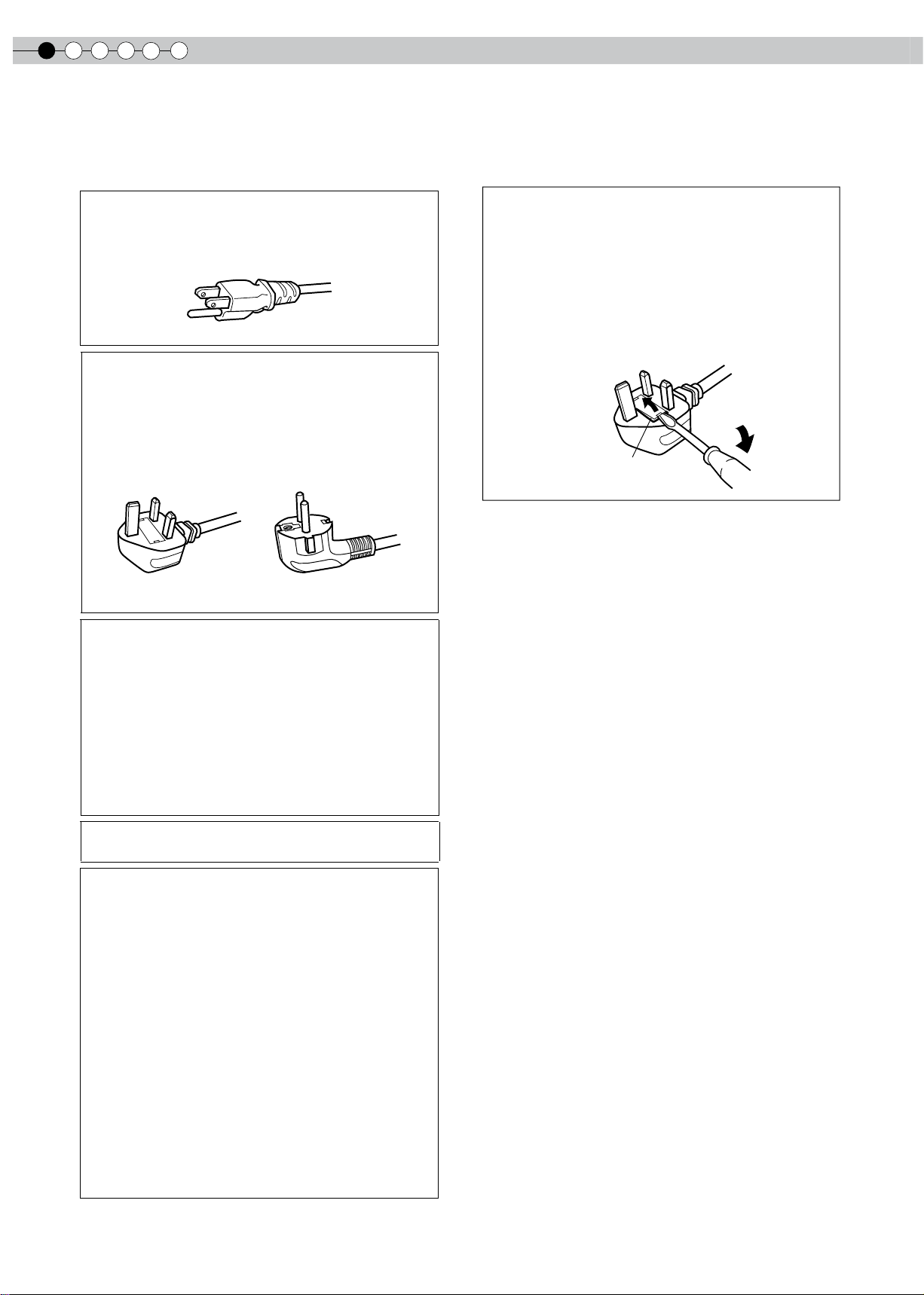
POWER CONNECTION
WARNING:
Do not cut off the main plug from this equipment.
If the plug fitted is not suitable for the power points in
your home or the cable is too short to reach a power
point, then obtain an appropriate safety approved
extension lead or adapter or consult your dealer.
If nonetheless the mains plug is cut off, dispose of the
plug immediately, to avoid a possible shock hazard by
inadvertent connection to the main supply. If a new main
plug has to be fitted, then follow the instruction given
below.
WARNING:
THIS APPARATUS MUST BE EARTHED.
For USA and Canada only
Use only the following power cord.
Power cord
The power supply voltage rating of this product is
AC110V – AC240V. Use only the power cord designated
by our dealer to ensure Safety and EMC.
Ensure that the power cable used for the projector is the
correct type for the AC outlet in your country. Consult
your product dealer.
Power cord
For United Kingdom For European continent
countries
IMPORTANT (Europe only):
The wires in the mains lead on this product are colored
in accordance with the following cord:
Green-and-yellow : Earth
Blue : Neutral
Brown : Live
As these colors may not correspond with the colored
making identifying the terminals in your plug, proceed
as follows:
The wire which is colored green-and-yellow must be
connected to the terminal which is marked M with the
letter E or the safety earth or colored green or green-
and-yellow.
The wire which is colored blue must be connected to
the terminal which is marked with the letter N or colored
black.
The wire which is colored brown must be connected to
the terminal which is marked with the letter L or colored
red.
POWER CONNECTION
(United Kingdom only)
HOW TO REPLACE THE FUSE:
When replacing the fuse, be sure to use only a correctly
rated approved type, re-fit the fuse cover.
IF IN DOUBT —— CONSULT A COMPETENT ELECTRICIAN.
Open the fuse compartment with the blade screwdriver,
and replace the fuse.
(* An example is shown in the illustration below.)
Fuse

ENGLISH
5
Getting Started
Preparation
Basic Operation
Troubleshooting
Settings
Others
Dear Customer,
This apparatus is in conformance with the valid European directives and standards regarding electromagnetic
compatibility and electrical safety.
European representative of Victor Company of Japan, Limited is:
JVC Technical Services Europe GmbH
Postfach 10 05 04
61145 Friedberg
Germany
1
Getting started
6
ENGLISH
Information for Users on Disposal of Old Equipment and Batteries
[European Union only]
These symbols indicate that equipment with these symbols should not be disposed of
as general household waste. If you want to dispose of the product or battery, please
consider the collection systems or facilities for appropriate recycling.
Notice: The sign Pb below the symbol for batteries indicates that this battery
contains lead.
DEUTSCH
Benutzerinformationen zur Entsorgung alter Geräte und Batterien
[Nur Europäische Union]
Diese Symbole zeigen an, dass derartig gekennzeichnete Geräte nicht als normaler
Haushaltsabfall entsorgt werden dürfen. Wenden Sie sich zur Entsorgung des Produkts
oder der Batterie an die hierfür vorgesehenen Sammelstellen oder Einrichtungen, damit
eine fachgerechte Wiederverwertung möglich ist.
Hinweis: Das Zeichen Pb unterhalb des Batteriesymbols gibt an, dass diese Batterie
Blei enthält.
FRANÇAIS
Informations relatives à l’élimination des appareils et des piles usagés, à l’intention des utilisateurs
[Union européenne seulement]
Si ces symboles figurent sur les produits, cela signifie qu’ils ne doivent pas être jetés
comme déchets ménagers. Si vous voulez jeter ce produit ou cette pile, veuillez
considérer le système de collection de déchets ou les centres de recyclage appropriés.
Notification: La marque Pb en dessous du symbole des piles indique que cette pile
contient du plomb.
NEDERLANDS
Informatie voor gebruikers over het verwijderen van oude apparatuur en batterijen
[Alleen Europese Unie]
Deze symbolen geven a an dat apparatuur met dit s ymbool niet mag worden
weggegooid als algemeen huishoudelijk afval. Als u het product of de batterij wilt
weggooien, kunt u inzamelsystemen of faciliteiten voor een geschikte recycling
gebruiken.
Opmerking: Het teken Pb onder het batterijsymbool geeft aan dat deze batterij lood
bevat.
Products
Battery
Produkte
Batterie
Produits
Pile
Producten
Batterij
ESPAÑOL / CASTELLANO
Información para los usuarios sobre la eliminación de baterías/pilas usadas
[Sólo Unión Europea]
Estos símbolos indican que el equipo con estos símbolos no debe desecharse con la
basura doméstica. Si desea desechar el producto o batería/pila, acuda a los sistemas
o centros de recogida para que los reciclen debidamente.
Atención: La indicación Pb debajo del símbolo de batería/pila indica que ésta contiene
plomo.
ITALIANO
Informazioni per gli utenti sullo smaltimento delle apparecchiature e batterie obsolete
[Solo per l’Unione Europea]
Questi simboli indicano che le apparecchiature a cui sono relativi non devono essere
smaltite tra i rifiuti domestici generici. Se si desidera smaltire questo prodotto o questa
batteria, prendere in considerazione i sistemi o le strutture di raccolta appropriati per il
riciclaggio corretto.
Nota: Il simbolo Pb sotto il simbolo delle batterie indica che questa batteria contiene
piombo.
PORTUGUÊS
Informação para os utilizadores acerca da eliminação de equipamento usado e pilhas
[Apenas União Europeia]
Estes símbolos indicam que o equipamento com estes símbolos não deve ser eliminado
juntamente com o restante lixo doméstico. Se pretende eliminar o produto ou a pilha,
utilize os sistemas de recolha ou instalações para uma reciclagem apropriada.
Aviso: O sinal Pb abaixo do símbolo para pilhas indica que esta pilha contém chumbo.
ΕΛΛΗΝΙΚΑ
Πληροφορίες για την απόρριψη παλαιού εξοπλισμού και μπαταριών
[Ευρωπαϊκή Ένωση μόνο]
Αυτά τα σύμβολα υποδηλώνουν ότι ο εξοπλισμός που τα φέρει δεν θα πρέπει να
απορριφθεί ως κοινό οικιακό απόρριμμα. Εάν επιθυμείτε την απόρριψη αυτού του
προϊόντος ή αυτής της μπαταρίας, χρησιμοποιήστε το σύστημα περισυλλογής ή
εγκαταστάσεις για ανάλογη ανακύκλωση.
Σημείωση: Το σύμβολο Pb κάτω από το σύμβολο μπαταρίας υποδηλώνει ότι η
μπαταρία περιέχει μόλυβδο.
Productos
Baterías/pilas
Prodotti
Batteria
Produtos
Pilha
Προϊόντα
Μπαταρία
ENGLISH
7
Getting Started
Preparation
Basic Operation
Troubleshooting
Settings
Others
ESPAÑOL / CASTELLANO
Información para los usuarios sobre la eliminación de baterías/pilas usadas
[Sólo Unión Europea]
Estos símbolos indican que el equipo con estos símbolos no debe desecharse con la
basura doméstica. Si desea desechar el producto o batería/pila, acuda a los sistemas
o centros de recogida para que los reciclen debidamente.
Atención: La indicación Pb debajo del símbolo de batería/pila indica que ésta contiene
plomo.
ITALIANO
Informazioni per gli utenti sullo smaltimento delle apparecchiature e batterie obsolete
[Solo per l’Unione Europea]
Questi simboli indicano che le apparecchiature a cui sono relativi non devono essere
smaltite tra i rifiuti domestici generici. Se si desidera smaltire questo prodotto o questa
batteria, prendere in considerazione i sistemi o le strutture di raccolta appropriati per il
riciclaggio corretto.
Nota: Il simbolo Pb sotto il simbolo delle batterie indica che questa batteria contiene
piombo.
PORTUGUÊS
Informação para os utilizadores acerca da eliminação de equipamento usado e pilhas
[Apenas União Europeia]
Estes símbolos indicam que o equipamento com estes símbolos não deve ser eliminado
juntamente com o restante lixo doméstico. Se pretende eliminar o produto ou a pilha,
utilize os sistemas de recolha ou instalações para uma reciclagem apropriada.
Aviso: O sinal Pb abaixo do símbolo para pilhas indica que esta pilha contém chumbo.
ΕΛΛΗΝΙΚΑ
Πληροφορίες για την απόρριψη παλαιού εξοπλισμού και μπαταριών
[Ευρωπαϊκή Ένωση μόνο]
Αυτά τα σύμβολα υποδηλώνουν ότι ο εξοπλισμός που τα φέρει δεν θα πρέπει να
απορριφθεί ως κοινό οικιακό απόρριμμα. Εάν επιθυμείτε την απόρριψη αυτού του
προϊόντος ή αυτής της μπαταρίας, χρησιμοποιήστε το σύστημα περισυλλογής ή
εγκαταστάσεις για ανάλογη ανακύκλωση.
Σημείωση: Το σύμβολο Pb κάτω από το σύμβολο μπαταρίας υποδηλώνει ότι η
μπαταρία περιέχει μόλυβδο.
Productos
Baterías/pilas
Prodotti
Batteria
Produtos
Pilha
Προϊόντα
Μπαταρία
1
Getting started
8
DANSK
Brugerinformation om bortskaffelse af gammelt udstyr og batterier
[Kun EU]
Disse symboler angiver, at udstyr med disse symboler ikke må bortskaffes som
almindeligt husholdningsaffald. Hvis du ønsker at smide dette produkt eller batteri ud,
bedes du overveje at bruge indsamlingssystemet eller steder, hvor der kan ske korrekt
genbrug.
Bemærk: Tegnet Pb under symbolet for batterierne angiver, at dette batteri indeholder
bly.
SUOMI
Tietoja vanhojen laitteiden ja akkujen hävittämisestä
[Vain Euroopan unioni]
Nämä symbolit ilmaisevat, että symboleilla merkittyä laitetta ei tulisi hävittää tavallisen
kotitalousjätteen mukana. Jos haluat hävittää tuotteen tai sen akun, tee se hyödyntämällä
akkujen keräyspisteitä tai muita kierrätyspaikkoja.
Huomautus: Akkusymbolin alapuolella oleva Pb-merkintä tarkoittaa, että akku sisältää
lyijyä.
SVENSKA
Information för användare gällande bortskaffning av gammal utrustning och batterier
[Endast den Europeiska unionen]
Dessa symboler indikerar att utrustning med dessa symboler inte ska hanteras som
vanligt hushållsavfall. Om du vill bortskaffa produkten eller batteriet ska du använda
uppsamlingssystem eller inrättningar för lämplig återvinning.
Observera! Märkningen Pb under symbolen för batterier indikerar att detta batteri
innehåller bly.
NORSK
Opplysninger til brukere om kassering av gammelt utstyr og batterier
[Bare EU]
Disse symbolene viser at utstyr med dette symbolet, ikke skal kastes sammen med
vanlig husholdningsavfall. Hvis du vil kassere dette produktet eller batteriet, skal du
vurdere å bruke innsamlingssystemene eller andre muligheter for riktig gjenbruk.
Merk: Tegnet Pb under symbolet for batterier, viser at batteriet inneholder bly.
Produkter
Batteri
Tuotteet
Akku
Produkter
Batteri
Produkter
Batteri
РУССКИЙ
Сведения для пользователей по утилизации старого оборудования и батарей
[только для Европейского союза]
Данные символы указывают на то, что оборудование, на которое они нанесены,
не должны утилизироваться, как обычные бытовые отходы. При необходимости
утилизировать такое изделие или батарею обратитесь в специальный пункт
сбора для их надлежащей переработки.
Уведомление: Надпись Pb под символом батарей указывает на то, что данная
батарея содержит свинец.
ČESKY
Informace pro uživatele k likvidaci starého zařízení a baterií
[Pouze Evropská unie]
Tyto symboly označují, že produkty s těmito symboly se nesmí likvidovat jako běžný
odpad. Pokud chcete produkt nebo baterii zlikvidovat, využijte sběrný systém nebo
jiné zařízení, které zajistí řádnou recyklaci.
Upozornění: Značk a Pb pod symbolem pro baterie zname ná, že tato baterie
obsahuje olovo.
POLSKI
Informacje dla użytkowników dotyczące pozbywania się zużytego sprzętu i baterii
[Tylko kraje Unii Europejskiej]
Te sym bole ozn acza ją, że sprz ętu nie nale ży w yrz ucać raz em z odp adam i
gospodarczymi. Jeśli trzeba pozbyć się tego produktu lub ba terii, proszę skorzystać
z sy stemu odbioru lub urządzeń do zbió rki odpadów elekt ronicznych, w cel u
odpowiedniego ponownego ich przetworzenia.
Uwaga: Oznaczenie Pb, znajdujące się pod symbolem baterii wskazuje, że ta bateria
zawiera ołów.
MAGYAR
Felhasználói információ az elhasznált berendezések és akkumulátorok elhelyezéséről
[Csak az Európai Unióban]
Ez a szimbólum azt jelzi, hogy a berendezés nem helyezhető az általános háztartási
hulladék közé. Ha meg szeretne szabadulni a terméktől vagy az akkumulátortól, akkor
legyen tekintettel az gyűjtő rendszerre vagy intézményekre a megfelelő hasznosítás
érdekében.
Megjegyzés: Az alábbi Pb szimbólum - ha az akkumulátoron megtalálható - azt jelzi,
hogy az akkumulátor ólmot tartalmaz.
Изделия
Батарея
Produkty
Baterie
Produkty
Bateria
Termékek
Akkumulátor
ENGLISH
9
Getting Started
Preparation
Basic Operation
Troubleshooting
Settings
Others
РУССКИЙ
Сведения для пользователей по утилизации старого оборудования и батарей
[только для Европейского союза]
Данные символы указывают на то, что оборудование, на которое они нанесены,
не должны утилизироваться, как обычные бытовые отходы. При необходимости
утилизировать такое изделие или батарею обратитесь в специальный пункт
сбора для их надлежащей переработки.
Уведомление: Надпись Pb под символом батарей указывает на то, что данная
батарея содержит свинец.
ČESKY
Informace pro uživatele k likvidaci starého zařízení a baterií
[Pouze Evropská unie]
Tyto symboly označují, že produkty s těmito symboly se nesmí likvidovat jako běžný
odpad. Pokud chcete produkt nebo baterii zlikvidovat, využijte sběrný systém nebo
jiné zařízení, které zajistí řádnou recyklaci.
Upozornění: Značk a Pb pod symbolem pro baterie zname ná, že tato baterie
obsahuje olovo.
POLSKI
Informacje dla użytkowników dotyczące pozbywania się zużytego sprzętu i baterii
[Tylko kraje Unii Europejskiej]
Te sym bole ozn acza ją, że sprz ętu nie nale ży w yrz ucać raz em z odp adam i
gospodarczymi. Jeśli trzeba pozbyć się tego produktu lub ba terii, proszę skorzystać
z sy stemu odbioru lub urządzeń do zbió rki odpadów elekt ronicznych, w cel u
odpowiedniego ponownego ich przetworzenia.
Uwaga: Oznaczenie Pb, znajdujące się pod symbolem baterii wskazuje, że ta bateria
zawiera ołów.
MAGYAR
Felhasználói információ az elhasznált berendezések és akkumulátorok elhelyezéséről
[Csak az Európai Unióban]
Ez a szimbólum azt jelzi, hogy a berendezés nem helyezhető az általános háztartási
hulladék közé. Ha meg szeretne szabadulni a terméktől vagy az akkumulátortól, akkor
legyen tekintettel az gyűjtő rendszerre vagy intézményekre a megfelelő hasznosítás
érdekében.
Megjegyzés: Az alábbi Pb szimbólum - ha az akkumulátoron megtalálható - azt jelzi,
hogy az akkumulátor ólmot tartalmaz.
Изделия
Батарея
Produkty
Baterie
Produkty
Bateria
Termékek
Akkumulátor
Supports Multiple Digital Devices
●
Comes with 2 independent HDMI terminals that allows digital
transmission of high denition signals. (
P18
)
Main Features
Beautiful Images on Big Screen
●
Enjoy smooth and high resolution video images with
no visible grid, brought about by full high denition
resolution of 1920 x 1080 pixels. (
P24
)
Perfect for Any Location
●
Comes with an 80% vertical and 34% horizontal lens
shift function. (
P22
)

1
Getting started
12
Contents
Getting started
Safety Precautions.............................................2
Main Features...................................................10
Contents...........................................................12
How to Read this Manual/Accessories/
Optional Accessories.......................................13
About this Manual................................................13
Check the Accessories.......................................13
Optional Accessories..........................................13
Controls and features.............................................14
How to Use the Remote control ......................17
Loading Batteries..................................................17
Effective Range of Remote Control Unit...........17
Preparation
Selecting Connecting Devices....................18
Connecting......................................................19
Connecting via Video Cable and S-Video
Cable................................................................19
Connecting via Component Video Cable........19
Connecting via HDMI Cable..............................20
Connecting via HDMI-DVI Conversion Cable...20
Connecting via SCART-RCA Cable....................21
Connecting via RGB Video Cable......................21
Installing the Projector and Screen.................22
Set Angle..................................................................22
Shift Adjustment.....................................................22
Screen Size and Projection Distance...............23
Basic Operation
Projecting Image..............................................24
Convenient Features during Projection...........26
Setting the Screen Size........................................26
Masking the Surrounding Area of an Image......26
Settings
Setting Menu...................................................28
Procedures for Menu Operation......................28
Setting Menu......................................................29
Customizing Projected Images....................40
Changing the Initial Setting of Picture Mode .40
Registering User-dened Picture Mode...........41
Registering User-dened Picture Mode from the
Menu...................................................................41
Troubleshooting
Troubleshooting...............................................42
What to Do When these Messages
Are Displayed.................................................44
About Warning Indicators
.............................
45
Actions to Be Taken for Warning Mode...........45
Replacing the Lamp........................................46
Procedure for Lamp Replacement.................46
Resetting Lamp Time.........................................48
Cleaning and Replacing the Filter.................49
Others
RS-232C Interface...........................................50
RS-232C Specications.......................................50
Command Format..............................................50
RS-232C Communication Examples................53
Copyright and Caution.................................54
About Trademarks and Copyright....................54
Caution.................................................................54
Mounting this Unit..............................................55
Specications..............................................56
Dimensions..........................................................57
ENGLISH
13
Getting Started
Preparation
Basic Operation
Troubleshooting
Settings
Others
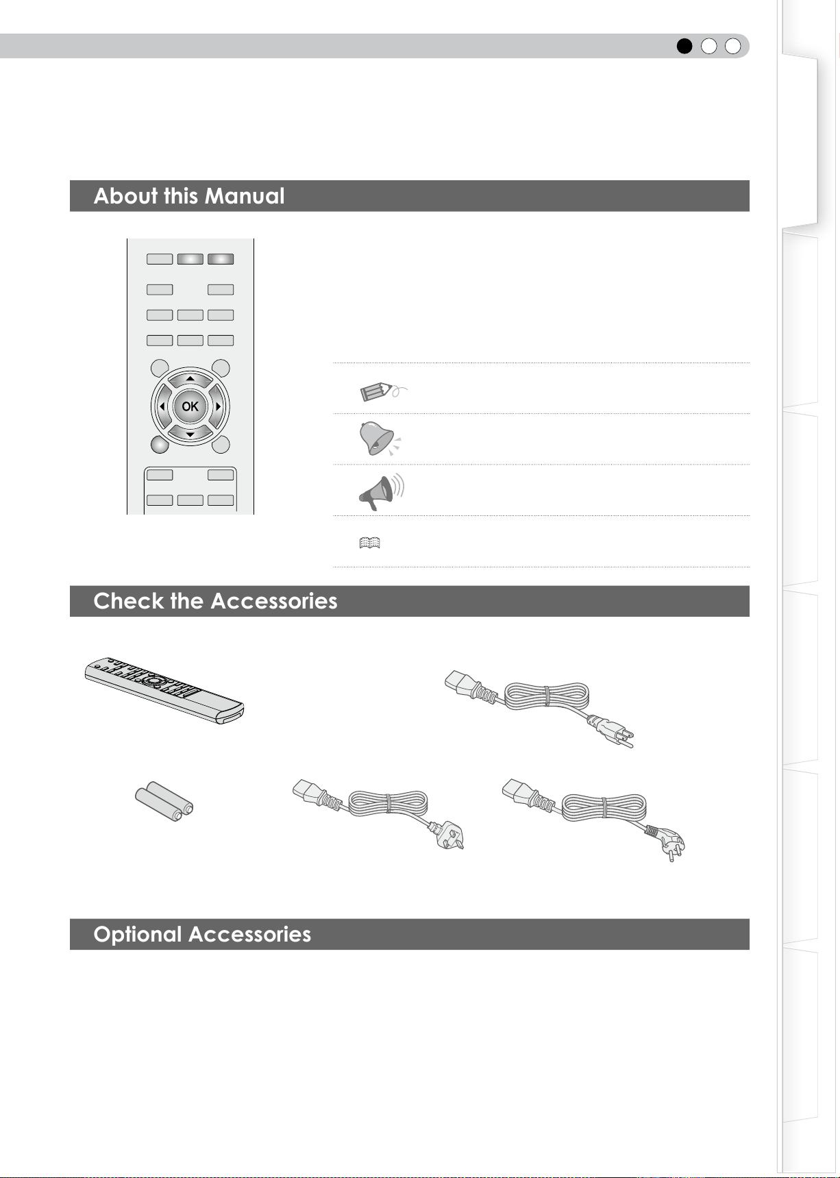
How to Read this Manual/
Accessories/Optional Accessories
This manual mainly describes the operating method using the remote control.
● Buttons on the remote control are described as [Button Name].
● Items on the menu are described as “Selection Item”.
■
Conventions in this manual
Buttons to be used are colored in a darker
shade.
● Instruction manual, warranty card and other printed material are also included.
Optional Accessories
Please check with your authorized dealer for details.
● Replacement Lamp: BHL5010-S (Lamp Unit)
● Replacement Filter (black in appearance): PB006560999 (Inner Filter)
Replacement Filter (white in appearance): PB006575099 (Inner Filter)
About this Manual
Describes the limitations of the functions or usage.
Indicates good-to-know information.
Describes operational precautions.
P13 Indicates relevant pages for reference.
BACK
TEST
HIDE
BRIGHT
CONT
SHARP
COLOR
TINT
N.R
GAMMA
C.TEMP
INFO
LENS.AP
ASPECT
MENU
CINEMA1
CINEMA2
NATURAL
DYNAMIC
STAGE
Remote Control
The power cord supplied varies depending on the destination.
Power Cord
For UK (2m)
AAA size Batteries
(for operation conrmation)
For the US market (X1):
For the EU market (X2):
Power Cord
For European continent countries (2m)
Power Cord
For USA (2m)
Check the Accessories
1
Getting started
14
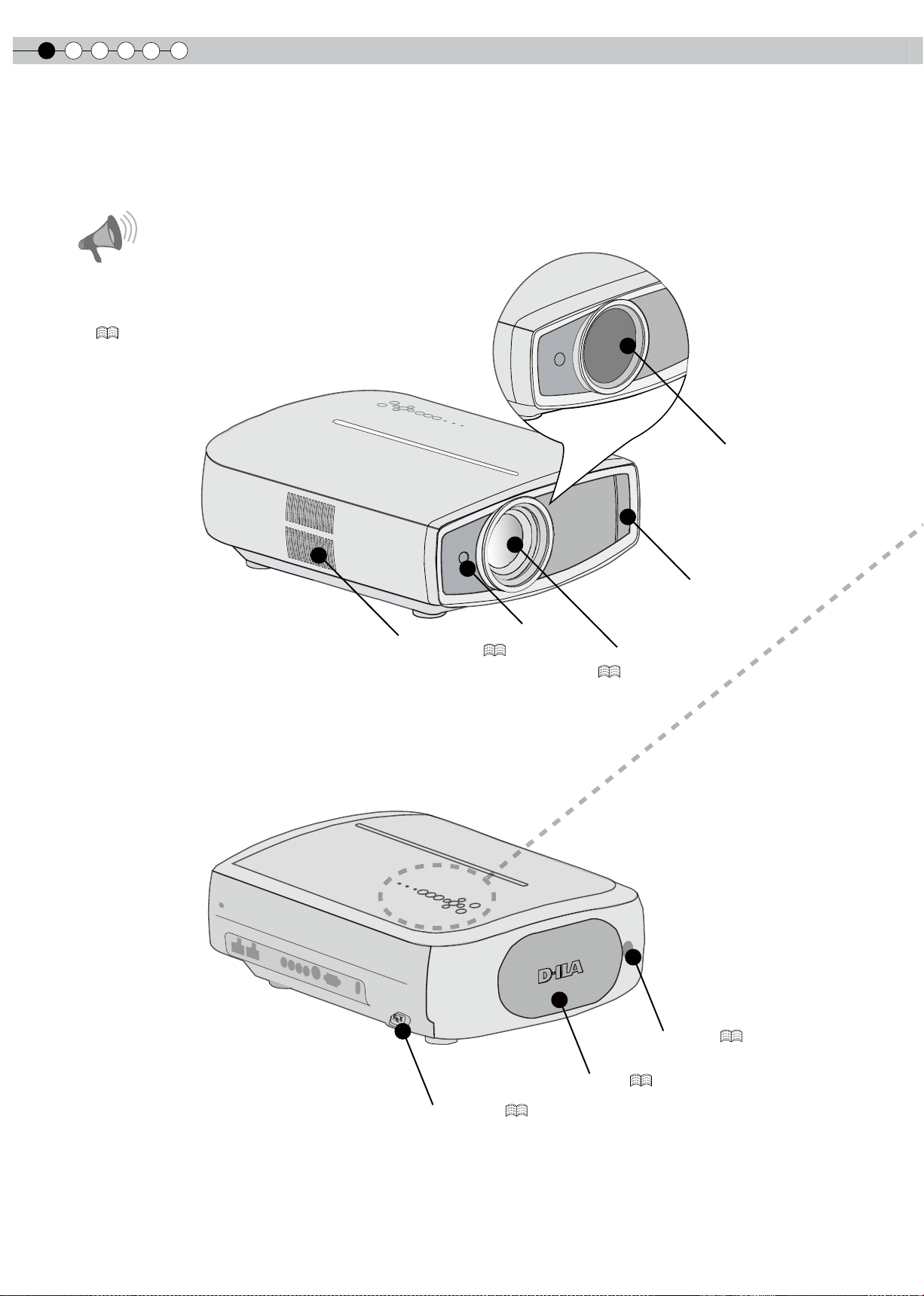
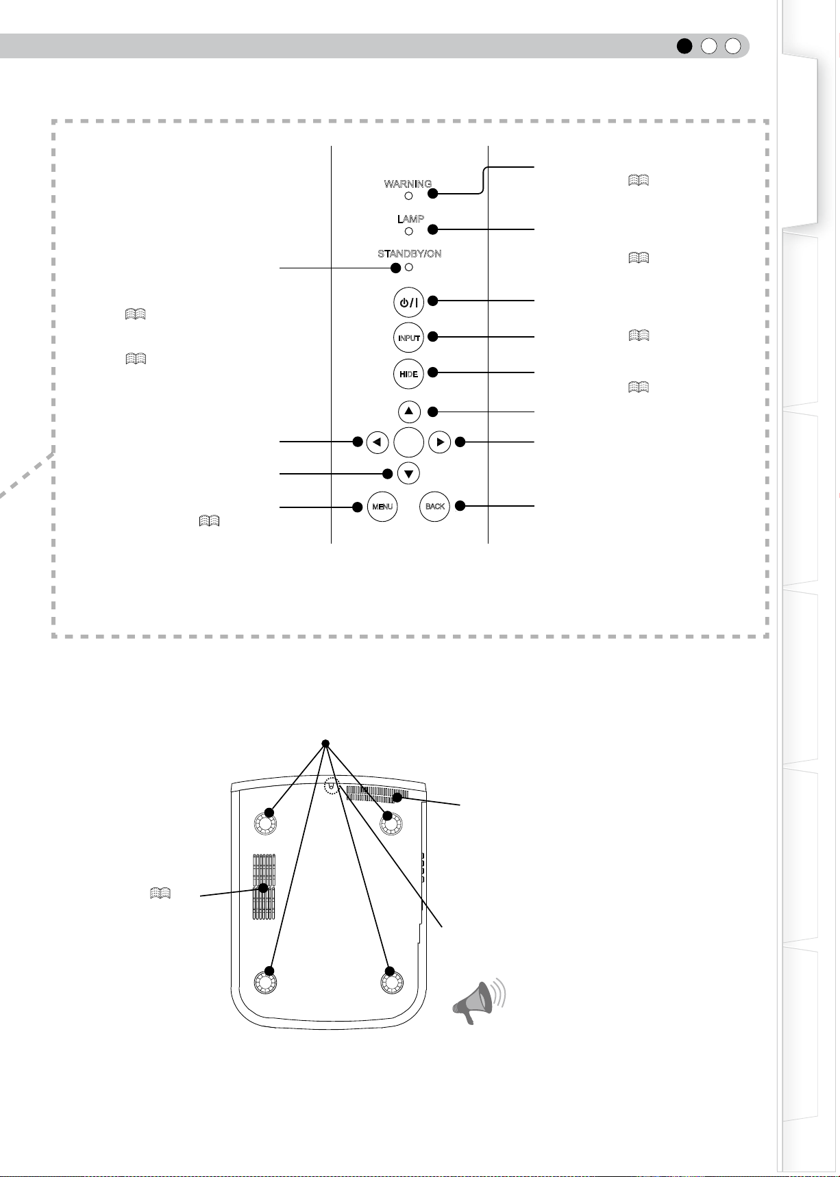
■
Front Side/Left Side
■
Rear Side/Top Side/Right Side
Controls and features
To connect the power cord (
P24
)
Remote Sensor (
P17
)
Lamp Cover (
P46
)
Exhaust Vent
Remote Sensor
(
P17
)
Air Inlet
Lens Cover (opened)
(
P24
)
Lens Cover
(closed)
CAUTION
●
Do not place your fingers in the gap at the lens
during lens shift adjustment. This may cause injuries
if your ngers are caught in between the gap.
(
P22
)
●
Do not let your ngers or other objects get caught in
between the lens cover while closing the cover. This
can cause injuries or malfunction.
ENGLISH
15
Getting Started
Preparation
Basic Operation
Troubleshooting
Settings
Others
CAUTION
●
Do not close lens cover when projecting. Otherwise
it will cause malfunction
,
heat and re.
■
Bottom Surface
Feet: The height (0 to 5 mm) can be adjusted by turning the foot.
Air inlets
Air inlets/Filter (
P50
)
Light on (Red): Warning mode
(
P45
)
Light on/Blinking (Orange):
Lamp warning
(
P45
)
Light on (Red):
Standby mode
Light on (Green):
During projection
Blinking (Green):
Image is temporarily hidden
(
P25
)
Blinking (Red)
:
Cool Down mode
(
P25
)
To turn on/off the power
To switch input (
P24
)
To hide the image temporarily
(
P25
)
Right button
Left button
Down button
To display the menu
(
P28
)
To return to the previous menu
Up button
WARNING
LAMP
STANDBY/ON
INPUT
HIDE
MENU
BACK
OK
Manual button for lens cover:
Press and hold the button to open the lens cover.
1
Getting started
16
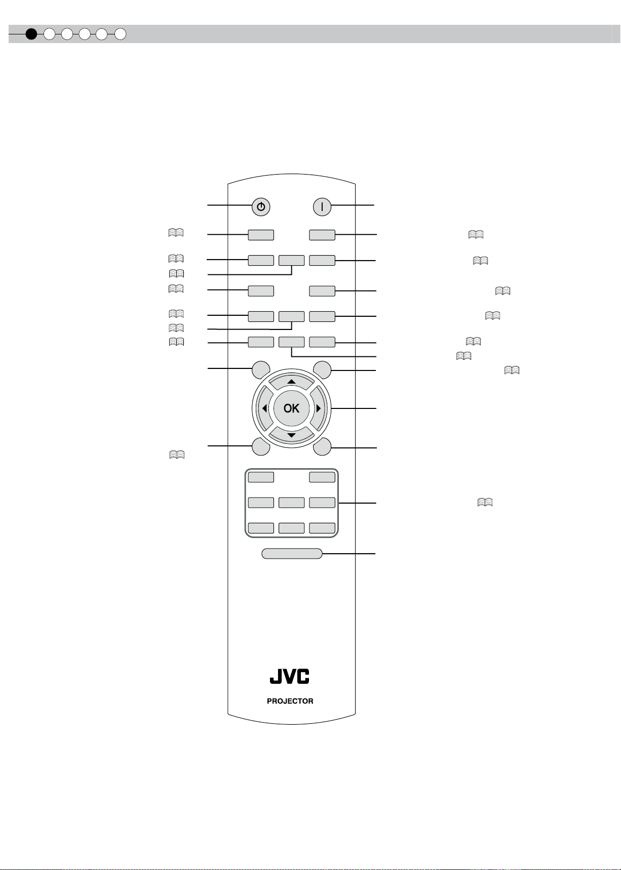
Controls and features (continued)
■
Remote Control
To turn on the power
To turn off the power
To set the screen size (
P26
)
To control lens (
P24
)
To set gamma (
P40
)
To adjust color density (
P40
)
To adjust brightness (
P40
)
To adjust sharpness (
P40
)
To adjust contrast (
P40
)
To display test pattern
To display/close the menu
(
P28
)
To return to the previous menu
BACK
TEST
HIDE
BRIGHT
CONT
SHARP
COLOR
TINT
N.R
GAMMA
C.TEMP
INFO
LENS.AP
ASPECT
LENS
INPUT
STANDBY
ON
MENU
CINEMA1
CINEMA2
NATURAL
STAGE DYNAMIC
USER1
USER2
USER3
RM-MH2GB
LIGHT
To select input mode (
P24
)
To adjust color temperature (
P40
)
To hide the image temporarily (
P25
)
To switch picture mode (
P40
)
To display information (
P39
)
Lens Aperture (
P40
)
To adjust noise reduction (
P40
)
To adjust hue (
P40
)
To select or conrm
To illuminate buttons on the remote control
for 7 seconds
ENGLISH
17
Getting Started
Preparation
Basic Operation
Troubleshooting
Settings
Others
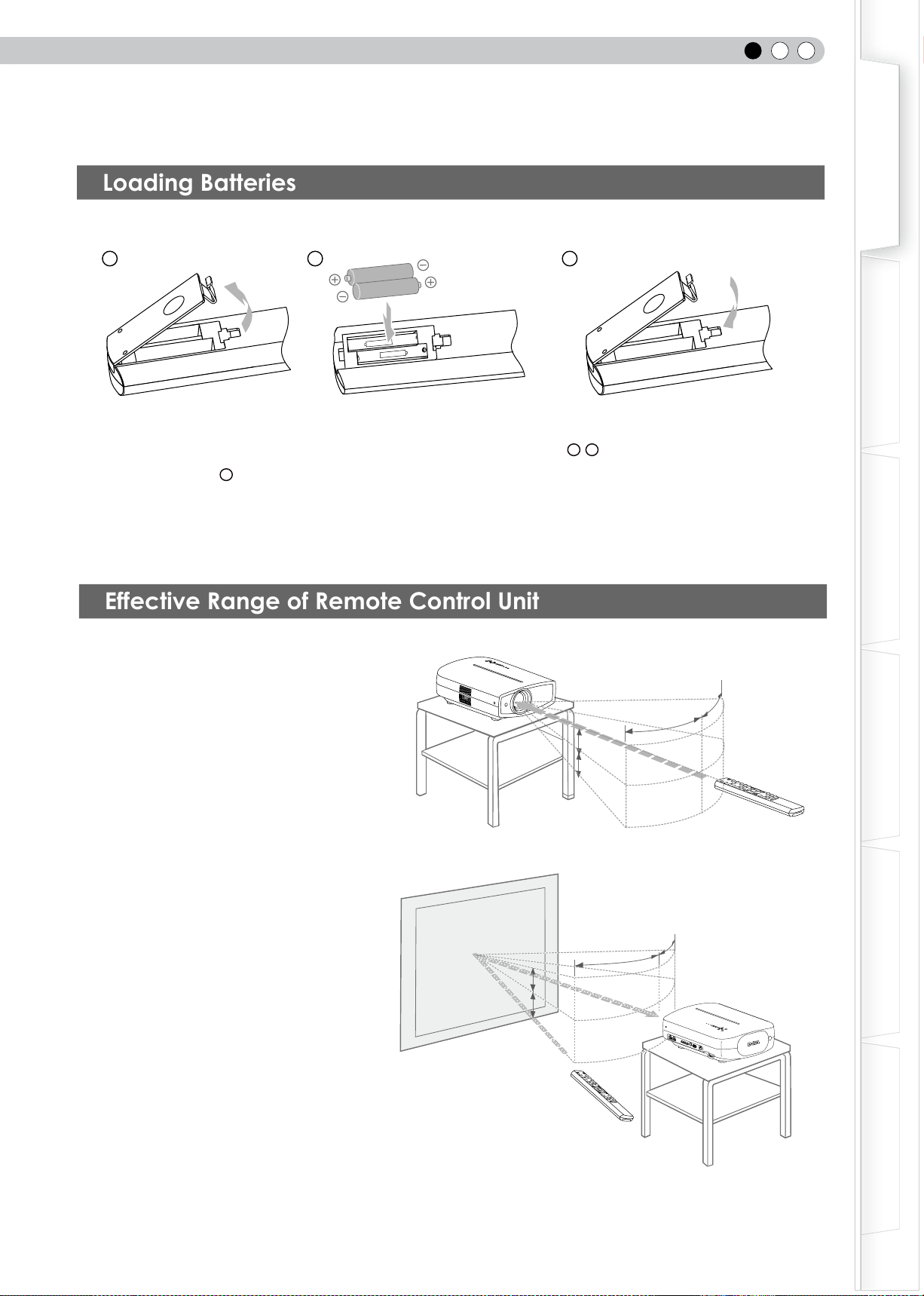
How to Use the Remote control
● If the remote control has to be brought closer to the projector to operate, it means that the batteries are wearing out.
When this happens, replace the batteries. Insert the batteries according to the + - marks.
● Be sure to insert the - end rst.
● If an error occurs when using the remote control, remove the batteries and wait for 5 minutes. Load the batteries again
and operate the remote control.
Effective Range of Remote Control Unit
■
When directing the remote control
toward this unit
● When aiming the remote control towards the
remote sensor on this unit, ensure that the
distance to the sensor in front or at the rear of
this unit is within 7 m.
● If the remote control fails to work properly,
move closer to this unit.
■
When reecting off a screen
● Ensure that the total of distance A between
this unit and screen and distance B between
remote control and screen is within 7 m.
● As the efciency of signals reected from the
remote control unit differ with the type of
screen used, operable distance may decrease.
30°
30°
20°
20°
30°
30°
20°
20°
A
B
Loading Batteries
This unit
Screen
Remote control
Remote control
This unit
1
2 3
2
Preparation
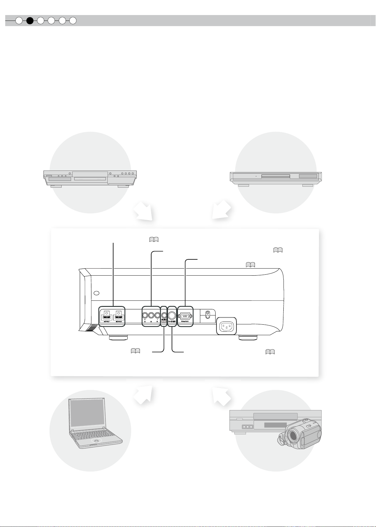
18
Selecting Connecting Devices
● Do not turn on the power until connection is complete.
● The connection procedures differ according to the device used. For details, refer to the instruction manual of the device to be
connected.
● For audio output, connect the device to an amplier.
● The images may not be displayed depending on the devices and cables to be connected.
Use an HDMI compliant cable (sold separately) with the HDMI logo.
● It may not be possible to connect to this unit depending on the dimension of the connector cover of the cables to be
connected.
CB/PB
CR/PR
HDMI 1
HDMI 2
Y
SYNC
S-VIDEO
VIDEO
RS-232C
RBG
To connect via HDMI terminal (
P20
)
To connect RS-232C terminal
(external control) (
P50
)
To connect via component video terminals (
P19
)
To connect via video terminal (
P19
)
To connect via S-video terminal (
P19
)
DVD Recorder
DVD Player
Notebook PC
VCR and camcorder
ENGLISH
19
Getting Started
Preparation
Basic Operation
Troubleshooting
Settings
Others
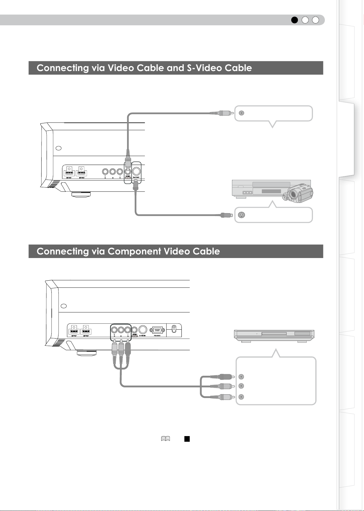
Connecting
Connecting via Component Video Cable
●
Set “COMP.” in the setting menu to “Y Pb/Cb Pr/Cr”. ( P33 -
12
)
Connecting via Video Cable and S-Video Cable
HDMI 1
HDMI 2
VIDEO
S-VIDEO
Y
R
CB/PB
CR/PR
SYNC
BG
RS-232C
This unit
To component video input terminals
Component video cable
(sold separately)
DVD player
C
R
/P
R
(red)
C
B
/P
B
(blue)
Y (green)
Component video output
terminals
HDMI 1
HDMI 2
VIDEO
S-VIDEO
Y
RBG
SYNC
CB/PB
CR/PR
This unit
To video input termina
l
To S-video input terminal
S-video cable
(sold separately)
video cable
(sold separately)
Video output
S-video output
VCR and camcorder
2
Preparation
20
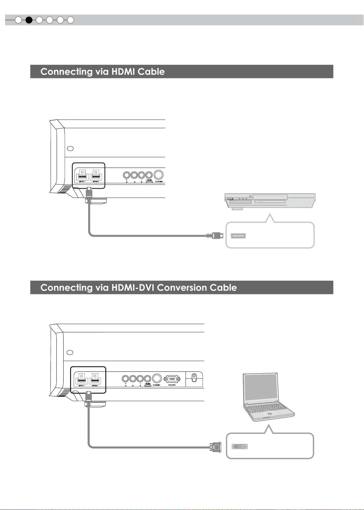
Connecting via HDMI Cable
Connecting via HDMI-DVI Conversion Cable
● If noise is produced, take PCs (including notepads) away from this unit.
HDMI 1
HDMI 2
VIDEO
S-VIDEO
Y
R
SYNC
CB/PB
CR/PR
BG
This unit
HDMI cable (sold separately)
To HDMI 1 or HDMI 2 input terminal
HDMI output terminal
DVD recorder
HDMI 1
HDMI 2
VIDEO
S-VIDEO RS-232C
Y
R
SYNC
CB/PB
CR/PR
BG
This unit
To HDMI 1 or HDMI 2 input terminal
HDMI-DVI conversion cable
(sold separately)
Notebook PC
DVI output terminal
Connecting(Continued)
ENGLISH
21
Getting Started
Preparation
Basic Operation
Troubleshooting
Settings
Others
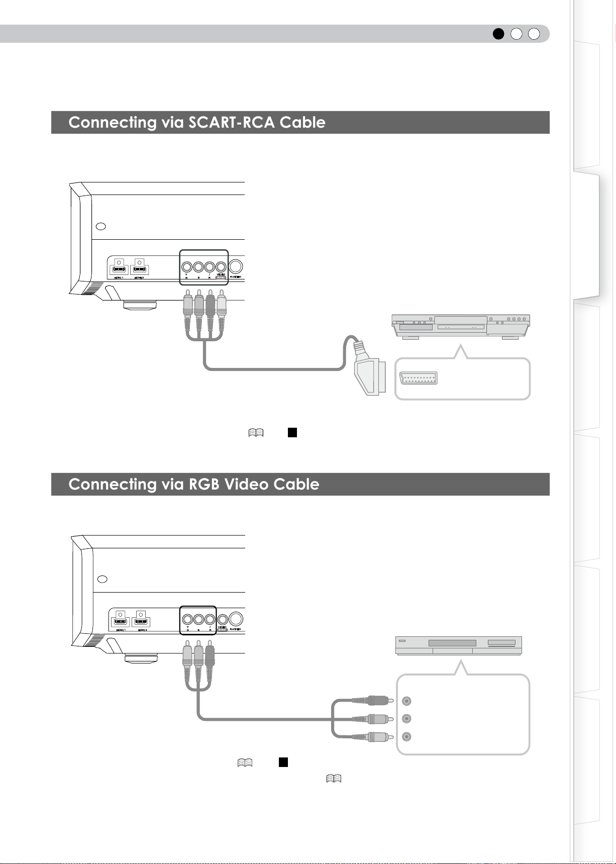
Connecting via SCART-RCA Cable
● Set “COMP.” in the setting menu to “SCART”.( P33 -
12
)
Connecting via RGB Video Cable
● Set “COMP.” in the setting menu to “RGB”.( P33 -
12
)
● For information on compatible input signals, see “Specications”. ( P56)
HDMI 1 HDMI 2
S-VIDEO
RS-232C
Y
R
VIDEO
SYNC
CB/PB
CR/PR
BG
This unit
To RGB video input terminals
RGB video cable
(sold separately)
R(Red)
B(Blue)
G(Green)
(Includes sync signals)
RGB video output terminals
Device equipped with RGB output
HDMI 1 HDMI 2
VIDEO
S-VIDEO
RS-232C
Y
R
SYNC
CB/PB
CR/PR
B
G
This unit
DVD player for European market
SCART terminal
SCART-RCA cable
(sold separately)
To RGB video and
sync signal input terminals
2
Preparation
22
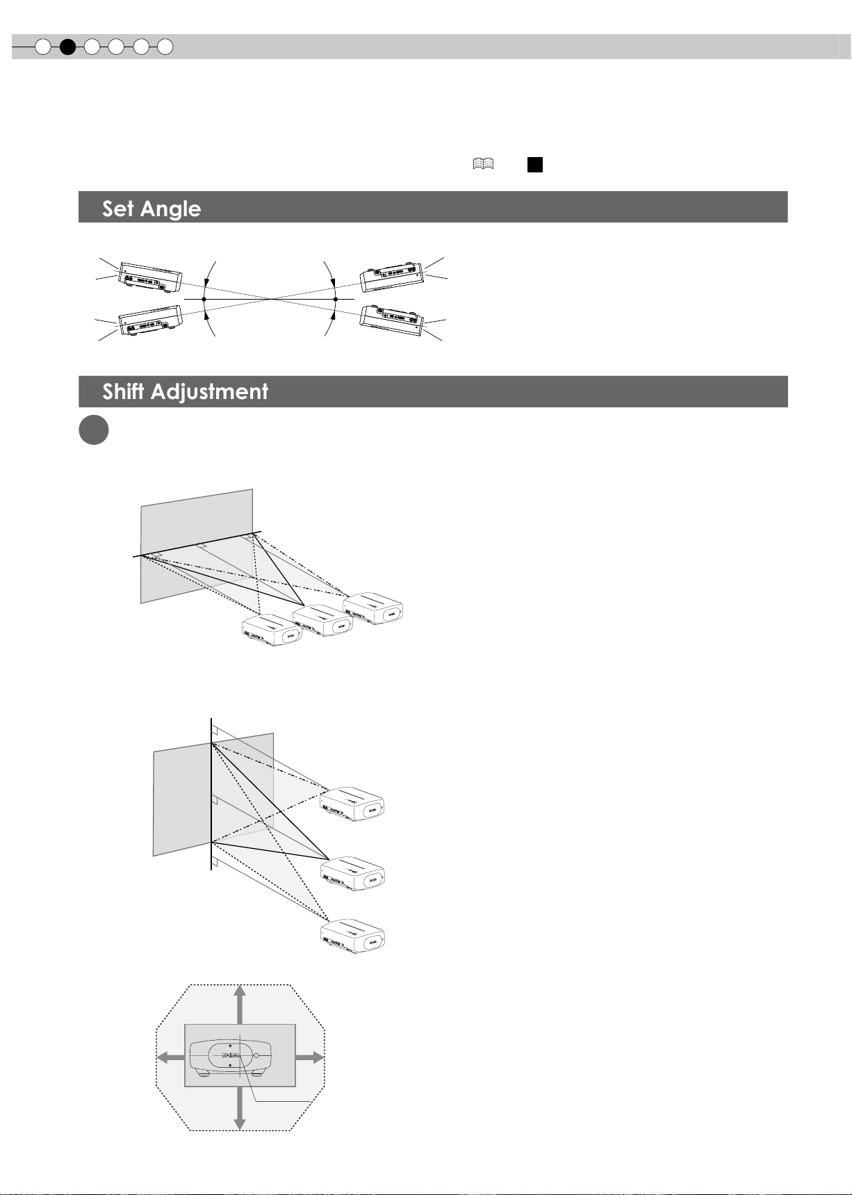
Installing the Projector and Screen
While installing, please place this unit and the screen perpendicular to each other. Failing to do so may
increase trapezoidal distortion. Please refer to “Keystone”. ( P36 -
24
)
Set Angle
● The angle range which can be set for this unit is ±10°.
● Malfunctions may occur if the angle is not set within the above-mentioned range.
Shift Adjustment
1
Installing the projector and screen
■
Left/Right position
* 0% up/down position (center)
■
Up/Down position
* 0% left/right position (center)
■
Shifting range of projected image
10°
10°
10°
10°
80%
34%34%
80%
Lens center
Approximately 34% (maximum) of
the projected image
Approximately 34% (maximum) of
the projected image
Approximately 80% (maximum) of
the projected image
Approximately 80% (maximum) of
the projected image
ENGLISH
23
Getting Started
Preparation
Basic Operation
Troubleshooting
Settings
Others
2
Adjust such that the projected image is in the center of the screen
● It may be necessary to set “Pixel Adjust” in the setting menu after adjusting the image position. ( P36 -
22
)
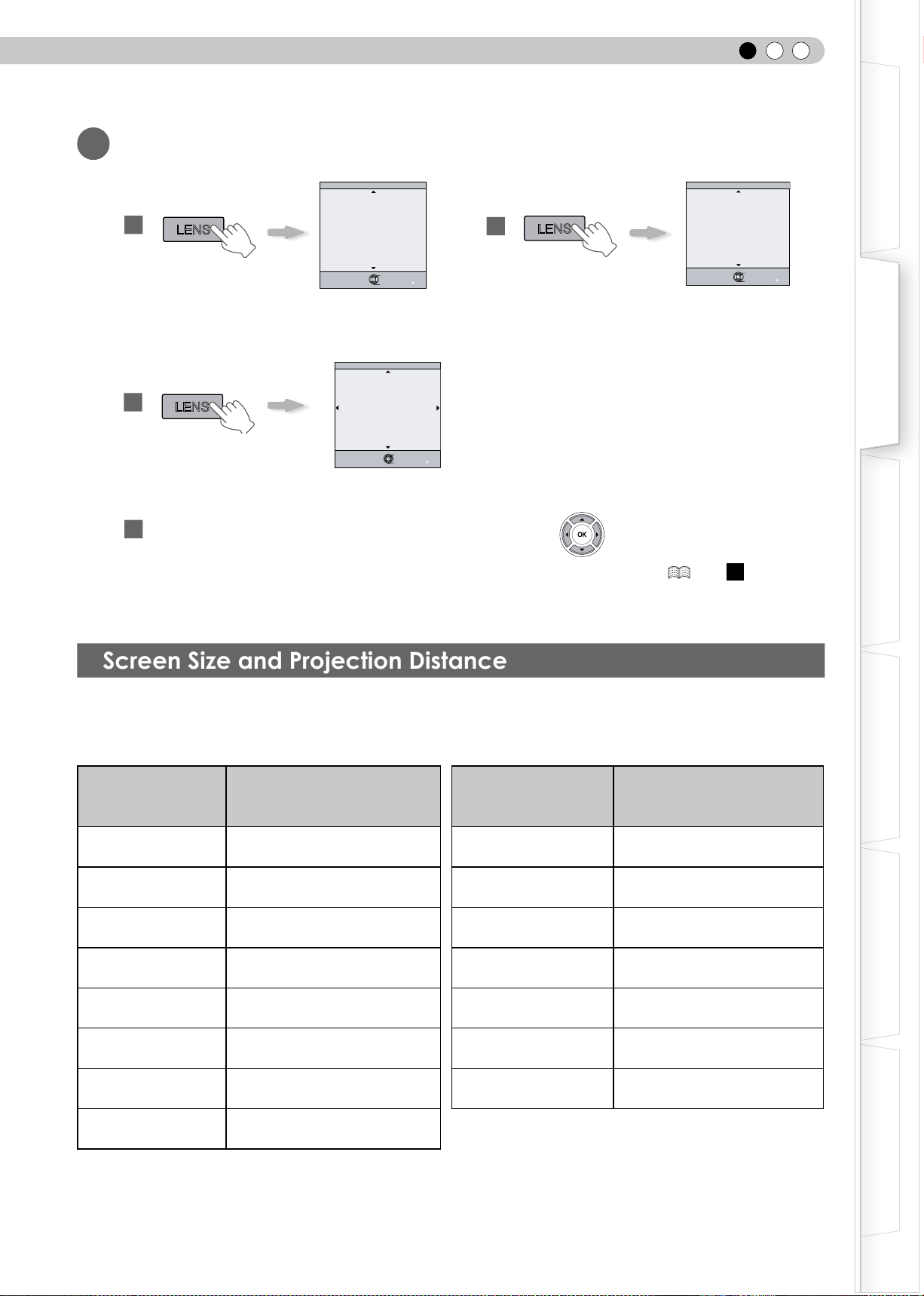
Screen Size and Projection Distance
Determine the distance from the lens to the screen to achieve your desired screen size.
This unit uses a 2.0x power zoom lens for projection.
■
Relationship Between Projection Screen Size and Projection Distance
Projection Screen Size
(Diagonal Length)
Aspect Ratio 16:9
Approximate Projection Distance
W
(
Wide
)
to
T
(
Tele
)
Projection Screen Size
(Diagonal Length)
Aspect Ratio 16:9
Approximate Projection Distance
W
(
Wide
)
to
T
(
Tele
)
60"
(Approx. 1.52m)
Approx. 1.78m to
Approx. 3.66m
140"
(Approx. 3.56m)
Approx. 4.23m to
Approx. 8.60m
70"
(Approx. 1.78m)
Approx. 2.09m to Approx. 4.28m
150"
(Approx. 3.81m)
Approx. 4.53m to
Approx. 9.22m
80"
(Approx. 2.03m)
Approx. 2.40m to
Approx. 4.89m
160"
(Approx. 4.06m)
Approx. 4.84m to
Approx. 9.84m
90"
(Approx. 2.29m)
Approx. 2.70m to
Approx. 5.51m
170"
(Approx. 4.32m)
Approx. 5.14m to
Approx. 10.45m
100"
(Approx. 2.54m)
Approx. 3.01m to
Approx. 6.13m
180"
(Approx. 4.57m)
Approx. 5.45m to
Approx. 11.07m
110"
(Approx. 2.79m)
Approx. 3.31m to
Approx. 6.75m
190"
(Approx. 4.83m)
Approx. 5.75m to Approx. 11.68m
120"
(Approx. 3.05m)
Approx. 3.62m to Approx. 7.36m
200"
(Approx. 5.08m)
Approx. 6.06m to
Approx. 12.30m
130"
(Approx. 3.30m)
Approx. 3.92m to
Approx. 7.98m
● The projection distances in the table are provided only as a guide. Use them as a reference during installation.
● To adjust the installation, use a projected image of aspect ratio 16:9.
Adjust the image position to the center of the screen by pressing (the up, down, left and right buttons).
BACK
Back
Operate
Select
Exit
MENU
Focus
Lens Control
BACK
Back
Operate
Select
Exit
MENU
Zoom
Lens Control
BACK
Back
Operate
Select
Shift
Lens control
LENS
LENS
LENS
1
3
2
4
3
Basic Operation
24
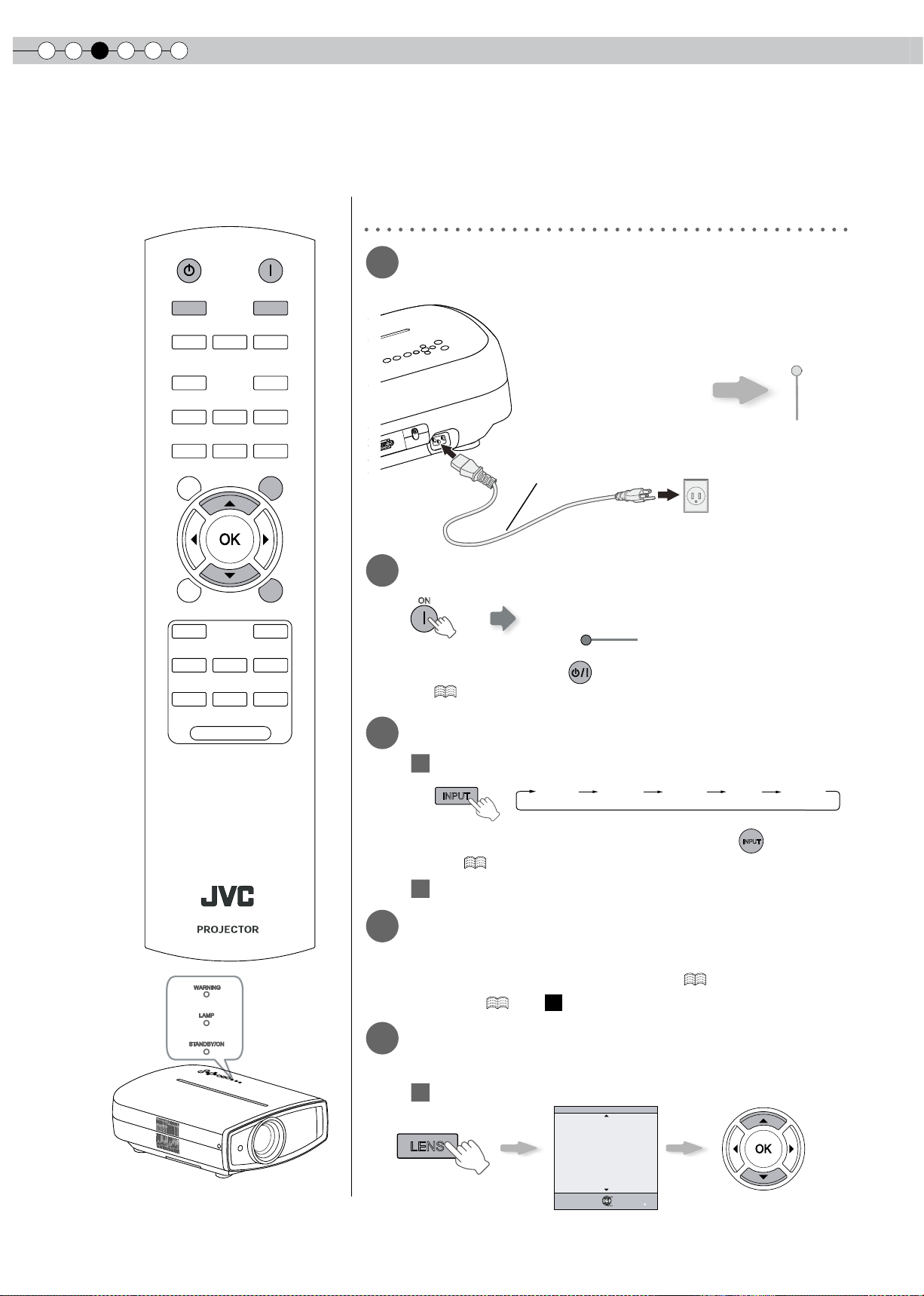
Projecting Image
This section describes the basic operations to project input images on the screen.
Preparation
1
Insert the power plug to the power
outlet
2
Turn on the power
● You can also press the button on the unit to turn on the power.
( P15)
● The lens cover will be opened.
3
Project the image
1
Select input mode
● You can also select the input mode by pressing the
INPUT
button on the
unit. ( P15)
2
Play back the selected device
4
Adjust the position of the projection
screen
● See “Installing the Projector and Screen” ( P22) and “Lens
Control” ( P36 -
21
) for the adjustment method.
5
Adjust the image size (zoom) and the
focus
1
Adjust the focus
WARNING
LAMP
ST ANDBY/ON
① Connect to this unit
② Connect to the power outlet
Light on (Green)
Adjust accordingly by pressing
the up/down buttons
Power Cord
(Supplied)
Light on (Red)
ON
BACK
TEST
HIDE
BRIGHT
CONT
SHARP
COLOR
TINT
N.R
GAMMA
C.TEMP
INFO
LENS.AP
ASPECT
LENS
INPUT
STANDBY
ON
MENU
CINEMA1
CINEMA2
NATURAL
STAGE
DYNAMIC
USER1
USER2
USER3
LIGHT
RM-MH2GB
BACK
Back
Operate
Select
Exit
MENU
Focus
Lens Control
①
②
STANDBY/ON
STANDBY/ON
HDMI 1 HDMI 2 COMP. Video S-Video
LENS
INPUT
ENGLISH
25
Getting Started
Preparation
Basic Operation
Troubleshooting
Settings
Others
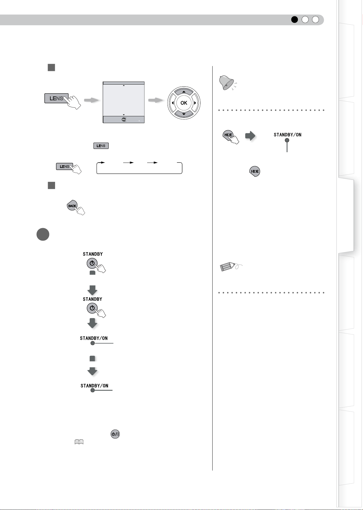
Adjust the image size (zoom)
● Every time the
LENS
button is pressed, the adjustment item
will be switched among “Focus”, “Zoom” and “Shift”.
Focus
Zoom
Shift
LENS
3
To end
6
Turn off the power
● When power off, the lens cover will be closed.
● The power cannot be turned off within approximately 90 seconds
after it has been turned on. Start operation only after 90 seconds
time.
● You can also press the button on the unit to turn off the
power. ( P15)
● Pull out the power plug when the unit will not be used for a
prolonged time.
BACK
You can hide the image temporarily
You can hide the image temporarily.
● Press the
HIDE
button again to display
image.
● The power cannot be turned off when the
image is temporarily hidden.
About Cool Down mode
● The Cool Down mode is a function to
cool down the lamp for approximately 60
seconds after projection is complete. This
function prevents the internal parts of the
unit from deformation or damage due to
overheating of the lamp. It also prevents
lamp blowout and premature shortening
of lamp life.
●
During Cool Down mode, the [STANDBY/
ON] indicator blinks in red.
● After the Cool Down mode is complete,
the unit automatically returns to standby
mode.
● Do not pull out the power plug during
Cool Down mode. This may shorten the
lamp life and cause a malfunction.
HIDE
Adjust accordingly by
pressing the up/down
buttons
Green light blinks
when the image is
hidden.
2
BACK
Back
Operate
Select
Exit
MENU
Zoom
Lens Control
Blinking (Red Lamp)
Light on (Red Lamp)
While a confirmation
screen is displayed
Cool Down mode
LENS
MEMO
TIPS
3
Basic Operation
26
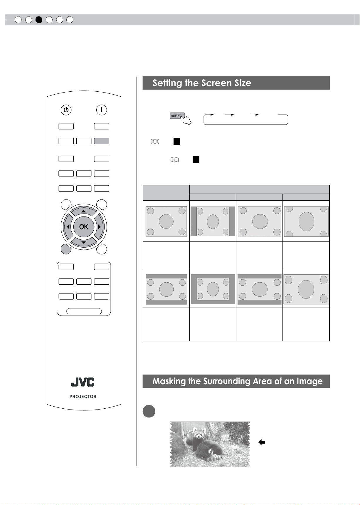
Convenient Features during Projection
You can change the screen size of the projected image or hide the surrounding area of an image for which
quality at the outer area has deteriorated.
Setting the Screen Size
The projected image can be set to a most appropriate screen size
(aspect ratio).
● The screen size can also be set from “Aspect(Video)” of the setting menu.
( P34 -
14
)
● When PC signals are input, the “Aspect(Computer)” setting will be available
instead. ( P34 -
15
)
■
Input Image and Projected Image by Different Screen Size
Settings
Input Image
Screen Size
4:3
16:9 Zoom
SDTV(4:3) Aspect Ratio:
Same
Most appropriate
screen size
Aspect Ratio:
Landscape
Image is stretched
horizontally
Aspect Ratio:
Same
Top and bottom
of the image are
missing
SDTV(4:3)
Image recorded in
landscape (black
bands on top and
bottom) of DVD
software
Aspect Ratio:
Same
Small image is
projected
Aspect Ratio:
Landscape
Image is stretched
horizontally
Aspect Ratio:
Same
Most appropriate
screen size
● Depending on the input image, selecting “4:3” may result in a vertically
stretched image, while selecting “16:9” provides you with the most
appropriate screen size.
Masking the Surrounding Area of an Image
Images for which quality at the outer area has deteriorated can be projected by
masking (hiding) the surrounding area of the projected image.
1
Project the image
ASPECT
4:3 16:9 zoom
Image for which quality
at the outer area has
deteriorated.
BACK
TEST
HIDE
BRIGHT
CONT
SHARP
COLOR
TINT
N.R
GAMMA
C.TEMP
INFO
LENS.AP
ASPECT
LENS
INPUT
STANDBY
ON
MENU
CINEMA1
CINEMA2
NATURAL
STAGE
DYNAMIC
USER1
USER2
USER3
LIGHT
RM-MH2GB
ENGLISH
27
Getting Started
Preparation
Basic Operation
Troubleshooting
Settings
Others
2
Mask the image
1
Display the setting menu
2
Select “Input Signal” “Mask”
3
Set a mask value
Example:
When the “Mask” value is
changed from “Off” “5%”
3
To end
MENU
MENU
Exit
BACK
Back
Select
Operate
0
0
0
0
6500K
2
Normal
Picture Mode
Contrast
Brightness
Color
Tint
Color Temp.
Gamma
Advanced
Lens Aperture
Picture Adjust
Natural
Reset
Video/S-Video
COMP.
Aspect(Video)
Aspect(Computer)
V-stretch
Picture Position
Over scan
Film Mode
Exit
MENU
BACK
Back
Select
Operate
HDMI
16:9
Auto
Auto
Off
Off
Mask
Off
5%
Off
2.5%
Input Signal
自动
Exit
MENU
BACK
Back
Select
Operate
Off
Off
5%
16:9
Video/S-Video
COMP.
Aspect(Video)
Aspect(Computer)
V-stretch
Picture Position
Over scan
Film Mode
HDMI
Auto
Auto
Mask
5%
2.5%
Off
Input Signal
● Masking is available only when high
denition images are input.
MENU
①Select
②Confirm
①Select
②Confirm
MEMO
4
Settings
28
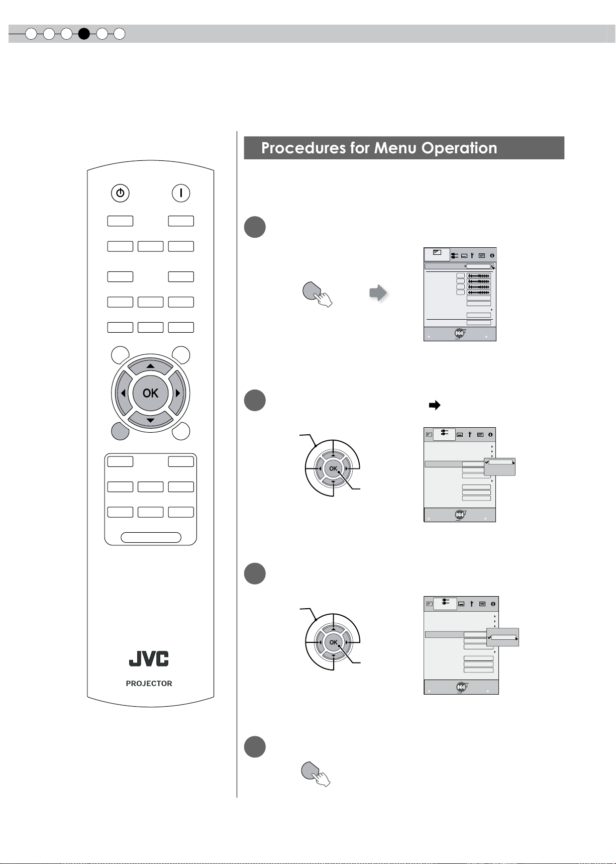
Setting Menu
Projected images can be adjusted to a desired view by changing the initial settings.
Procedures for Menu Operation
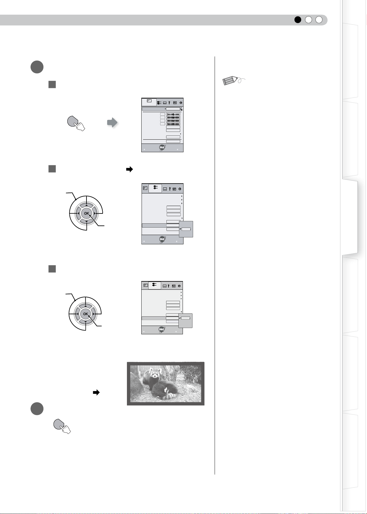
Example:
When changing “Aspect(Video)” from “4:3” to “16:9”
1
Display the setting menu
2
Select “Input Signal” “Aspect(Video)”
3
Set to “16:9”
4
To end
MENU
MENU
Exit
BACK
Back
Select
Operate
0
0
0
0
6500K
2
Normal
Picture Mode
Contrast
Brightness
Color
Tint
Color Temp.
Gamma
Advanced
Lens Aperture
Picture Adjust
Natural
Reset
4:3
4:3
16:9
Zoom
Exit
MENU
BACK
Back
Select
Operate
Off
Off
5%
Video/S-Video
COMP.
Aspect(Computer)
Aspect(
Video
)
V-stretch
Picture Position
Over scan
Film Mode
HDMI
Auto
Auto
Mask
Input Signal
4:3
16:9
16:9
Zoom
Exit
MENU
BACK
Back
Select
Operate
Off
Off
5%
Video/S-Video
COMP.
Aspect(Computer)
Aspect(
Video
)
V-stretch
Picture Position
Over scan
Film Mode
HDMI
Auto
Auto
Mask
Input Signal
MENU
BACK
TEST
HIDE
BRIGHT
CONT
SHARP
COLOR
TINT
N.R
GAMMA
C.TEMP
INFO
LENS.AP
ASPECT
LENS
INPUT
STANDBY
ON
MENU
CINEMA1
CINEMA2
NATURAL
STAGE
DYNAMIC
USER1
USER2
USER3
LIGHT
RM-MH2GB
①Select
②Confirm
①Select
②Confirm
ENGLISH
29
Getting Started
Preparation
Basic Operation
Troubleshooting
Settings
Others
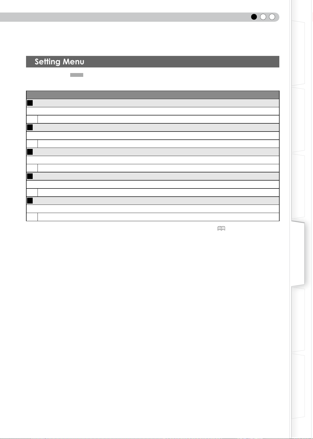
Setting Menu
Item values shown in are factory settings.
● Items that can be congured differ according to the input signals.
Picture Adjust
01
Picture Mode
Adjusts the pattern of the projected image.
Cinema 1, Cinema 2, Natural, Stage, Dynamic, User 1, User 2 and User 3.
02
Contrast
Adjusts the contrast of the projected image.
(Black) –50 to 50 (White)
03
Brightness
Adjusts the brightness of the projected image.
(Darken) –50 to 50 (Brighten)
04
Color
Adjusts the color density of the projected image.
(Lighten) –50 to 50 (Darken)
05
Tint
Adjusts the hue of the projected image.
(Red) –50 to 50 (Green)
● “Contrast”, “Brightness”, “Color” and “Tint” can also be congured from the remote control. ( P16)
4
Settings
30
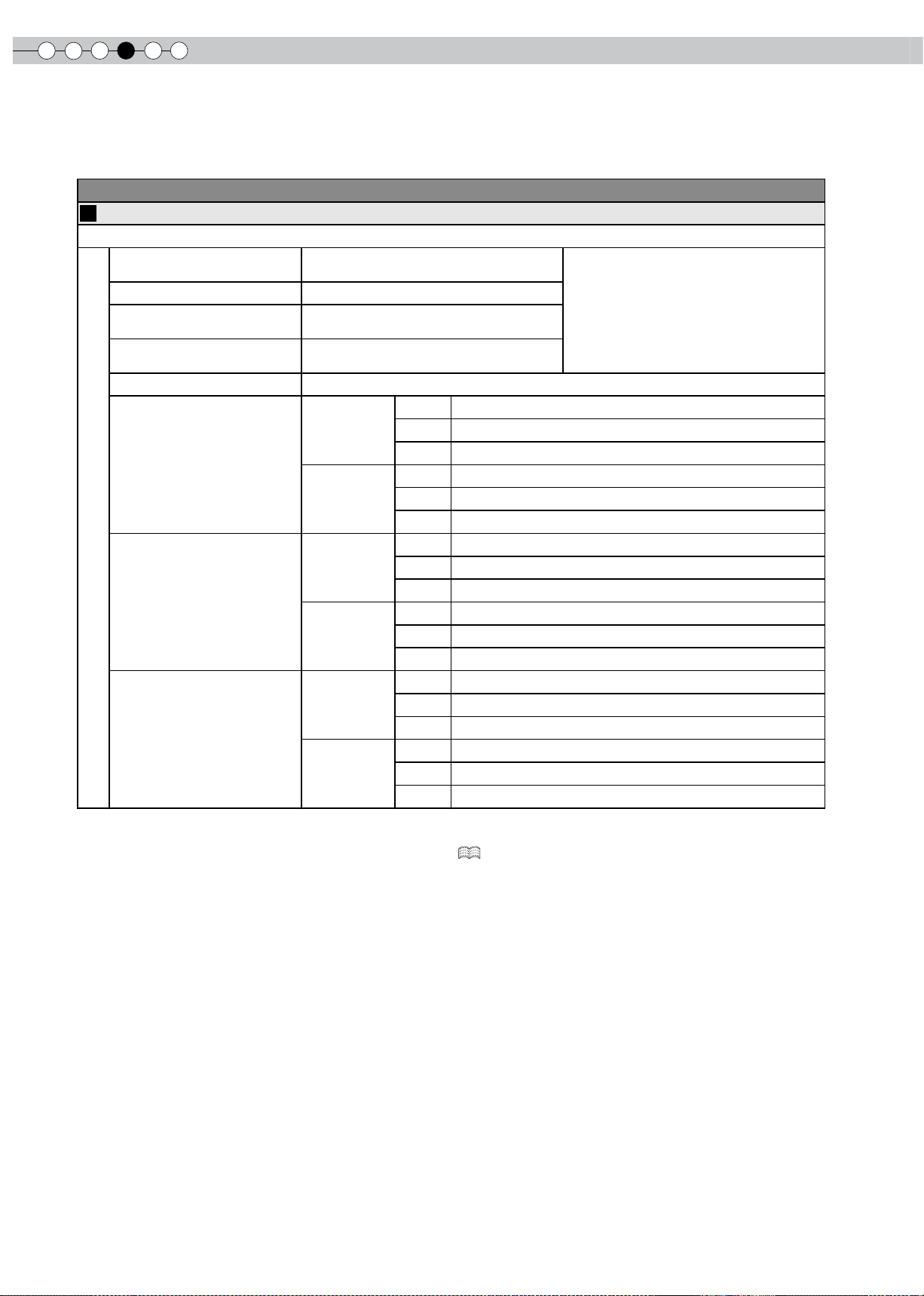
Setting Menu (Continued)
Picture Adjust > Color Temp.
06
Color Temp.
Sets the color temperature of the projected image.
5800K
Select this to give a reddish tinge to the
image.
Only offset can be set.
6500K Select this to have a balanced image.
7500K
Select this to give a bluish tinge to the
image.
9300K
Select this to give a greater bluish tinge
than 7500K.
High Bright Select this to get the brightest image.
Custom 1
Gain
(Bright part)
Red (Less red) –255 to 0 (More red)
Green (Less green) –255 to 0 (More green)
Blue (Less blue) –255 to 0 (More blue)
Offset
(Dark part)
Red (Less red) –50 to 50 (More red)
Green (Less green) –50 to 50 (More green)
Blue (Less blue) –50 to 50 (More blue)
Custom 2
Gain
(Bright part)
Red (Less red) –255 to 0 (More red)
Green (Less green) –255 to 0 (More green)
Blue (Less blue) –255 to 0 (More blue)
Offset
(Dark part)
Red (Less red) –50 to 50 (More red)
Green (Less green) –50 to 50 (More green)
Blue (Less blue) –50 to 50 (More blue)
Custom 3
Gain
(Bright part)
Red (Less red) –255 to 0 (More red)
Green (Less green) –255 to 0 (More green)
Blue (Less blue) –255 to 0 (More blue)
Offset
(Dark part)
Red (Less red) –50 to 50 (More red)
Green (Less green) –50 to 50 (More green)
Blue (Less blue) –50 to 50 (More blue)
● The red, green and blue colors can be adjusted and registered respectively.
● This setting can also be congured from the remote control. ( P16)
Loading...