


DVD VIDEO RECORDER
DR-M10
|
|
|
CABLE/DBS |
|
|
|
|
|
|
|
TV |
DVD |
|
|
|
TV |
|
TV/ |
STANDBY/ON |
|
|
|
|
MUTING VIDEO TV/CBL/DBS |
DVD |
|
|
|
|||
|
|
ABC |
DEF |
TV VOLUME |
|
|
|
GHI |
|
JKL |
MNO |
|
|
|
|
PQRS |
|
TUV |
WXYZ |
CH |
|
|
|
DBS |
|
|
|
|
|
|
|
CANCEL |
|
AUX MEMO/MARK |
|
|
|
|
|
VCR Plus+ PROG/CHECK REC LINK |
TIMER |
|
|
|
|||
TOP MENU |
|
NAVIGATION |
|
|
|
||
|
|
ENTER |
|
|
|
|
|
MENU |
|
|
RETURN |
|
|
|
|
PREVIOUS |
|
|
NEXT |
|
|
|
|
SLOW |
|
PLAY/SELECT SLOW |
|
|
|
||
REC |
|
STOP/CLEAR |
PAUSE |
|
|
|
|
REC MODE LIVE CHECK |
|
|
|
|
|
||
SET UP |
DISPLAY ON SCREEN |
OPEN/ |
|
|
|
||
CLOSE |
|
|
|
||||
|
|
|
|
|
|
|
REC MODE |
|
|
|
|
|
1STANDBY/ON |
|
PULL - OPEN |
|
|
|
PROGRESSIVE |
F1 |
DV |
DV IN |
|
AUDIO |
SUBTITLE |
ANGLE |
SCAN |
||||
|
|
|
|
|
S-VIDEO |
VIDEO L(MONO)-AUDIO-R |
|
INSTRUCTIONS
LPT0964-001A

2 EN
Dear Customer,
Thank you for purchasing the JVC DVD video recorder. Before use, please read the safety information and precautions to ensure safe use of your new unit.
CAUTIONS
The lightning flash with arrowhead symbol, within an equilateral triangle, is intended to alert the user to the presence of uninsulated “dangerous voltage” within the product’s enclosure that may be of sufficient magnitude to constitute a risk of electric shock to persons.
The exclamation point within an equilateral triangle is intended to alert the user to the presence of important operating and maintenance (servicing) instructions in the literature accompanying the appliance.
WARNING:
TO PREVENT FIRE OR SHOCK HAZARD, DO NOT EXPOSE THIS UNIT TO RAIN OR MOISTURE.
CAUTION:
TO PREVENT ELECTRIC SHOCK, MATCH WIDE BLADE OF PLUG TO WIDE SLOT, FULLY INSERT.
ATTENTION:
POUR ÉVITER LES CHOCS ÉLECTRIQUES, INTRODUIRE LA LAME LA PLUS LARGE DE LA FICHE DANS LA BORNE CORRESPONDANTE DE LA PRISE ET POUSSER JUSQU’AU FOND.
Note to CATV system installer:
This reminder is provided to call the CATV system installer’s attention to Article 820-40 of the NEC that provides guidelines for proper grounding and, in particular, specifies that the cable ground shall be connected to the grounding system of the building, as close to the point of cable entry as practical.
POWER SYSTEM:
This unit operates on voltage of AC 110 – 220 Vd, 50/60 Hz with automatic switching.
CAUTION
A UNIT IS A CLASS 1 LASER PRODUCT. HOWEVER THIS UNIT USES A VISIBLE LASER BEAM WHICH COULD CAUSE HAZARDOUS RADIATION EXPOSURE IF DIRECTED. BE SURE TO OPERATE THE UNIT CORRECTLY AS INSTRUCTED.
WHEN THIS UNIT IS PLUGGED INTO THE WALL OUTLET, DO NOT PLACE YOUR EYES CLOSE TO THE OPENING OF THE DISC TRAY AND OTHER OPENINGS TO LOOK INTO THE INSIDE OF THIS UNIT.
USE OF CONTROLS OR ADJUSTMENTS OR PERFORMANCE OF PROCEDURES OTHER THAN THOSE SPECIFIED HEREIN MAY RESULT IN HAZARDOUS RADIATION EXPOSURE.
DO NOT OPEN COVERS AND DO NOT REPAIR YOURSELF. REFER SERVICING TO QUALIFIED PERSONNEL.
CLASS 1 LASER PRODUCT
REPRODUCTION OF LABELS
WARNING LABEL INSIDE OF THE UNIT
OR |

EN 3
IMPORTANT PRODUCT SAFETY INSTRUCTIONS
Electrical energy can perform many useful functions. But improper use can result in potential electrical shock or fire hazards. This product has been engineered and manufactured to assure your personal safety. In order not to defeat the built-in safeguards, observe the following basic rules for its installation, use and servicing.
ATTENTION
Follow and obey all warnings and instructions marked on your product and its operating instructions. For your safety, please read all the safety and operating instructions before you operate this product and keep this booklet for future reference.
INSTALLATION
1. Grounding or Polarization
(A)Your product may be equipped with a polarized alternatingcurrent line plug (a plug having one blade wider than the other). This plug will fit into the power outlet only one way. This is a safety feature.
If you are unable to insert the plug fully into the outlet, try reversing the plug. If the plug should still fail to fit, contact your electrician to replace your obsolete outlet. Do not defeat the safety purpose of the polarized plug.
(B)Your product may be equipped with a 3-wire grounding-type plug, a plug having a third (grounding) pin. This plug will only fit into a grounding-type power outlet. This is a safety feature.
If you are unable to insert the plug into the outlet, contact your electrician to replace your obsolete outlet. Do not defeat the safety purpose of the grounding-type plug.
2. Power Sources
Operate your product only from the type of power source indicated on the marking label. If you are not sure of the type of power supply to your home, consult your product dealer or local power company. If your product is intended to operate from battery power, or other sources, refer to the operating instructions.
3. Overloading
Do not overload wall outlets, extension cords, or integral convenience receptacles as this can result in a risk of fire or electric shock.
4. Power Cord Protection
Power supply cords should be routed so that they are not likely to be walked on or pinched by items placed upon or against them, paying particular attention to cords at plugs, convenience receptacles, and the point where they exit from the product.
5. Ventilation
Slots and openings in the cabinet are provided for ventilation. To ensure reliable operation of the product and to protect it from overheating, these openings must not be blocked or covered.
●Do not block the openings by placing the product on a bed, sofa, rug or other similar surface.
●Do not place the product in a built-in installation such as a bookcase or rack unless proper ventilation is provided or the manufacturer’s instructions have been adhered to.
6. Wall or Ceiling Mounting
The product should be mounted to a wall or ceiling only as recommended by the manufacturer.
ANTENNA INSTALLATION INSTRUCTIONS
1. Outdoor Antenna Grounding
If an outside antenna or cable system is connected to the product, be sure the antenna or cable system is grounded so as to provide some protection against voltage surges and built-up static charges. Article 810 of the National Electrical Code, ANSI/ NFPA 70, provides information with regard to proper grounding of the mast and supporting structure, grounding of the lead-in wire to an antenna discharge unit, size of grounding connectors, location of antenna discharge unit, connection to grounding electrodes, and requirements for the grounding electrode.
2. Lightning
For added protection for this product during a lightning storm, or when it is left unattended and unused for long periods of time, unplug it from the wall outlet and disconnect the antenna or cable system. This will prevent damage to the product due to lightning and power-line surges.
3. Power Lines
An outside antenna system should not be located in the vicinity of overhead power lines or other electric light or power circuits, or where it can fall into such power lines or circuits. When installing an outside antenna system, extreme care should be taken to keep from touching such power lines or circuits as contact with them might be fatal.

4 EN
USE
1. Accessories
To avoid personal injury:
●Do not place this product on an unstable cart, stand, tripod, bracket, or table. It may fall, causing serious injury to a child or adult, and serious damage to the product.
●Use only with a cart, stand, tripod, bracket, or table recommended by the manufacturer or sold with the product.
●Use a mounting accessory recommended by the manufacturer and follow the manufacturer’s instructions for any mounting of the product.
●Do not try to roll a cart with small casters across thresholds or deep-pile carpets.
2. Product and Cart Combination
A product and cart combination should be moved with care. Quick stops, excessive force, and uneven surfaces may cause the product and cart combination to overturn.
3. Water and Moisture
Do not use this product near water—for example, near a bath tub, wash bowl, kitchen sink or laundry tub, in a wet basement, or near a swimming pool and the like.
4. Object and Liquid Entry
Never push objects of any kind into this product through openings as they may touch dangerous voltage points or shortout parts that could result in a fire or electric shock. Never spill liquid of any kind on the product.
5. Attachments
Do not use attachments not recommended by the manufacturer of this product as they may cause hazards.
6. Cleaning
Unplug this product from the wall outlet before cleaning. Do not use liquid cleaners or aerosol cleaners. Use a damp cloth for cleaning.
7. Heat
The product should be situated away from heat sources such as radiators, heat registers, stoves, or other products (including amplifiers) that produce heat.
SERVICING
1. Servicing
If your product is not operating correctly or exhibits a marked change in performance and you are unable to restore normal operation by following the detailed procedure in its operating instructions, do not attempt to service it yourself as opening or removing covers may expose you to dangerous voltage or other hazards. Refer all servicing to qualified service personnel.
2. Damage Requiring Service
Unplug this product from the wall outlet and refer servicing to qualified service personnel under the following conditions:
a.When the power supply cord or plug is damaged.
b.If liquid has been spilled, or objects have fallen into the product.
c.If the product has been exposed to rain or water.
d.If the product does not operate normally by following the operating instructions. Adjust only those controls that are covered by the operating instructions as an improper adjustment of other controls may result in damage and will often require extensive work by a qualified technician to restore the product to its normal operation.
e.If the product has been dropped or damaged in any way.
f.When the product exhibits a distinct change in performance—this indicates a need for service.
3. Replacement Parts
When replacement parts are required, be sure the service technician has used replacement parts specified by the manufacturer or which have the same characteristics as the original part. Unauthorized substitutions may result in fire, electric shock or other hazards.
4. Safety Check
Upon completion of any service or repairs to this product, ask the service technician to perform safety checks to determine that the product is in safe operating condition.
HOW TO USE THIS INSTRUCTION MANUAL
●All major sections and subsections are listed in the Table Of Contents on page 6. Use this when searching for information on a specific procedure or feature.
●The Index on pages 12 – 17 lists frequently-used terms, and the number of the page on which they are used or explained in the manual. This section also illustrates the controls and connections on the front and rear panel, the front display panel and the remote control.
●The mark signals a reference to another page for instructions or related information.
●Operation buttons necessary for the various procedures are clearly indicated through the use of illustrations at the beginning of each major section.
BEFORE YOU INSTALL YOUR NEW UNIT . . .
. . . please read the sections/literature listed below.
●“CAUTIONS” on page 2
●“IMPORTANT PRODUCT SAFETY INSTRUCTIONS” on pages 3 – 4

EN 5
VCR Plus+, C3 and PlusCode are registered trademarks of Gemstar Development Corporation.
The VCR Plus+ system is manufactured under license from Gemstar Development Corporation.
DSSTM is an official trademark of DIRECTV, Inc., a unit of GM Hughes Electronics. DISH NetworkTM is a trademark of Echostar Communications Corporation.
●Manufactured under licence from Dolby Laboratories. “Dolby” and double-D symbol are trademarks of Dolby Laboratories.
●“DTS” and “DTS Digital Out” are trademarks of Digital Theater Systems, Inc.
●This product incorporates copyright protection technology that is protected by method claims of certain U.S. patents and other intellectual property rights owned by Macrovision Corporation and other rights owners. Use of this copyright protection technology must be authorized by Macrovision Corporation, and is intended for home and other limited viewing users only unless otherwise authorized by Macrovision Corporation. Reverse engineering or disassembly is prohibited.
When the equipment is installed in a cabinet or a shelf, make sure that it has sufficient space on all sides to allow for ventilation (10 cm or more on both sides, on top and at the rear).
When discarding batteries, environmental problems must be considered and the local rules or laws governing the disposal of these batteries must be followed strictly.
Failure to heed the following precautions may result in damage to the unit, Remote or disc.
1.DO NOT place the unit —
—in an environment prone to extreme temperatures or humidity.
—in direct sunlight.
—in a dusty environment.
—in an environment where strong magnetic fields are generated.
—on a surface that is unstable or subject to vibration.
2.DO NOT block the unit’s ventilation openings or holes.
(If the ventilation openings or holes are blocked by a newspaper or cloth, etc., the heat may not be able to get out.)
3.DO NOT place heavy objects on the unit or Remote.
4.DO NOT place anything which might spill on top of the unit or Remote.
(If water or liquid is allowed to enter this equipment, fire or electric shock may be caused.)
5.DO NOT expose the apparatus to dripping or splashing.
6.DO NOT use this equipment in a bathroom or places with water. Also DO NOT place any containers filled with water or liquids (such as cosmetics or medicines, flower vases, potted plants, cups, etc.) on top of this unit.
7.DO NOT place any naked flame sources, such as lighted candles, on the apparatus.
8.AVOID violent shocks to the unit during transport.
MOISTURE CONDENSATION
Moisture in the air will condense on the unit when you move it from a cold place to a warm place, or under extremely humid conditions—just as water droplets form on the surface of a glass filled with cold liquid. In conditions where condensation may occur, disconnect the unit’s power plug from the wall and keep it disconnected for a few hours to let the moisture dry, then turn on the unit.
ATTENTION
To mobile phone users:
Using a mobile phone in the vicinity of the unit may cause picture vibration on the TV screen or change the screen to a blue back display.
On placing the unit:
Some TVs or other appliances generate strong magnetic fields. Do not place such appliances on top of the unit as it may cause picture disturbance.

6 EN |
CONTENTS |
DISC INFORMATION |
7 |
About Discs ......................................................... |
7 |
INDEX |
12 |
INSTALLING YOUR NEW UNIT |
18 |
Basic Connections ............................................. |
18 |
S-VIDEO Connection ........................................ |
19 |
Component Video Connection .......................... |
20 |
INITIAL SETTINGS |
21 |
Plug & Play Set .................................................. |
21 |
Language ........................................................... |
22 |
Clock Set ........................................................... |
24 |
Tuner Set ........................................................... |
26 |
Monitor Set ....................................................... |
28 |
Cable Box Control Setting ................................. |
29 |
DBS Receiver Control Setting ............................ |
32 |
PLAYBACK OPERATIONS |
35 |
Basic Playback .................................................. |
35 |
Playback Features .............................................. |
36 |
Live Memory Playback ...................................... |
41 |
Using Play Set Up Menu ................................... |
46 |
Parental Lock .................................................... |
53 |
RECORDING |
57 |
Basic Recording ................................................ |
57 |
Recording Features ............................................ |
58 |
TIMER RECORDING |
60 |
VCR Plus+® Timer Programing .......................... |
60 |
Changing VCR Plus+® Setting ........................... |
62 |
Manual Timer Programing ................................. |
64 |
On-Disc Timer Programing ............................... |
66 |
Satellite Auto Recording .................................... |
71 |
NAVIGATION |
72 |
Library Database DVD Navi .............................. |
72 |
Modify Original Information .............................. |
75 |
Modify Play List Information .............................. |
78 |
Modify Library Information ................................ |
82 |
Playback with MP3/JPEG Navigation ................. |
84 |
EDITING |
86 |
DV Dubbing ...................................................... |
86 |
Edit From A Camcorder ..................................... |
88 |
Edit To Or From Another Recorder .................... |
89 |
Digital Audio Dubbing ...................................... |
90 |
REMOTE |
91 |
Remote Control Functions ................................. |
91 |
SYSTEM CONNECTIONS |
95 |
Connecting To A Dolby Digital Decoder or |
|
An Amplifier With Built-in DTS ...................... |
95 |
SUBSIDIARY SETTINGS |
96 |
Mode Set ........................................................... |
96 |
Format a disc ................................................... |
101 |
Finalize a disc ................................................. |
102 |
Scan Mode Set ................................................. |
103 |
Tray Lock ........................................................ |
103 |
TROUBLESHOOTING |
104 |
GLOSSARY |
108 |
SPECIFICATIONS |
109 |
LIST OF TERMS |
110 |

DISC INFORMATION |
EN 7 |
About Discs
Recordable/playable discs
You can use discs with the following logos for recording and playback.
DVD-RAM |
12 cm: 4.7 GB/9.4 GB |
|
8 cm: 1.4 GB/2.8 GB (VR mode) |
|
Version 2.0 |
|
Version 2.1 |
|
Version 2.1/3x |
|
|
DVD-R |
12 cm: 4.7 GB |
|
8 cm: 1.4 GB |
|
(Video mode) |
|
General Version 2.0 |
|
General Version 2.0/4x |
|
General Version 2.0/8x |
|
|
DVD-RW |
12 cm: 4.7 GB |
|
(Video mode/VR mode) |
|
Version 1.1 |
|
Version 1.1/2x |
|
|
●The above table is based on the information as of February 2004.
●Recording and playback may not be performed with some DVD-RAM, DVD-R/-RW, and CD-R/-RW discs depending on the characteristics and condition of the disc used, leading to unsatisfactory results. Using discs manufactured by JVC is recommended since they have been tested to be compatible with this unit.
DVD-RAM Discs
It is only possible to use discs which conform with DVD-RAM standard Version 2.0 or 2.1.
●It is impossible to record on DVD-RAM discs which do not conform to this standard. If you use a disc formatted under a different standard version, format it on this unit before use.
●It may not be possible to record, play back, edit or dub a DVD-RAM disc even if it conforms to the standard if it was recorded or edited on the devices from other manufacturers or on a PC, or if it has far too many titles, or if there is very little available capacity remaining on the disc.
●DVD-RAM discs recorded on this unit cannot be played back on an incompatible DVD player.
●It is possible to record copy-once programs of digital broadcasts only onto 4.7/9.4 GB DVD-RAM discs (2.8 GB DVD-RAM discs are not compatible).
DVD-R/RW Discs
It is only possible to use DVD-R discs which conform with DVD-R standard Version 2.0.
When a DVD-R/RW disc (Video mode) is finalized ( pg. 102), it can be played back on a standard DVD player as a
DVD VIDEO disc.
When a DVD-RW disc (VR mode) is finalized ( pg. 102), it can be played back on a standard DVD player compatible with the VR mode of DVD-RW discs.
●Use discs labeled “1x SPEED”.
●This unit is not in compliance with DVD-RW Version 1.2.
●This unit is not in compliance with DVD+RW discs.
Before finalizing ( pg. 102) —
— it is possible to record on unrecorded areas of the disc, edit the disc title and program titles, and delete programs.
●Before finalizing it is possible to play or record DVD-R/RW (Video mode) discs only on this unit.
●It is impossible to overwrite recorded areas of DVD-R discs.
●Available recording capacity does not increase even if a recorded program is deleted from a DVD-R disc.
After finalizing ( pg. 102) —
After a DVD-R/RW disc (Video mode) has been finalized, it is possible to play back the recorded programs (video and/or audio) on a standard DVD video player as a DVD VIDEO disc. ● Edited titles are displayed as the “DVD menu” in video mode.
●It is impossible to record, edit or delete the data either in video mode or in VR mode.
●Either in video mode or in VR mode, although the disc can be played back on DVD players from other manufacturers, sometimes it may not be possible to play depending on the disc and recording conditions.
●It is impossible to record on CD-R/RW or DVD-R discs used for authoring.
●It is impossible to record onto DVD-R/RW (Video mode) discs broadcasts that allow you to copy once. The copy once programs can only be recorded onto DVD-RW discs formatted in VR mode.
NOTES:
The following may result if you play back a DVD-R disc recorded on another unit.
●The disc does not play.
●A mosaic pattern (block noise) appears on the screen.
●Video or audio may be dropped out.
●The unit stops during playback.

8 EN |
DISC INFORMATION (cont.) |
Discs for Playback Only
You can use discs with the following logos for playback only.
DVD VIDEO |
Video CD/Super Video CD |
(example of region code |
|
indications) |
|
Audio CD |
CD-R |
CD-DA |
CD-DA/ |
files |
JPEG/MP3 |
|
files |
CD-RW |
CD-ROM |
CD-DA/ |
JPEG/MP3 |
JPEG/MP3 |
files |
files |
|
●Playback may not be performed depending on the characteristics and condition of the disc used.
●DTS Audio CDs can also be played back (An optional DTS decoder is required).
●MP3 and JPEG discs can be played back on this unit only when they have been recorded in the ISO9660 or Joliet format and finalized.
●JPEG files that can be played back on this unit must conform to JFIF/Baseline process, and the maximum resolution of a JPEG file is 3,840 x 2,160 pixels.
●CD-R/RW discs recorded in music CD format need to be finalized to play on this unit.
●Operation and audio quality of this unit are not guaranteed for discs that do not conform to the Compact Disc specification (CD-DA).
Before you play back a CD, check for the CD logo and read the notes on the package to confirm that it conforms to the Compact Disc specification.
●Depending on the intentions of the author of the software, recording conditions of DVD discs and Video CD/SVCD discs may be restricted. Since this unit plays back discs according to the intentions of the author of the software as indicated on the disc, some functions may not operate as commanded.
●When switching from the first layer to the second layer of double-layered DVD VIDEO discs, the image and sound may be momentarily distorted. This is not a malfunction.
●DVD-AUDIO discs compatible with DVD video players can be played.
●Super Audio CDs (SACD) compatible with conventional CD players can be played.
Unplayable Discs
The following types of discs cannot be played using this unit. Do not attempt to play back any kind of disc that is damaged (cracked, warped, or repaired with adhesive tape) or discs in unusual shapes (heart-shaped, octagonal, or other forms). If such discs are accidentally played back, it may cause noise that can lead to speaker damage.
●CD-ROM discs (including PHOTO-CD and CD-G)
●Discs recorded in Packet Write (UDF) format.
●1.3-GB double density CDs (DDCD)
●High density CDs (HDCD)
The following discs also cannot be played back.
●Discs of a region number other than “1”
●DVD-RAM (2.6 GB/5.2 GB)
Region Number
The world is divided into 6 regions for DVD VIDEO discs. DVD VIDEO discs are assigned a region number to indicate which region they may be played back in. A disc cannot be played back on this unit unless the region number of the disc matches that of the unit. The region number for this unit is “1”. Only discs whose region number includes “1” or “ALL” can be played back such as shown below.
Examples of DVD VIDEO labels which can be played back using this unit.
Marks of discs in this instruction manual
|
|
|
|
Allows operation |
|
Allows operation |
|
|
|
|
|
||
|
|
|
|
with a DVD-RAM |
|
with a Video CD/ |
|
|
|
|
disc. |
|
Super Video CD |
|
|
|
|
|
||
|
|
|
|
|
|
(SVCD) disc. |
|
|
|
|
Allows operation |
|
Allows operation |
|
|
|
|
|
||
|
|
|
|
with a DVD-R disc. |
|
with an Audio CD |
|
|
|
|
|
|
disc. |
|
|
|
|
|
|
|
|
|
|
|
Allows operation |
|
Allows operation |
|
|
|
|
|
||
|
|
|
|
with a DVD-RW |
|
with a disc |
|
|
|
|
disc. |
|
including MP3 files. |
|
|
|
|
|
||
|
|
|
|
Allows operation |
|
Allows operation |
|
|
|
|
|
||
|
|
|
|
with a DVD VIDEO |
|
with a disc |
|
|
|
|
|
||
|
|
|
|
disc. |
|
including JPEG files. |
|
|
|
|
|
||
|
|
|
|
|
|
|
EN 9
Recording Medium and Format
DVD-RAM
●Recording and erasing can be performed as many times as possible on a disc.
●Editing can be performed after recording, such as deleting unwanted parts.
●While recording, it is possible not only to start playback of a program currently being recorded, but also to watch another program previously recorded.
DVD-RW (VR mode)
●Recording and erasing can be performed as many times as possible on a disc.
●Editing can be performed after recording, such as deleting unwanted parts.
DVD-RW (Video mode)
●Can be played back on other DVD players.
●New recording can be performed by erasing all the data on a disc once played back.
DVD-R
●Can be played back on other DVD players.
●Suitable when keeping a recorded disc for a long time.
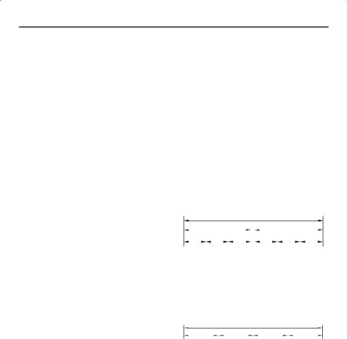
File Structure of Discs
DVD VIDEO
Typically, DVD VIDEO discs are made up of larger units called “titles”. Each title has a number (title number) that can be used to select desired titles. Titles are further divided into units called “chapters”. Each chapter has a number (chapter number) that can also be used to select desired chapters. Note that some discs are not divided into titles and chapters.
When you record a program on a DVD-RAM/RW (VR mode) disc
A single recording session results in a single title (a single chapter). However, chapter marks are automatically inserted when recording is paused, or audio changes from monaural or bilingual to stereo due to commercial breaks, etc. It is also possible to insert chapter marks at desired locations during playback. ( pg. 38)
When you record a program on a DVD-R/RW (Video mode) disc
A single recording session results in a single title (a single chapter). However, chapter marks are automatically inserted when recording is paused, or audio changes due to commercial breaks, etc. It is also possible to insert chapter marks at desired locations during either recording or playback. Once the disc has been finalized, these chapter marks are deleted and new chapter marks are assigned automatically approximately every 5 minutes.
DVD-RAM, DVD-RW, DVD-R or DVD VIDEO disc
|
|
|
|
|
Title 1 |
|
|
|
|
|
|
|
|
|
Title 2 |
|
||||||||
|
|
|||||||||||||||||||||||
Chapter 1 |
|
Chapter 2 |
|
Chapter 3 |
|
|
|
Chapter 1 |
|
Chapter 2 |
|
Chapter 3 |
||||||||||||
|
|
|
|
|
||||||||||||||||||||
|
|
|
|
|
|
|
|
|
|
|
|
|
|
|
|
|
|
|
|
|
|
|
|
|
|
|
|
|
|
|
|
|
|
|
|
|
|
|
|
|
|
|
|
|
|
|
|
|
|
●In Video mode, even before finalizing, it is impossible to perform editing operations other than changing the disc name and/or title names and deleting programs and/or titles.
●After finalizing, it is impossible to perform editing operations.
Audio CD/Video CD/SVCD
Typically, Audio CD discs are divided into separate tracks each containing one song. Each track is assigned a number. For example, the third track is Track 3. The same is true for Video CD/SVCD discs.
However, some discs are not divided into tracks.
Audio CD or Video CD/SVCD
Track 1 |
|
|
Track 2 |
|
|
Track 3 |
|
|
Track 4 |
|||
|
|
|
||||||||||
|
|
|
|
|
|
|
|
|
|
|
|
|

10 EN |
DISC INFORMATION (cont.) |
JPEG/MP3 Disc (CD-R/RW/ROM)
MP3/JPEG files put in directories nested in several levels on a disc will be organized as if they were put in single level directories (groups) by the MP3/JPEG Navigation of this unit. ( pg. 84)
File structure of a disc before starting the MP3/JPEG Navigation
DVD VIDEO Marks
Sometimes marks are printed on a DVD disc and/or on its packaging to indicate information regarding the contents and functions of the disc. Check the marks indicating the contents and functions of the disc. Note, however, that in some cases a disc may not include a mark even for a function it supports.
Directory
MP3 file
JPEG file
File structure of the disc after starting the MP3/JPEG Navigation
Files are automatically grouped as follows and displayed on the MP3/JPEG Navigation screen. Data is displayed in the alphabetical order of file name. Files are grouped based on roots.
●This unit can recognize up to 9 hierarchies including directories and files.
Also, it can recognize up to 250 files in each group, and up to 99 groups on a disc.
NOTES:
●Video CD/SVCD discs that support Playback Control (PBC)
The contents of a disc are recorded into several hierarchies, and played back according to the instructions on the screen while navigating through the hierarchies. It is also possible to playback recorded tracks consecutively without activating the
PBC function even when playing a PBC-compatible disc. ( pg. 40)
●Regarding the contents recorded on discs
Some files may not be played back depending on the file types and other factors.
Marks related to video
Mark |
Description |
Number of subtitles
Number of angles
Recorded under the standard 4:3 aspect ratio
Screen includes black bands at the top and the bottom of image which has a standard 4:3 aspect ratio (letter box)
Video playback is in Wide video mode (16:9) on wide televisions, but in letter box on televisions with standard 4:3 aspect ratio.
Video playback is in Wide video mode (16:9) on wide televisions, but pan and scan is used on televisions with standard 4:3 aspect ratio (either the left or right side of the image is cut-out).
Marks related to audio
Mark |
Description |
Number of audio tracks
Dolby Digital mark
It has been developed by Dolby
Laboratories as a digital surround system.
DTS (Digital Theater Systems)
You can enjoy DTS audio if you connect an amplifier with a built-in DTS decoder to the DIGITAL OUT connector of the unit.
EN 11
Placing a Disc
Opening the disc tray
Press x on the unit or Remote to open the disc tray.
REC MODE LIVE CHECK |
|
|
SET UP |
DISPLAY ON SCREEN |
OPEN/ |
CLOSE |
||
|
|
REC MODE |
|
|
PULL - OPEN |
F1 |
DV |
DV IN |
S-VIDEO |
VIDEO L(MONO)-AUDIO-R |
|
Unit Remote
●Pressing the button on the unit or on the Remote again closes the disc tray.
●Use the buttons on the unit or on the Remote to open and close the disc tray.
●Do not block the disc tray with your hand while it is opening or closing as this may result in hardware failure.
●Do not place unplayable discs or any object other than a disc on the disc tray.
●Do not press down strongly on the disc tray or place any heavy objects on it.
Discs without cartridges
Disc tray
Place the disc on the disc tray with the label side facing up. Since disc size changes depending on the disc to be played back, be sure to correctly align the disc with the grooves for its size. If the disc is not in its groove, it may be scratched or otherwise damaged. To insert an 8 cm disc, place it according to the inner groove.
DVD-RAM discs contained in cartridges
Double-sided discs:
Align the cartridge with the grooves on the disc tray as shown in the illustration and insert with the label side you wish to play back or record facing up. If you insert the disc with label “Side A” facing up, programs are recorded on the side A.
Single-sided discs:
Align the cartridge with the grooves on the disc tray as shown in the illustration and insert with the label side facing up.
NOTE:
To prevent accidental erasure of important recordings, slide the protect tab to the protect position using a ballpoint pen, etc. Release the protect tab to record, edit, or perform other operations.
Care and Handling of Discs
How to handle discs
When handling a disc, do not touch the surface of the
disc. Since discs are made
of plastic, they are easily damaged. If a disc gets dirty, dusty, scratched or warped, the images and sound will
not be picked up correctly,
and such a disc may cause the unit to malfunction.
Label side
Do not damage the label side, stick paper to or use any adhesives on its surface.
Recording side
Make sure that discs are not scratched and dirty on the recording side before use. Scratches and dirt on the recording side of a disc may hinder proper playback and recording.
Storage
Make sure that discs are kept in their cases. If discs are piled on top of one another without their protective cases, they can be damaged. Do not put discs in a location where they may be exposed to direct sunlight, or in a place where the humidity or temperature is high. Avoid leaving discs in your car!
Maintenance of discs
If there are fingerprints or other dirt adhering to a disc, wipe with a soft dry cloth, moving from the centre outwards. If a disc is difficult to clean, wipe with a cloth moistened with water. Never use record cleaners, petrol, alcohol or any anti-static agents.
CAUTION
Sometimes during playback, noise may appear or images may be garbled. This is sometimes due to the disc. (It may not be up to industry standards.)
These symptoms are caused by the discs, not by the malfunction of the unit.
12 EN |
|
|
INDEX |
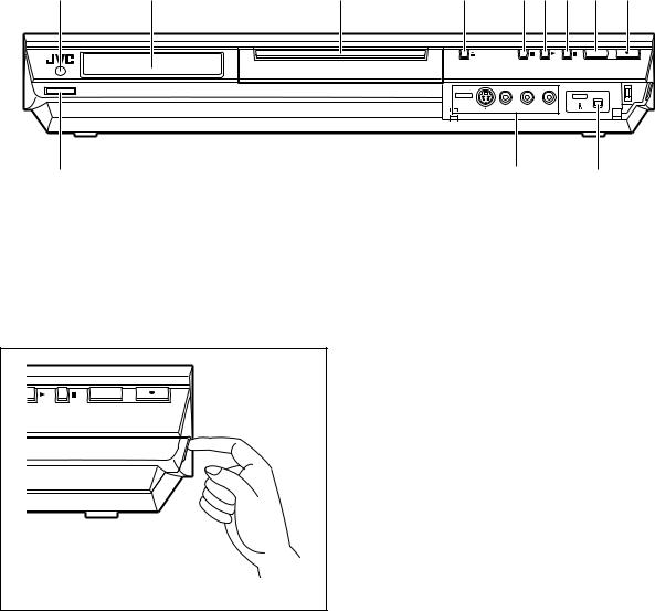
FRONT VIEW |
|
|
|
A |
B |
C |
D EFG H I |
REC MODE
1 STANDBY/ON |
|
|
F1 |
DV |
DV IN |
S-VIDEO |
VIDEO L(MONO)-AUDIO-R |
|
J |
K |
L |
A Infrared Beam Receiving Window B Front Display Panel pg. 14
C Disc Tray
D Open/Close Button (x) pg. 11 E Stop Button (8) pg. 35, 57
F Play Button (4) pg. 35 G Pause Button (9) pg. 35
H Recording Mode Button (REC MODE) pg. 57
I Record Button (7) pg. 57
J Standby/On Button (1 (STANDBY/ON)) K S-video/Video/Audio Input Connectors
(S-VIDEO/VIDEO/AUDIO (L/R)) pg. 88
LDV Input connector (DV IN (i*)) pg. 86
*i (i.Link) refers to the IEEE1394-1995 industry specification and extensions thereof. The i logo is used for products compliant with the i.Link standard.
REC MODE
PULL - OPEN
To access covered connectors, pull and open the connector cover.

EN 13
REAR VIEW
A B C D E F G H I
IN |
Y |
|
|
S-VIDEO |
L-1 |
L-2 |
|
|
|
|
|
VIDEO |
|
|
|
|
|
|
|
|
PB |
S-VIDEO |
|
|
|
VIDEO |
|
|
1 |
|
|
|
|
LEFT |
|
|
|||
|
|
|
L-1 |
|
|
|
|
||
|
|
LEFT |
|
|
|
|
|
||
|
|
|
|
|
|
PCM |
STREAM |
||
OUT |
PR |
AUDIO |
|
|
|
AV COMPU LINK |
|||
|
|
|
|
AUDIO |
|
|
DIGITAL OUT |
||
|
|
RIGHT |
L-2 |
|
|
|
|
|
|
|
|
|
|
|
|
|
|
|
|
|
|
|
|
|
|
RIGHT |
|
|
|
ANTENNA |
COMPONENT |
OUTPUT |
|
INPUT |
CABLE BOX |
OPTICAL |
COAXIAL |
||
J K L M
A Antenna Input Connector (ANTENNA IN)pg. 18
B Component Video Output Connectors (COMPONENT OUTPUT) pg. 20
C Video/Audio Output Connectors (VIDEO/ AUDIO OUTPUT) pg. 18, 19, 20, 89
D S-video Input Connector (S-VIDEO INPUT)pg. 19
E Video/Audio Input Connectors (VIDEO/AUDIO INPUT (L-1/L-2)) pg. 89
F Cable Box Control Connector (CABLE BOX)pg. 29, 32
G AV COMPU LINK Connector pg. 100
H Region Number Label pg. 8 I AC Power Cord pg. 18
J Antenna Output Connector (ANTENNA OUT)pg. 18
K S-video Output Connector (S-VIDEO OUTPUT)pg. 19
LDigital Audio Output Connectors (DIGITAL OUT (COAXIAL/OPTICAL))pg. 90, 95
MCooling Fan
●This prevents the temperature from rising inside the unit. Do not remove it.
●Install the unit so as not to block the area around the fan.
●The cooling fan on the rear of the unit may be activated even if the unit is turned off in the following cases;
—in the REC LINK standby mode ( pg. 71)
—when “AUTO CLOCK” is set to “ON” ( pg. 24)

14 EN |
INDEX (cont.) |
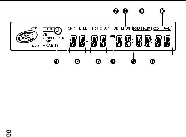
FRONT DISPLAY PANEL
A Disc Type/Status Indicator
When a disc is loaded, the type of the disc is indicated.
When a disc is running, the disc marks rotate. During High-Speed Search: Rotate faster than normal
|
playback. |
During Slow Motion: |
Rotate slower than normal |
|
playback. |
While recording: |
Inner red ring lights in the same |
|
way as normal playback. During |
|
Instant Timer Recording (ITR), |
|
inner red ring slowly blinks. |
While paused: |
Disc marks blink when either |
|
recording or playing back. |
While stopped: |
Disc marks all light. |
While resume stopped: |
Disc marks all blink. |
While the disc tray opened: Disc marks all light out. |
|
No disc on the disc tray: |
Disc marks all light out. |
B VR Mode Indicator pg. 101
Lights when a DVD-RW disc is formatted in VR mode.
C Timer Recording Indicator pg. 60, 64, 66, 69
 : Lights when a disc set up for On-Disc Timer Programing is loaded.
: Lights when timer recording other than On-Disc Timer Programing is on stand-by or being executed.
: Lights when On-Disc Timer Programing is on stand-by or being executed.
: Blinks quickly if you press # (TIMER) in the following cases;
●Disc is not loaded.
●Clock has not been set.
●There is no program setting.
D Recording Mode Indicator (XP/SP/LP/EP/FR)pg. 58
Blinks when recording mode is being set.
While “FR” is blinking, the left 3 digits of the Multi Display (L M) indicate setting values ranging from “60” to “480”. After the value has been set, only “FR” lights.
E Group/Title Indicator (GRP/TITLE) pg. 9, 49
“GRP” or “TITLE” lights depending on a disc loaded while the left 2 digits of the Multi Display (L) indicate the numbers explained below.
“GRP”: Total number of groups or group number being played back are displayed on the Multi Display.
“TITLE”: Total number of titles or title number being played back are displayed on the Multi Display.
F Track/Chapter Indicator (TRK/CHAP) pg. 9, 49
“TRK” or “CHAP” lights depending on a disc loaded while the 3rd and 4th digits from the left of the Multi Display (M) indicate the numbers explained below.
“TRK”: Total number of tracks or track number being played back are displayed on the Multi Display.
“CHAP”: Chapter number being played back are displayed on the Multi Display.
EN 15
G Simulated Surround Effect Indicator (3D)pg. 50
Lights when a simulated surround effect is set to “3D-ON” in Play Set Up menu.
H Linear PCM Indicator (LPCM)
Lights when “XP MODE REC AUDIO” is set to “LINEAR PCM” ( pg. 98) for recording with DVD-RAM, DVD-R and DVD-RW discs, and when Linear PCM audio is played.
I Random/Program Playback Mode Indicator (RND/PRGM)
“RND”: Lights when Random Playback mode is set. ( pg. 52)
“PRGM”: Lights when Program Playback mode is set. ( pg. 52)
J Repeat Mode Indicator ( /1/A–B) pg. 48, 49
Select Repeat Playback mode in Play Set Up menu.
“ |
|
”: |
Whole disc is played back repeatedly. |
“ |
|
1”: |
A single title/chapter/track is played back |
repeatedly.
“ A–B”: The selected part (A–B) is played back repeatedly.
No display: Repeat Playback mode is off.
K Video Output Indicator ( ) pg. 103
No display: Indicates that interlace mode is engaged.  : Indicates that progressive mode is engaged. (Example)
  lights when video output mode is in progressive mode.
L Group/Title Number Display pg. 9, 49 M Track/Chapter Number Display pg. 9, 49 N Remaining Time/Elapsed Time Indicator
pg. 38, 58
Lights when remaining time of DVD-RAM, DVD-R and DVD-RW discs is displayed, and lights out when elapsed time is displayed.
The right 6 digits of the Multi Display (O) indicate elapsed or remaining time of each track.
No display: Indicates elapsed time of the disc. Displayed: Indicates remaining time of the disc.
O Remaining Time/Elapsed Time Displaypg. 38, 58
P Multi Display
Displays clock, received channel, elapsed time, and remaining time.
Also displays status of the unit (NO DISC/OPEN/CLOSE/ READING).

16 EN |
INDEX (cont.) |
ON-SCREEN DISPLAY
When “SUPERIMPOSE” is set to “AUTO” and ON SCREEN on the Remote is pressed in Record mode, various operational indicators appear on the TV screen. To clear the operational indicators, press ON SCREEN again.
A Disc Display
Displays the type of the disc loaded on the disc tray.
B Title Number*
Displays number of the title currently being played back.
C Playback Operation Status Indicator*
Indicates playback operation status by pictographs.
D Playback Time*
Displays playback time of the title currently being played back.
G Chapter Number
Displays playback chapter number during playback, and recording chapter number during recording.
H Clock Display
I Bar Meter Display pg. 43
Displays playback point and other information in bar meter.
J Title Name Display
Displays title name newly registered to the title recorded on DVD-RAM/RW/R discs, or file name of JPEG and MP3 files.
E Recording Mode
Displays recording mode as XP, SP, LP, EP, FR, FR60–FR360, FR420 and FR480. Current recording mode is displayed during recording, and recording mode in which the program was recorded is displayed during playback. The recording mode is not displayed during play list playback.
F Title Number
Displays playback title number during playback, and recording title number during recording.
*During Live Memory playback, playback operation status is displayed. During normal playback, the multichannel encoding method is displayed.
K Operation Status Indicator
Indicates operation status by pictographs. (Also indicates its speed for forward high-speed search, reverse high-speed search and slow motion.)
L Time Display
Displays single title playback elapsed time, single track playback elapsed time, single track remaining time, total elapsed time, total remaining time, and other information in turn.
M Audio Display
Displays audio that is being input.
N Input Display
Displays currently selected input.
EN 17
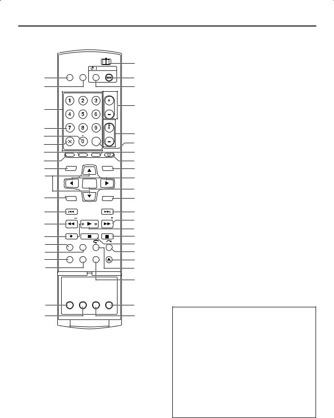
REMOTE
|
|
CABLE/DBS |
U |
|
|
|
TV |
DVD |
|
TV |
TV/ |
STANDBY/ON |
|
|
MUTING VIDEO TV/CBL/DBS |
DVD |
V |
||
A |
|
|
|
|
B |
|
|
|
W |
|
|
ABC |
DEF |
TV VOLUME |
|
C |
GHI |
JKL |
MNO |
|
X |
|
PQRS |
TUV |
WXYZ |
CH |
|
D |
|
|
|
|
Y |
E |
DBS |
|
|
|
|
|
|
|
|
||
F |
CANCEL |
AUX |
MEMO/MARK |
|
Z |
G |
|
a |
|||
|
|
|
|
||
H |
VCR Plus+ PROG/CHECK REC LINK TIMER |
b |
|||
I |
TOP MENU |
|
NAVIGATION |
c |
|
J |
|
d |
|||
|
ENTER |
|
|||
|
|
|
|
||
|
MENU |
|
|
RETURN |
e |
K |
|
|
f |
||
|
|
|
|
||
L |
PREVIOUS |
NEXT |
g |
|
|
|
|
||
|
SLOW |
PLAY/SELECT |
SLOW |
h |
M |
|
|
|
|
|
|
|
i |
|
|
REC |
STOP/CLEAR |
PAUSE |
|
N |
|
|
|
j |
O |
REC MODE LIVE CHECK |
|
k |
|
|
|
|
||
P |
SET UP |
|
OPEN/ |
l |
DISPLAY ON SCREEN CLOSE |
||||
Q |
|
|
|
m |
R |
|
|
|
n |
|
|
|
|
o |
|
AUDIO |
SUBTITLE ANGLE |
PROGRESSIVE |
|
|
SCAN |
|
||
S |
|
|
|
p |
T |
|
|
|
q |
A TV Muting Button (TV MUTING) pg. 92 B TV/VIDEO Button pg. 58
CNumber Keys pg. 36, 53, 57, 60, 91 Character Keys pg. 76
D DBS Button pg. 65
E Auxiliary Button (AUX) pg. 65
F Cancel Button (& (CANCEL)) pg. 60, 69, 85 G Program Check Button (PROG/CHECK) pg. 69 H VCR Plus+ Button pg. 60
I Top Menu Button (TOP MENU) pg. 36 J rt Button pg. 22
K Menu Button (MENU) pg. 36
L Reverse Skip Button (2) pg. 36, 44 Previous Button (PREVIOUS) pg. 40
MReverse Search Button (3) pg. 37, 44 Reverse Slow Button (SLOW –) pg. 37
N Record Button (7 (REC)) pg. 57
O Recording Mode Button (REC MODE) pg. 57
P Live Check Button (LIVE CHECK) pg. 44 Q Set Up Button (SET UP) pg. 22
R Display Button (DISPLAY) pg. 38, 58 S Audio Button (AUDIO) pg. 39
T Subtitle Button (SUBTITLE) pg. 39 U TV/CABLE/DBS/DVD switch pg. 22
VDVD Standby/On Button (DVD 1 (STANDBY/ON))
WTV/CABLE/DBS Standby/On Button (TV/CBL/DBS 1 (STANDBY/ON)) pg. 92
X TV Volume Button (TV VOLUME +/–) pg. 92 Y Channel Button (CH +/–) pg. 94
ZMemo Button (MEMO) pg. 74, 81, 85 Mark Button (MARK) pg. 38
a Satellite Auto Recording Button (REC LINK)pg. 71
b Timer Button (# (TIMER)) pg. 61, 65
c Navigation Button (NAVIGATION) pg. 72 d w e Button pg. 22, 44
e Enter Button (ENTER) pg. 22
f Return Button (RETURN) pg. 40, 60 g Forward Skip Button (6) pg. 36, 44
Next Button (NEXT) pg. 40
h Forward Search Button (5) pg. 37, 44 Forward Slow Button (SLOW +) pg. 37
iPlay Button (4 (PLAY)) pg. 35 Select Button (SELECT)
j Pause Button (9 (PAUSE)) pg. 35, 44
kStop Button (8) pg. 35, 44, 57, 86 Clear Button (CLEAR) pg. 37, 60
l Skip Search Button ( ) pg. 37, 44
m Open/Close Button (x (OPEN/CLOSE)) pg. 11 n One Touch Replay Button ( ) pg. 44, 45
o Play Set Up Button (ON SCREEN)pg. 16, 43, 46
p Progressive Scan Button (PROGRESSIVE SCAN)pg. 103
q Angle Button (ANGLE) pg. 39
How To Use
Before use, insert two AA size batteries into the Remote with the polarity ( and
and  ) matched correctly as indicated on the battery compartment or on the lid.
The Remote can operate most of your unit’s functions, as well as basic functions of TV sets of JVC and other brands.
( pg. 92)
●Point the Remote toward the remote sensor.
●The maximum operating distance of the remote control is about 8 m. (26.25ft)
NOTES:
●When inserting the batteries, be sure to insert in the correct directions as indicated under the battery cover.
●If the Remote doesn’t work properly, remove its batteries, wait for approximately 5 minutes, replace the batteries and then try operating the unit again.

18 EN |
INSTALLING YOUR NEW UNIT |
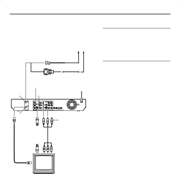
Basic Connections
|
|
|
|
|
Antenna or Cable |
|
|
|
|
Coaxial cable |
|
|
|
|
|
|
Flat feeder |
|
|
Matching transformer |
|||
|
|
(not supplied) |
|
||
ANTENNA |
AUDIO/VIDEO |
AC Outlet |
|||
|
|||||
OUTPUT |
|
|
|||
IN |
|
AC Power Cord |
|||
|
|
|
|
||
IN |
Y |
|
S-VIDEO L-1 |
L-2 |
|
|
|
VIDEO |
|
|
|
|
PB |
S-VIDEO |
|
VIDEO |
1 |
|
|
LEFT |
|||
|
|
LEFT |
L-1 |
|
PCM STREAM |
OUT |
PR |
AUDIO |
|
AV COMPU LINK |
|
|
|
AUDIO |
DIGITAL OUT |
||
|
|
RIGHT |
L-2 |
|
|
|
|
|
|
|
|
|
|
|
|
RIGHT |
|
ANTENNA |
COMPONENT |
OUTPUT |
INPUT |
CABLE BOX |
OPTICAL COAXIAL |
Back of unit
ANTENNA  OUT
OUT
Audio/video cable (supplied)
RF cable
(supplied)
To Audio/video


 input connectors
TV
To 75 ohm
Terminal
It’s essential that your unit be properly connected.
THESE STEPS MUST BE COMPLETED BEFORE ANY VIDEO OPERATION CAN BE PERFORMED.
A Check the contents.
Make sure the package contains all of the accessories listed in “SPECIFICATIONS” on page 109.
B Install the unit.
Place the unit on a stable, horizontal surface.
C Connect the unit to a TV.
A Disconnect the TV antenna from the TV.
BConnect the TV antenna cable to the ANTENNA IN connector on the rear panel of the unit.
C Connect the supplied RF cable between the ANTENNA OUT connector on the rear panel of the unit and the TV’s antenna connector.
DConnect the supplied audio/video cable between the AUDIO/VIDEO OUTPUT connectors on the rear panel of the unit and the TV’s audio/video input
connectors.
●Set your TV to AV mode.
●For switching the TV’s mode, refer to the instruction manual of your TV.
D Connect the unit to power source.
Plug the end of the AC power cord into an AC outlet. This unit performs Plug & Play Set automatically. ( pg. 21)
●The clock and tuner channels will automatically be set when the antenna is connected and when the AC power cord is first connected to an AC outlet. (If “AUTO” and the channel indicator are displayed on the front display panel before the unit is powered on, the clock and tuner channels are being set automatically. Wait for the time to be displayed on the front display panel before turning on the unit.)
NOTES:
●It requires the RF connection to enjoy TV programs.
●The playback image is not displayed without one of the following: A/V, S-Video, or Component Video connection.
Use the conversion plug (provided) depending on the type of your AC WALL outlet.
EN 19
S-VIDEO
Connection
|
|
|
|
|
Antenna or Cable |
|
|
|
|
Coaxial cable |
|
|
|
|
|
|
Flat feeder |
|
|
Matching transformer |
|||
|
|
(not supplied) |
|
||
|
S-VIDEO OUTPUT |
AC Outlet |
|||
ANTENNA |
|
|
|
|
|
|
AUDIO OUTPUT |
|
|||
IN |
|
AC Power Cord |
|||
IN |
Y |
|
S-VIDEO L-1 |
L-2 |
|
|
|
VIDEO |
|
|
|
|
PB |
S-VIDEO |
|
VIDEO |
1 |
|
|
|
L-1 |
LEFT |
|
|
|
LEFT |
|
PCM STREAM |
|
OUT |
PR |
AUDIO |
|
AV COMPU LINK |
|
|
|
AUDIO |
DIGITAL OUT |
||
|
|
RIGHT |
L-2 |
|
|
|
|
|
|
|
|
|
|
|
|
RIGHT |
|
ANTENNA |
COMPONENT |
OUTPUT |
INPUT |
CABLE BOX |
OPTICAL COAXIAL |
ANTENNA |
|
|
|
Back of unit |
|
|
|
|
|
||
OUT |
|
|
|
|
Yellow: |
|
|
|
|
|
Not connected |
S-Video cable |
|
|
Audio/video cable |
||
(not supplied) |
|
|
(supplied) |
||
To S-VIDEO |
|
|
To Audio input |
||
|
|
connectors |
|||
input connector |
|
|
|||
|
|
|
|
||
TV
To 75 ohm
Terminal
8To connect to TV’s S-VIDEO input and AUDIO input connectors
A Connect the unit to a TV.
A Connect the antenna, unit and TV as per “Basic Connections” ( pg. 18).
B Connect the unit’s S-VIDEO OUTPUT connector to the TV’s S-VIDEO input connector.
CConnect the unit’s AUDIO OUTPUT connectors to the TV’s AUDIO input connectors.
B Connect the unit to power source.
Plug the end of the AC power cord into an AC outlet. This unit performs Plug & Play Set automatically. ( pg. 21)
●The clock and tuner channels will automatically be set when the antenna is connected and when the AC power cord is first connected to an AC outlet. (If “AUTO” and the channel indicator are displayed on the front display panel before the unit is powered on, the clock and tuner channels are being set automatically. Wait for the time to be displayed on the front display panel before turning on the unit.)
NOTES:
●You can obtain high-quality S-VHS pictures.
●If your TV is not stereo-capable, use the unit’s AUDIO OUTPUT connectors to connect to an audio amplifier for Hi-Fi stereo sound reproduction.
●For switching the TV’s video input mode, refer to the instruction manual of your television.
20 EN |
INSTALLING YOUR NEW UNIT (cont.) |
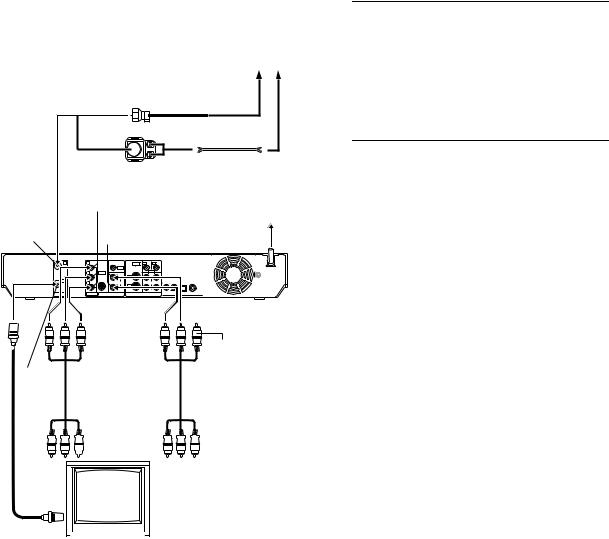
Component Video
Connection
|
|
|
|
|
Antenna or Cable |
|
|
|
|
Coaxial cable |
|
|
|
|
|
|
Flat feeder |
|
|
Matching transformer |
|||
|
|
(not supplied) |
|
||
COMPONENT OUTPUT |
AC Outlet |
||||
|
|
|
|
|
|
ANTENNA |
|
AUDIO OUTPUT AC Power Cord |
|||
IN |
|
||||
IN |
Y |
|
S-VIDEO L-1 |
L-2 |
|
|
|
VIDEO |
|
|
|
|
PB |
S-VIDEO |
|
VIDEO |
1 |
|
|
LEFT |
|||
|
|
LEFT |
L-1 |
|
PCM STREAM |
OUT |
PR |
AUDIO |
|
AV COMPU LINK |
|
|
|
AUDIO |
DIGITAL OUT |
||
|
|
RIGHT |
L-2 |
|
|
|
|
|
|
|
|
|
|
|
|
RIGHT |
|
ANTENNA |
COMPONENT |
OUTPUT |
INPUT |
CABLE BOX |
OPTICAL COAXIAL |
|
|
|
|
|
Back of unit |
|
|
|
|
|
Yellow: |
|
|
|
|
|
Not connected |
ANTENNA |
Component Video |
Audio/video cable |
|||
OUT |
cable |
|
|
|
(supplied) |
|
(not supplied) |
|
|
||
To Component


 Video Input
 connectors
To 75 ohm  Terminal TV
To audio input 

 connectors
Component video connection enables you to obtain high-quality component video pictures.
8To connect to TV’s component video input connectors
A Connect the unit to TV.
APerform A – C in step C in “Basic Connections” ( pg. 18).
B Connect the unit’s COMPONENT OUTPUT connectors to the TV’s component video input connectors.
CConnect the unit’s AUDIO OUTPUT connectors to the TV’s AUDIO input connectors.
B Connect the unit to power source.
Plug the end of the AC power cord into an AC outlet. This unit performs Plug & Play Set automatically. ( pg. 21)
●The clock and tuner channels will automatically be set when the antenna is connected and when the AC power cord is first connected to an AC outlet. (If “AUTO” and the channel indicator are displayed on the front display panel before the unit is powered on, the clock and tuner channels are being set automatically. Wait for the time to be displayed on the front display panel before turning on the unit.)
NOTES:
●If your TV is not stereo-capable, use the unit’s AUDIO OUTPUT connectors to connect to an audio amplifier for Hi-Fi stereo sound reproduction.
●For switching the TV’s video input mode, refer to the instruction manual of your television.
INITIAL SETTINGS |
EN 21 |
Plug & Play Set
Auto Clock Set/Auto Tuner Set
ATTENTION:
●If you use a cable box, Plug&Play will not function; set the clock and tuner channels separately. ( pg. 24 – 27)
●Depending on areas or reception conditions, the unit may not receive the Auto clock setting data from the PBS channel. If this function is taking a considerable amount of time, it may be necessary to perform the Semiauto or Manual Clock Set procedure.
This unit sets the clock and tuner channels automatically when the AC power cord is first connected to an AC outlet. The antenna cable must be connected for the Plug & Play setting.
The time and date can be set automatically by the clock setting data transmitted from one of the regular TV broadcast channels. We call this TV channel the “host channel” and it is a PBS channel in your area.
A Perform Plug & Play setup.
Connect the antenna cable to the unit. ( pg. 18) Then connect the AC power cord to an AC outlet. Do not turn on the unit.
The clock and tuner channels will be set automatically.
NOTES:
|
|
REC MODE |
1STANDBY/ON |
|
PULL - OPEN |
F1 |
DV |
DV IN |
S-VIDEO |
VIDEO L(MONO)-AUDIO-R |
|
●Auto Clock Set is performed first.
“AUTO” blinks on the front display panel during Auto Clock Set.
●Auto Channel Set is performed next. Auto Channel Set scans all the channels that are receivable by your unit. During Auto Channel Set, the channel numbers are displayed as they are scanned and set.
●When Plug & Play setting has been complete successfully, the correct clock time is displayed. If you perform Plug & Play
setting successfully, there is no need to perform “Clock Set” ( pg. 24) and “Tuner Set” ( pg. 26). If, however, you want
to add or delete channels, refer to “Manual Channel Set” ( pg. 27).
●Auto Clock Set does not function properly if the unit is used in areas where no Host PBS signal is available.
During Auto Clock Set |
During Auto Channel Set |
Plug&Play Completed |
“AUTO” blinks. |
The channel numbers are displayed as |
The current time is displayed. |
|
they are scanned and set. |
|
* If an incorrect clock time or “– –:– –” appears on the front display panel, see “What to do if Plug & Play setting failed” below.
INFORMATION
●If “AUTO CLOCK” is set to “ON” ( pg. 24), the clock will be adjusted automatically by the host channel every hour (except 11:00 PM, midnight, 1:00 AM and 2:00 AM) using the incoming PBS channel clock setting data. (This automatic clock
adjustment can only be performed when the unit is turned off. The clock will be adjusted just on these hours — on the time displayed on the front display panel, not on the actual real time.) The default setting of “AUTO CLOCK” is “ON”. ( pg. 24)
●If the memory backup fails, because a power outage occurs or because the AC power cord is unplugged, Plug & Play will be performed when power is restored to the unit.
What to do if Plug & Play setting failed
●If an incorrect time is displayed on the front display panel, you may be receiving the clock setting data of a PBS channel from an adjacent time zone, or an incorrect PBS channel from a cable TV system. In this case, perform “Semiauto Clock Set” ( pg. 24) or “Manual Clock Set” ( pg. 25).
●If “– –:– –” appears on the front display panel, your antenna cable may not be connected to the unit or there may not be a Host PBS signal available in your area. Ensure that the antenna cable is connected correctly. Then turn on and off the unit; the Plug &
Play setting will be automatically reactivated. If Plug & Play setting is not performed though the antenna cable is connected correctly, perform “Manual Clock Set” ( pg. 25) and “Auto Channel Set” ( pg. 26) or “Manual Channel Set” ( pg. 27).

22 EN |
INITIAL SETTINGS (cont.) |
Language
●Turn on the unit.
●Turn on the TV and select the AV mode.
●Slide the TV/CABLE/DBS/DVD switch to DVD.
|
|
CABLE/DBS |
|
|
|
|
TV |
DVD |
|
TV |
TV/ |
STANDBY/ON |
|
|
MUTING VIDEO TV/CBL/DBS DVD |
|
|||
|
ABC |
DEF |
TV VOLUME |
|
GHI |
JKL |
MNO |
|
|
PQRS |
TUV |
WXYZ |
CH |
|
DBS |
|
|
|
|
CANCEL |
AUX |
MEMO/MARK |
|
|
VCR Plus+ PROG/CHECK REC LINK |
TIMER |
|
||
TOP MENU |
|
NAVIGATION |
rtwe |
|
|
ENTER |
|
ENTER |
|
MENU |
|
|
RETURN |
|
|
|
|
||
PREVIOUS |
|
|
NEXT |
|
SLOW |
PLAY/SELECT |
SLOW |
|
|
REC |
STOP/CLEAR |
PAUSE |
|
|
REC MODE LIVE CHECK 
OPEN/
SET UP DISPLAY ON SCREEN CLOSE
AUDIO SUBTITLE ANGLE |
PROGRESSIVE |
SCAN |
On-screen Language Set
This unit offers you the choice to view on-screen messages in 3 different languages.
A Access the Main Menu screen.
Press SET UP.
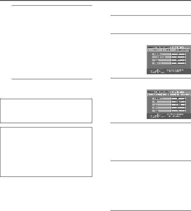
B Access the “DISPLAY SET” screen.
APress w e to move the arrow to “FUNCTION SET
UP”, then press ENTER. B Press w e to move the
arrow to “DISPLAY SET”, then press ENTER.
C Select the desired language.
A Press rt to move the arrow to “ON SCREEN LANGUAGE”, then press ENTER.
BPress rt to select your desired language, then press
ENTER.
D Complete the setting.
Press SET UP.
Menu/Audio/Subtitle Language Set
Some DVD discs contain the DVD menu display, audio and subtitles in multiple languages. With these discs, you can set the default language as you like.
●The procedure shows how to set “MENU LANGUAGE” as an example.
A Access the Main Menu screen.
Press SET UP.
B Access the “LANGUAGE SET” screen.
A Press w e to move the
arrow to “DVD SET UP”, then press ENTER.
B Press w e to move the arrow to “LANGUAGE SET”, then press ENTER.
C Select the desired language.
A Press rt to move the arrow to “MENU LANGUAGE”, then press ENTER.
● See “Language Code List” ( pg. 23).
BPress rt to select your desired language, then press
ENTER.
D Complete the setting.
Press SET UP.
NOTE:
When the selected language is not available on the disc, the disc’s default menu language is played back.

EN 23
Language Code List
AA |
Afar |
|
IK |
Inupiak |
|
RN |
Kirundi |
AB |
Abkhazian |
|
IN |
Indonesian |
|
RO |
Rumanian |
AF |
Afrikaans |
|
IS |
Icelandic |
|
RU |
Russian |
AM |
Ameharic |
|
IW |
Hebrew |
|
RW |
Kinyarwanda |
AR |
Arabic |
|
JI |
Yiddish |
|
SA |
Sanskrit |
AS |
Assamese |
|
JW |
Javanese |
|
SD |
Sindhi |
AY |
Aymara |
|
KA |
Georgian |
|
SG |
Sangho |
AZ |
Azerbaijani |
|
KK |
Kazakh |
|
SH |
Serbo-Croatian |
BA |
Bashkir |
|
KL |
Greenlandic |
|
SI |
Singhalese |
BE |
Byelorussian |
|
KM |
Cambodian |
|
SK |
Slovak |
BG |
Bulgarian |
|
KN |
Kannada |
|
SL |
Slovenian |
BH |
Bihari |
|
KO |
Korean (KOR) |
|
SM |
Samoan |
BI |
Bislama |
|
KS |
Kashmiri |
|
SN |
Shona |
BN |
Bengali, Bangla |
|
KU |
Kurdish |
|
SO |
Somali |
BO |
Tibetan |
|
KY |
Kirghiz |
|
SQ |
Albanian |
BR |
Breton |
|
LA |
Latin |
|
SR |
Serbian |
CA |
Catalan |
|
LN |
Lingala |
|
SS |
Siswati |
CO |
Corsican |
|
LO |
Laothian |
|
ST |
Sesotho |
CS |
Czech |
|
LT |
Lithuanian |
|
SU |
Sundanese |
CY |
Welsh |
|
LV |
Latvian, Lettish |
|
SW |
Swahili |
DZ |
Bhutani |
|
MG |
Malagasy |
|
TA |
Tamil |
EL |
Greek |
|
MI |
Maori |
|
TE |
Telugu |
EO |
Esperanto |
|
MK |
Macedonian |
|
TG |
Tajik |
ET |
Estonian |
|
ML |
Malayalam |
|
TH |
Thai |
EU |
Basque |
|
MN |
Mongolian |
|
TI |
Tigrinya |
FA |
Persian |
|
MO |
Moldavian |
|
TK |
Turkmen |
FJ |
Fiji |
|
MR |
Marathi |
|
TL |
Tagalog |
FO |
Faroese |
|
MS |
Malay (MAY) |
|
TN |
Setswana |
FY |
Frisian |
|
MT |
Maltese |
|
TO |
Tonga |
GA |
Irish |
|
MY |
Burmese |
|
TR |
Turkish |
GD |
Scots Gaelic |
|
NA |
Nauru |
|
TS |
Tsonga |
GL |
Galician |
|
NE |
Nepali |
|
TT |
Tatar |
GN |
Guarani |
|
OC |
Occitan |
|
TW |
Twi |
GU |
Gujarati |
|
OM |
(Afan) Oromo |
|
UK |
Ukrainian |
HA |
Hausa |
|
OR |
Oriya |
|
UR |
Urdu |
HI |
Hindi |
|
PA |
Panjabi |
|
UZ |
Uzbek |
HR |
Croatian |
|
PL |
Polish |
|
VI |
Vietnamese |
HU |
Hungarian |
|
PS |
Pashto, Pushto |
|
VO |
Volapuk |
HY |
Armenian |
|
PT |
Portuguese |
|
WO |
Wolof |
IA |
Interlingua |
|
QU |
Quechua |
|
XH |
Xhosa |
IE |
Interlingue |
|
RM |
Rhaeto-Romance |
|
YO |
Yoruba |
|
|
|
|
|
|
ZU |
Zulu |
|
|
|
|
|
|
|
|
|
|
|
|
|
|
|
|

24 EN |
INITIAL SETTINGS (cont.) |
Clock Set
●Turn on the unit.
●Turn on the TV and select the AV mode.
●Slide the TV/CABLE/DBS/DVD switch to DVD.
|
|
CABLE/DBS |
|
|
|
|
TV |
DVD |
|
TV |
TV/ |
STANDBY/ON |
|
|
MUTING VIDEO TV/CBL/DBS |
DVD |
|
||
|
ABC |
DEF |
TV VOLUME |
|
GHI |
JKL |
MNO |
|
|
PQRS |
TUV |
WXYZ |
CH |
|
DBS |
|
|
|
|
CANCEL |
AUX |
MEMO/MARK |
|
|
VCR Plus+ PROG/CHECK REC LINK |
TIMER |
|
||
TOP MENU |
|
NAVIGATION |
rtwe |
|
|
ENTER |
|
ENTER |
|
MENU |
|
RETURN |
||
|
|
|||
PREVIOUS |
|
|
NEXT |
|
SLOW |
PLAY/SELECT SLOW |
|
||
REC |
STOP/CLEAR |
PAUSE |
|
|
REC MODE LIVE CHECK |
|
|
||
SET UP DISPLAY ON SCREEN |
OPEN/ |
|
||
CLOSE |
|
|||
AUDIO SUBTITLE ANGLE |
PROGRESSIVE |
SCAN |
Perform clock setting only if the clock has not been set correctly by the Plug&Play setting.
Semiauto Clock Set
You can change the host channel/D.S.T. (Daylight Saving Time)/ time zone setting manually.
NOTES:
●The time set previously will be erased when “AUTO CLOCK”, “HOST CH”, “D.S.T.” or “TIME ZONE” setting is changed.
●Semiauto Clock Set does not function properly if the unit is used in areas where no Host PBS signal is available.
A Access the Main Menu screen.
Press SET UP.
B Access the “CLOCK SET” screen.
A Press w e to select
“INITIAL SET UP”, then press ENTER.
B Press w e to select “CLOCK SET”, then press
ENTER.
C Set “AUTO CLOCK” to “ON”.
A Press rt to move the arrow to “AUTO CLOCK”, then press ENTER.
B Press rt until “ON” is selected, then press ENTER.
D Select the host channel.
You can either select “AUTO” or enter a PBS channel number.
APress rt to move the arrow to “HOST CH”, then press ENTER.
BPress rt to select “AUTO” or the desired PBS channel number, then press ENTER.
NOTE:
Some PBS channels do not transmit clock setting data.
E Select the D.S.T. mode.
APress rt to move the arrow to “D.S.T.”, then press
ENTER.
BPress rt to select the desired setting, then press
ENTER.
AUTO: Select if you want to adjust your unit’s clock automatically by the incoming signal from the host channel. Be sure to select the correct time zone manually in step F.
ON: Adjustment will be made by the built-in clock itself.
OFF: Select when Daylight Saving Time does not apply to you.
EN 25
F Select the time zone.
A Press rt to move the arrow to “TIME ZONE”, then press ENTER.
BPress rt to select “AUTO” or the desired time zone, then press ENTER. Each time you press rt, the time zone changes as follows:
{AUTO{ATLANTIC{EASTERN{CENTRAL{ MOUNTAIN{PACIFIC{ALASKA{HAWAII{ (back to the beginning)
NOTE:
If an incorrect time is displayed by the Plug & Play function, you may be receiving the clock setting data of a PBS channel from an adjacent time zone or from an incorrect PBS channel from a cable TV system. If you selected “AUTO” for the host channel in step D, be sure to select the correct time zone manually.
G Complete the Semiauto Clock Set.
Press SET UP to return to normal screen.
IMPORTANT:
Turn off the unit after performing Semiauto Clock. “AUTO” will appear on the front display panel while the clock is being set. The current clock time will appear automatically when the clock setting is complete.
AUTO DAYLIGHT SAVING TIME
This function enables automatic adjustment of the unit’s clock at the start and end of Daylight Saving Time. With Auto DST activated, —
—on the first Sunday of April at 2:00 AM, the clock is adjusted to 3:00 AM.
—on the last Sunday of October at 2:00 AM, the clock is adjusted to 1:00 AM.
NOTE:
Timer recording may not function correctly at the time Daylight Saving Time is adjusted.
Manual Clock Set
A Access the Main Menu screen.
Press SET UP.
B Access the “CLOCK SET” screen.
A Press w e to select
“INITIAL SET UP”, then press ENTER.
B Press w e to select “CLOCK SET”, then press
ENTER.
C Set “AUTO CLOCK” to “OFF”.
APress rt to move the arrow to “AUTO CLOCK”,
then press ENTER.
B Press rtto select “OFF”, then press ENTER.
D Set time, date and year.
A Press rt to move the arrow to “TIME”, then press
ENTER.
B Press rt until the desired time appears, then press ENTER. Set the date and year in the same way.
●Holding rt changes the time in 30-minute intervals, or changes the date in 15-day intervals.
E Select D.S.T. mode.
APress rt to move the arrow to “D.S.T.”, then press
ENTER.
BPress rt to select the desired setting, then press
ENTER.
ON: Adjustment will be made by the built-in clock itself.
OFF: Select when Daylight Saving Time does not apply to you.
F Start clock.
Press SET UP and normal screen appears.

26 EN |
INITIAL SETTINGS (cont.) |
Tuner Set
●Turn on the unit.
●Turn on the TV and select the AV mode.
●Slide the TV/CABLE/DBS/DVD switch to DVD.
|
|
CABLE/DBS |
|
|
|
|
TV |
DVD |
|
TV |
TV/ |
STANDBY/ON |
|
|
MUTING VIDEO TV/CBL/DBS DVD |
|
|||
|
ABC |
DEF |
TV VOLUME |
|
GHI |
JKL |
MNO |
|
|
PQRS |
TUV |
WXYZ |
CH |
|
DBS |
|
|
|
|
CANCEL |
AUX |
MEMO/MARK |
|
|
VCR Plus+ PROG/CHECK REC LINK |
TIMER |
|
||
TOP MENU |
|
NAVIGATION |
rtwe |
|
|
ENTER |
|
ENTER |
|
MENU |
|
|
RETURN |
|
|
|
|
||
PREVIOUS |
|
|
NEXT |
|
SLOW |
PLAY/SELECT |
SLOW |
|
|
REC |
STOP/CLEAR |
PAUSE |
|
|
REC MODE LIVE CHECK 
OPEN/
SET UP DISPLAY ON SCREEN CLOSE
AUDIO SUBTITLE ANGLE |
PROGRESSIVE |
SCAN |
INFORMATION
The unit selects the correct band (TV or CATV) automatically during Auto Channel Set. The selected band will be displayed on the right side of “BAND” on the Tuner Set screen.
Auto Channel Set
Perform Auto Channel Set only if channels have not been set correctly by the Plug&Play setting.
A Access the Main Menu screen.
Press SET UP.
B Access the “TUNER SET” screen.
A Press w e to select
“INITIAL SET UP”, then press ENTER.
B Press w e to select “TUNER SET”, then press
ENTER.
C Perform Auto Channel Set.
Press rt to move the arrow
to “AUTO CH SET”, then press ENTER. You can automatically set the receivable channels in your area in the order of their
frequencies.
●When Auto Channel Set is complete, “SCAN COMPLETED” appears on the TV screen.
●If the scan was unsuccessful, “SCAN COMPLETED–NO SIGNAL–” appears on screen. Check the connections and start again.
D Complete the setting.
Press SET UP.

EN 27
|
|
|
CABLE/DBS |
|
|
|
|
TV |
DVD |
|
TV |
TV/ |
STANDBY/ON |
|
|
MUTING VIDEO TV/CBL/DBS |
DVD |
||
|
|
ABC |
DEF |
TV VOLUME |
0 – 9 |
GHI |
JKL |
MNO |
|
|
|
|
CH |
|
|
PQRS |
TUV |
WXYZ |
|
|
DBS |
|
|
|
|
CANCEL |
AUX |
MEMO/MARK |
|
VCR Plus+ PROG/CHECK REC LINK |
TIMER |
|
||
TOP MENU |
|
NAVIGATION |
rtwe |
|
|
|
|
|
|
|
ENTER |
|
|
ENTER |
MENU |
|
RETURN |
||
|
|
|||
PREVIOUS |
|
NEXT |
|
|
SLOW |
PLAY/SELECT |
SLOW |
|
|
REC |
STOP/CLEAR |
|
PAUSE |
|
REC MODE LIVE CHECK |
|
|
|
|
SET UP |
DISPLAY ON SCREEN |
OPEN/ |
|
|
CLOSE |
|
|||
AUDIO SUBTITLE ANGLE |
PROGRESSIVE |
SCAN |
Manual Channel Set
You can add the channels you want or delete the channels you do not want manually.
A Access the Main Menu screen.
Press SET UP.
B Access the “TUNER SET” screen.
A Press w e to select
“INITIAL SET UP”, then press ENTER.
B Press w e to select “TUNER SET”, then press
ENTER.
C Access the Manual Channel Set screen.
Press rt to move the arrow to “MANUAL CH SET”, then press ENTER.
D Add or skip the desired channels.
To add channels
A Press rt to move the arrow to “CH”.
B Press the number keys to select a channel number you want to add.
Or press ENTER. Press rt to select a channel
number you want to add, then press ENTER.
C Press rt to move the arrow to “ADD/SKIP”, then press ENTER.
D Press rt to select “ADD”, then press ENTER. E Repeat B – D to add other channels.
To skip channels
APress rt to move the arrow to “CH”, then press
ENTER.
BPress the number keys to select a channel number you want to skip, then press ENTER.
C Press rt to move the arrow to “ADD/SKIP”, then press ENTER.
D Press rt to select “SKIP”, then press ENTER. E Repeat B – D to skip other channels.
E Complete the setting.
Press SET UP.
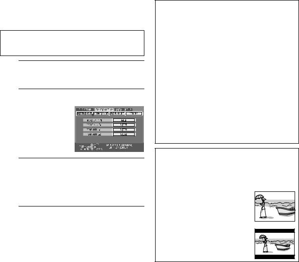
28 EN |
INITIAL SETTINGS (cont.) |
Monitor Set
You can select the monitor type depending on the TV used when you play back DVD VIDEO discs recorded for wide-screen TVs.
●Turn on the unit.
●Turn on the TV and select the AV mode.
●Slide the TV/CABLE/DBS/DVD switch to DVD.
A Access the Main Menu screen.
Press SET UP.
B Access the “VIDEO IN/OUT” screen.
A Press w e to move the
arrow to “FUNCTION SET UP”, then press ENTER.
B Press w e to move the arrow to “VIDEO IN/ OUT”, then press ENTER.
C Select the desired option.
APress rt to select “MONITOR TYPE”, then press
ENTER.
BPress rt to select the desired option, then press
ENTER.
D Complete the setting.
Press SET UP.
(The boldface settings in the table below indicate the settings at your purchase.)
8MONITOR TYPE
4:3LB (Letter Box conversion):
Select this when the aspect ratio of your TV is 4:3 (conventional TV). While viewing a wide screen picture, the black bars appear on the top and the bottom of the screen.
4:3PS (Pan&Scan):
Select this when the aspect ratio of your TV is 4:3 (conventional TV). While viewing a wide screen picture, the black bars do not appear; however, the left and right edges of the pictures will not be shown on the screen.
16:9 AUTO (Wide television conversion):
Select this when the aspect ratio of your TV is 16:9 (wide TV).
16:9 FIX (Wide television conversion):
Select this when the aspect ratio of your TV is fixed to 16:9 (wide TV). The unit automatically adjusts the screen width of the output signal correctly when playing back a picture whose aspect ratio is 4:3.
Pan&Scan/Letter Box
In general, DVD VIDEO disc are produced for a wide-screen TV with 16:9 aspect ratio.
Material with this ratio will not fit to a TV with 4:3 aspect ratio. There are two styles to display the image, “Pan&Scan” (PS) and “Letter Box” (LB).
Pan&Scan
The right and left side of the image are cut off. The image fills the screen.
● The picture will be shown in the “4:3LB” mode depending on the disc even if the “4:3PS” mode is selected.
Letter Box
Black bands appear at the top and bottom of the image. The image itself appears in 16:9 aspect ratio.

EN 29
Cable Box Control
Setting
Place the cable box on top of the unit. Attach the unit’s Controller to the top of the unit with the Controller’s transmitter pointed towards the cable box’s remote sensor.
ATTENTION:
The Controller can also control a DBS receiver. If both a cable box and a DBS receiver are used, position the Controller so its signal reaches the remote sensors of both the cable box and DBS receiver.
Cable box
Your unit
Controller (suggested locations)
Cable box
|
To RF output |
To Audio/ |
|
|
video |
Controller |
|
output |
Transmitter |
|
|
|
|
|
|
|
or |
|
To |
To |
|
AUDIO/ |
|
|
ANTENNA |
|
|
VIDEO |
|
|
IN |
|
|
INPUT |
|
|
|
Your unit
CABLE
BOX
The following procedure is required if you receive your TV channels through a cable box (descrambler). The Controller allows the unit to automatically switch the cable box channel during timer recording. The Controller is effective for recording broadcasts that have been programed using “VCR Plus+® Timer Programing”
( pg. 60) or “Manual Timer Programing” ( pg. 64).
Installing Controller
A Install a Controller.
Place a Controller so that the path between its transmitter and the cable box’s remote sensor is unobstructed.
B Attach the Controller.
Fix securely using the adhesive strip attached on the back of the Controller.
C Make connections.
If your cable box does not have audio/video output connectors
Connect the RF output connector on the cable box to the ANTENNA IN connector on the rear of your unit.
If your cable box has audio/video output connectors
Connect an audio/video cable between the AUDIO/ VIDEO INPUT connectors on the rear of the unit and the audio/video output connectors on the cable box.
NOTE:
When connecting your cable box, refer to its instruction manual.
D Connect the Controller to unit.
Connect the Controller to the CABLE BOX connector on the rear panel.
How to control the cable box
This unit has two separate methods to control your cable box.
●The unit’s wireless Remote can control your cable box. This eliminates the need for a separate cable box’s Remote.
●The unit’s Controller can also control your cable box. This allows the unit to change your cable box’s channel number during timer recording.
Each method must be set up separately. To set up the unit’s Remote, refer to page 93. To set up the Controller, go to page 30.

30 EN |
INITIAL SETTINGS (cont.) |
CABLE/DBS
TV  DVD
DVD
TV TV/ 
 STANDBY/ON
MUTING VIDEO TV/CBL/DBS DVD
|
ABC |
DEF |
TV VOLUME |
GHI |
JKL |
MNO |
|
PQRS |
TUV |
WXYZ |
CH |
DBS |
|
|
|
CANCEL |
AUX |
MEMO/MARK |
|
VCR Plus+ PROG/CHECK REC LINK |
TIMER |
||
TOP MENU |
|
NAVIGATION |
|
|
ENTER |
|
|
MENU |
|
|
RETURN |
PREVIOUS |
|
|
NEXT |
SLOW |
PLAY/SELECT |
SLOW |
|
REC |
STOP/CLEAR |
PAUSE |
|
REC MODE LIVE CHECK 
OPEN/
SET UP DISPLAY ON SCREEN CLOSE
AUDIO SUBTITLE ANGLE |
PROGRESSIVE |
SCAN |
rtwe
ENTER
Setting cable box’s brand and channel
After installation, set the cable box’s brand and channel correctly; otherwise, the Controller cannot work correctly.
●Turn on the unit.
●Turn on the TV and select the AV mode.
●Slide the TV/CABLE/DBS/DVD switch to DVD.
A Turn on the cable box.
Turn on the cable box’s power.
B Access the Main Menu screen.
Press SET UP.
C Access the “CABLE BOX SET” screen.
A Press w e to move the arrow to “INITIAL SET UP”, then press ENTER.
BPress w e to move the arrow to “STB SET”, then
press ENTER.
C Press rt to move the arrow to “CABLE BOX SET”, then press ENTER.
D Select the cable box’s channel.
Your selection depends on how the cable box is connected to your unit.
APress rt to move the arrow to “CABLE BOX OUTPUT CH”, then press
ENTER.
BIf the cable box is
connected to your unit’s ANTENNA IN connector on the rear panel, press rt to select the channel number representing the cable box’s output (CH2 – CH9), then press ENTER.
If the cable box is connected to your unit’s AUDIO/ VIDEO INPUT connectors on the rear panel, press rt to select “L-1” or “L-2”, then press ENTER.
If you do not use a cable box, press rt to select “OFF”, then press ENTER.
 Loading...