


 Loading...
SERVICE MANUAL
DVD VIDEO RECORDER
DR-M10SAA, DR-M10SAG
DR-M10SAX
|
|
TV |
DVD |
TV |
TV/ |
STANDBY/ON |
|
MUTING VIDEO |
TV |
DVD |
|
|
ABC |
DEF |
TV VOLUME |
GHI |
JKL |
MNO |
|
PQRS |
TUV |
WXYZ |
CH |
DBS |
|
|
|
CANCEL |
AUX |
MEMO/MARK |
|
G-CODE PROG/CHECK REC LINK |
TIMER |
||
SHOW VIEW |
|
|
|
TOP MENU |
|
NAVIGATION |
|
|
ENTER |
|
|
MENU |
|
|
RETURN |
PREVIOUS |
|
NEXT |
|
SLOW |
PLAY/SELECT |
SLOW |
|
REC |
STOP/CLEAR |
PAUSE |
|
REC MODE LIVE CHECK |
|
||
SET UP |
|
|
OPEN/ |
DISPLAY ON SCREEN CLOSE |
|||

 STANDBY/ON
PROGRESSIVE
AUDIO SUBTITLE ANGLE SCAN
|
|
Area Suffix |
AA |
Australia |
|
AG ----------- |
Universal Asia |
|
AX -------------- |
Middle East |
|
|
|
|
|
|
|
|
|
|
REC |
|
REC MODE |
LINK |
|
|
|
|
PULL - OPEN |
F1 |
DV |
DV IN |
S-VIDEO VIDEO L(MONO)-AUDIO-R
DR-M10SAA, DR-M10SAG, DR-M10SAX [D4R10]
Since the whole mechanism assembly unit is replaced, the DVD recorder mechanism of this unit need not be adjusted.
TABLE OF CONTENTS
1 PRECAUTION. . . . . . . . . . . . . . . . . . . . . . . . . . . . . . . . . . . . . . . . . . . . . . . . . . . . . . . . . . . . . . . . . . . . . . . . . 1-3 2 SPECIFIC SERVICE INSTRUCTIONS . . . . . . . . . . . . . . . . . . . . . . . . . . . . . . . . . . . . . . . . . . . . . . . . . . . . . . 1-6 3 DISASSEMBLY . . . . . . . . . . . . . . . . . . . . . . . . . . . . . . . . . . . . . . . . . . . . . . . . . . . . . . . . . . . . . . . . . . . . . . . 1-7 4 ADJUSTMENT . . . . . . . . . . . . . . . . . . . . . . . . . . . . . . . . . . . . . . . . . . . . . . . . . . . . . . . . . . . . . . . . . . . . . . . 1-10 5 TROUBLESHOOTING . . . . . . . . . . . . . . . . . . . . . . . . . . . . . . . . . . . . . . . . . . . . . . . . . . . . . . . . . . . . . . . . . 1-11
COPYRIGHT © 2004 Victor Company of Japan, Limited
No.YD025
2004/6
SPECIFICATION
|
|
DR-M10SAA |
DR-M10SAG,DR-M10SAX |
GENERAL |
|
|
|
Power requirement |
AC 220 V - 240 V~, 50 Hz/60 Hz |
AC 110 V -240V~, 50/60 Hz |
|
Power consumption |
Power on : 33 W |
|
|
|
|
Power off : 17.6 W |
|
|
Temperature |
Operating : 5°C to 40°C |
|
|
|
Storage : -20°C to 60°C |
|
Operating position |
Horizontal only |
|
|
Dimensions (W × H × D) |
435 mm × 70 mm × 350 mm |
|
|
|
Weight |
4.3 kg |
|
VIDEO/AUDIO |
|
|
|
Recordable disc |
DVD-RAM |
12 cm : (4.7 GB/9.4 GB) |
|
|
DVD-RAM |
8 cm : (1.4 GB/2.8 GB) |
|
|
DVD-R |
12 cm:( 4.7 GB, 8 cm: 1.4 GB for General Ver. 2.0) |
|
|
DVD-RW |
4.7 GB for Ver. 1.0/1.1 |
|
Recording format |
DVD-RAM |
DVD Video Recording format |
|
|
DVD-R |
DVD-Video format |
|
|
DVD-RW |
DVD-Video format, DVD Video Recording format |
|
|
Recording time |
Maximum 8 hours (with 4.7 GB disc) |
|
|
|
(XP) : Approx. 1 hour, (SP) : Approx. 2 hours, (LP) : Approx. 4 hours, (EP) : Approx. 6 hours, (FR) : Approx. |
|
|
|
1 hour - 8 hours |
|
Playable disc |
DVD-RAM |
12 cm : (4.7 GB/9.4 GB) |
|
|
DVD-RAM |
8 cm : (1.4 GB/2.8 GB) |
|
|
DVD-R |
12 cm:( 4.7 GB, 8 cm: 1.4 GB for General Ver. 2.0) |
|
|
DVD VIDEO, |
4.7 GB |
|
|
DVD-RW |
|
|
|
|
Music CD (CD-DA) |
|
|
|
Video CD |
|
|
|
Super Video CD(SVCD) |
|
|
|
CD-R/RW (CD-DA, Video CD/SVCD formatted discs) |
|
Audio |
recording system |
Dolby Digital (2 ch) |
|
|
|
Linear PCM (XP mode only) |
|
Video recording compression system |
MPEG2 (CBR/VBR) |
|
|
Input/Output |
|
|
|
|
S-video input |
Y : 0.8 - 1.2 Vp-p, 75 Ω |
|
|
|
C : 0.2 - 0.4 Vp-p, 75 Ω |
|
|
S-video output |
Y : 1.0 Vp-p, 75 Ω |
|
|
|
C : 0.3 Vp-p, 75 Ω |
|
|
Video input |
0.5 - 2.0 Vp-p, 75 Ω (pin jack) |
|
|
Video output |
1.0 Vp-p, 75 Ω (pin jack) |
|
|
Audio input |
-8 dB, 50 kΩ (pin jack) Corresponding to mono (left) |
|
|
Audio output |
-8 dB, 1 kΩ (pin jack) |
|
|
i.Link |
4-pin for DV input |
|
Component video output |
Y : 1.0 Vp-p, 75 Ω |
|
|
|
|
PB/PR : 0.7 Vp-p, 75 Ω |
|
|
|
Corresponding to copy protection |
|
|
Optical |
-18 dBm, 660 nm |
|
|
Coaxial |
0.5Vp-p,75ohms Corresponding to Dolby Digital and DTS Digital Surround |
|
|
|
Bit stream |
|
|
|
Selectable in digital audio output setting menu |
|
TUNER/TIMER |
|
|
|
|
Signal system |
PAL-type colour signal and CCIR monochrome signal, 625 lines 50 fields |
|
TV channel storage capacity |
99 positions (+AUX position) |
|
|
|
Tuning system |
Frequency synthesized tuner |
|
Channel coverage |
(low) 42 MHz - 175 MHz/(high) 175 MHz - 470 MHz |
|
|
|
|
UHF 470 MHz - 870 MHz(Adjustable E28 - E60) |
|
Memory backup time |
Approx. 60 min. |
|
|
ACCESSORIES |
|
|
|
Provided accessories |
RF cable, Audio/video cable,Input Cable Adapt- |
RF cable, Audio/video cable,Input Cable Adapter,Output |
|
|
|
er,Output Cable Adapter, Infrared remote control unit, |
Cable Adapter, Infrared remote control unit, "R6" battery × |
|
|
"R6" battery × 2 |
2,Conversion plug |
|
|
|
|
Specifications shown are for SP mode unless otherwise specified.
E.& O.E. Design and specifications subject to change without notice.
•Manufactured under licence from Dolby Laboratories. “Dolby” and double-D symbol are trademarks of Dolby Laboratories.
•“DTS” and “DTS Digital Out” are trademarks of Digital Theater Systems, Inc.
•G-CODE is a trademark of Gemstar Development Corporation and is registered in the following countries: Australia, China, Hong Kong, Japan, South Korea, New Zealand, and Taiwan. SHOWVIEW is a trademark of Gemstar Development Corporation and is registered in the following countries: Austria, Belgium, Czech Republic, Denmark, Finland, France, Germany, Greece, Hungary, Iceland, Italy, Luxembourg, Netherlands, Norway, Poland, Portugal, Russia, Slovakia, South Africa, Spain, Sweden and Switzerland.
The G-CODE/SHOWVIEW system is manufactured under license from Gemstar Development Corporation.
G-CODE and SHOWVIEW are different trademarks used to represent the same easy recording feature. However, for simplicity, only the term G- CODE will be used in the instructions. If you use SHOWVIEW system, follow the same steps listed for the G-CODE system.
•This product incorporates copyright protection technology that is protected by method claims of certain U.S. patents and other intellectual property rights owned by Macrovision Corporation and other rights owners. Use of this copyright protection technology must be authorized by Macrovision Corporation, and is intended for home and other limited viewing users only unless otherwise authorized by Macrovision Corporation. Reverse engineering or disassembly is prohibited.
1-2 (No.YD025)
SECTION 1 PRECAUTION
1.1Safety Precautions
(1)This design of this product contains special hardware and many circuits and components specially for safety purposes. For continued protection, no changes should be made to the original design unless authorized in writing by the manufacturer. Replacement parts must be identical to those used in the original circuits. Services should be performed by qualified personnel only.
(2)Alterations of the design or circuitry of the product should not be made. Any design alterations of the product should not be made. Any design alterations or additions will void the manufacturers warranty and will further relieve the manufacture of responsibility for personal injury or property damage resulting therefrom.
(3)Many electrical and mechanical parts in the products have special safety-related characteristics. These characteristics are often not evident from visual inspection nor can the protection afforded by them necessarily be obtained by using replacement components rated for higher voltage, wattage, etc. Replacement parts which have these special safety characteristics are identified in the Parts List of Service Manual. Electrical components having such features are identified by shading on the schematics and by (  ) on the Parts List in the Service Manual. The use of a substitute replacement which does not have the same safety characteristics as the recommended replacement parts shown in the Parts List of Service Manual may create shock, fire, or other hazards.
(4)The leads in the products are routed and dressed with ties, clamps, tubings, barriers and the like to be separated from live parts, high temperature parts, moving parts and/or sharp edges for the prevention of electric shock and fire hazard. When service is required, the original lead routing and dress should be observed, and it should be confirmed that they have been returned to normal, after reassembling.
(5)Leakage shock hazard testing
After reassembling the product, always perform an isolation check on the exposed metal parts of the product (antenna terminals, knobs, metal cabinet, screw heads, headphone jack, control shafts, etc.) to be sure the product is safe to operate without danger of electrical shock.Do not use a line isolation transformer during this check.
•Plug the AC line cord directly into the AC outlet. Using a "Leakage Current Tester", measure the leakage current from each exposed metal parts of the cabinet, particularly any exposed metal part having a return path to the chassis, to a known good earth ground. Any leakage current must not exceed 0.5mA AC (r.m.s.).
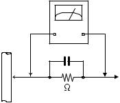
•Alternate check method
Plug the AC line cord directly into the AC outlet. Use an
AC voltmeter having, 1,000Ω per volt or more sensitivity in the following manner. Connect a 1,500Ω 10W resistor paralleled by a 0.15µF AC-type capacitor between an exposed metal part and a known good earth ground.
Measure the AC voltage across the resistor with the AC
voltmeter.
Move the resistor connection to each exposed metal part, particularly any exposed metal part having a return path to the chassis, and measure the AC voltage across the resistor. Now, reverse the plug in the AC outlet and repeat each measurement. Voltage measured any must not exceed 0.75 V AC (r.m.s.). This corresponds to 0.5 mA AC (r.m.s.).
AC VOLTMETER (Having 1000 ohms/volts,
or more sensitivity)
0.15 F AC TYPE
|
Place this |
|
probe on |
1500 10W |
each exposed |
metal part. |
Good earth ground
1.2Warning
(1)This equipment has been designed and manufactured to meet international safety standards.
(2)It is the legal responsibility of the repairer to ensure that these safety standards are maintained.
(3)Repairs must be made in accordance with the relevant safety standards.
(4)It is essential that safety critical components are replaced by approved parts.
(5)If mains voltage selector is provided, check setting for local voltage.
1.3Caution
Burrs formed during molding may be left over on some parts of the chassis.
Therefore, pay attention to such burrs in the case of preforming repair of this system.
1.4Critical parts for safety
In regard with component parts appearing on the silk-screen printed side (parts side) of the PWB diagrams, the parts that are printed over with black such as the resistor (  ), diode (
  ) and ICP (
  ) or identified by the "
  " mark nearby are critical for safety. When replacing them, be sure to use the parts of the same type and rating as specified by the manufacturer.
(This regulation dose not Except the J and C version)
(No.YD025)1-3
1.5Preventing static electricity
Electrostatic discharge (ESD), which occurs when static electricity stored in the body, fabric, etc. is discharged, can destroy the laser diode in the traverse unit (optical pickup). Take care to prevent this when performing repairs.
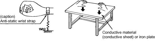
1.5.1Grounding to prevent damage by static electricity
Static electricity in the work area can destroy the optical pickup (laser diode) in devices such as DVD players. Be careful to use proper grounding in the area where repairs are being performed.
(1)Ground the workbench
Ground the workbench by laying conductive material (such as a conductive sheet) or an iron plate over it before placing the traverse unit (optical pickup) on it.
(2)Ground yourself
Use an anti-static wrist strap to release any static electricity built up in your body.
(3)Handling the optical pickup
•In order to maintain quality during transport and before installation, both sides of the laser diode on the replacement optical pickup are shorted. After replacement, return the shorted parts to their original condition.
(Refer to the text.)
•Do not use a tester to check the condition of the laser diode in the optical pickup. The tester's internal power source can easily destroy the laser diode.
1.6Handling the traverse unit (optical pickup)
(1)Do not subject the traverse unit (optical pickup) to strong shocks, as it is a sensitive, complex unit.
(2)Cut off the shorted part of the flexible cable using nippers, etc. after replacing the optical pickup. For specific details, refer to the
replacement procedure in the text. Remove the anti-static pin when replacing the traverse unit. Be careful not to take too long a time when attaching it to the connector.
(3)Handle the flexible cable carefully as it may break when subjected to strong force.
(4)I t is not possible to adjust the semi-fixed resistor that adjusts the laser power. Do not turn it.
1-4 (No.YD025)

1.7Important for laser products
1.CLASS 1 LASER PRODUCT
2.DANGER : Invisible laser radiation when open and inter lock failed or defeated. Avoid direct exposure to beam.
3.CAUTION : There are no serviceable parts inside the Laser Unit. Do not disassemble the Laser Unit. Replace the complete Laser Unit if it malfunctions.
4.CAUTION : The CD,MD and DVD player uses invisible laser radiation and is equipped with safety switches which prevent emission of radiation when the drawer is open and the safety interlocks have failed or are defeated. It is dangerous to defeat the safety switches.
5.CAUTION : If safety switches malfunction, the laser is able
to function.
6.CAUTION : Use of controls, adjustments or performance of procedures other than those specified here in may result in hazardous radiation exposure.
! |
|
Please use enough caution not to |
|||
|
|
|
|
|
|
|
|
see the beam directly or touch it |
|||
|
|
in case of an adjustment or operation |
|||
|
|
check. |
|||
|
|
|
|
|
|
|
|
|
|
|
|
|
|
|
|
|
|
REPRODUCTION AND POSITION OF LABEL and PRINT
WARNING LABEL and PRINT
On mechaism assembly
(No.YD025)1-5
Loading...