


 Loading...
D-ILA PROJECTOR
DLA-VS4010 DLA-VS4810
INSTRUCTIONS
Installation and Connection Started Getting
Thank you for purchasing this JVC product.
Please study this instruction manual carefully before starting to operate the unit, in order to use the unit correctly.
We take no responsibility for any problems resulting from misuse of this unit by operating this equipment other than instructed in this manual.
For Customer use :
Enter below the serial No. which is located on the side of the cabinet. Retain this information for future reference.
Model No. DLA-VS4010 /
DLA-VS4810
Serial No.
Settings and Operation Settings Network
Others
B5A-2460-00

Started Getting
Safety Precautions
IMPORTANT INFORMATION
WARNING:
TO PREVENT FIRE OR SHOCK HAZARDS, DO NOT EXPOSE THIS APPLIANCE TO RAIN OR MOISTURE.
WARNING:
THIS APPARATUS MUST BE EARTHED.
CAUTION:
To reduce the risk of electric shock, do not remove cover. Refer servicing to qualified service personnel.
This projector is equipped with a 3-blade grounding type plug to satisfy FCC rule. If you are unable to insert the plug into the outlet, contact your electrician.
FCC INFORMATION (U.S.A. only) CAUTION:
Changes or modification not approved by JVC could void the user’s authority to operate the equipment.
NOTE:
This equipment has been tested and found to comply with the limits for a Class A digital device, pursuant to Part 15 of the FCC Rules. These limits are designed to provide reasonable protection against harmful interference when the equipment is operated in a commercial environment. This equipment generates, uses, and can radiate radio frequency energy and, if not installed and used in accordance with the instruction manual, may cause harmful interference to radio communications. Operation of this equipment in a residential area is likely to cause harmful interference in which case the user will be required to correct the interference at his own expense.
MACHINE NOISE INFORMATION (Germany only)
Changes Machine Noise Information Ordinance 3. GSGV, January 18, 1991: The sound pressure level at the operator position is equal or less than 70 dB
(A) according to ISO 7779.
About the installation place
Do not install the projector in a place that cannot support its weight securely.
If the installation place is not sturdy enough, the projector could fall or overturn, possibly causing personal injury.
IMPORTANT SAFEGUARDS
Electrical energy can perform many useful functions. This unit has been engineered and manufactured to assure your personal safety. But IMPROPER USE CAN RESULT IN POTENTIAL ELECTRICAL SHOCK OR FIRE HAZARD. In order not to defeat the safeguards incorporated into this product, observe the following basic rules for its installation, use and service. Please read these Important Safeguards carefully before use.
-All the safety and operating instructions should be read before the product is operated.
-The safety and operating instructions should be retained for future reference.
-All warnings on the product and in the operating instructions should be adhered to.
-All operating instructions should be followed.
-Place the projector near a wall outlet where the plug can be easily unplugged.
-Unplug this product from the wall outlet before cleaning.
-Do not use liquid cleaners or aerosol cleaners. Use a damp cloth for cleaning.
-Do not use attachments not recommended by the product manufacturer as they may be hazardous.
-Do not use this product near water. Do not use immediately after moving from a low temperature to high temperature, as this causes condensation, which may result in fire, electric shock, or other hazards.
-Do not place this product on an unstable cart, stand, or table. The product may fall, causing serious injury to a child or adult, and serious damage to the product. The product should be mounted according
to the manufacturer’s instructions, and should use a mount recommended by the manufacturer.
- When the product is used on a cart, care should be taken to avoid quick stops, excessive
force, and uneven surfaces which may cause the product and cart to overturn, damaging equipment or causing possible
injury to the operator.
-Slots and openings in the cabinet are provided for ventilation. These ensure reliable operation of the product and protect it from
overheating. These openings must not be blocked or covered. (The openings should never be blocked by placing the product on bed, sofa, rug, or similar surface. It should not be placed in a built-in installation such as a bookcase or rack unless proper ventilation is provided and the manufacturer’s instructions have been adhered to.) For proper ventilation, separate the product from other equipment, which may prevent ventilation and keep a distance.
2

-This product should be operated only with the type of power source indicated on the label. If you are not sure of the type of power supply to your home, consult your product dealer or local power company.
-This product is equipped with a three-wire plug. This plug will fit only into a grounded power outlet. If you are unable to insert the plug into the outlet, contact your electrician to install the proper outlet. Do not defeat the safety purpose of the grounded plug.
-The lens for this product is optional. Do not attach the power cord when the lens is not attached. Turning on the power when no lens is attached may result in fire, electric shock, or other hazards.
-Power-supply cords should be routed so that they are not likely to be walked on or pinched by items placed upon or against them. Pay particular attention to cords at doors, plugs, receptacles, and the point where they exit from the product.
-For added protection of this product during a lightning storm, or when it is left unattended and unused for long periods of time, unplug it from the wall outlet and disconnect the cable system. This will prevent damage to the product due to lightning and power line surges.
-Do not overload wall outlets, extension cords, or convenience receptacles on other equipment as this can result in a risk of fire or electric shock.
-Never push objects of any kind into this product through openings as they may touch dangerous voltage points or short out parts that could result in a fire or electric shock. Never spill liquid of any kind on the product.
-Do not attempt to service this product yourself as opening or removing covers may expose you to dangerous voltages and other hazards. Refer all service to qualified service personnel.
-Unplug this product from the wall outlet and refer service to qualified service personnel under the following conditions:
a)When the power supply cord or plug is damaged.
b)If liquid has been spilled, or objects have fallen on the product.
c)If the product has been exposed to rain or water.
d)If the product does not operate normally by following the operating instructions. Adjust only those controls that are covered by the Operation Manual, as an improper adjustment of controls may result in damage and will often require extensive work by a qualified technician to restore the product to normal operation.
e)If the product has been dropped or damaged in any way.
f)When the product exhibits a distinct change in performance, this indicates a need for service.
-When replacement parts are required, be sure the service technician has used replacement parts specified by the manufacturer or with same characteristics as the original part. Unauthorized substitutions may result in fire, electric shock, or other hazards.
-Upon completion of any service or repairs to this product, ask the service technician to perform safety checks to determine that the product is in proper operating condition.
-The product should be placed more than one foot away from heat sources such as radiators, heat registers, stoves, and other products (including amplifiers) that produce heat.
-When connecting other products such as VCR’s, and DVD players, you should turn off the power of this product for protection against electric shock.
-Do not place combustibles behind the cooling fan. For example, cloth, paper, matches, aerosol cans or gas lighters that present special hazards when over heated.
-Do not look into the projection lens while the illumination lamp is turned on. Exposure of your eyes to the strong light can result in impaired eyesight.
-Do not look into the inside of this unit through vents ventilation holes), etc. Do not look at the illumination lamp directly by opening the cabinet while the illumination lamp is turned on. The illumination lamp also contains ultraviolet rays and the light is so powerful that your eyesight can be impaired.
-Do not drop, hit, or damage the light-source lamp lamp unit) in any way. It may cause the light-source lamp to break and lead to injuries. Do not use a damaged light source lamp. If the light-source lamp is broken, ask your dealer to repair it. Fragments from a broken light-source lamp may cause injuries.
-The light-source lamp used in this projector is a high pressure lamp. Be careful when disposing of the lightsource lamp. If anything is unclear, please consult your dealer.
-Do not ceiling-mount the projector to a place which tends to vibrate; otherwise, the attaching fixture of the projector could be broken by the vibration, possibly causing it to fall or overturn, which could lead to personal injury.
-Use only the accessory cord designed for this product to prevent shock.
* DO NOT allow any unqualified person to install the unit.
Be sure to ask your dealer to install the unit (e.g.attaching it to the ceiling) since special technical knowledge and skills are required for installation. If installation is performed by an unqualified person, it may cause personal injury or electrical shock.
Started Getting
3

Started Getting
POWER CONNECTION
For USA and Canada only
Use only the following power cord.
Power cord
The power supply voltage rating of this product is AC100V – AC240V. Use only the power cord designated by our dealer to ensure Safety and EMC. Ensure that the power cable used for the projector is the correct type for the AC outlet in your country. Consult your product dealer.
Power cord
For European continent countries
WARNING:
Do not cut off the main plug from this equipment.
If the plug fitted is not suitable for the power points in your home or the cable is too short to reach a power point, then obtain an appropriate safety approved extension lead or adapter or consult your dealer. If nonetheless the mains plug is cut off, dispose of the plug immediately, to avoid a possible shock hazard by inadvertent connection to the main supply. If a new main plug has to be fitted, then follow the instruction given below.
WARNING:
THIS APPARATUS MUST BE EARTHED.
IMPORTANT (Europe only):
The wires in the mains lead on this product are colored in accordance with the following cord:
Green-and-yellow : Earth
Blue |
: Neutral |
Brown |
: Live |
As these colors may not correspond with the colored making identifying the terminals in your plug, proceed as follows:
The wire which is colored green-and-yellow must be connected to the terminal which is marked M with the letter E or the safety earth or colored green or green-and-yellow. The wire which is colored blue must be connected to the terminal which is marked with the letter N or colored black.
The wire which is colored brown must be connected to the terminal which is marked with the letter L or colored red.
EMC Supplement
-This equipment is in conformity with the provisions and protection requirements of the corresponding European Directives.
This equipment is designed for professional rojector appliances and can be used in the following environments.
 Controlled EMC environment (for example purpose built broadcasting or recording studio), and the rural outdoors environment (far away from railways, transmitters, overhead power lines, etc).
In order to keep the best performance and furthermore for electromagnetic compatibility we recommend to use the cables not exceeding the following length:
Cables |
Power supply cord |
Length |
Power cord |
3.3 m |
|
DVI (X4) Cable |
Shielded cable |
5.0 m |
USB Cable |
Shielded cable |
2.0 m |
LAN Cable |
Shielded cable |
2.0 m |
RS-232C Cable |
Shielded cable |
1.6 m |
 The inrush current of this apparatus is 11.945 amperes.
WARNING:
This equipment is compliant with Class A of CISPR 32. In residential environment this equipment may cause radio interference.
Dear Customer,
This apparatus is in conformance with the valid European directives and standards regarding electromagnetic compatibility and electrical safety. European representative of
JVC KENWOOD Corporation is: JVCKENWOOD Deutschland GmbH Konrad-Adenauer-Allee 1-11, 61118 Bad Vilbel,
GERMANY
4
For the customers In the U.S.A. and Canada CAUTION
Use of controls or adjustments or performance of procedures other than those specified herein may result in hazardous radiation exposure.
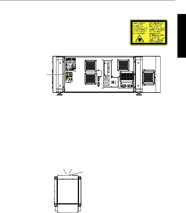
This Projector is classified as a CLASS 2 LASER PRODUCT.
This CLASS 2 LASER PRODUCT label and Caution label is located on the Rear Side surface of the projector.
Location information of the labels
LASER CAUTION |
LABEL |
WARNING
LASER RADIATION
DO NOT STARE INTO THE BEAM
CLASS 2 LASER PRODUCT
CAUTION
Do not look into the lens while in use.
Light source specifications 30 W Laser diodes ×12 Wavelength 450 - 460 nm Maximum output is 49.2 W
Beam divergence angle from lens of this unit
|
α |
Wide : α=25.9° |
Laser emission port |
Tele : α=15.4° |
|
Started Getting
5
Started Getting
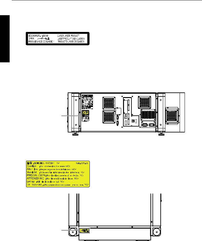
For the customers In other countries
CLASS 1 LASER PRODUCT
LASER CAUTION LABEL
WARNING
Do not look into the lens while in use.
CAUTION
Use of controls or adjustments or performance of procedures other than those specified herein may result in hazardous radiation exposure.
Location information of the labels
LASER CAUTION |
LABEL |
IEC62471-5
RG LABEL
RG LABEL
As with any bright light source, do not stare into the beam, RG2 IEC 62471-5:2015
6
ENGLISH
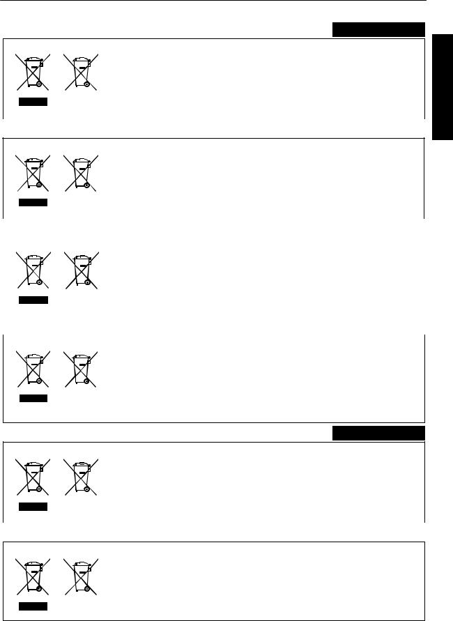
Information for Users on Disposal of Old Equipment and Batteries
|
|
|
[European Union only] |
|
|
|
|
These symbols indicate that equipment with these symbols should not be disposed |
|
|
|
|
of as general household waste. If you want to dispose of the product or battery, |
|
|
|
|
please consider the collection systems or facilities for appropriate recycling. |
|
|
|
Battery |
Notice: The sign Pb below the symbol for batteries indicates that this battery contains lead. |
|
|
|
|||
Products |
|
|
||
|
|
|
|
|
|
|
|
|
FRANÇAIS |
Informations relatives à l’élimination des appareils et des piles usagés, à l’intention des utilisateurs
|
|
|
|
[Union européenne seulement] |
||
|
|
|
|
Si ces symboles figurent sur les produits, cela signifie qu’ils ne doivent pas être jetés |
||
|
|
|
|
comme déchets ménagers. Si vous voulez jeter ce produit ou cette pile, veuillez |
||
|
|
|
|
considérer le système de collecte des déchets ou les centres de recyclage appropriés. |
||
|
|
|
Pile |
Notification: La symbole Pb en dessous du symbole des piles indique que cette |
||
|
|
|||||
Produits |
pile contient du plomb. |
|||||
|
|
|
|
|
|
|
|
|
|
|
|
ESPAÑOL / CASTELLANO |
|
|
||||||
Información para los usuarios sobre la eliminación de baterías/pilas usadas |
||||||
|
|
|
|
[Sólo Unión Europea] |
||
|
|
|
|
Estos símbolos indican que el equipo con estos símbolos no debe desecharse |
||
|
|
|
|
con la basura doméstica. Si desea desechar el producto o batería/pila, acuda |
||
|
|
|
|
a los sistemas o centros de recogida para que los reciclen debidamente. |
||
|
|
|
Baterías/pilas |
Atención: La indicación Pb debajo del símbolo de batería/pila indica que ésta |
||
|
|
|
||||
|
Productos |
|
contiene plomo. |
|||
|
|
|
|
|
|
|
|
|
|
|
|
|
DEUTSCH |
|
|
|
|
|
||
Benutzerinformationen zur Entsorgung alter Geräte und Batterien |
|
|||||
|
|
|
|
[Nur Europäische Union] |
||
|
|
|
|
Diese Symbole zeigen an, dass derartig gekennzeichnete Geräte nicht als normaler |
||
|
|
|
|
Haushaltsabfall entsorgt werden dürfen. Wenden Sie sich zur Entsorgung des |
||
|
|
|
|
Produkts oder der Batterie an die hierfür vorgesehenen Sammelstellen oder |
||
|
|
|
Batterie |
Einrichtungen, damit eine fachgerechte Wiederverwertung möglich ist. |
||
|
|
|
||||
|
|
|
Hinweis: Das Zeichen Pb unterhalb des Batteriesymbols gibt an, dass diese |
|||
Produkte |
||||||
Batterie Blei enthält.
ITALIANO
Informazioni per gli utenti sullo smaltimento delle apparecchiature e batterie obsolete
|
|
|
[Solo per l’Unione Europea] |
|
|
|
|
Questi simboli indicano che le apparecchiature a cui sono relativi non devono |
|
|
|
|
essere smaltite tra i rifiuti domestici generici. Se si desidera smaltire questo |
|
|
|
|
prodotto o questa batteria, prendere in considerazione i sistem i o le strutture di |
|
|
|
Batteria |
raccolta appropriati per il riciclaggio corretto. |
|
|
|
|||
Prodotti |
Nota: Il simbolo Pb sotto il simbolo delle batter ie indica che questa batteria contiene piombo. |
|||
|
|
|
|
|
|
|
|
|
NEDERLANDS |
Informatie voor gebruikers over het verwijderen van oude apparatuur en batterijen
|
|
|
|
[Alleen Europese Unie] |
|
|
|
|
Deze symbolen geven aan dat apparatuur met dit symbool niet mag worden |
|
|
|
|
weggegooid als algemeen huishoudelijk afval. Als u het product of de batterij wilt |
|
|
|
|
weggooien, kunt u inzamelsystemen of faciliteiten voor een geschikte recycling |
|
|
|
Batterij |
gebruiken. |
|
|
|
Opmerking: Het teken Pb onder het batterijsymbool geeft aan dat deze batterij lood bevat. |
|
|
Producten |
|
|
Started Getting
7
Started Getting
Contents |
|
Getting Started |
|
Safety Precautions .................................................. |
2 |
Names and Functions of Parts ................................ |
9 |
Front/Right, Left and Rear Side ........................... |
9 |
Right Side .......................................................... |
10 |
Connection and Installation |
|
Installation ............................................................. |
11 |
Optional Projection Lens .................................... |
11 |
Minimum Space Required ................................. |
11 |
Projector Installation Angle ................................ |
12 |
Installing the Projector and Screen ........................ |
13 |
Screen Size and Projection Distance ................. |
16 |
Connecting Video Signals of the Computer ........... |
18 |
Connection During Single-Screen Mode Display |
|
........................................................................... |
18 |
Connection During Two-Screen/Four-Screen Mode |
|
Display ............................................................... |
20 |
Network Settings |
|
Connection Using a LAN Cable ............................. |
22 |
Connection Example ......................................... |
22 |
Specifications of PC for Controlling this Projector |
|
........................................................................... |
23 |
Turning On the Main Power ................................... |
24 |
IP Address Settings ............................................... |
25 |
Assigning a static IP address ............................. |
25 |
Assigning IP Address from the DHCP Server .... |
28 |
Using the Mail Delivery Feature ............................. |
28 |
Connection Example (When DHCP Server is |
|
Used) ................................................................. |
28 |
Operation and Settings |
|
Projecting Image ................................................... |
29 |
Useful Features During Projection ..................... |
32 |
Displaying the Menu .............................................. |
33 |
User Settings Menu ............................................... |
34 |
User Settings Menu Structure ............................ |
34 |
(1) Main Menu ................................................... |
35 |
(2) Image Menu ................................................. |
37 |
(3) Setting Menu ................................................ |
38 |
(4) Convergence Menu ...................................... |
39 |
(5) Lens Menu ................................................... |
40 |
(6) Option Menu ................................................. |
41 |
Administrator Settings Menu ................................. |
42 |
Administrator Settings Menu Structure .............. |
42 |
(7) Admin.Network Menu ................................... |
43 |
(8) Admin.E-mail Menu ...................................... |
45 |
(9) Admin.Option Menu ..................................... |
47 |
(10) Admin.Signal Menu .................................... |
48 |
Others |
|
|
Troubleshooting .................................................... |
|
50 |
What to do when these messages are displayed .. |
52 |
|
Warnings Using Indicators .................................... |
53 |
|
Warning Status ...................................................... |
|
54 |
RS-232C Interface ................................................ |
|
55 |
Communication Specifications .......................... |
55 |
|
Command Format .............................................. |
|
55 |
Maintenance ......................................................... |
|
57 |
Cleaning and Replacing the Filter ...................... |
57 |
|
Routine Servicing .............................................. |
|
59 |
Specifications ........................................................ |
|
60 |
Dimensional Outline Drawing ............................ |
63 |
|
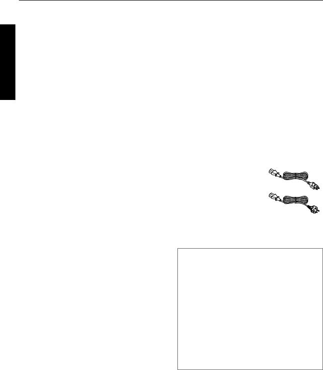
Accessories |
|
|
Power cord (for USA) |
|
|
(about. 3.3 m) |
|
|
....................................... |
1 piece |
|
Power cord (for EU) |
|
|
(about. 3.3 m) |
|
|
....................................... |
1 piece |
|
Plug Holder ................... |
1 piece |
|
0Other items include the instruction manual, warranty, and other printed materials.
Content of this manual
0Personal computers or computers are expressed as computers or PCs in this manual.
0Contents of this manual are the copyright of JVC. All rights reserved.Unauthorized reproduction and duplication of this manual, in whole or in part, without the permission of JVC is strictly prohibited.
0The names of other companies’ products that appear in this manual are the trademark or registered trademark of the respective companies.Symbols such as ™, ®, and © are omitted in this manual.
0Designs, specifications, and other details described in this manual may be modified for improvement without prior notice.
8
Names and Functions of Parts |
|
|
Front/Right, Left and Rear Side |
|
Getting |
|
|
|
|
F |
Started |
|
|
|
A |
|
Intake air |
|
|
Intake air
Intake air |
G |
Intake air
Intake air
Exhaust air
B C D E F F
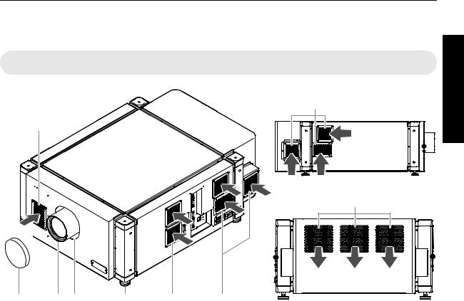
A Air Inlet/Filter
The air inlets absorb air to cool the interior of the projector. A filter is mounted inside the projector to remove dirt in the air that enters through the inlets. Clean the filter regularly. (P. 57)
0Do not block the air inlets with papers, cloth, or soft cushions. Doing so may cause heat to trap inside the projector and result in fire or malfunction.
B Lens Cap (included with the optional lens)
Fit the cap on the lens when this projector is not in use to prevent the lens from becoming dirty.
0Do not project images with the lens cap attached. The lens cap may be deformed due to the heat, or the projector may malfunction.
C Projection Lens (optional)
Zoom lens or short focal length lens is optional. (P. 60)
Remove the lens cap before projection.
D Lens Mounting Bracket
Mount the optional projection lens.
E Adjustable Feet (x4)
Adjust the feet until the projector is level. The adjustable range is 20 mm for each. (P. 12)
F Air Inlet/Filter
(Right Side: x5, Left Side: x3)
The air inlets absorb air to cool the interior of the projector. A filter is mounted inside the projector to remove dirt in the air that enters through the inlets. Clean the filter regularly. (P. 57)
G Vent Hole
Warm air exits from the hole after cooling the projector.
0Do not block the vent holes with papers, cloth, or soft cushions. Doing so may cause heat to trap inside the projector and result in fire or malfunction.
9
Getting |
Right Side |
|
|
|
|
|
H |
I |
|
|
|
|
|
|
|
|
|
|
||
Started |
|
DVI 1 |
|
|
|
|
|
|
e-shift Sync |
|
|
|
|
|
|
DVI 2 |
|
|
|
|
|
|
USB |
|
|
|
|
|
|
DVI 3 |
|
|
|
|
|
1 |
LAN |
|
|
|
|
|
|
|
OPERATE I/B |
STANDBY/ON |
|
|
|
RS-232C |
|
|
LAMP |
|
|
|
|
|
|
|
|
|
|
2 |
DVI 4 |
|
WARNING |
|
|
|
RS-232C |
|
|
|
|
|
|
JKLM |
N |
O Q |
S |
T |
|
|
|
|
|
P R |
|
|
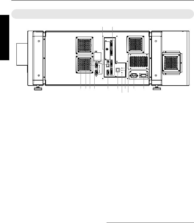
H[e-shift Sync] Terminal (DLA-VS4810 only)
This is the input terminal for e-shift sync signals.
I [DVI 1 to 4] Terminal
This is an input terminal for video signals. Connect it to the video output terminal of the computer. (P. 19, 21)
Q [LAMP] Indicator
This indicator lights up in yellow when the lifetime of the LD block exceeds 19,000 hours.
0For details, refer to “Warnings Using Indicators”P. 53.
0A message on the LD block lifespan appears when the lifetime of the LD block has exceeded 20,000 hours. (P. 52)
J [USB] Terminal
Enables control of this projector by connecting it to a computer.
K [LAN] Terminal
Enables control of this projector using a computer that is connected to the network.
L [RS-232C 1] Terminal
M [RS-232C 2] Terminal
N [RS-232C] Terminal
This is the RS-232C interface-specific terminal. This projector can be controlled by connecting it to a computer using a RS-232C cable.
O [OPERATE Z] Button
Pressing this button for one second or longer when in the standby mode (main power supply is ON) turns on the power of the projector unit. Pressing it for one second or longer when the power is ON switches the projector to the standby mode.
R [STANDBY/ON] Indicator
Lit (Red) : When in the standby mode. Lit (Green) : When power is supplied.
Blinking (Red) : When cooling down (cool down mode). (P. 31)
Blinking (Green) : When the projected image is temporarily hidden. (P. 32)
0For details, refer to “Warnings Using Indicators”P. 53.
S AC Power Input Terminal
Connect the supplied cord to this terminal.
T Main Power Supply Switch
Use this to turn ON/OFF the main power supply of the projector unit.
 MEMO
MEMO
0A stand-BY condition is indicated by the symbol B.
0Power ON condition is indicated by the symbol C.
0Power OFF condition is indicated by the symbol X.
P [WARNING] Indicator
This indicator lights up in red when abnormality occurs on this projector.
0For details, refer to “Warnings Using Indicators”P. 53.
10

Installation
Please read the following carefully when installing this unit.
Optional Projection Lens
Mount the optional projection lens (P. 60). For details on mounting the lens, please consult your authorized dealer.
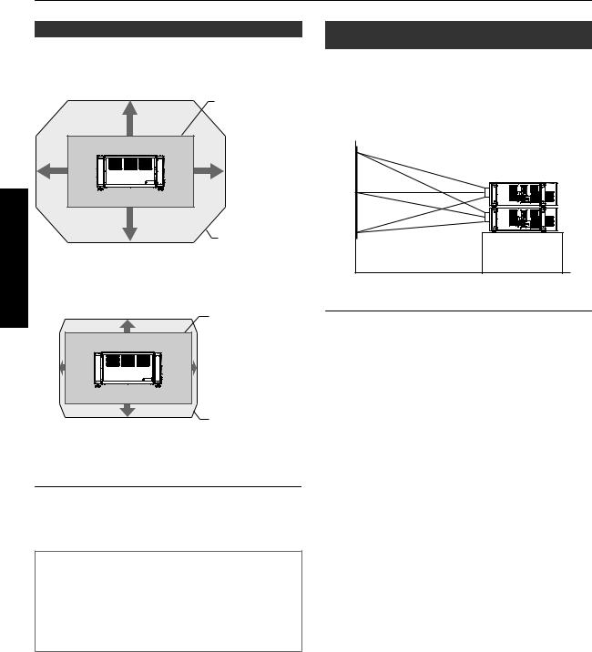
Minimum Space Required
Do not use a cover that may enclose this unit or block the air inlets/vent holes. Allow sufficient space around this unit. When this unit is enclosed in a space with dimensions as indicated below, ventilate accordingly so that the internal and external temperatures are the same.
When using one set of projector
|
300 mm |
300 mm |
600 mm |
600 mm |
600 mm |
Installation and Connection
When using two sets of projectors side by side
300 mm |
300 mm |
600 mm |
640 mm |
600 mm |
|
||
|
1300 mm |
|
When the projector is suspended
300 mm and |
above |
 MEMO
MEMO
0To prevent the projector from falling or toppling, it is recommended that the holder be fastened to the unit using bolts.
0To mount the projector to the ceiling, mount a special shelf to the ceiling, followed by installing the unit on the shelf. For safety and maintenance purposes, equipment that eases adjustment to a suitable height for maintenance is required.
 CAUTION
0Special expertise and techniques are required for mounting this unit. Be sure to ask your dealer or a specialist to perform mounting.
11
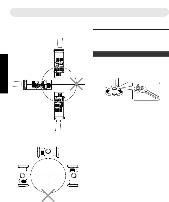
Projector Installation Angle
You can install this projector between ±90° both vertically and horizontally.
Vertical Angle
andConnection |
*Not applicable |
|
+90° |
Installation |
|
-90°
Horizontal Angle
 CAUTION
0Special expertise and techniques are required for mounting this unit. Be sure to ask your dealer or a specialist to perform mounting.
0The projector cannot be installed upside down.
Adjusting the Inclination
Adjust the horizontal angle of the projector.
Lift the projector and turn the nut of the adjustable foot with a spanner in the direction indicated by the arrow to extend or retract the foot. The adjustable range is 20 mm.
Extend Retract
+90° |
-90° |
*Not applicable
12
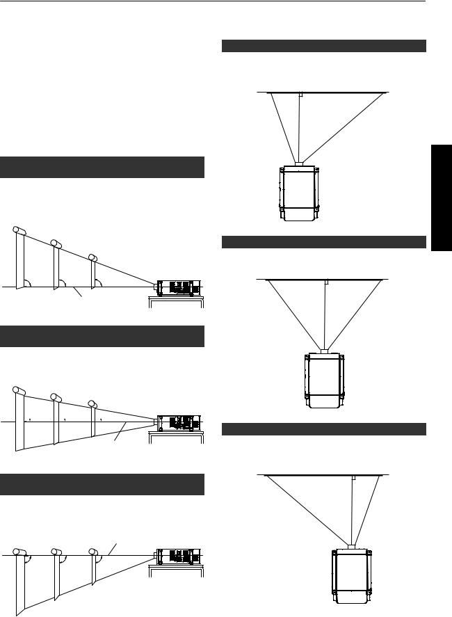
Installing the Projector and Screen
It is recommended that this projector be installed at right angle to the screen.
When a zoom lens (optional) is in use, you can make use of the lens shift feature of this projector to shift the projection screen vertically between 0% to ±50%, and horizontally between 0% to ±25%.
When a short focal length lens (optional) is in use, you can shift the projection screen position vertically between 0% to ±15%, and horizontally between 0% to ±5%.
Below are some examples on the layout when a zoom lens is used.
When shift amount in the upward direction is +50 %
Install the projector such that the lower end of the projection screen is at the same height as the center of the lens.
Screen
90° 90° 90°
Center Line of Lens
When shift amount in the upward/downward direction is 0 %
Install the projector such that the center of the projection screen is at the same height as the center of the lens.
Screen
When shift amount in the right direction is +25 %
Install the projector such that the center of the lens is aligned with the 1/4 position from the left edge of the screen.
When shift amount in the left/right direction is 0 %
Install the projector such that the center of the lens is aligned with the center of the screen.
Installation and Connection
 90°
90°  90°
90°  90°
90°
Center Line of Lens
When shift amount in the downward direction is -50 %
Install the projector such that the upper end of the projection screen is at the same height as the center of the lens.
Screen |
Center Line of Lens |
90° 90° 90°
When shift amount in the left direction is -25 %
Install the projector such that the center of the lens is aligned with the 1/4 position from the right edge of the screen.
13
Movable Range of Projected Image
GL-MS4015SZ Zoom lens
GL-MS4016SZ Zoom lens
GL-MS4021SZ Zoom lens
|
|
|
Projected Image |
|
|
|
50% |
|
|
|
25% |
|
25% |
|
Connection |
|
50% |
Movable Range |
|
|
|
|
||
and |
GL-MS4011S Short focal length lens |
|||
Installation |
||||
|
15% |
Projected Image |
||
|
5% |
|
5% |
|
|
|
15% |
Movable Range |
|
|
|
|
||
 MEMO
MEMO
0When using the lens shift feature, do not exceed the range (shift amount) as shown above. If the shift amount exceeds the range as shown, shadows will appear on the projected image.
Lens Fixation Mechanism
A screw for securing the lens mechanism is attached in the factory shipment to prevent damage of the equipment during transportation. If the lens does not move horizontally or vertically when you operate “Shift” in the “Lens” menu, this could be because the screw has not been removed. When this occurs, please consult your authorized dealer.
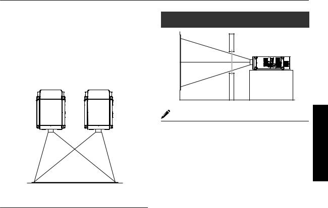
Overlaying projected images (when zoom lens is in use)
Projecting images by stacking projectors
The lens shift feature enables you to use up to three stacked projectors at the same time.
Stacking the projectors enhances the brightness level, and helps to project images that are sufficiently bright even when the venue is relatively big or bright.
 CAUTION
0When the projectors are stacked together during use, ensure that the installation site is sufficiently strong and there is proper air cooling around the projectors. Take the necessary measures to prevent the projectors from toppling or falling off so as to ensure safety during emergency situations, such as earthquakes, and to prevent accidents from occurring.
For details, please consult your authorized dealer.
14
Projecting images by arranging projectors side by side
The lens shift feature enables you to use up to two projectors that are arranged side by side.
Arranging two projectors side by side enhances the brightness level, and helps to project images that are sufficiently bright even when the venue is relatively big or bright.
When projecting images by arranging the projectors side by side, adjust the shift amount of both projectors accordingly to superimpose the images.
 CAUTION
0When using the projectors by arranging them side by side, ensure that the installation site is sufficiently strong and there is proper air cooling around the projectors.
For details, please consult your authorized dealer.
When light passes through the glass of projection booth
MEMO |
0When light passes through the glass, the quantity of light decreases. Make sure that the glass of the projection booth is not more than one piece.
0Do not use glass if possible.
0When projecting light on an inclined glass surface, adjust the glass angle as well as installation angle of this unit accordingly to prevent impact on the image due to diffuse reflection.
Installation and Connection
15

Screen Size and Projection Distance
Adjust the distance from the lens to the screen to achieve your desired screen size.
GL-MS4015SZ / GL-MS4016SZ / GL-MS4021SZ Zoom lens
|
|
Projection Screen Size |
|
|
|
Projection distance |
|
|
|
|
|
Image Width |
GL-MS4015SZ |
GL-MS4016SZ |
GL-MS4021SZ |
||||
|
|
(Diagonal Length) |
|||||||
|
|
|
Tele End |
Wide End |
Tele End |
Wide End |
Tele End |
Wide End |
|
|
|
|
|
||||||
|
|
50" (Approx. 1.27 m) |
1.10 m |
- |
- |
1.97 m |
1.58 m |
- |
- |
Connection |
|
||||||||
|
60" (Approx. 1.53 m) |
1.31 m |
- |
- |
2.37 m |
1.92 m |
- |
- |
|
|
|
||||||||
|
|
70" (Approx. 1.79 m) |
1.54 m |
- |
- |
2.78 m |
2.25 m |
- |
- |
and |
|
80" (Approx. 2.03 m) |
1.75 m |
3.19 m |
2.58 m |
3.19 m |
2.58 m |
6.38 m |
3.72 m |
|
90" (Approx. 2.29 m) |
1.97 m |
3.60 m |
2.91 m |
3.60 m |
2.91 m |
7.19 m |
4.24 m |
|
Installation |
|
||||||||
|
100" (Approx. 2.54 m) |
2.19 m |
4.01 m |
3.25 m |
4.01 m |
3.25 m |
8.01 m |
4.71 m |
|
|
|
||||||||
|
|
110" (Approx. 2.79 m) |
2.41 m |
4.42 m |
3.58 m |
4.42 m |
3.58 m |
8.82 m |
5.17 m |
|
|
120" (Approx. 3.05 m) |
2.63 m |
4.83 m |
3.91 m |
4.83 m |
3.91 m |
9.63 m |
5.64 m |
|
|
||||||||
|
|
130" (Approx. 3.30 m) |
2.85 m |
5.24 m |
4.25 m |
5.24 m |
4.25 m |
10.44 m |
6.11 m |
|
|
140" (Approx. 3.56 m) |
3.07 m |
5.65 m |
4.58 m |
5.65 m |
4.58 m |
11.25 m |
6.57 m |
|
|
150" (Approx. 3.81 m) |
3.29 m |
6.06 m |
4.91 m |
6.06 m |
4.91 m |
12.06 m |
7.04 m |
|
|
160" (Approx. 4.06 m) |
3.51 m |
6.46 m |
5.25 m |
6.46 m |
5.25 m |
12.87 m |
7.50 m |
|
|
170" (Approx. 4.32 m) |
3.73 m |
6.87 m |
5.58 m |
6.87 m |
5.58 m |
13.68 m |
7.97 m |
|
|
180" (Approx. 4.57 m) |
3.94 m |
7.28 m |
5.91 m |
- |
5.91 m |
14.49 m |
8.44 m |
|
|
190" (Approx. 4.83 m) |
4.16 m |
7.69 m |
6.24 m |
- |
6.24 m |
15.30 m |
8.90 m |
|
|
200" (Approx. 5.08 m) |
4.38 m |
8.10 m |
6.58 m |
- |
6.58 m |
16.12 m |
9.44 m |
|
|
210" (Approx. 5.33 m) |
4.60 m |
8.51 m |
6.91 m |
- |
6.91 m |
16.93 m |
9.83 m |
|
|
220" (Approx. 5.59 m) |
4.82 m |
8.92 m |
7.24 m |
- |
- |
17.74 m |
10.30 m |
|
|
230" (Approx. 5.84 m) |
5.04 m |
9.33 m |
7.58 m |
- |
- |
18.55 m |
10.77 m |
|
|
240" (Approx. 6.10 m) |
5.26 m |
9.74 m |
7.91 m |
- |
- |
19.36 m |
11.23 m |
|
|
250" (Approx. 6.35 m) |
5.48 m |
10.15 m |
8.24 m |
- |
- |
20.17 m |
11.70 m |
|
|
260" (Approx. 6.60 m) |
5.70 m |
10.55 m |
8.58 m |
- |
- |
20.98 m |
12.16 m |
|
|
270" (Approx. 6.86 m) |
5.92 m |
10.96 m |
8.91 m |
- |
- |
21.79 m |
12.63 m |
|
|
280" (Approx. 7.11 m) |
6.14 m |
11.37 m |
9.24 m |
- |
- |
22.60 m |
13.10 m |
|
|
290" (Approx. 7.37 m) |
6.36 m |
11.78 m |
9.57 m |
- |
- |
23.41 m |
13.56 m |
|
|
300" (Approx. 7.62 m) |
6.57 m |
12.19 m |
9.91 m |
- |
- |
24.23 m |
14.03 m |
 MEMO
MEMO
0The distance indicated in the table is an estimated value when an image with a resolution of 4096×2400 is projected. Please use them as reference during installation.
16

GL-MS4011S Short focal length lens
Projection Screen Size (Diagonal Length) |
Image Width |
Projection distance |
|
|
50" (Approx. 1.27 m) |
1.10 m |
1.16 m |
|
|
60" (Approx. 1.52 m) |
1.31 m |
1.41 m |
|
|
70" (Approx. 1.78 m) |
1.53 m |
1.66 m |
|
|
80" (Approx. 2.03 m) |
1.75 m |
1.91 m |
|
|
90" (Approx. 2.29 m) |
1.97 m |
2.16 m |
|
|
100" (Approx. 2.54 m) |
2.19 m |
2.41 m |
|
|
110" (Approx. 2.79 m) |
2.41 m |
2.66 m |
|
|
|
Connection |
|||
120" (Approx. 3.05 m) |
2.63 m |
2.91m |
|
|
|
|
|||
130" (Approx. 3.30 m) |
2.85 m |
3.17 m |
|
|
140" (Approx. 3.56 m) |
3.07 m |
3.42 m |
|
and |
150" (Approx. 3.81 m) |
3.29 m |
3.67 m |
|
|
|
Installation |
|||
160" (Approx. 4.06 m) |
3.51 m |
3.92 m |
|
|
|
|
|||
170" (Approx. 4.32 m) |
3.73 m |
4.17 m |
|
|
180" (Approx. 4.57 m) |
3.94 m |
4.42 m |
|
|
|
|
|||
190" (Approx. 4.83 m) |
4.16 m |
4.67 m |
|
|
200" (Approx. 5.08 m) |
4.38 m |
4.92 m |
|
|
210" (Approx. 5.33 m) |
4.60 m |
5.17 m |
|
|
220" (Approx. 5.59 m) |
4.82 m |
5.43 m |
|
|
230" (Approx. 5.84 m) |
5.04 m |
5.68 m |
|
|
240" (Approx. 6.10 m) |
5.26 m |
5.93 m |
|
|
250" (Approx. 6.35 m) |
5.48 m |
6.18 m |
|
|
 MEMO
MEMO
0The distance indicated in the table is an estimated value when an image with a resolution of 4096×2400 is projected. Please use them as reference during installation.
17

Connecting Video Signals of the Computer
Connection During Single-Screen Mode Display
The single-screen mode displays signals (up to four signals) from a computer as a single video image. To select to the single-screen mode, set “Display Mode” in the “Setting” menu to “Single”. (P. 38)
Possible Input Signals and Projected Image
|
|
|
Computer |
|
Projector |
|
|
|
|
Connection |
|
|
|
|
|
Displayed |
|||
|
|
2ch |
Dual |
DVI 1, DVI 3 |
2 Stripes |
2048×2400 |
|||
|
|
Resolution |
Channel |
Link Status |
Terminal for |
Output Status |
Projector Image |
||
|
|
Connection |
|
|
|||||
and |
|
|
|
|
|
|
|
4096×2400 |
|
|
4096×2400 |
|
|
|
Cross |
2048×1200 |
|||
|
4ch |
Single |
DVI 1 to DVI 4 |
* (8192×4800) |
|||||
4 Stripes |
1024×2400 |
||||||||
Installation |
|
|
|
|
|
|
|||
|
4096×2160 |
4ch |
Single |
DVI 1 to DVI 4 |
Cross |
2040×1080 |
* (8192×4320) |
||
|
|
|
2ch |
Dual |
DVI 1, DVI 3 |
2 Stripes |
2048×2160 |
4096×2160 |
|
|
|
|
|
|
|
|
|
||
|
|
|
|
|
|
4 Stripes |
1024×2160 |
|
|
|
|
|
|
|
|
|
|||
|
|
|
2ch |
Dual |
DVI 1, DVI 3 |
2 Stripes |
1920×2400 |
3840×2400 |
|
|
|
3840×2400 |
|
|
|
Cross |
1920×1200 |
||
|
|
4ch |
Single |
DVI 1 to DVI 4 |
* (7680×4800) |
||||
|
|
|
4 Stripes |
960×2400 |
|||||
|
|
|
|
|
|
|
|||
|
|
|
2ch |
Dual |
DVI 1, DVI 3 |
2 Stripes |
1920×2160 |
3840×2160 |
|
|
|
3840×2160 |
|
|
|
Cross |
1920×1080 |
||
|
|
4ch |
Single |
DVI 1 to DVI 4 |
* (7680×4320) |
||||
|
|
|
4 Stripes |
960×2160 |
|||||
|
|
|
|
|
|
|
|||
|
|
2048×1200 |
1ch |
Single |
DVI 1 |
Normal |
2048×1200 |
4096×2400 |
|
|
|
2048×1080 |
1ch |
Single |
DVI 1 |
Normal |
2048×1080 |
4096×2160 |
|
|
|
1920×1200 |
1ch |
Single |
DVI 1 |
Normal |
1920×1200 |
3840×2400 |
|
|
|
1920×1080 |
1ch |
Single |
DVI 1 |
Normal |
1920×1080 |
3840×2160 |
|
|
|
1600×1200 |
1ch |
Single |
DVI 1 |
Normal |
1600×1200 |
3200×2400 |
|
|
|
1280×1024 |
1ch |
Single |
DVI 1 |
Normal |
1280×1024 |
2560×2048 |
|
|
|
1024×768 |
1ch |
Single |
DVI 1 |
Normal |
1024×768 |
2048×1536 |
|
|
|
800×600 |
1ch |
Single |
DVI 1 |
Normal |
800×600 |
1600×1200 |
|
|
|
640×480 |
1ch |
Single |
DVI 1 |
Normal |
640×480 |
1280×960 |
|
* (DLA-VS4810) An 8K image is displayed when e-shift sync signal is input.
 MEMO
MEMO
0This projector converts the frame rate to 60 Hz regardless of the synchronizing signal frequency at the computer’s end.
0If the resolution of the PC is 2048×1200 or lower, images are displayed upon doubling the number of the vertical and horizontal pixels.
18
|
Normal |
|
|
|
2 Stripes |
|||
|
|
|
|
|
|
|
|
|
|
DVI 1 |
DVI 1 |
|
DVI 3 |
||||
|
|
|
|
|
|
|
|
|
|
|
|
|
|
|
|
|
|
|
|
4 Stripes |
|
|
|
|
|
Cross |
|||
|
|
|
|
|
|
|
|
|
|
|
|
|
DVI 1 |
DVI 2 |
DVI 3 |
DVI 4 |
|
|
DVI 1 |
|
DVI 2 |
|
|
|
|
|
|
|
|
|
|
|
|
|
|
|
|
|
|
|
|
|
|
DVI 3 |
|
DVI 4 |
|
|
|
|
|
|
|
|
|
|
|
|
|
|
|
|
|
|
|
|
|
|
|
|
|
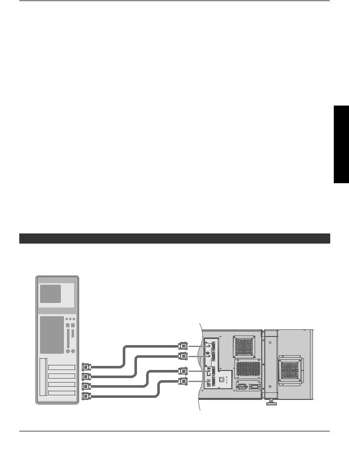
Connection During Single-Screen Mode Display
Below is the connection example for four-channel signals from the computer.
For two-channel signals from the computer, connect to the [DVI 1] and [DVI 3] terminals of this projector.
Desktop Computer
|
DVI-D Cable |
|
(Sold Separately) |
To DVI |
DVI 1 |
e-shift Sync |
|
Terminal |
DVI 2 |
|
USB |
|
DVI 3 |
|
LAN |
|
OPERATE I/B STANDBY/ON |
|
S-232C |
|
LAMP |
|
DVI 4 WARNING |
|
RS-232C |
 MEMO
MEMO
0Depending on your DVI-D cable, the signal may attenuate and the image become unstable.
0Use of DVI-D cables compliant with the DDWG standard is recommended.
Installation and Connection
19
Connection During Two-Screen/Four-Screen Mode Display
The two-screen/four-screen mode enables simultaneous display of signals from two or four computers.
To select the two-screen mode, set “Display Mode” in the “Setting” menu to “Double”. To select the four-screen mode, set “Display Mode” to “Cross”. (P. 38)
Possible Input Signals and Projected Image
|
|
|
Computer |
|
|
Output Status |
|
|
|
Resolution |
Channel |
Link Status |
|
||
|
|
|
|
|
|||
Connection |
|
|
|
|
|||
|
2048×1200 |
1ch |
Single |
Normal |
|
2048×1200 |
|
|
|
|
|||||
|
|
2048×1080 |
1ch |
Single |
Normal |
|
2048×1080 |
and |
|
1920×1200 |
1ch |
Single |
Normal |
|
1920×1200 |
|
1920×1080 |
1ch |
Single |
Normal |
|
1920×1080 |
|
Installation |
|
|
|
|
|
|
|
|
1024×768 |
1ch |
Single |
Normal |
|
1024×768 |
|
|
|
1600×1200 |
1ch |
Single |
Normal |
|
1600×1200 |
|
|
1280×1024 |
1ch |
Single |
Normal |
|
1280×1024 |
|
|
|
|
|
|
|
|
|
|
800×600 |
1ch |
Single |
Normal |
|
800×600 |
|
|
640×480 |
1ch |
Single |
Normal |
|
640×480 |
 MEMO
MEMO
0This projector converts the frame rate to 60 Hz regardless of the synchronizing signal frequency at the computer’s end.
0The respective signals are displayed at the center of the split screen.
0When in the two-screen mode, the screen appears blue (or black depending on the setting) when there is no input.
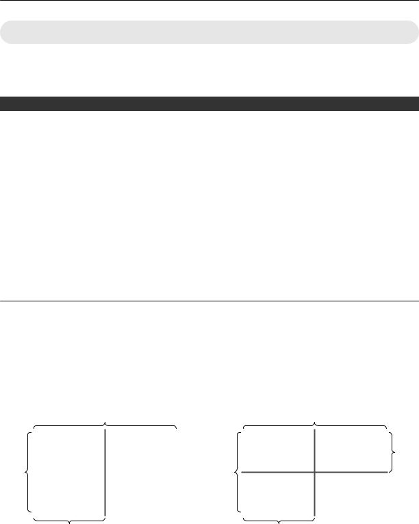
Two-Screen Mode |
|
|
Four-Screen Mode |
|
|
|
|
|
|
|
|
|||||||
(Example) DVI 1: 1920×1080, |
|
|
(Example) DVI 1: 2048×1200, DVI 2: 1920×1080, |
|
||||||||||||||
|
|
DVI 3: 1920×1080 |
|
|
|
DVI 3: 1024×768, DVI 4: 1600×1200 |
|
|||||||||||
|
4096 |
|
|
|
|
|
|
4096 |
|
|
|
|
|
|||||
|
|
|
|
|
|
|
|
|
|
|
|
|
|
|
|
|
|
1200 |
|
|
|
|
|
|
|
|
|
|
|
|
|
|
|
|
|
||
2400 |
|
|
|
|
|
|
|
|
DVI 1 |
|
|
|
DVI 2 |
|
|
|||
|
DVI 1 |
|
|
DVI 3 |
|
2400 |
||||||||||||
|
|
|
|
|
|
|
|
|
|
|
|
|
|
|
||||
|
|
|
|
|
|
|
|
|
|
|
|
|
|
|
||||
|
|
|
|
|
|
|
|
|
|
|
|
|
|
|
||||
|
|
|
|
|
|
|
|
|
DVI 3 |
|
|
|
|
DVI 4 |
|
|
|
|
|
|
|
|
|
|
|
|
|||||||||||
|
|
|
|
|
|
|
|
|
|
|
|
|
|
|
|
|
|
|
|
|
|
|
|
|
|
|
|
|
|
|
|
|
|
|
|
|
|
|
2048 |
|
|
|
|
2048 |
|
|
|
|
|
|
|
|
|
|||
. |
|
|
|
|
|
|
. |
|
|
|
|
|
|
|
|
|
|
|
20
Loading...