


 Loading...
SERVICE MANUAL
HDD&DVD VIDEO RECORDER
DR-MH300BE2, DR-MH300BEK2, DR-MH300SE2, DR-MH300SEK2, DR-ED400SE2
Only ver.E,EK |
|
|
|
|
|
Only ver.EK |
|
|
|
|
|
|
|
|
|
|
Area Suffix |
||||
|
|
|
|
|
|
|
|
|
|
|
|
|
|
|
|
|
|
|
|
E |
Continental Europe |
|
|
|
|
|
|
|
|
|
|
|
|
|
|
|
|
|
|
|
|
||
|
|
|
|
|
|
TM |
Northern Europe |
||||||||||||||
|
|
|
|
|
|
|
|
|
|
|
|
|
|
|
|
|
|
|
|
|
|
|
|
|
|
|
|
|
|
|
|
|
|
|
|
|
|
|
|
|
|
EK ------------------------ |
U.K. |
|
|
|
|
|
|
|
|
|
|
|
|
|
|
|
|
|
|
|
|
|
|
|
|
|
|
|
|
|
|
|
|
|
|
|
Only ver.E |
|
|
|
|||||
|
|
|
|
|
|
|
|
|
|
|
|
|
|
|
|
|
|
|
|
TM |
|
|
|
|
|
|
|
|
|
|
|
|
|
|
|
|
|
|
|
|
|
|
|
|
|
|
|
|
|
|
|
|
|
|
|
|
|
|
|
|
|
|
|
|
|
|
|
|
|
|
|
|
|
|
|
|
|
|
|
|
|
|
|
|
|
|
|
|
|
|
|
|
|
|
|
|
|
|
|
|
|
|
|
|
|
|
|
|
|
|
|
|
|
|
|
|
|
|
|
|
|
|
|
|
|
|
|
|
|
|
|
|
|
|
|
|
|
|
|
|
|
|
|
|
|
|
|
|
|
|
|
|
|
PR
|
|
|
RAM/RW |
|
STANDBY/ON |
HDD |
DVD |
NAVIGATION GUIDE |
ENTER |
PUSH-OPEN
PR
DR-MH300BE2, DR-MH300BEK2, DR-MH300SE2,
DR-MH300SEK2, DR-ED400SE2 [D5HR10]
Since the whole mechanism assembly unit is replaced, the DVD recorder mechanism of this unit need not be adjusted.
This model is a model to whom the DVD drive unit and some parts are changed based on DR-MH300B,DR-MH300S,DR-ED400S.
Please see page 3 about details and the distinction method.
For details other than those described in this manual, please refer to the DR-MH300B,DR-MH300S,DR-ED400S service manual (Issue No.YD089 2005/12).
TABLE OF CONTENTS
1 PRECAUTION. . . . . . . . . . . . . . . . . . . . . . . . . . . . . . . . . . . . . . . . . . . . . . . . . . . . . . . . . . . . . . . . . . . . . . . . . 1-4 2 SPECIFIC SERVICE INSTRUCTIONS . . . . . . . . . . . . . . . . . . . . . . . . . . . . . . . . . . . . . . . . . . . . . . . . . . . . . . 1-4 3 DISASSEMBLY . . . . . . . . . . . . . . . . . . . . . . . . . . . . . . . . . . . . . . . . . . . . . . . . . . . . . . . . . . . . . . . . . . . . . . . 1-5 4 ADJUSTMENT . . . . . . . . . . . . . . . . . . . . . . . . . . . . . . . . . . . . . . . . . . . . . . . . . . . . . . . . . . . . . . . . . . . . . . . 1-11 5 TROUBLESHOOTING . . . . . . . . . . . . . . . . . . . . . . . . . . . . . . . . . . . . . . . . . . . . . . . . . . . . . . . . . . . . . . . . . 1-12
COPYRIGHT © 2006 Victor Company of Japan, Limited
No.YD089B
2006/2
SPECIFICATION
|
DR-MH300BE2,DR-MH300SE2,DR-ED400SE2 |
DR-MH300BEK2,DR-MH300SEK2 |
|
|
|
GENERAL |
|
|
Power requirement |
AC 220 V - 240 V~, 50 Hz/60 Hz |
|
Power consumption |
Power on : 36 W |
|
|
Power off : 6.4 W |
|
Temperature |
Operating : 5°C to 35°C |
|
|
Storage : -20°C to 60°C |
|
Operating position |
Horizontal only |
|
Dimensions (W × H × D) |
435 mm × 70 mm × 300 mm |
|
Weight |
4.6 kg |
|
VIDEO/AUDIO (DVD Deck) |
|
|
Recordable disc |
DVD-RAM 12 cm (4.7 GB/9.4 GB*1),DVD-RAM 8 cm (1.4 GB/2.8 GB*2),DVD-R 12 cm (4.7 GB),DVD-R 8 cm (1.4 GB),DVD- |
|
|
RW 12 cm (4.7 GB),DVD-RW 8 cm (1.4 GB) |
|
|
*1 9.4 GB double-sided discs |
|
|
*2 2.8 GB double-sided discs |
|
Recording format |
DVD-RAM : DVD Video Recording format |
|
|
DVD-R : DVD Video format, DVD Video Recording format |
|
|
DVD-RW : DVD Video format, DVD Video Recording format |
|
Recording time |
Maximum 8 hours (with 4.7 GB disc) |
|
|
(XP) : Approx. 1 hour, (SP) : Approx. 2 hours, (LP) : Approx. 4 hours, (EP) : Approx. 6 hours, (FR) : Approx. 1 hour - 8 hours |
|
Audio recording system |
Dolby Digital (2 ch) |
|
|
Linear PCM (XP mode only) |
|
Video recording compression system |
MPEG2 (CBR/VBR) |
|
VIDEO/AUDIO (HDD Deck) |
|
|
Capacity |
160 GB |
|
Recording time |
(DV) : Approx. 11 hours,(XP) : Approx. 34 hours,(SP) : Approx. 69 hours,(LP) : Approx. 138 hours, |
|
|
(EP) : Approx. 209 hours,(FR480) : Approx. 300 hours |
|
Audio recording system |
Dolby Digital (2 ch) |
|
|
Linear PCM (XP mode only) |
|
Video recording compression system |
MPEG2 (VBR) |
|
Input/Output |
|
|
21-pin SCART connectors |
IN/OUT X 1, IN/DECODER X 1 |
|
S-video input |
Y:1.0 Vp-p,75 ohms |
|
|
C : 0.3Vp-p, 75 ohms |
|
Video input |
1.0 Vp-p, 75 ohms (pin jack) |
|
Audio input |
2 Vrms (pin jack) |
|
i.Link |
4-pin for DV Input/Output |
|
Component video output |
Y : 1.0 Vp-p, 75 ohms |
|
|
PB/PR: 0.7 Vp-p, 75 ohms |
|
|
Corresponding to copy protection |
|
HDMI output |
19-pin, Corresponding to HDCP |
|
|
Video : 576i/576p/1080i/720p |
|
|
Audio : 2 ch PCM/Bitstream |
|
Digital audio output |
Coaxial |
|
|
Corresponding to Dolby Digital and DTS Digital Surround, |
|
|
Bit stream |
|
|
Selectable in digital audio output setting menu |
|
G-LINK |
3.5 mm Jack |
|
TUNER/TIMER |
|
|
Tuning system |
Frequency synthesised tuner |
|
Signal system |
PAL/SECAM colour signal, 625 lines/50 fields |
PAL colour signal,625 lines/50 fields |
TV channel storage capacity |
99 positions (+AUX position) |
|
Channel coverage(SECAM-L) |
- |
- |
Channel coverage(PAL) |
VHF : 47 MHz - 89 MHz/ |
VHF : 44.5MHz - 143MHz/ |
|
104 MHz - 300 MHz/ |
143MHz - 470MHz/ |
|
302 MHz - 470 MHz |
UHF : 470MHz - 862MHz |
|
UHF : 470MHz - 862MHz |
|
Memory backup time |
Approx. 10 minutes. |
|
E.& O.E. Design and specifications subject to change without notice.
•Manufactured under license from Dolby Laboratories. “Dolby” and the double-D symbol are trademarks of Dolby Laboratories.
•“DTS” and “DTS Digital Out” are trademarks of Digital Theater Systems, Inc.
•This product incorporates copyright protection technology that is protected by U.S. patents and other intellectual property rights. Use of this copyright protection technology must be authorized by Macrovision. Reverse engineering or disassembly is prohibited.
•GUIDE Plus+, SHOWVIEW,VIDEO Plus+, G-LINK are (1) registered trademarks or trademarks of, (2) manufactured under license from and (3) subject of various international patents and patent applications owned by, or licensed to, Gemstar-TV Guide International, Inc. and/or its related affiliates.
•GEMSTAR-TV GUIDE INTERNATIONAL, INC. AND/OR ITS RELATED AFFILIATES ARE NOT IN ANY WAY LIABLE FOR THE ACCURACY OF THE PROGRAM SCHEDULE INFORMATION PROVIDED BY THE GUIDE PLUS+ SYSTEM. IN NO EVENT SHALL GEMSTAR-TV GUIDE INTERNATIONAL, INC. AND /OR ITS RELATED AFFILIATES BE LIABLE FOR ANY AMOUNTS REPRESENTING LOSS OF PROFITS, LOSS OF BUSINESS, OR INDIRECT, SPECIAL, OR CONSEQUENTIAL DAMAGES IN CONNECTION WITH THE PROVISION OR USE OF ANY INFORMATION, EQUIPMENT, OR SERVICES RELATING TO THE GUIDE PLUS+ SYSTEM.
•i-LINK is a trademark of Sony Corp .
•HDMI is a trademark of HDMI Licensing, LLC .
1-2 (No.YD089B)
About this service manual
This model is a model to whom the DVD drive unit and some parts are changed based on DR-MH300BE,DR-MH300BEK,DR-MH300SE,DR-MH300SEK,DR-ED400SE.
Since the way of recognizing is explained below, in the case of DR-MH300BE2, DR-MH300BEK2,DR-MH300SE2,DR-MH300SEK2,DR-ED400SE2, please use this manual. In the case of DR-MH300BE,DR-MH300BEK,DR-MH300SE,DR-MH300SEK,DR-ED400SE, please refer to another service manual (No.YD089 2006/2).
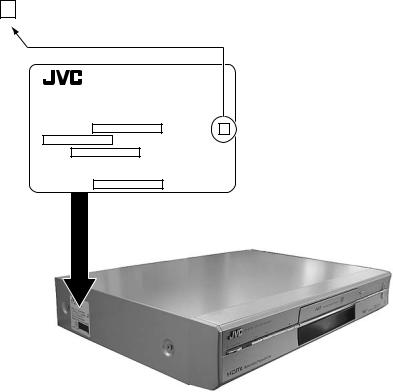
HOW TO IDENTIFY MODELS
How to recognize from the appearance of the model concerned is written below.
Please distinguish from several contents currently printed on the rating label of the left side on main body.
BLANK : DR-MH300BE,DR-MH300BEK,DR-MH300SE,DR-MH300SEK,DR-ED400SE
2 : DR-MH300BE2,DR-MH300BEK2,DR-MH300SE2,DR-MH300SEK2,DR-ED400SE2
DVD VIDEO RECORDER
MODEL NO. |
2 |
S, NO.
MADE IN
The surface of a top cover
(No.YD089B)1-3
SECTION 1
PRECAUTION
Please refer to "DR-MH300BE, DR-MH300BEK,DR-MH300SE,DR-MH300SEF,DR- MH300SEK, DR-MH300SER,DR-ED400SE (issue number : YD089)" about this section.
SECTION 2
SPECIFIC SERVICE INSTRUCTIONS
This service manual does not describe SPECIFIC SERVICE INSTRUCTIONS.
1-4 (No.YD089B)
SECTION 3
DISASSEMBLY
3.1Main body section
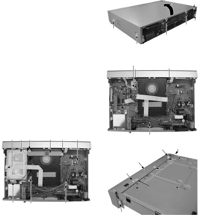
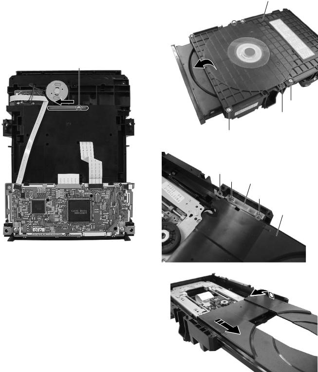
3.1.1 Remove the top cover (See figure 1)
(1)Remove the four screws A attaching the top cover on both sides of the main body.
(2)Remove the five screws B attaching the top cover on the back of the main body.
(3)Raise the both sides and lower part of the rear of the top cover, with opening them slightly in an outward direction. And the top cover will be removed.
A x 2
A x 2 
3.1.2 Remove the front panel assembly and HDD (See figure 2, figure 3, figure 4)
•Prior to performing the following procedure, remove the top cover.
•There is no need to remove the drive unit.
(1)Remove the five screws C attaching the HDD and bracket.
(2)Disconnect the card wire from connector CN2201 on the
digital board.
(3) Disconnect the socket wire from connector CN5304 on the main board.
(4)Disconnect the card wire from connector on the HDD.
(5)Disconnect the card wire from connector CN4001 on the main board.
(6)Disconnect the card wires from connector CN7002, CN7003 on the display board.
(7)Remove the two screws D attaching the front panel assembly.
(8)Hooks a and b are removed respectively, and the front panel assembly is removed.
B
TOP COVER
B
B
B
B
Fig.1
CN7003
CN2201 HDD C |
Bracket C |
Main board |
Main board |
|
Fig.3 |
||||
|
|
|
D |
Hook a |
C 

Front panel assembly
D
C
 Hook b
Connector |
C |
CN5304 |
Fig.2
Hook a
Fig.4
(No.YD089B)1-5
3.1.3 Remove the drive unit (See figure 5)
•Prior to performing the following procedure, remove the top cover.
•There is no need to remove the front panel assembly.
(1)Disconnect the socket wire from connector CN5302 on the main board.
(2)Disconnect the card wire from connector CN2201 on the digital board.
(3)Remove the five screws E attaching the drive unit and bracket.
E |
|
|
Bracket |
||||
Drive unit |
|
E CN5302 |
|||||
|
|
|
|
|
|
|
|
|
|
|
|
|
|
|
|
|
|
|
|
|
|
|
|
|
|
|
|
|
|
|
|
|
|
|
|
|
|
|
|
|
|
|
|
|
|
|
|
|
|
|
|
|
CN2201 |
E Main board |
E |
||||
|
|
|
Fig.5 |
|
|
|
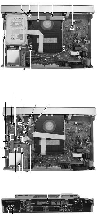
3.1.4 Remove the HDMI board and digital board (See figure 6, figure 7)
• Prior to performing the following procedure, remove the top cover and HDD.
(1) Disconnect the socket wire from connector CN2404 on the HDMI board.
(2)Remove the three screws F attaching the HDMI board.
(3)Remove the two screws G (G1, G2) attaching the HDMI board from rear side.
(4)Disconnect the connector from CN2401 on the HDMI board
from digital board.
(5) Disconnect the card wire from connector CN1103 on the digital board.
(6) Disconnect the socket wire from connector CN1101, CN1102, CN1801 on the digital board.
(7) Remove the four screws H attaching the digital board.
CN2404 F H
HDMI board
Fig.6
Rear panel
G1G2
Torque
Please note tightening too much.
G1 --- 0.784 N-m +- 0.078N-m ( 8.0 kgf-cm +- 0.8 kgf-cm )
G2 --- 0.25 N-m ~ 0.35N-m ( 2.6 kgf-cm ~ 3.6 kgf-cm )
Fig.7
1-6 (No.YD089B)
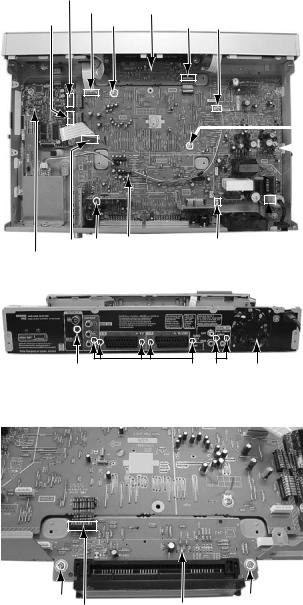
3.1.5 Remove the main board (See figure 8, figure 9)
•Prior to performing the following procedure, remove the top cover, drive unit, HDD.
(1)Disconnect the card wire from connector CN4103, CN4001 on the main board.
(2)Disconnect the socket wire from connector CN1101, CN1102, CN7001 on the digital board and display board.
(3)Disconnect the socket wire from connector CN3004, CN5303 on the main board.
(4)Disconnect the power cord from connector CN5001 on the main board.
(5)Remove the six screws I attaching the main board.
(6)Remove the seven screws J attaching the rear panel with main board.
(7)Remove the one screw K attaching the tuner.
3.1.6 Remove the display board (See figure 10)
•Prior to performing the following procedure, remove the top cover, drive unit, HDD, front panel assembly.
(1)Disconnect the socket wire from connector CN7001 on the display board.
(2)Remove the two screws L attaching the display board.
CN1101 |
|
|
|
CN4001 |
Display board |
CN1102 |
I |
CN7001 CN3004 |
 I
I
 I
I

 I
I

 I
I
CN4103 I Main board CN5303 CN5001 Digital board
Fig.8
K |
J J |
Rear panel |
Fig.9
L L
CN7001 Display board
Fig.10
(No.YD089B)1-7
3.2DVD Drive unit section
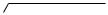
3.2.1 Remove the top cover and tray (See figure 1, figure2, figure3, figure4) |
|
|||||
(1) |
The part a on the reverse side of a DVD drive unit is made |
|
Hook b A |
Top cover |
||
|
to slide in the direction of an arrow. (A tray ejects a few.) |
|
||||
(2) |
Remove the four screws A attaching the top cover. |
A |
|
|
|
|
(3) |
Hooks b are removed, and the top cover is removed. |
|
|
|
||
(4) |
The tray is drawn out forward. |
|
|
|
|
|
|
|
|
|
|
||
(5) |
Remove the two screws B attaching the shaft guide, and |
|
|
|
|
|
|
hook c is removed. |
|
|
|
|
|
|
|
|
|
|
|
|
(6)It draws it out while lifting the tray in the direction of the arrow.
Part a
A
Hook b
A
Fig.2
Hook c
B Shaft guide
B
Tray
Fig.1
Fig.3
Fig.4
1-8 (No.YD089B)

3.2.2 Reassembly the tray (See figure 5) |
Shaft guide |
|
(1) |
The slide cam is done in the slide in the direction of the ar- |
|
|
row. |
|
(2) |
The shaft guide is done in the slide in the direction in the |
|
|
back. |
|
(3) |
The left side of the tray is inserted in the rail of the loading |
|
|
base, and the shaft guide is built in. |
|
(4) |
Please push the tray, and confirm whether the tray is nor- |
|
|
mally good to the close position at the slide by manual. |
|
|
|
Slide cam |
|
|
|
|
Fig.5 |
|
|
3.2.3 Remove the traverse mechanism assembly (See figure 6, figure 7) |
|
|
||
• Prior to performing the following procedure, remove the top |
CN105 |
Servo control board |
CN103 |
|
cover, tray. |
||||
|
|
|
||
(1)Disconnect the FFC wire from connector on the pick-up unit.
ATTENTION:
The laser diode of "pick-up" might be destroyed by static electricity. Please work after installing the wristband. In addition, please do not touch in each part, the terminal, and the laser diode terminal on the substrate of the pickup unit. Never
(2)Disconnect the FFC wire from connector CN103, CN104 on the servo control board.
(3)Remove the four screws C attaching the traverse mechanism assembly.
C Traverse mechanism assembly
Hook d |
CN102 CN104 |
Hook d |
D |
|
D |
|
Fig.7 |
|
C
 C
C
Connector Pick-up unit
Fig.6
(No.YD089B)1-9
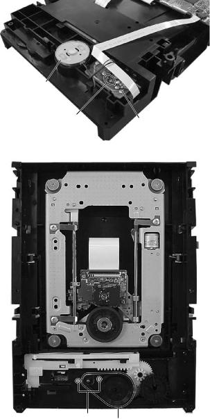
3.2.4 Remove the servo control board (See figure 7)
(1)Disconnect the FFC wire from connector CN102, CN103, CN104, CN105 on the servo control board.
(2)Remove the two screws D attaching the servo control board.
(3)Hooks d is removed, and the servo control board is removed.
3.2.5 Remove the loading motor (See figure 8, figure 9)
•Prior to performing the following procedure, remove the top cover, tray.
(1)Remove the solder part e soldered on the switch board.
(2)A belt is removed.
(3)Remove the two screws E attaching the loading motor.
Loading
motor
Part e |
Switch board |
Fig.8
E Belt
Fig.9
1-10 (No.YD089B)
SECTION 4
ADJUSTMENT
4.1Timer clock adjustment (for only ver.E)
If an error comes to arise for a clock, the following procedure will adjust.
Signal |
(A1) |
No signal |
|
|
|
Mode |
(B) |
EE |
|
|
|
Equipment |
(C) |
Frequency counter |
|
|
|
Measuring point |
(D1) |
IC3001 pin 29 |
|
(D2) |
IC3001 pin 83 |
|
(D3) |
C3021 + and - |
Adjustment part |
(F) |
C3033 (TIMER CLOCK) |
|
|
|
Specified value |
(G1) |
1024.008 ±0.001 Hz |
|
|
(976.5549 ±0.0010 usec) |
|
|
|
(1)Connect the frequency counter to the measuring point (D1).
(2)Connect the short wire between the short point (D2) and Vcc (5V).
(3)Short the leads of capacitor (D3) once in order to reset the microprocessor of the system controller.
(4)Disconnect the short wire between the short point (D2) and Vcc then connect it again.
(5)Adjust the Adjustment part (F) so that the output frequency becomes the specified value (G).
(No.YD089B)1-11

SECTION 5
TROUBLESHOOTING
5.1JIG Mode
Please refer to "DR-MH300BE, DR-MH300BEK,DR-MH300SE,DR-MH300SEF,DR-MH300SEK, DR-MH300SER,DR-ED400SE (issue number : YD089)" about this section.
5.2Displaying SYSTEM INFO
Please refer to "DR-MH300BE, DR-MH300BEK,DR-MH300SE,DR-MH300SEF,DR-MH300SEK, DR-MH300SER,DR-ED400SE (issue number : YD089)" about this section.
5.3Updating the firmware of the main body
Please refer to "DR-MH300BE, DR-MH300BEK,DR-MH300SE,DR-MH300SEF,DR-MH300SEK, DR-MH300SER,DR-ED400SE (issue number : YD089)" about this section.
5.4Updating the firmware of the drive unit
Please refer to "DR-MH300BE, DR-MH300BEK,DR-MH300SE,DR-MH300SEF,DR-MH300SEK, DR-MH300SER,DR-ED400SE (issue number : YD089)" about this section.
5.5Taking out a disc
< Method 1 >
There is a forced tray eject mode with electrical operation.
(1)Right after plugging in the power code (while “PLEASE” and “WAIT” blink alternately and it is displayed), keep pressing the OPEN/CLOSE button of the main body.
(2)Remove the disc as the tray is ejected in a short while.
(3)The tray closes automatically at about five seconds.
<Method 2 >
When < Method 1 > can not remove the disc, the tray can be ejected mechanically without turning the power on.
(1)The DVD drive unit is detached from the main body.
(2)The part a on the reverse side of a drive unit is made to slide in the direction of an arrow with a screw driver etc.
(3)As the tray ejects a little, pull out the tray manually.
Part a
1-12 (No.YD089B)
Loading...