


 Loading...
D-ILA PROJECTOR
DLA-VS2400ZG DLA-VS2400G
For Customer use :
Enter below the serial No. which is located on the back of the cabinet. Retain this information for future reference.
Model No. DLA-VS2400ZG
DLA-VS2400G
Serial No.
INSTRUCTIONS
up Set Started Getting
Operate
Others Troubleshooting Maintenance Adjust/Set
LCT2727-002A
Safety Precautions
Getting |
|
IMPORTANT INFORMATION |
|
|
|
Started |
|
This product has a High Intensity |
|
mercury. |
|
|
|
Dis-charge (HID) lamp that contains |
|
|
Disposal of these materials may be |
|
|
|
|
|
regulated in your community due to |
|
|
environmental considerations. For |
|
|
disposal or recycling information, |
|
|
please contact your local authorities or |
|
|
for USA, the Electronic Industries |
|
|
Alliance: http://www.eiae.org. |
|
|
|
|
|
WARNING: |
|
|
TO PREVENT FIRE OR SHOCK HAZARDS, DO |
|
|
NOT EXPOSE THIS APPLIANCE TO RAIN OR |
|
|
MOISTURE. |
|
|
|
|
|
WARNING: |
|
|
THIS APPARATUS MUST BE EARTHED. |
|
|
|
|
|
CAUTION: |
|
|
To reduce the risk of electric shock, do not remove |
|
|
cover. Refer servicing to qualified service personnel. |
|
|
|
|
|
This projector is equipped with a 3-blade grounding |
|
|
type plug to satisfy FCC rule. If you are unable to |
|
|
insert the plug into the outlet, contact your electrician. |
|
|
|
|
|
MACHINE NOISE INFORMATION |
|
|
(Germany only) |
|
|
Changes Machine Noise Information Ordinance 3. |
|
|
GSGV, January 18, 1991: The sound pressure level |
|
|
at the operator position is equal or less than 40 dB |
|
|
(A) according to ISO 7779. |
|
|
|
|
|
For the customers in Taiwan only |
|
|
|
WARNING
This is a Class A product. In a domestic environment this product may cause radio interference in which case the user may be required to take adequate measures.
In case where the strong electromagnetic waves or magnetism are near the signal cable, the picture will contain noise. In such cases, please keep the cable away from the sources of the disturbance.
About the installation place
Do not install the projector in a place that cannot support its weight securely.
If the installation place is not sturdy enough, the projector could fall or overturn, possibly causing personal injury.
FCC INFORMATION (U.S.A. only) CAUTION:
Changes or modification not approved by JVC could void the user’s authority to operate the equipment.
NOTE:
This equipment has been tested and found to comply with the limits for a Class A digital device, pursuant to Part 15 of the FCC Rules. These limits are designed to provide reasonable protection against harmful interference when the equipment is operated in a commercial environment. This equipment generates, uses, and can radiate radio frequency energy and, if not installed and used in accordance with the instruction manual, may cause harmful interference to radio communications. Operation of this equipment in a residential area is likely to cause harmful interference in which case the user will be required to correct the interference at his own expense.
2
IMPORTANT SAFEGUARDS
Electrical energy can perform many useful functions. This unit has been engineered and manufactured to assure your personal safety. But IMPROPER USE CAN RESULT IN POTENTIAL ELECTRICAL SHOCK OR FIRE HAZARD. In order not to defeat the safeguards incorporated into this product, observe the following basic rules for its installation, use and service. Please read these Important Safeguards carefully before use.
- All the safety and operating instructions should be read before the product is operated.
- The safety and operating instructions should be retained for future reference.
- All warnings on the product and in the operating instructions should be adhered to.
- All operating instructions should be followed.
- Place the projector near a wall outlet where the plug can be easily unplugged.
- Unplug this product from the wall outlet before cleaning.
- Do not use liquid cleaners or aerosol cleaners. Use a damp cloth for cleaning.
- Do not use attachments not recommended by the product manufacturer as they may be hazardous.
- Do not use this product near water. Do not use immediately after moving from a low temperature to high temperature, as this causes condensation, which may result in fire, electric shock, or other hazards.
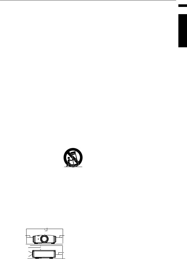
- Do not place this product on an unstable cart, stand, or table. The product may fall, causing serious injury to a child or adult, and serious damage to the product. The product should be mounted according to the manufacturer’s instructions, and should use a mount recommended by the manufacturer.
- When the product is used on a cart, care should be taken to avoid quick
stops, excessive force, and uneven surfaces which may cause the product and cart to overturn, damaging
equipment or causing possible injury to the operator.
-Slots and openings in the cabinet are provided for ventilation. These ensure reliable operation of the product and protect it from overheating. These openings must not be blocked or covered. (The openings should never be blocked by placing the product on bed, sofa, rug, or similar surface. It should not be placed in a built-in installation such as a bookcase or rack unless proper ventilation is provided and the manufacturer’s instructions have been adhered to.)
-To allow better heat dissipation, keep a clearance between this unit and its surrounding as shown below. When this unit is enclosed in a space of dimensions as shown below, use an air-conditioner so that the internal and external temperatures are the same. Overheating can cause
damage.
|
150 mm and above |
|
300 mm |
300 mm |
|
and above |
and above |
|
150 mm |
|
|
and above |
200 mm |
|
Front |
||
and above |
||
|
-Power source indicated on the label. If you are not sure of the type of power supply to your home, consult your product dealer or local power company.
-This product is equipped with a three-wire plug. This plug will fit only into a grounded power outlet. If you are unable to insert the plug into the outlet, contact your electrician to install the proper outlet. Do not defeat the safety purpose of the grounded plug.
-Power-supply cords should be routed so that they are not likely to be walked on or pinched by items placed upon or against them. Pay particular attention to cords at doors, plugs, receptacles, and the point where they exit from the product.
-For added protection of this product during a lightning storm, or when it is left unattended and unused for long periods of time, unplug it from the wall outlet and disconnect the cable system. This will prevent damage to the product due to lightning and power line surges.
-Do not overload wall outlets, extension cords, or convenience receptacles on other equipment as this can result in a risk of fire or electric shock.
-Never push objects of any kind into this product through openings as they may touch dangerous voltage points or short out parts that could result in a fire or electric shock. Never spill liquid of any kind on the product.
-Do not attempt to service this product yourself as opening or removing covers may expose you to dangerous voltages and other hazards. Refer all service to qualified service personnel.
-Unplug this product from the wall outlet and refer service to qualified service personnel under the following conditions:
a)When the power supply cord or plug is damaged.
b)If liquid has been spilled, or objects have fallen on the product.
c)If the product has been exposed to rain or water.
d)If the product does not operate normally by following the operating instructions. Adjust only those controls that are covered by the Operation Manual, as an improper adjustment of controls may result in damage and will often require extensive work by a qualified technician to restore the product to normal operation.
e)If the product has been dropped or damaged in any way.
f)When the product exhibits a distinct change in performance, this indicates a need for service.
-When replacement parts are required, be sure the service technician has used replacement parts specified by the manufacturer or with same characteristics as the original part. Unauthorized substitutions may result in fire, electric shock, or other hazards.
-Upon completion of any service or repairs to this product, ask the service technician to perform safety checks to determine that the product is in proper operating condition.
-The product should be placed more than one foot away from heat sources such as radiators, heat registers, stoves, and other products (including amplifiers) that produce heat.
-When connecting other products such as VCR’s, and DVD players, you should turn off the power of this product for protection against electric shock.
Started Getting
3

Started Getting
-Do not place combustibles behind the cooling fan. For example, cloth, paper, matches, aerosol cans or gas lighters that present special hazards when over heated.
-Do not look into the projection lens while the illumination lamp is turned on. Exposure of your eyes to the strong light can result in impaired eyesight.
-Do not look into the inside of this unit through vents (ventilation holes), etc. Do not look at the illumination lamp directly by opening the cabinet while the illumination lamp is turned on. The illumination lamp also contains ultraviolet rays and the light is so powerful that your eyesight can be impaired.
-Do not drop, hit, or damage the light-source lamp (lamp unit) in any way. It may cause the light-source lamp to break and lead to injuries. Do not use a damaged light source lamp. If the light-source lamp is broken, ask your dealer to repair it. Fragments from a broken light-source lamp may cause injuries.
-The light-source lamp used in this projector is a high pressure mercury lamp. Be careful when disposing of the light-source lamp. If anything is unclear, please consult your dealer.
-Do not ceiling-mount the projector to a place which tends to vibrate; otherwise, the attaching fixture of the projector could be broken by the vibration, possibly causing it to fall or overturn, which could lead to personal injury.
-Use only the accessory cord designed for this product to prevent shock.
-Once every three years, please perform an internal test. This unit is provided with replacement parts needed to maintain its function (such as cooling fans). Estimated replacement time of parts can vary greatly depending on frequency of use and the respective environment. For replacement, please consult your dealer, or the nearest authorized JVC service center.
-When fixing the unit to the ceiling, Please note that we do not take any responsibility, even during the warranty period, if the product is damaged due to use of metal fixtures used for fixation to the ceiling other than our own or if the installation environment of said metal fixtures is not appropriate. If the unit is suspended from the ceiling during use, please be careful in regard to the ambient temperature of the unit. If you use a central heating, the temperature close to the ceiling will be higher than normally expected.
-Video images can burn into the electronic component parts. Please do not display screens with still images of high brightness or high contrast, such as found in video games and computer programs. Over a long period of time it might stick to the picture element. There is no problem with the playback of moving images, e.g. normal video footage.
-Please power it on and let it run occasionally. Please avoid using the unit in a room where cigarettes are smoked. It is impossible to clean optical component parts if they are contaminated by nicotine or tar. This might lead to performance degradation.
* DO NOT allow any unqualified person to install the unit.
Be sure to ask your dealer to install the unit (e.g. attaching it to the ceiling) since special technical knowledge and skills are required for installation. If installation is performed by an unqualified person, it may cause personal injury or electrical shock.
4
POWER CONNECTION
For USA and Canada only
Use only the following power cord.
Power cord
The power supply voltage rating of this product is AC110V – AC240V. Use only the power cord designated by our dealer to ensure Safety and EMC. Ensure that the power cable used for the projector is the correct type for the AC outlet in your country. Consult your product dealer.
Power cord
For European continent countries
WARNING:
Do not cut off the main plug from this equipment.
If the plug fitted is not suitable for the power points in your home or the cable is too short to reach a power point, then obtain an appropriate safety approved extension lead or adapter or consult your dealer. If nonetheless the mains plug is cut off, dispose of the plug immediately, to avoid a possible shock hazard by inadvertent connection to the main supply. If a new main plug has to be fitted, then follow the instruction given below.
WARNING:
THIS APPARATUS MUST BE EARTHED.
IMPORTANT (Europe only):
The wires in the mains lead on this product are colored Vert et jaune in accordance with the following cord:
Green-and-yellow : Earth
Blue |
: Neutral |
Brown |
: Live |
As these colors may not correspond with the colored making identifying the terminals in your plug, proceed as follows:
The wire which is colored green-and-yellow must be connected to the terminal which is marked M with the letter E or the safety earth or colored green or green-and-yellow. The wire which is colored blue must be connected to the terminal which is marked with the letter N or colored black.
The wire which is colored brown must be connected to the terminal which is marked with the letter L or colored red.
Dear Customer,
This apparatus is in conformance with the valid European directives and standards regarding electromagnetic compatibility and electrical safety.
European representative of JVC KENWOOD Corporation is: JVC Technical Services Europe GmbH Konrad-Adenauer-Allee 1-11
61118 Bad Vilbel Germany
Started Getting
5
Started Getting
ENGLISH
Information on Disposal of Old Electrical and Electronic Equipment and Batteries (applicable for countries that have adopted separate waste collection systems)
Products and batteries with the symbol (crossed-out wheeled bin) cannot be disposed as household waste.
Old electrical and electronic equipment and batteries should be recycled at a facility capable of handling these items and their waste byproducts.
Contact your local authority for details in locating a recycle facility nearest to you.
Proper recycling and waste disposal will help conserve resources whilst preventing detrimental effects on our health and the environment.
Notice: The sign “Pb” below the symbol for batteries indicates that this battery contains lead.
DEUTSCH
Entsorgung von gebrauchten elektrischen und elektronischen Geräten und Batterien (anzuwenden in Ländern mit einem separaten Sammelsystem für solche Geräte)
Das Symbol (durchgestrichene Mülltonne) auf dem Produkt oder seiner Verpackung weist darauf hin, dass dieses Produkt nicht als normaler Haushaltsabfall behandelt werden darf. Die betreffenden Produkte müssen an einer Annahmestelle für das Recycling von elektrischen und elektronischen Geräten und Batterien abgegeben werden.
Weitere Informationen über das Recycling dieses Produktes erhalten Sie von Ihrer Gemeinde oder den kommunalen Entsorgungsbetrieben.
Unsachgemäße oder falsche Entsorgung gefährden Umwelt und Gesundheit.
Zur Beachtung: Das Zeichen „Pb“ unter dem Symbol für Batterien zeigt an, dass diese Batterie Blei enthalt.
FRANÇAIS
Information sur l’élimination des anciens équipements électriques et électroniques et piles électriques (applicable dans les pays de qui ont adopté des systèmes de collecte sélective)
Les produits et piles électriques sur lesquels le pictogramme (poubelle barrée) est apposé ne peuvent pas être éliminés comme ordures ménagères.
Les anciens équipements électriques et électroniques et piles électriques doivent être recyclés sur des sites capables de traiter ces équipements et leurs déchets par produit.
Contactez vos autorités locales pour connaître le site de recyclage le plus proche.
Un recyclage adapté et l’élimination des déchets aideront à conserver les ressources et à nous préserver des leurs effets nocifs sur notre santé et sur l’environnement.
Avis: Le symbole “Pb” ci-dessous sur des piles électrique indique que cette pile contient du plomb.
NEDERLANDS
Informatie over het weggooien van oude elektrische en elektronische apparaten en batterijen (voor landen die gescheiden afvalverzamelsystemen gebruiken)
Producten en batterijen met het (afvalcontainer met x-teken) symbool mogen niet als normaal huisvuil worden weggegooid.
Oude elektrische en elektronische apparaten en batterijen moeten worden gerecycled door een faciliteit die geschikt is voor het verwerken van dergelijke voorwerpen.
Raadpleeg de betreffende lokale instantie voor details aangaande in de buurt zijnde recylingfaciliteiten.
Het juist recyclen en weggooien van afval spaart natuurlijke bronnen en reduceert schadelijke invloed op uw gezondheid en het milieu.
Opmerking: De ”Pb” aanduiding onder het batterijsymbool betekent dat deze batterij lood bevat.
6
ESPAÑOL / CASTELLANO
Información acerca de la eliminación de equipos eléctricos, electrónicos y baterías al final de la vida útil (aplicable a los países de la que hayan adoptado sistemas independientes de recogida de residuos)
Los productos y las baterías con el símbolo (contenedor con ruedas tachado) no podrán ser desechados como residuos domésticos.
Los equipos eléctricos, electrónicos y baterías al final de la vida útil, deberán ser reciclados en instalaciones que puedan dar el tratamiento adecuado a estos productos y a sus subproductos residuales correspondientes.
Póngase en contacto con la autoridad local competente para obtener información sobre el centro de reciclaje más cercano.
El reciclaje y la disposición adecuada de los desechos ayuda a conservar los recursos naturales y a reducir los efectos perjudiciales en la salud y el medio ambiente.
Nota: El símbolo “Pb” debajo del símbolo en baterías indica que dicha batería contiene plomo.
ITALIANO
Informazioni sull’eliminazione dei prodotti elettrici ed elettronici e delle batterie (per i Paesi che adottano la raccolta differenziata dei rifiuti)
I prodotti e le batterie recanti questa icona (bidone carrellato della spazzatura con il simbolo della croce) non devono essere eliminati come rifiuti solidi urbani.
I prodotti elettrici ed elettronici e le batterie devono essere riciclati presso centri idonei alla loro gestione e a quella dei rispettivi sottoprodotti.
Per informazioni sul centro di riciclaggio più vicino si suggerisce di rivolgersi alle autorità locali. Se eseguiti adeguatamente, l’eliminazione e il riciclaggio dei rifiuti aiutano a conservare le risorse e al contempo impedire gli effetti nocivi sulla salute e l’ambiente.
Avviso: Il contrassegno “Pb” che appare sotto il simbolo delle batterie significa che contengono piombo.
Started Getting
7

|
Contents |
|
Getting |
|
|
|
Getting Started |
|
|
Safety Precautions .................................................. |
2 |
|
Accessories/Optional Accessories .......................... |
9 |
Started |
|
|
|
Check the Accessories ........................................ |
9 |
|
Optional Accessories ........................................... |
9 |
|
Controls and Features ........................................... |
10 |
|
Main Unit - Front ................................................ |
10 |
|
Main Unit - Bottom ............................................. |
10 |
|
Main Unit - Rear ................................................. |
11 |
|
Main Unit - Input Terminals ................................ |
12 |
|
Remote control (sold separately, model no. RM- |
|
|
MH13G) ............................................................. |
13 |
|
Loading Batteries into the Remote Control (Sold |
|
|
Separately) ........................................................ |
14 |
|
Effective Range of Remote Control (Sold |
|
|
Separately) ........................................................ |
14 |
|
Set up |
|
|
Installing the Projector ........................................... |
15 |
|
Precautions during Installation ........................... |
15 |
|
Precautions during Mounting ............................. |
17 |
|
Adjusting the Position ........................................ |
18 |
|
Connecting the Projector ....................................... |
19 |
|
Connecting to the HDMI Input Terminal (Digital |
|
|
Input) ................................................................. |
19 |
|
Connecting to the LAN Terminal ........................ |
20 |
|
Connecting to the RS-232C Terminal ................ |
20 |
|
Connecting to the REMOTE Terminal ............... |
20 |
|
Connecting the Power Cord (Supplied Accessory) |
|
|
........................................................................... |
21 |
|
Operate |
|
|
Viewing Videos ...................................................... |
22 |
|
Adjust/Set |
|
|
Adjustments and Settings in the Menu .................. |
24 |
|
List of Menu Items ............................................. |
24 |
Picture Adjust .................................................... |
25 |
Input Signal ........................................................ |
29 |
Installation ......................................................... |
31 |
Display Setup .................................................... |
36 |
Function ............................................................. |
37 |
Information ......................................................... |
38 |
Maintenance |
|
Replacing the Lamp .............................................. |
39 |
Lamp Replacement Procedure .......................... |
39 |
Resetting the Lamp Time ................................... |
41 |
Replacing the Attachment ................................. |
42 |
Maintaining the Cabinet and Remote Control (Sold |
|
Separately) ............................................................ |
47 |
Cleaning and Replacing the Filter ......................... |
48 |
Troubleshooting |
|
Troubleshooting .................................................... |
49 |
When the following messages appear... ................ |
51 |
Others |
|
External Control .................................................... |
52 |
RS-232C Specifications ..................................... |
52 |
TCP/IP Connection ............................................ |
52 |
Command Format .............................................. |
53 |
Remote Control Code ........................................ |
54 |
Communications Example ................................. |
55 |
Specifications ........................................................ |
56 |
Index ..................................................................... |
62 |
Symbols used in this manual |
|
Pindicates a function that is supported by DLA- |
|
VS2400ZG. |
|
Oindicates a function that is supported by DLA- |
|
VS2400G. |
|
Items not marked with any of the above symbols are |
|
supported by all models. |
|
8
Accessories/Optional Accessories
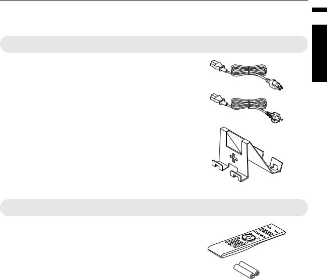
Check the Accessories
Power cord (for USA) (about. 2 m) ......................................... |
1 piece |
Power cord (for EU) (about. 2 m) ............................................ |
1 piece |
Lamp attachment “UPPER 45-90 & REVERSE” (Use Area: B, Refer to p. 15) and Installation verification sticker ................................ 1 piece
0 INSTRUCTIONS (this book), warranty card, and other printed material are also included.
Optional Accessories
0 Remote control: Model no. RM-MH13G
0 AAA-size battery
0 Replacement lamp: model PK-L2313U
Started Getting
9
Controls and Features
Started Getting
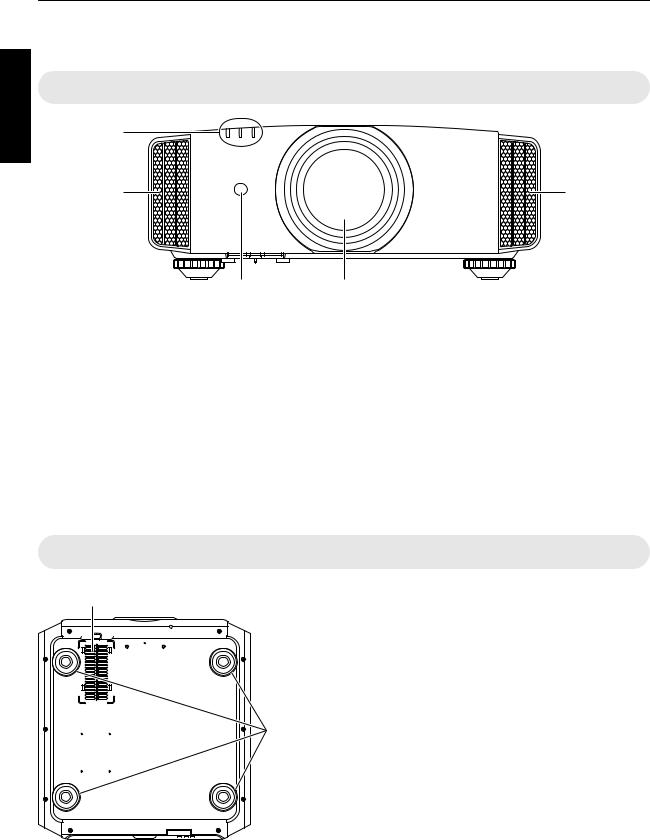
Main Unit - Front
D
E |
E |
C |
AB |
A Lens P
This is a projection lens. Do not look through the lens while an image is projected.
0 For O, the lens is sold separately.
B Lens sheet
The lens comes attached with a protective sheet when you purchase this product.
C Remote Sensor (front)
Please aim the remote control (sold separately) at this area when using it.
* There is also a remote sensor at the rear.
Main Unit - Bottom
D Indicator
Refer to “Indicator Display on the Main Unit”p. 59.
E Exhaust vent
Warm air is discharged to cool down the internal temperature.
Do not block the vents.
F |
F Inlets (at 3 points on the rear/bottom)
The inlets take in air to cool down the internal temperature.
Do not block or prevent the outflow of hot air. Doing so may cause the unit to malfunction.
* There are two inlets on the right and left sides at the rear of the unit.
|
G Feet |
|
The height and angle of the projector can be adjusted by turning the |
G |
foot. (0 to 5 mm) (p. 18) |
|
When the foot is removed, it can be used as the mounting holes for |
|
the ceiling mount bracket. |
10
Main Unit - Rear |
|
Started Getting |
F |
F |
|
|
|
|
|
I |
|
H |
L K J |
|
H Input terminals
For details on the terminals. refer to “Main Unit - Input Terminals”p. 12.
I Lamp cover
When replacing the light source lamp, remove this cover.
K Remote Sensor (rear)
Please aim the remote control (sold separately) at this area when using it.
* There is also a remote sensor at the front.
L Power input terminal
Connect the supplied power cord to this terminal.
J Operation panel
For more details, please refer to the “Operation panel” in the diagram below.
Operation panel

 A [STANDBY/ON]: Turns “on”/“off” the
power
 [INPUT]: Switches the input
 [OK]: Confirms a selection
 [JKH I] keys: Selects an item
[MENU]: Displays the menu |
[BACK]: Returns to the previous menu |
11
Started Getting
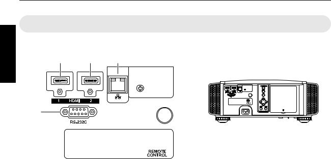
Main Unit - Input Terminals
Enlarged View of Rear Face
A B C
D
 E
E
A [HDMI 1] input terminal
B [HDMI 2] input terminal
For connecting to devices that support HDMI output. (p. 19)
It is fitted to the M3 lock hole. The depth of the screw hole is 3 mm.
C [LAN] terminal (RJ-45)
The projector can be controlled by connecting it to a PC through the computer network for control commands to be sent to the projector.
D [RS-232C] terminal (D-sub 9-pin male)
The projector can be controlled by connecting a PC to this terminal.
E [REMOTE] terminal (stereo mini jack)
This terminal is used to connect the remote control directly to the projector with the cable.
12
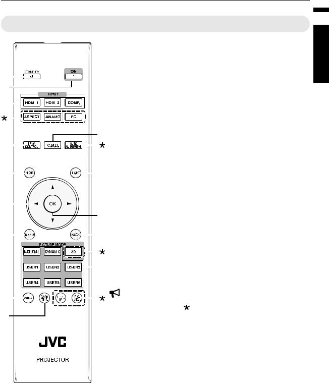
Remote control (sold separately, model no. RM-MH13G)
A B [STAND BY] |
J [C.M.D.] |
|
|
|
|
|
|
|
|
|
|
|
|
|
|
|
|
|
|
|
|
|
|
|
|
|
|
|
|
Turns off the power. (p. 23) |
|
|
|
|
|
|
|
|
|
|
|
|
|
|
|
|
|
|
|
|
|
|
|
|
|
|
|
|
|
B C [ON] |
|
A |
|
|
|
|
|
|
|
|
|
|
|
|
|
|
|
Turns on the power. (p. 22) |
|||||||||||||
|
|
|
|
|
|
|
|
|
|
|
|||||||||||||||||||
B |
|
|
|
|
|
|
|
|
C [INPUT] |
||||||||||||||||||||
|
|
|
|
|
|
|
|
|
|
|
|
|
|
|
|
|
|
|
|
|
|
|
|
|
|
|
|
Select an input from [HDMI 1], |
|
|
|
|
|
|
|
|
|
|
|
|
|
|
|
|
|
|
|
|
|
|
|
|
|
|
|
|
|
||
C |
|
|
|
|
|
|
|
|
|
|
|
|
|
|
|
|
|
|
|
|
|
[HDMI 2], and [Dual]. (p. 22) |
|||||||
|
|
|
|
|
|
|
|
|
|
|
|
|
|
|
|
|
|
|
|
||||||||||
|
|
|
|
|
|
|
|
|
|
|
|
|
|
|
|
|
|
|
|
|
|
|
|
|
|
|
|
D [LENS CONTROL] |
|
|
|
|
|
|
|
|
|
|
|
|
|
|
|
|
|
|
|
|
|
|
|
|
|
|
|
|
|
|
P |
|
|
|
|
|
|
|
|
|
|
|
|
|
|
|
|
|
|
|
|
|
|
|
|
|
|
|
J |
For adjusting focus, zoom, and |
|
D |
|
|
|
|
|
|
|
|
|
|
|
|
|
|
|
|
|
|
|
|
|
|
|
|
|
|
|
shift. (p. 31) |
|
|
|
|
|
|
|
|
|
|
|
|
|
|
|
|
|
|
|
|
|
|
|
|
|
|
|
|
|
E [HIDE] |
|
|
|
|
|
|
|
|
|
|
|
|
|
|
|
|
|
|
|
|
|
|
|
|
|
|
|
|
|
Hides the image temporarily. |
|
|
|
|
|
|
|
|
|
|
|
|
|
|
|
|
|
|
|
|
|
|
|
|
|
|
|
|
|
(p. 22) |
|
E |
|
|
|
|
|
|
|
|
|
|
|
|
|
|
|
|
|
|
|
|
K F [JKH I] keys |
||||||||
|
|
|
|
|
|
|
|
|
|
|
|
|
|
|
|
|
|
|
|
|
|||||||||
F |
|
|
|
|
|
|
|
|
For selecting an item. |
||||||||||||||||||||
|
|
|
|
|
|
|
|
G |
[MENU] |
||||||||||||||||||||
|
|
|
|
|
|
|
|
|
|
|
|
|
|
|
|
|
|
|
|
|
|
|
|
|
|
|
|
|
|
|
|
|
|
|
|
|
|
|
|
|
|
|
|
|
|
|
|
|
|
|
|
|
|
|
|
|
|
Displays the menu, |
|
|
|
|
|
|
|
|
|
|
|
|
|
|
|
|
|
|
|
|
|
|
|
|
|
|
|
|
|
||
|
|
|
|
|
|
|
|
|
|
|
|
|
|
|
|
|
|
|
|
|
|
|
|
|
|
|
L or hides the menu if it is |
||
|
|
|
|
|
|
|
|
|
|
|
|
|
|
|
|
|
|
|
|
|
|
|
|
|
|
|
|
displayed. |
|
G |
|
|
|
|
|
|
|
|
|
|
|
|
M H [GAMMA] |
||||||||||||||||
|
|
|
|
|
|
|
|||||||||||||||||||||||
|
|
|
|
|
|
|
|
|
|
|
|
|
|
|
|
|
|
|
|
|
|
|
|
|
|
|
|
For setting the gamma level. |
|
|
|
|
|
|
|
|
|
|
|
|
|
|
|
|
|
|
|
|
|
|
|
|
|
|
|
|
|
(p. 27) |
|
|
|
|
|
|
|
|
|
|
|
|
|
|
|
|
|
|
|
|
|
|
|
|
|
|
|
|
N |
I [COLOR TEMP] |
|
|
|
|
|
|
|
|
|
|
|
|
|
|
|
|
|
|
|
|
|
|
|
|
|
|
|
|
For setting the color |
||
|
|
|
|
|
|
|
|
|
|
|
|
|
|
|
|
|
|
|
|
|
|
|
|
|
|
|
|||
|
|
|
|
|
|
|
|
|
|
|
|
|
|
|
|
|
|
|
|
|
|
|
|
|
|
|
|
temperature. (p. 27) |
|
For setting frame interpolation. (p. 28)
K [LIGHT]
Illuminates the buttons on the remote control.
L [OK]
Confirms a selected item.
M [BACK]
Returns to the previous menu.
N [PICTURE MODE]
Switches the Picture mode to [NATURAL], [DYNAMIC], [USER1] to [USER6]. (p. 25)
H |
|
|
|
|
|
|
|
CAUTION |
|
|
|
|
|||||||
|
|
|
|
|
|
|
|||
|
Buttons indicated with a |
mark are not usable on this unit. |
|||||||
0 |
|||||||||
I |
However, the [LENS AP.] and [PIC. ADJ.] buttons can be used during pixel |
||||||||
|
|
|
|
|
|
|
|
adjustment. |
|
Started Getting
13
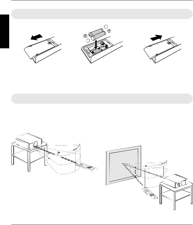
Loading Batteries into the Remote Control (Sold Separately)
Started Getting
0If the remote control has to be brought closer to the projector to operate, it means that the batteries are wearing out. Replace the batteries with new ones (AAA).
0Insert the batteries according to the t s marks. Be sure to insert the s end first.
0If an error occurs while using the remote control, remove the batteries and wait for five minutes. Load the batteries again and operate the remote control.
Effective Range of Remote Control (Sold Separately)
When aiming the remote control toward the sensor on this unit (front or rear), ensure that the distance to the sensor is within 7 m.
If the remote control fails to work properly, move closer to this unit.
This unit
30° 
30°
 20°
20°
 20°
20°
Remote Control
Control through reflection off a screen, etc.
Ensure that the total of distance A (between this unit and the screen) and distance B (between the remote control and the screen) is within 7 m.
*As the efficiency of signals reflected from the remote control unit varies with the type of screen used, the operable distance may decrease.
|
|
Screen |
|
|
|
||
|
|
|
|
30° |
30° |
|
This unit |
|
|
|
|
|
|||
|
|
|
|
|
|
||
|
|
|
|
|
|||
|
20° |
|
|
A |
|
|
|
|
|
|
|
|
|||
|
20° |
|
|
|
|
|
|
|
|
|
|
|
|
|
|
|
B |
|
|
|
|
|
|
Remote Control |
|
|
|
||||
|
|
|
|||||
|
|
|
|||||
|
|
|
|||||
|
|
|
|
|
|
|
|
 CAUTION
0 Do not put the remote control in a place with an exposure to direct sun light or high temperature.
14
Installing the Projector
Precautions during Installation
Please read the following carefully before installing this unit.
Do not install at the following
This unit is a precision device. Please refrain from installing or using it at the following locations. Otherwise, it may cause fire or malfunction.
0Dusty, wet and humid places
0Places subject to oily smoke or cigarette smoke
0On top of a carpet or bedding, or other soft surfaces
0Places exposed to direct sunlight
0Places with a high or low temperature
0Do not install this unit in a room that is oily or subject to cigarette smoke. Even a small quantity of smoke or oiliness can have a long-term impact on this unit.
*This unit produces a great amount of heat, and is designed to take in cool air to cool its optical components. Using the unit at the above locations may cause dirt to attach to the light path, thereby resulting in dark images or dull colors.
*Dirt that sticks to the optical components cannot be removed.
Maintain clearance from the wall, etc.
As the unit discharges a large amount of heat, install it with adequate clearance from the surroundings as shown below.
|
150 mm and above |
|
300 mm |
300 mm |
|
and above |
and above |
|
150 mm |
|
|
and above |
200 mm |
|
Front |
||
and above |
||
|
Leave the front area of the unit unblocked.
If there is any obstructing object in front of the exhaust vent, hot air will flow back to the unit and cause it to heat up. Hot air flowing out of the unit may cast shadows on the screen (heat haze phenomenon).
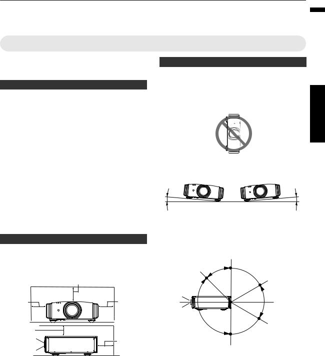
Using the projector
This unit uses a projection lamp, which will heat up when in use.
Please refrain from projecting in the following circumstances. Otherwise, it may cause fire or malfunction.
0 |
Projection with the unit stood vertically |
||
|
|
|
upSet |
|
|
|
|
0 |
Projection with the unit inclined at an angle |
||
Install the unit such that the tilt in the horizontal direction (left or right) is within ±10°.
10° |
10° |
As shown in the illustration, this unit can be installed with a tilted angle, but for some areas there might be other conditions. Moreover, depending on the angle of installation, it may be necessary to have a hanging metal mount and secure installation base depending on the angle of the installation.
Area B |
90 ° |
45 ° |
30 ° |
Area B
Area A
-30 °
Area A : Use the factory-installed lamp. The lamp is attached to the Area A attachment (X mark and “0°” marking).
Area B : Replace with the supplied attachment (+ mark and “90°” marking).
Refer to p. 42 on the replacement procedures.
15
up Set
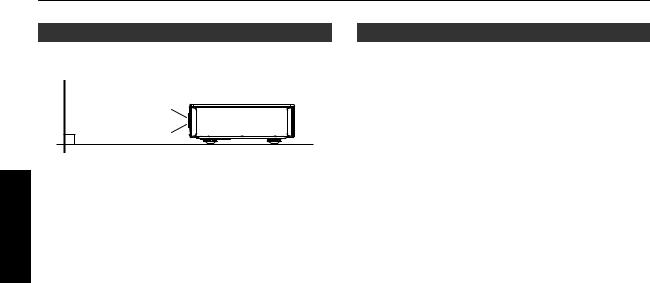
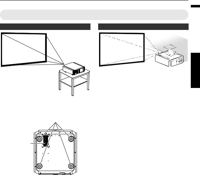
Installing the screen
Install the unit and the screen such that they are perpendicular to each other.
Screen
Front
0Please choose a screen material with non-uniform patterns. Uniform patterns such as checks may cause interference patterns to occur.
0In this case, you can change the size of the screen to make the interference patterns less noticeable.
Using the projector at a high altitude
When using this unit at a location that is higher than 900 m above sea level (low air pressure), set the “High Altitude Mode” to “On”. (p. 36)
16
Precautions during Mounting
Securing (mounting) the projector
0Make sure to secure the main unit to prevent accidents such as during an earthquake.
Securing with screws
4 Locations
Air Inlets
Remove the four feet at the bottom, and fasten using the screws (M5 screws, 13 to 23 mm).
*Using screws other than those designated may cause the unit to break down.
*Leave a clearance of at least 10 mm from the bottom surface of the unit to allow it to take in cool air.
Securing the projector (ceiling mount)
0Be sure to ask your dealer to install the unit for you. Installing the unit on your own may cause the unit to fall resulting in injury.
0Take the necessary actions to prevent the main unit from falling off such as during an earthquake.
0Regardless of the warranty period, JVC is not liable for any product damage caused by mounting the unit with non-JVC ceiling fittings or to an environment that is not suited for ceiling mount.
0When using the unit with it suspended from a ceiling, pay attention to the surrounding temperature. When a heater is in use, the temperature around the ceiling may be higher than expected.
0To attach the unit to the ceiling mount bracket, set the torque between the range of 1.5N m to 2.0N m. Tightening with torque exceeding the above range may cause damage to the unit, which may result the unit to fall.
up Set
17
Adjusting the Position
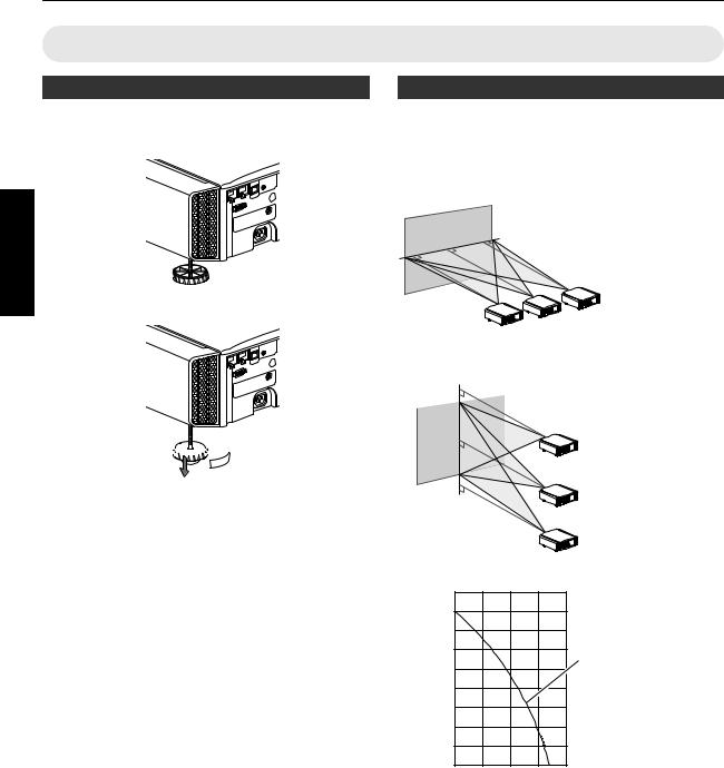
Adjusting the elevation angle of the projector
The height and inclination of the unit (0 to 5 mm) can be adjusted by turning the feet.
Lift the unit and adjust the four feet.
up Set


 Feet
Feet
Extend 


 Contract
Adjusting the position of the image
By using the lens shift feature of this unit, you can shift the image upward/downward or to the left/right. Set it to your preferred position.
■ Horizontal Position
Vertical Position: 0% (Center)
Up to about 34% of the projected image
■ Vertical Position
Horizontal Position: 0 % (Center)
Up to about 80% of the projected image
■ Lens shift Range |
|
|
|||
|
90 |
|
|
|
|
(%) |
80 |
|
|
|
|
70 |
|
|
|
|
|
shift |
60 |
|
|
|
Lens movement range |
|
|
|
|
||
lens |
50 |
|
|
|
|
40 |
|
|
|
|
|
Vertical |
30 |
|
|
|
|
|
|
|
|
|
|
|
20 |
|
|
|
|
|
10 |
|
|
|
|
|
0 |
10 |
20 |
30 |
40 |
|
Horizontal lens shift (%) |
||||
0The maximum vertical shift varies with the amount of horizontal shift. Similarly, the maximum horizontal shift also changes with the amount of vertical shift.
0The values on the graph are intended as a guide. Use them for reference during installation.
0To adjust the screen position, it is recommended to wait till the position becomes stable after projection before adjusting. The position may changed after projection depending on the attitude of the projector.
18
Connecting the Projector
0Do not turn on the power until connection is complete.
0The connection procedures differ according to the device used. For details, please refer to the instruction manual of the device to be connected.
0This projector is used for projecting images. To output the audio of connected devices, please connect a separate audio output device, such as an amplifier or speaker.
0The images may not be displayed depending on the devices and cables to be connected. Use only HDMI cables (sold separately) that are HDMI-certified.
0Some cables cannot be connected to this unit due to the size of their connector cover.
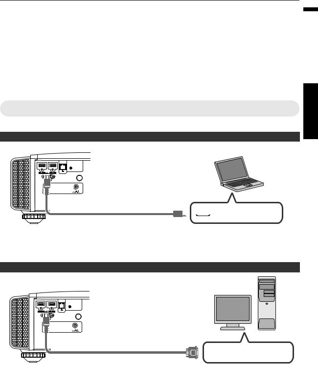
Connecting to the HDMI Input Terminal (Digital Input)
Connecting via HDMI cable
This Unit |
Laptop, etc. |
|
To [HDMI 1] or [HDMI 2] input terminal
Or both [HDMI1] and [HDMI2]


 HDMI Output Terminal HDMI Cable (Sold Separately)
0If noise occurs, move the laptop away from this unit.
0For a transmission bandwidth in compliance with the HDMI standard, a 340 MHz cable is recommended.
0If the video is not displayed, try to reduce the length of the cable.
Connecting via HDMI-DVI conversion cable
This Unit
To [HDMI 1] or [HDMI 2] input terminal |
Or both [HDMI1] and [HDMI2] |
HDMI-DVI Conversion Cable (Sold Separately)
Desktop PC, etc.
 DVI Output Terminal
0If noise occurs, move the desktop PC away from this unit.
0If the video is not displayed, try to reduce the length of the cable.
up Set
19

Connecting to the LAN Terminal
up Set
This Unit |
Hub |
|
To [LAN] Terminal |
||
|
||
|
Network |
|
|
Connection Cable |
|
|
(Sold Separately) |
|
|
Server |
|
|
Desktop PC, etc. |
0The network is used to control this unit. It is not used for sending or receiving video signals.
0Please contact your network administrator for information concerning the network connection.
0For more information on control, please refer to “External Control” (p. 52).
Connecting to the RS-232C Terminal
This Unit
Laptop, etc.
 To [RS-232C] Terminal
RS-232C Terminal
RS-232C Connection Cable (Sold Separately)
0 For more information on control, please refer to “External Control” (p. 52).
Connecting to the REMOTE Terminal
This Unit
 To [REMOTE] Terminal
Connection Cable
(Sold Separately)
0 For more details on the wired remote controller and connection cable, please consult your dealer.
20
Loading...