


 Loading...
JVC DR-MH300BE, DR-MH300BEK, DR-MH300SE, DR-MH300SEF, DR-MH300SEK service manual
...SERVICE MANUAL
HDD&DVD VIDEO RECORDER
DR-MH300BE, DR-MH300BEK, DR-MH300SE,DR-MH300SEF, DR-MH300SEK,DR-MH300SER, DR-ED400SE
|
|
|
|
|
|
|
Area Suffix |
|
|
|
|
|
|
E |
Continental Europe |
Only ver.E,EF,EK |
|
Only ver.EK |
|
Only ver.ER |
|||
|
|
|
|
|
|
EF |
Northern Europe |
|
|
|
|
|
|
||
|
|
|
|
|
|
||
|
|
|
|
|
|
||
|
|
TM |
|
France |
|||
|
|
|
|
|
|
------------------------EK |
U.K. |
|
|
|
|
|
|
----ER |
Russian Federation |
Only ver.E,EF,ER
TM
PR
|
|
|
RAM/RW |
|
STANDBY/ON |
HDD |
DVD |
NAVIGATION GUIDE |
ENTER |
PUSH-OPEN
PR
DR-MH300BE, DR-MH300BEK, DR-MH300SE, DR-MH300SEF,
DR-MH300SEK, DR-MH300SER, DR-ED400SE [D5HR10]
Since the whole mechanism assembly unit is replaced, the DVD recorder mechanism of this unit need not be adjusted.
TABLE OF CONTENTS
1 PRECAUTION. . . . . . . . . . . . . . . . . . . . . . . . . . . . . . . . . . . . . . . . . . . . . . . . . . . . . . . . . . . . . . . . . . . . . . . . . 1-3 2 SPECIFIC SERVICE INSTRUCTIONS . . . . . . . . . . . . . . . . . . . . . . . . . . . . . . . . . . . . . . . . . . . . . . . . . . . . . . 1-6 3 DISASSEMBLY . . . . . . . . . . . . . . . . . . . . . . . . . . . . . . . . . . . . . . . . . . . . . . . . . . . . . . . . . . . . . . . . . . . . . . . 1-7 4 ADJUSTMENT . . . . . . . . . . . . . . . . . . . . . . . . . . . . . . . . . . . . . . . . . . . . . . . . . . . . . . . . . . . . . . . . . . . . . . . 1-10 5 TROUBLESHOOTING . . . . . . . . . . . . . . . . . . . . . . . . . . . . . . . . . . . . . . . . . . . . . . . . . . . . . . . . . . . . . . . . . 1-11
COPYRIGHT © 2005 Victor Company of Japan, Limited
No.YD089
2005/12
SPECIFICATION
|
DR-MH300SER |
|
DR-MH300BE,DR-MH300SE,DR-ED400SE |
DR-MH300SEF |
DR-MH300BEK,DR-MH300SEK |
|
|
|
|
|
|
GENERAL |
|
|
|
|
|
Power requirement |
AC 220 V - 240 V~, 50 Hz/60 Hz |
|
|
|
|
Power consumption |
Power on : 36 W |
|
|
|
|
|
Power off : 6.4 W |
|
|
|
|
Temperature |
Operating : 5°C to 35°C |
|
|
|
|
|
Storage : -20°C to 60°C |
|
|
|
|
Operating position |
Horizontal only |
|
|
|
|
Dimensions (W × H × D) |
435 mm × 70 mm × 300 mm |
|
|
|
|
Weight |
4.6 kg |
|
|
|
|
VIDEO/AUDIO (DVD Deck) |
|
|
|
|
|
Recordable disc |
DVD-RAM 12 cm (4.7 GB/9.4 GB*1),DVD-RAM 8 cm (1.4 GB/2.8 GB*2),DVD-R 12 cm (4.7 GB),DVD-R 8 cm (1.4 GB),DVD-RW 12 |
||||
|
cm (4.7 GB),DVD-RW 8 cm (1.4 GB) |
|
|
||
|
*1 9.4 GB double-sided discs |
|
|
|
|
|
*2 2.8 GB double-sided discs |
|
|
|
|
Recording format |
DVD-RAM : DVD Video Recording format |
|
|
||
|
DVD-R : DVD Video format, DVD Video Recording format |
|
|
||
|
DVD-RW : DVD Video format, DVD Video Recording format |
|
|
||
Recording time |
Maximum 8 hours (with 4.7 GB disc) |
|
|
||
|
(XP) : Approx. 1 hour, (SP) : Approx. 2 hours, (LP) : Approx. 4 hours, (EP) : Approx. 6 hours, (FR) : Approx. 1 hour - 8 hours |
||||
Audio recording system |
Dolby Digital (2 ch) |
|
|
|
|
|
Linear PCM (XP mode only) |
|
|
|
|
Video recording compression system |
MPEG2 (CBR/VBR) |
|
|
|
|
VIDEO/AUDIO (HDD Deck) |
|
|
|
|
|
Capacity |
160 GB |
|
|
|
|
Recording time |
(DV) : Approx. 11 hours,(XP) : Approx. 34 hours,(SP) : Approx. 69 hours,(LP) : Approx. 138 hours, |
|
|||
|
(EP) : Approx. 209 hours,(FR480) : Approx. 300 hours |
|
|
||
Audio recording system |
Dolby Digital (2 ch) |
|
|
|
|
|
Linear PCM (XP mode only) |
|
|
|
|
Video recording compression system |
MPEG2 (VBR) |
|
|
|
|
Input/Output |
|
|
|
|
|
21-pin SCART connectors |
IN/OUT X 1, IN/DECODER X 1 |
|
|
|
|
S-video input |
Y:1.0 Vp-p,75 ohms |
|
|
|
|
|
C : 0.3Vp-p, 75 ohms |
|
|
|
|
Video input |
1.0 Vp-p, 75 ohms (pin jack) |
|
|
|
|
Audio input |
2 Vrms (pin jack) |
|
|
|
|
i.Link |
4-pin for DV Input/Output |
|
|
|
|
Component video output |
Y : 1.0 Vp-p, 75 ohms |
|
|
|
|
|
PB/PR: 0.7 Vp-p, 75 ohms |
|
|
|
|
|
Corresponding to copy protection |
|
|
||
HDMI output |
19-pin, Corresponding to HDCP |
|
|
|
|
|
Video : 576i/576p/1080i/720p |
|
|
|
|
|
Audio : 2 ch PCM/Bitstream |
|
|
|
|
Digital audio output |
Coaxial |
|
|
|
|
|
Corresponding to Dolby Digital and DTS Digital Surround, |
|
|
||
|
Bit stream |
|
|
|
|
|
Selectable in digital audio output setting menu |
|
|
||
G-LINK |
- |
|
3.5 mm Jack |
|
|
TUNER/TIMER |
|
|
|
|
|
Tuning system |
Frequency synthesised tuner |
|
|
|
|
Signal system |
PAL/SECAM colour signal, 625 lines/50 fields |
|
PAL colour signal,625 lines/50 fields |
||
TV channel storage capacity |
99 positions (+AUX position) |
|
|
|
|
Channel coverage |
- |
|
|
VHF(LOW):49 MHz-65 MHz(2-4) |
- |
(SECAM-L) |
|
|
|
VHF(HIGH):104 MHz-300 MHz(5- |
|
|
|
|
|
10CATV) |
|
|
|
|
|
Hyper:300 MHz-470 MHz(CATV) |
|
|
|
|
|
UHF:470 MHz-862 MHz(21-69) |
|
Channel coverage(PAL) |
VHF : 47 MHz - 89 MHz/ |
|
VHF(LOW):47 MHz-89 MHz |
VHF : 44.5MHz - 143MHz/ |
|
|
104 MHz - 300 MHz/ |
|
(E2-E4,X,Y,Z) |
143MHz - 470MHz/ |
|
|
302 MHz - 470 MHz |
|
VHF(HIGH):104 MHz-300 MHz |
UHF : 470MHz - 862MHz |
|
|
UHF : 470MHz - 862MHz |
|
(E5-E12,S1-S20,M1-M10,U1-U10) |
|
|
|
|
|
|
Hyper:302 MHz-470 MHz(S21-S41) |
|
|
|
|
|
UHF:470 MHz-862 MHz(E21-E69) |
|
Memory backup time |
Approx. 10 minutes. |
|
|
|
|
E.& O.E. Design and specifications subject to change without notice.
•Manufactured under license from Dolby Laboratories. “Dolby” and the double-D symbol are trademarks of Dolby Laboratories.
•“DTS” and “DTS Digital Out” are trademarks of Digital Theater Systems, Inc.
•This product incorporates copyright protection technology that is protected by U.S. patents and other intellectual property rights. Use of this copyright protection technology must be authorized by Macrovision. Reverse engineering or disassembly is prohibited.
•GUIDE Plus+, SHOWVIEW,VIDEO Plus+, G-LINK are (1) registered trademarks or trademarks of, (2) manufactured under license from and (3) subject of various international patents and patent applications owned by, or licensed to, Gemstar-TV Guide International, Inc. and/or its related affiliates.
•GEMSTAR-TV GUIDE INTERNATIONAL, INC. AND/OR ITS RELATED AFFILIATES ARE NOT IN ANY WAY LIABLE FOR THE ACCURACY OF THE PROGRAM SCHEDULE INFORMATION PROVIDED BY THE GUIDE PLUS+ SYSTEM. IN NO EVENT SHALL GEMSTAR-TV GUIDE INTERNATIONAL, INC. AND /OR ITS RELATED AFFILIATES BE LIABLE FOR ANY AMOUNTS REPRESENTING LOSS OF PROFITS, LOSS OF BUSINESS, OR INDIRECT, SPECIAL, OR CONSEQUENTIAL DAMAGES IN CONNECTION WITH THE PROVISION OR USE OF ANY INFORMATION, EQUIPMENT, OR SERVICES RELATING TO THE GUIDE PLUS+ SYSTEM.
•i-LINK is a trademark of Sony Corp .
•HDMI is a trademark of HDMI Licensing, LLC .
1-2 (No.YD089)
SECTION 1 PRECAUTION
1.1Safety Precautions
(1)This design of this product contains special hardware and many circuits and components specially for safety purposes. For continued protection, no changes should be made to the original design unless authorized in writing by the manufacturer. Replacement parts must be identical to those used in the original circuits. Services should be performed by qualified personnel only.
(2)Alterations of the design or circuitry of the product should not be made. Any design alterations of the product should not be made. Any design alterations or additions will void the manufacturers warranty and will further relieve the manufacture of responsibility for personal injury or property damage resulting therefrom.
(3)Many electrical and mechanical parts in the products have special safety-related characteristics. These characteristics are often not evident from visual inspection nor can the protection afforded by them necessarily be obtained by using replacement components rated for higher voltage, wattage, etc. Replacement parts which have these special safety characteristics are identified in the Parts List of Service Manual. Electrical components having such features are identified by shading on the schematics and by (  ) on the Parts List in the Service Manual. The use of a substitute replacement which does not have the same safety characteristics as the recommended replacement parts shown in the Parts List of Service Manual may create shock, fire, or other hazards.
(4)The leads in the products are routed and dressed with ties, clamps, tubings, barriers and the like to be separated from live parts, high temperature parts, moving parts and/or sharp edges for the prevention of electric shock and fire hazard. When service is required, the original lead routing and dress should be observed, and it should be confirmed that they have been returned to normal, after reassembling.
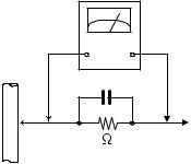
(5)Leakage shock hazard testing
After reassembling the product, always perform an isolation check on the exposed metal parts of the product (antenna terminals, knobs, metal cabinet, screw heads, headphone jack, control shafts, etc.) to be sure the product is safe to operate without danger of electrical shock.Do not use a line isolation transformer during this check.
•Plug the AC line cord directly into the AC outlet. Using a "Leakage Current Tester", measure the leakage current from each exposed metal parts of the cabinet, particularly any exposed metal part having a return path to the chassis, to a known good earth ground. Any leakage current must not exceed 0.5mA AC (r.m.s.).
•Alternate check method
Plug the AC line cord directly into the AC outlet. Use an
AC voltmeter having, 1,000Ω per volt or more sensitivity in the following manner. Connect a 1,500Ω 10W resistor paralleled by a 0.15µF AC-type capacitor between an exposed metal part and a known good earth ground.
Measure the AC voltage across the resistor with the AC
voltmeter.
Move the resistor connection to each exposed metal part, particularly any exposed metal part having a return path to the chassis, and measure the AC voltage across the resistor. Now, reverse the plug in the AC outlet and repeat each measurement. Voltage measured any must not exceed 0.75 V AC (r.m.s.). This corresponds to 0.5 mA AC (r.m.s.).
AC VOLTMETER (Having 1000 ohms/volts,
or more sensitivity)
0.15 F AC TYPE
|
Place this |
|
probe on |
1500 10W |
each exposed |
metal part. |
Good earth ground
1.2Warning
(1)This equipment has been designed and manufactured to meet international safety standards.
(2)It is the legal responsibility of the repairer to ensure that these safety standards are maintained.
(3)Repairs must be made in accordance with the relevant safety standards.
(4)It is essential that safety critical components are replaced by approved parts.
(5)If mains voltage selector is provided, check setting for local voltage.
1.3Caution
Burrs formed during molding may be left over on some parts of the chassis.
Therefore, pay attention to such burrs in the case of preforming repair of this system.
1.4Critical parts for safety
In regard with component parts appearing on the silk-screen printed side (parts side) of the PWB diagrams, the parts that are printed over with black such as the resistor (  ), diode (
  ) and ICP (
  ) or identified by the "
  " mark nearby are critical for safety. When replacing them, be sure to use the parts of the same type and rating as specified by the manufacturer.
(This regulation dose not Except the J and C version)
(No.YD089)1-3

1.5Important for laser products
1.CLASS 1 LASER PRODUCT
2.DANGER : Invisible laser radiation when open and inter lock failed or defeated. Avoid direct exposure to beam.
3.CAUTION : There are no serviceable parts inside the Laser Unit. Do not disassemble the Laser Unit. Replace the complete Laser Unit if it malfunctions.
4.CAUTION : The CD,MD and DVD player uses invisible laser radiation and is equipped with safety switches which prevent emission of radiation when the drawer is open and the safety interlocks have failed or are defeated. It is dangerous to defeat the safety switches.
5.CAUTION : If safety switches malfunction, the laser is able
to function.
6.CAUTION : Use of controls, adjustments or performance of procedures other than those specified here in may result in hazardous radiation exposure.
! |
|
Please use enough caution not to |
|||
|
|
|
|
|
|
|
|
see the beam directly or touch it |
|||
|
|
in case of an adjustment or operation |
|||
|
|
check. |
|||
|
|
|
|
|
|
|
|
|
|
|
|
|
|
|
|
|
|
REPRODUCTION AND POSITION OF LABEL
On mechaism assembly
1-4 (No.YD089)
1.6Hard Disk Drive (HDD) Handling Precautions
The HDD is a precision device for use in reading and writing a large amount of data on or from a disk rotating at a high speed. If it is not handled carefully, either abnormal operation may result or it may not be possible to read data. The HDD is sensitive to the following items and special care is required in safeguarding against them when handling an HDD. Also take care in handling a set incorporating an HDD.
(1)Vibrations and impacts
(2)Static electricity
(3)Rough handling
1.6.1 Handling in transport, etc.
•Be sure to place the HDD in the manufacturer's specified package carton before transport.
•When receiving a package containing an HDD, check that the package carton is not damaged (such as having holes in the carton, crushed corners, etc.).
•Do not impact the packaging carton when loading or unloading it.
•It is not permitted to use the inner package carton only for transporting an HDD.
•Do not stack package cartons one upon another.
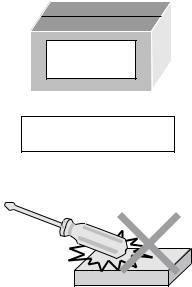
1.6.2 Handling an HDD in the stand-alone status
•When handling an HDD on a hard workbench, place an antistatic mat (rubber sheet) or similar object on the hard surface (to prevent any impacts occurring between the HDD and bench).
•Do not stack the HDDs one upon another.
•Do not knock an HDD with a hard object (such as a screwdriver).
•Do not place an HDD on its side panel without using a support (do not place an HDD in an unstable position).
1.6.3 Handling the installation of an HDD
HDD
Do not throw or drop packages.
Be sure to package and transport the HDDs correctly.
•Place antistatic mats or similar sheets on all of the surfaces on which work is conducted or when the HDD is transported.
•Do not permit the HDD to knock against the set's brackets.
•When screwing the brackets, be careful not to knock the HDD. When using a power screwdriver, use a low-shock model and arrange the tightening torque properly.
•When mounting an HDD in a main body, take care not to apply excessive force to the brackets.
(No.YD089)1-5
SECTION 2
SPECIFIC SERVICE INSTRUCTIONS
This service manual does not describe SPECIFIC SERVICE INSTRUCTIONS.
1-6 (No.YD089)
Loading...