


 Loading...
SERVICE MANUAL
COMPACT COMPONENT SYSTEM
EX-AK2DB
Lead free solder used in the board (material : Sn-Ag-Cu, melting point : 219 Centigrade) Lead free solder used in the board (material : Sn-Cu, melting point : 230 Centigrade)
TABLE OF CONTENTS
1 PRECAUTION. . . . . . . . . . . . . . . . . . . . . . . . . . . . . . . . . . . . . . . . . . . . . . . . . . . . . . . . . . . . . . . . . . . . . . . . . 1-3 2 SPECIFIC SERVICE INSTRUCTIONS . . . . . . . . . . . . . . . . . . . . . . . . . . . . . . . . . . . . . . . . . . . . . . . . . . . . . . 1-6 3 DISASSEMBLY . . . . . . . . . . . . . . . . . . . . . . . . . . . . . . . . . . . . . . . . . . . . . . . . . . . . . . . . . . . . . . . . . . . . . . . 1-6 4 ADJUSTMENT . . . . . . . . . . . . . . . . . . . . . . . . . . . . . . . . . . . . . . . . . . . . . . . . . . . . . . . . . . . . . . . . . . . . . . . 1-18 5 TROUBLESHOOTING . . . . . . . . . . . . . . . . . . . . . . . . . . . . . . . . . . . . . . . . . . . . . . . . . . . . . . . . . . . . . . . . . 1-23
COPYRIGHT © 2008 Victor Company of Japan, Limited
No.MB658<Rev.001>
2008/3
|
SPECIFICATION |
EX-AK2DB |
|
|
|
|
General |
|
|
Power source |
AC 230 V~, 50 Hz |
Power consumption |
24 W (in operation) |
|
|
|
0.9 W (on standby) |
|
|
Mass |
3.1kg |
|
|
External dimensions ( W × H × D) |
232 mm × 100 mm × 269 mm |
|
|
|
DVD player |
|
|
Playable discs/files |
DVD VIDEO, DVD AUDIO, DVD,VR, VCD, Super VCD, CD, CD-R/RW |
|
|
|
(CD, VCD, MP3, WMA, WAV,JPEG, MPEG1, MPEG2 format),DVD-R/RW (video format) |
|
|
|
Video output |
|
|
Color system |
PAL |
|
|
Horizontal resolution |
500 lines |
|
|
|
Audio output |
|
|
Analog sound output |
Speakers × 2 |
|
|
Output power (IEC 268-3) |
60 W (30 W + 30 W) at 4 C (1 kHz/10% THD) |
|
|
Fitting impedance |
4 Ω to 16Ω |
|
|
Headphones |
11 mW/32 Ω |
|
|
Fitting impedance |
16 Ω to 1 kΩ |
|
|
Subwoofer |
500 mVrms/10 kΩ |
|
|
|
Digital sound output |
|
|
Optical |
-21 dBm to -15 dBm |
|
|
|
Audio input |
|
|
Sound input |
AUX × 1 |
|
|
Level 1 |
250 mV/50 kΩ |
|
|
Level 2 |
500 mV/50 kΩ |
|
|
|
Tuner (Digital Audio Broadcasting) |
|
|
Band III tuner |
Receiving Frequency: 5A (174.928) - 13F(239.200) MHz |
|
|
L-Band tuner |
Receiving Frequency: LA (1452.960) - LW(1490.624) MHz |
|
|
|
Speaker |
|
|
Type |
1-way bass-reflex type |
|
|
|
Magnetically shielded type |
|
|
Speaker |
8cm cone × 1 |
|
|
Power handling capacity |
30 W |
|
|
Impedance |
4Ω |
|
|
Sound pressure level |
81 dB/Wzm |
|
|
Dimension (W × H × D) |
120 mm × 161 mm × 239 mm |
|
|
Mass (1 unit) |
1.7 kg |
|
|
Designs and Specifications are subject to change without notice.
1-2 (No.MB658<Rev.001>)
SECTION 1
PRECAUTION
1.1Safety Precautions
!


 Burrs formed during molding may be left over on some parts of the chassis. Therefore,
pay attention to such burrs in the case of preforming repair of this system.
! |
Please use enough caution not to see the beam directly or touch it in case of an |
|
adjustment or operation check. |
|
|
(No.MB658<Rev.001>)1-3
1.2Preventing static electricity
Electrostatic discharge (ESD), which occurs when static electricity stored in the body, fabric, etc. is discharged, can destroy the laser diode in the traverse unit (optical pickup). Take care to prevent this when performing repairs.
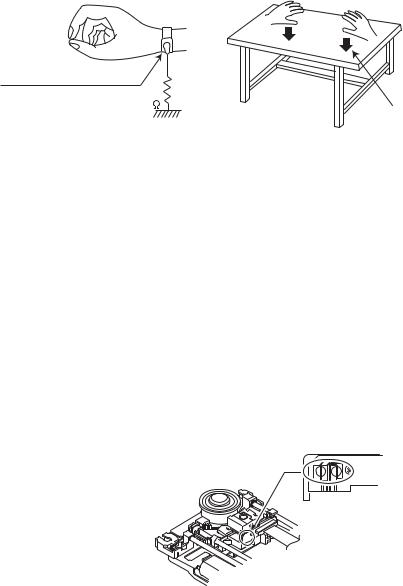
1.2.1Grounding to prevent damage by static electricity
Static electricity in the work area can destroy the optical pickup (laser diode) in devices such as laser products. Be careful to use proper grounding in the area where repairs are being performed.
(1)Ground the workbench
Ground the workbench by laying conductive material (such as a conductive sheet) or an iron plate over it before placing the traverse unit (optical pickup) on it.
(2)Ground yourself
Use an anti-static wrist strap to release any static electricity built up in your body.
(caption)
Anti-static wrist strap
1M
Conductive material (conductive sheet) or iron plate
(3)Handling the optical pickup
•In order to maintain quality during transport and before installation, both sides of the laser diode on the replacement optical pickup are shorted. After replacement, return the shorted parts to their original condition.
(Refer to the text.)
•Do not use a tester to check the condition of the laser diode in the optical pickup. The tester's internal power source can easily destroy the laser diode.
1.3Handling the traverse unit (optical pickup)
(1)Do not subject the traverse unit (optical pickup) to strong shocks, as it is a sensitive, complex unit.
(2)Cut off the shorted part of the flexible cable using nippers, etc. after replacing the optical pickup. For specific details, refer to the replacement procedure in the text. Remove the anti-static pin when replacing the traverse unit. Be careful not to take too long a time when attaching it to the connector.
(3)Handle the flexible cable carefully as it may break when subjected to strong force.
(4)It is not possible to adjust the semi-fixed resistor that adjusts the laser power. Do not turn it.
1.4Attention when traverse unit is decomposed
*Please refer to "Disassembly method" in the text for the pickup unit.
•Apply solder to the short land before the card wire is disconnected from the connector on the pickup unit. (If the card wire is disconnected without applying solder, the pickup may be destroyed by static electricity.)
•In the assembly, be sure to remove solder from the short land after connecting the card wire.
Solder short land section
1-4 (No.MB658<Rev.001>)

1.5Important for laser products
1.CLASS 1 LASER PRODUCT
2.CAUTION :
(For U.S.A.) Visible and/or invisible class II laser radiation when open. Do not stare into beam.
(Others) Visible and/or invisible class 1M laser radiation when open. Do not view directly with optical instruments.
3.CAUTION : Visible and/or invisible laser radiation when open and inter lock failed or defeated. Avoid direct exposure to beam.
4.CAUTION : This laser product uses visible and/or invisible laser radiation and is equipped with safety switches which prevent emission of radiation when the drawer is open and the safety interlocks have failed or are defeated. It is dangerous to defeat the safety switches.
5.CAUTION : If safety switches malfunction, the laser is able to function.
6.CAUTION : Use of controls, adjustments or performance of procedures other than those specified here in may result in hazardous radiation exposure.
! |
|
|
|
|
Please use enough caution not to |
|||||||||||||
|
|
|
|
|
|
see the beam directly or touch it |
||||||||||||
|
|
|
|
|
|
in case of an adjustment or operation |
||||||||||||
|
|
|
|
|
|
check. |
||||||||||||
|
|
|
|
|
|
|
|
|
|
|
|
|
|
|
|
|
|
|
|
|
|
|
|
|
|
|
|
|
|
|
|
|
|
|
|
|
|
|
|
|
|
|
|
|
|
|
|
|
|
|
|
|
|
|
|
|
|
|
|
|
|
|
|
|
|
|
|
|
|
|
|
|
|
|
|
|
|
|
|
|
|
|
|
|
|
|
|
|
|
|
|
|
|
|
|
|
|
|
|
|
|
|
|
|
|
|
|
|
|
|
|
|
|
|
|
|
|
|
|
|
|
|
|
|
|
|
|
|
|
|
|
|
|
|
|
|
|
|
|
|
|
|
|
|
|
|
|
|
|
|
|
|
|
|
|
|
|
|
|
|
|
|
|
|
|
|
|
|
|
|
|
|
|
|
|
|
|
|
|
|
|
|
|
|
|
|
|
|
|
|
|
|
|
|
|
|
|
|
|
|
|
|
|
|
|
|
|
|
|
|
|
|
|
|
|
|
|
|
|
|
|
|
|
|
|
|
|
|
|
|
|
|
|
|
|
|
|
|
|
|
|
|
|
|
|
|
|
|
|
|
|
|
|
|
|
|
|
|
|
|
|
|
|
|
|
|
|
|
|
|
|
|
|
|
|
|
|
|
|
|
|
|
|
|
REPRODUCTION AND POSITION OF LABELS and PRINT
WARNING LABEL and PRINT
(No.MB658<Rev.001>)1-5

SECTION 2
SPECIFIC SERVICE INSTRUCTIONS
This service manual does not describe SPECIFIC SERVICE INSTRUCTIONS.
SECTION 3
DISASSEMBLY
3.1Main body
3.1.1 Removing the Top cover (See Fig 1, 2)
(1)Remove the four screws A attaching the Top cover. (See Fig.1)
(2)Takeout two washers B and two washers C on the Top cover. (See Fig.2)
A
A
Fig.1
C
B
Fig.2
1-6 (No.MB658<Rev.001>)
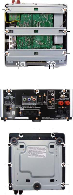
3.1.2 Removing the AL panel L and AL panel R (See Fig.3 to 5)
(1)Remove the two screws D and two screws E attaching the Bridge A. (See Fig.3)
(2)Remove the two screws F attaching the Bridge B. (See Fig.3)
(3)Remove the two screws G and three screws H attaching the bridge C. (See Fig.3, 4)
(4)Remove the two screws J attaching the AL panel L and AL panel R. (See Fig.3)
(5)Remove the two screws K and six screws L attaching the AL panel L and AL panel R. (See Fig.5)
G G
F F
E |
|
E |
J |
D |
J |
|
||
|
Fig.3 |
|
|
H |
|
Fig.4
K
L L
Fig.5
(No.MB658<Rev.001>)1-7
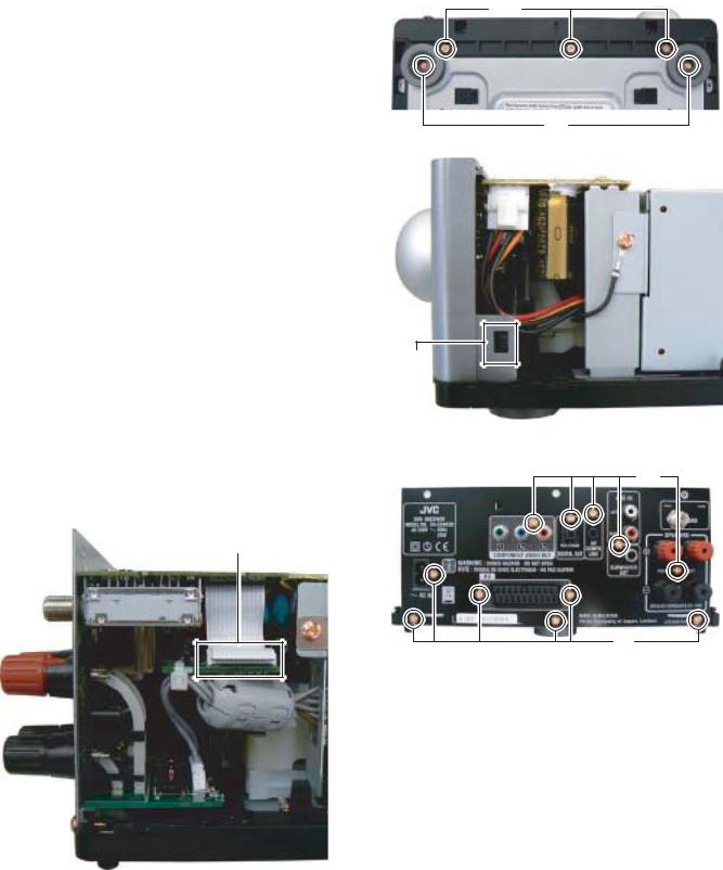
3.1.3 |
Removing the Front panel (See Fig.6, 7) |
N |
(1) |
Remove the two screws M attaching the Foot. (See Fig.6) |
(2)Remove the three screws N attaching the Foot. (See Fig.6)
(3)Disengage two hooks a engaged both side of the Front panel. (See Fig.7)
M
Fig.6
hook a
Fig.7
3.1.4 Removing the Rear panel (with DAB tuner pack) (See Fig.8, 9)
(1)Disconnect the card wire from DAB tuner pack connected to connector CN21 of the Micon board. (See Fig,8)
(2)Remove the eleven screws P attaching the Rear panel. (See Fig.9)
CN21
Fig.9
Fig.8
P
P
1-8 (No.MB658<Rev.001>)
Loading...