


 Loading...
ENGLISH
FRANÇAIS
ESPAÑOL/CASTELLANO
INSTRUCTIONS
DILA
PROJECTOR
DLARS66
DLARS56
DLARS48
DLARS46
For Customer use :
Enter below the serial No. which is located on the side of the cabinet. Retain this information for future reference.
Model No. DLA-RS66 / DLA-RS56 /
DLA-RS48 / DLA-RS46
Serial No.
Pour utilisation par le client :
Entrerci-dessous le N°de série qui est situé sous le boîtier. Garder cetteinformation comme référence pour le futur.
N° de modèle DLA-RS66 / DLA-RS56 / DLA-RS48 / DLA-RS46
N° de série
Instrucción para el cliente :
Introduzca a continuación el nº de serie que aparece en la parte inferior lateral de la caja. Conserve esta información como referencia para uso ulterior.
Modelo Nº DLA-RS66 / DLA-RS56 /
DLA-RS48 / DLA-RS46
Nº de serie
PC023482999
up Set Started Getting
Operate
Others Troubleshooting Maintenance Adjust/Set
Safety Precautions
Getting |
|
IMPORTANT INFORMATION |
|
|
|
Started |
|
This product has a High Intensity |
|
mercury. |
|
|
|
Dis-charge (HID) lamp that contains |
|
|
Disposal of these materials may be |
|
|
|
|
|
regulated in your community due to |
|
|
environmental considerations. For |
|
|
disposal or recycling information, |
|
|
please contact your local authorities or |
|
|
for USA, the Electronic Industries |
|
|
Alliance: http://www.eiae.org. |
|
|
|
|
|
WARNING: |
|
|
TO PREVENT FIRE OR SHOCK HAZARDS, DO |
|
|
NOT EXPOSE THIS APPLIANCE TO RAIN OR |
|
|
MOISTURE. |
|
|
|
|
|
WARNING: |
|
|
THIS APPARATUS MUST BE EARTHED. |
|
|
|
|
|
|
|
|
CAUTION: |
|
|
To reduce the risk of electric shock, do not remove |
|
|
cover. Refer servicing to qualified service personnel. |
|
|
|
|
|
This projector is equipped with a 3-blade grounding |
|
|
type plug to satisfy FCC rule. If you are unable to |
|
|
insert the plug into the outlet, contact your electrician. |
|
|
|
|
|
MACHINE NOISE INFORMATION |
|
|
(Germany only) |
|
|
Changes Machine Noise Information Ordinance 3. |
|
|
GSGV, January 18, 1991: The sound pressure level |
|
|
at the operator position is equal or less than 20 dB |
|
|
(A) according to ISO 7779. |
|
|
|
|
|
For the customers in Taiwan only |
|
|
|
FCC INFORMATION (U.S.A. only)
CAUTION:
Changes or modification not approved by JVC could void the user’s authority to operate the equipment.
NOTE:
This equipment has been tested and found to comply with the limits for Class B digital devices, pursuant to Part 15 of the FCC Rules. These limits are designed to provide reasonable protec tion against harmful interference in a residential installation. This equipment generates, uses, and can radiate radio frequency energy and, if not installed and used in accordance with the instruc tions, may cause harmful interference to radio communications. However, there is no guarantee that interference will not occur in a particular installation. If this equipment does cause harmful interference to radio or television reception, which can be determined by turning the equipment off and on, the user is encourage to try to correct the interference by one or more of the following measures:
 Reorient or relocate the receiving antenna.
 Increase the separation between the equipment and receiver.
 Connect the equipment into an outlet on a circuit different from that to which the receiver is connected.
 Consult the dealer or an experienced radio/TV technician for help.
Declaration of Conformity
Model Number : DLA-RS66U/DLA-RS56U/ DLA-RS48U/DLA-RS46U
Trade Name : JVC
Responsible party : JVC AMERICAS CORP. Address : 1700 Valley Road Wayne, N. J. 07470 Telephone Number : 973-317-5000
This device complies with Part 15 of FCC Rules. Operation is subject to the following two conditions:
(1) This device may not cause harmful interference, and (2) this device must accept any interference received, including interference that may cause undesired operation.
About the installation place
Do not install the projector in a place that cannot support its weight securely.
If the installation place is not sturdy enough, the projector could fall or overturn, possibly causing personal injury.
2
IMPORTANT SAFEGUARDS
Electrical energy can perform many useful functions. This unit has been engineered and manufactured to assure your personal safety. But IMPROPER USE CAN RESULT IN POTENTIAL ELECTRICAL SHOCK OR FIRE HAZARD. In order not to defeat the safeguards incorporated into this product, observe the following basic rules for its installation, use and service. Please read these Important Safeguards carefully before use.
- All the safety and operating instructions should be read before the product is operated.
- The safety and operating instructions should be retained for future reference.
- All warnings on the product and in the operating instructions should be adhered to.
- All operating instructions should be followed.
- Place the projector near a wall outlet where the plug can be easily unplugged.
- Unplug this product from the wall outlet before cleaning.
- Do not use liquid cleaners or aerosol cleaners. Use a damp cloth for cleaning.
- Do not use attachments not recommended by the product manufacturer as they may be hazardous.
- Do not use this product near water. Do not use immediately after moving from a low temperature to high temperature, as this causes condensation, which may result in fire, electric shock, or other hazards.
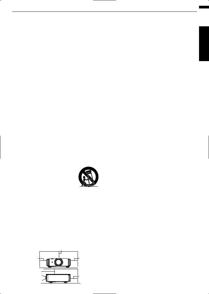
- Do not place this product on an unstable cart, stand, or table. The product may fall, causing serious injury to a child or adult, and serious damage to the product. The product should be mounted according to the manufacturer’s instructions, and should use a mount recommended by the manufacturer.
- When the product is used on a cart, care should be taken to avoid quick
stops, excessive force, and uneven surfaces which may cause the product and cart to overturn, damaging
equipment or causing possible injury to the operator.
-Slots and openings in the cabinet are provided for ventilation. These ensure reliable operation of the product and protect it from overheating. These openings must not be blocked or covered. (The openings should never be blocked by placing the product on bed, sofa, rug, or similar surface. It should not be placed in a built-in installation such as a bookcase or rack unless proper ventilation is provided and the manufacturer’s instructions have been adhered to.)
-To allow better heat dissipation, keep a clearance between this unit and its surrounding as shown below. When this unit is enclosed in a space of dimensions as shown below, use an air-conditioner so that the internal and external temperatures are the same. Overheating can cause
damage.
|
150 mm and above |
|
300 mm |
300 mm |
|
and above |
and above |
|
150 mm |
|
|
and above |
200 mm |
|
Front |
||
and above |
||
|
-Power source indicated on the label. If you are not sure of the type of power supply to your home, consult your product dealer or local power company.
-This product is equipped with a three-wire plug. This plug will fit only into a grounded power outlet. If you are unable to insert the plug into the outlet, contact your electrician to install the proper outlet. Do not defeat the safety purpose of the grounded plug.
-Power-supply cords should be routed so that they are not likely to be walked on or pinched by items placed upon or against them. Pay particular attention to cords at doors, plugs, receptacles, and the point where they exit from the product.
-For added protection of this product during a lightning storm, or when it is left unattended and unused for long periods of time, unplug it from the wall outlet and disconnect the cable system. This will prevent damage to the product due to lightning and power line surges.
-Do not overload wall outlets, extension cords, or convenience receptacles on other equipment as this can result in a risk of fire or electric shock.
-Never push objects of any kind into this product through openings as they may touch dangerous voltage points or short out parts that could result in a fire or electric shock. Never spill liquid of any kind on the product.
-Do not attempt to service this product yourself as opening or removing covers may expose you to dangerous voltages and other hazards. Refer all service to qualified service personnel.
-Unplug this product from the wall outlet and refer service to qualified service personnel under the following conditions:
a)When the power supply cord or plug is damaged.
b)If liquid has been spilled, or objects have fallen on the product.
c)If the product has been exposed to rain or water.
d)If the product does not operate normally by following the operating instructions. Adjust only those controls that are covered by the Operation Manual, as an improper adjustment of controls may result in damage and will often require extensive work by a qualified technician to restore the product to normal operation.
e)If the product has been dropped or damaged in any way.
f)When the product exhibits a distinct change in performance, this indicates a need for service.
-When replacement parts are required, be sure the service technician has used replacement parts specified by the manufacturer or with same characteristics as the original part. Unauthorized substitutions may result in fire, electric shock, or other hazards.
-Upon completion of any service or repairs to this product, ask the service technician to perform safety checks to determine that the product is in proper operating condition.
-The product should be placed more than one foot away from heat sources such as radiators, heat registers, stoves, and other products (including amplifiers) that produce heat.
-When connecting other products such as VCR’s, and DVD players, you should turn off the power of this product for protection against electric shock.
3
Started Getting

Started Getting
-Do not place combustibles behind the cooling fan. For example, cloth, paper, matches, aerosol cans or gas lighters that present special hazards when over heated.
-Do not look into the projection lens while the illumination lamp is turned on. Exposure of your eyes to the strong light can result in impaired eyesight.
-Do not look into the inside of this unit through vents (ventilation holes), etc. Do not look at the illumination lamp directly by opening the cabinet while the illumination lamp is turned on. The illumination lamp also contains ultraviolet rays and the light is so powerful that your eyesight can be impaired.
-Do not drop, hit, or damage the light-source lamp (lamp unit) in any way. It may cause the light-source lamp to break and lead to injuries. Do not use a damaged light source lamp. If the light-source lamp is broken, ask your dealer to repair it. Fragments from a broken light-source lamp may cause injuries.
-The light-source lamp used in this projector is a high pressure mercury lamp. Be careful when disposing of the light-source lamp. If anything is unclear, please consult your dealer.
-Do not ceiling-mount the projector to a place which tends to vibrate; otherwise, the attaching fixture of the projector could be broken by the vibration, possibly causing it to fall or overturn, which could lead to personal injury.
-Use only the accessory cord designed for this product to prevent shock.
-For health reasons, please take a break of about 5-15 minutes every 30-60 minutes and let your eyes rest. Please refrain from watching any 3D-images when you feel tired, unwell or if you feel any other discomfort. Moreover, in case you see a double image, please adjust the equipment and software for proper display. Please stop using the unit if the double image is still visible after adjustment.
-Once every three years, please perform an internal test. This unit is provided with replacement parts needed to maintain its function (such as cooling fans). Estimated replacement time of parts can vary greatly depending on frequency of use and the respective environment. For replacement, please consult your dealer, or the nearest authorized JVC service center.
-When fixing the unit to the ceiling, Please note that we do not take any responsibility, even during the warranty period, if the product is damaged due to use of metal fixtures used for fixation to the ceiling other than our own or if the installation environment of said metal fixtures is not appropriate. If the unit is suspended from the ceiling during use, please be careful in regard to the ambient temperature of the unit. If you use a central heating, the temperature close to the ceiling will be higher than normally expected.
-Video images can burn into the electronic com ponent parts. Please do not display screens with still images of high brightness or high contrast, such as found in video games and computer programs. Over a long period of time it might stick to the picture element. There is no problem with the playback of moving images, e.g. normal video footage.
-Video images can burn into the electronic com ponent parts. Please do not display screens with still images of high brightness or high contrast, such as found in video games and computer programs. Over a long period of time it might stick to the picture element. There is no problem with the playback of moving images, e.g. normal video footage.
-Not using the unit for a long time can lead to malfunction. Please power it on and let it run occasionally. Please avoid using the unit in a room where cigarettes are smoked. It is impos sible to clean optical component parts if they are contaminated by nicotine or tar. This might lead to performance degradation.
-Please watch from a distance three times the height of the projected image size. Persons with photosensitivity, any kind of heart disease, or weak health should not use 3D glasses.
-Watching 3D-images might be cause of illness. If you feel any change in your physical condition, please stop watching immediately and consult a physician if necessary.
-When watching 3D images, it is recommended to take regular breaks. As the length and frequency of the required breaks differ for every person, please judge according to your own condition.
-If your child watches while wearing 3D glasses, it should be accompanied by its parents or an adult guardian. The adult guardian should be careful to avoid situations where the child’s eyes might become tired, as responses to tiredness and discomfort, etc., are hard to detect, and it is possible for the physical condition to deteriorate very quickly. As the visual sense is not yet fully developed in children under the age of 6, please consult a physician in regard to any problem concerning 3D-images if necessary.
-Note that when using the 3D feature, the video output may appear different from the original video image due to image conversion on the device.
* DO NOT allow any unqualified person to install the unit.
Be sure to ask your dealer to install the unit (e.g.attaching it to the ceiling) since special technical knowledge and skills are required for installation. If installation is performed by an unqualified person, it may cause personal injury or electrical shock.
4
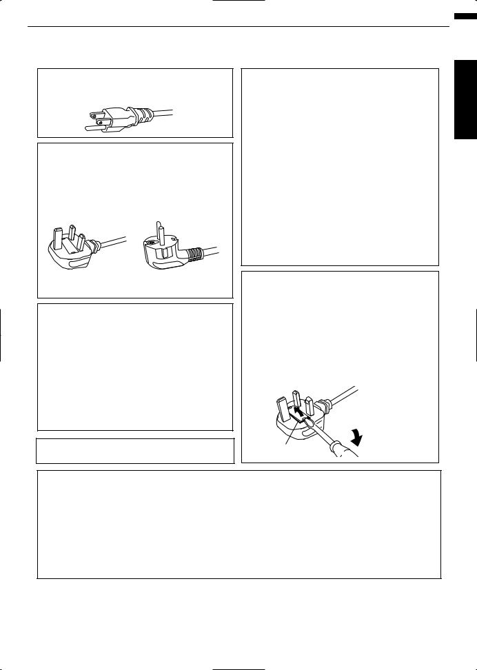
POWER CONNECTION
For USA and Canada only
Use only the following power cord.
Power cord
The power supply voltage rating of this product is AC110V – AC240V. Use only the power cord designated by our dealer to ensure Safety and EMC. Ensure that the power cable used for the projector is the correct type for the AC outlet in your country. Consult your product dealer.
Power cord
For United Kingdom |
For European continent |
|
countries |
WARNING:
Do not cut off the main plug from this equipment.
If the plug fitted is not suitable for the power points in your home or the cable is too short to reach a power point, then obtain an appropriate safety approved extension lead or adapter or consult your dealer. If nonetheless the mains plug is cut off, dispose of the plug immediately, to avoid a possible shock hazard by inadvertent connection to the main supply. If a new main plug has to be fitted, then follow the instruction given below.
WARNING:
THIS APPARATUS MUST BE EARTHED.
IMPORTANT (Europe only):
The wires in the mains lead on this product are colored Vert et jaune in accordance with the following cord:
Green-and-yellow : Earth
Blue |
: Neutral |
Brown |
: Live |
As these colors may not correspond with the colored making identifying the terminals in your plug, proceed as follows:
The wire which is colored green-and-yellow must be connected to the terminal which is marked M with the letter E or the safety earth or colored green or green-and-yellow. The wire which is colored blue must be connected to the terminal which is marked with the letter N or colored black.
The wire which is colored brown must be connected to the terminal which is marked with the letter L or colored red.
POWER CONNECTION (United Kingdom only)
IMPORTANT (Europe only):
When replacing the fuse, be sure to use only a correctly rated approved type, re-fit the fuse cover.
IF IN DOUBT —— CONSULT A COMPETENT ELECTRICIAN.
Open the fuse compartment with the blade screwdriver, and replace the fuse.
(* An example is shown in the illustration below.)
Fuse
Dear Customer,
This apparatus is in conformance with the valid European directives and standards regarding electromagnetic compatibility and electrical safety.
European representative of JVC KENWOOD Corporation is: JVC Technical Services Europe GmbH
Postfach 10 05 04
61145 Friedberg Germany
Started Getting
5
Started Getting
ENGLISH
Information for Users on Disposal of Old Equipment and Batteries
Battery
Products
[European Union only]
These symbols indicate that equipment with these symbols should not be disposed of as general household waste. If you want to dispose of the product or battery, please consider the collection systems or fa cilities for appr opriate recycling.
Notice: The sign Pb below the symbol for batteries indicates that this battery contains lead.
DEUTSCH
Benutzerinformationen zur Entsorgung alter Geräte und Batterien
|
|
|
[Nur Europäische Union] |
|
|
|
|
Diese Symbole zeigen an, dass derartig gekennzeichnete Geräte nicht als normaler |
|
|
|
|
Haushaltsabfall entsorgt werden dürfen. We nden Sie sich zur Entsorgung des |
|
|
|
|
Produkts oder der Batterie an die hierfür vorgesehenen Sammelstellen oder |
|
|
|
Batterie |
Einrichtungen, damit eine fachgerechte Wiederverwertung möglich ist. |
|
|
|
Hinweis: Das Zeichen Pb unterhalb des Batteriesymbols gibt an, dass diese |
||
|
|
|||
Produkte |
Batterie Blei enthält. |
|||
|
|
|
|
|
|
|
|
|
FRANÇAIS |
Informations relatives à l’élimination des appareils et des piles usagés, à l’intention des utilisateurs
|
|
|
[Union européenne seulement] |
|
|
|
|
Si ces symboles figurent sur les produits, cela signifie qu’ils ne doivent pas être |
|
|
|
|
jetés comme déchets ménagers. Si vous voulez jeter ce produit ou cette pile, |
|
|
|
|
veuillez considérer le système de collection de déc hets ou les centres de |
|
|
|
Pile |
recyclage appropriés. |
|
|
|
Notification: La marque Pb en dessous du symbole des piles indique que cette |
||
Produits |
pile contient du plomb. |
|||
|
|
|
|
|
|
|
|
|
NEDERLANDS |
Informatie voor gebruikers over het verwijderen van oude apparatuur en batterijen
|
|
|
[Alleen Europese Unie] |
|
|
|
|
Deze symbolen geven aan dat appara tuur met dit symbool niet mag worden |
|
|
|
|
weggegooid als algemeen huishoudelijk afval. Als u het product of de batterij wilt |
|
|
|
|
weggooien, kun t u inzamelsystemen of faciliteiten voor een geschikte recycling |
|
|
|
Batterij |
gebruiken. |
|
|
|
Opmerking: Het teken Pb onder het batterijsymboo l geeft aan dat deze batterij |
||
|
|
|||
|
Producten |
|
lood bevat. |
|
|
|
|
|
|
|
|
|
|
ESPAÑOL / CASTELLANO |
Información para los usuarios sobre la eliminación de baterías/pilas usadas
[Sólo Unión Europea]
Estos símbolos indican que el equipo con estos símbolos no debe desecharse con la basura doméstica. Si desea desechar el pro ducto o batería/pila, acuda a los sistemas o centros de recogida para que los reciclen debidamente.
Baterías/pilas Atención: La indicación Pb debajo del símbolo de batería/pila indica que ésta contiene plomo.
Productos
6
ITALIANO
Informazioni per gli utenti sullo smaltimento delle apparecchiature e batterie obsolete
|
|
|
[Solo per l’Unione Europea] |
|
|
|
|
Questi simboli indicano che le apparecchiature a cui sono relativi non devono |
|
|
|
|
essere smaltite tra i rifiuti domestici generici. Se si desidera smaltire questo |
|
|
|
|
prodotto o questa batteria, prendere in considerazione i sistem i o le strutture di |
|
|
|
Batteria |
raccolta appropriati per il riciclaggio corretto. |
|
|
|
Nota: Il simbolo Pb sotto il simbolo delle batter ie indica che questa batteria contiene |
||
Prodotti |
piombo. |
|||
|
|
|
|
|
|
|
|
|
PORTUGUÊS |
Informação para os utilizadores acerca da eliminação de equipamento usado e pilhas
|
|
|
[Apenas União Europeia] |
|
|
|
|
Estes símbolos indicam que o equipamento com estes símbolos não deve ser |
|
|
|
|
eliminado juntamente com o restante lixo doméstico. Se p retende eliminar |
|
|
|
|
o produto ou a pilha, utilize os sistemas de recolha ou instalações para uma |
|
|
|
Pilha |
reciclagem apropriada. |
|
|
|
Aviso: O sinal Pb abaixo do símbolo para pilhas indica que esta pilha contém |
||
Produtos |
chumbo. |
|||
|
|
|
|
|
|
|
|
|
ΕΛΛΗΝΙΚΑ |
Πληροφορίες για την απόρριψη παλαιού εξοπλισμού και μπαταριών
|
|
|
[ Ευρωπαϊκή Ένωση μόνο ] |
|
|
|
|
Αυτά τα σύμβολα υποδηλώνουν ότι ο εξοπλισμός που τα φέρει δεν θα πρέπει |
|
|
|
|
να απορριφθεί ως κοινό οικιακό απόρριμμα . Εάν επιθυμείτε την απόρριψη |
|
|
|
|
αυτού του προϊόντος ή αυτής της μπαταρίας , χρησιμοποιήστε το σύστημα |
|
|
|
Μπαταρία |
περισυλλογής ή εγκαταστάσεις για ανάλογη ανακύκλωση . |
|
|
|
Σημείωση: Το σύμβολο Pb κάτω από το σύμβολο μπαταρίας υποδηλώνει ότι |
||
Προϊόντα |
η μπαταρία περιέχει μόλυβδο . |
|||
|
|
|
|
|
|
|
|
|
DANSK |
Brugerinformation om bortskaffelse af gammelt udstyr og batterier
|
|
|
[Kun EU] |
|
|
|
|
Disse symboler angiver, at udstyr med disse symboler ikke må bortskaffes som |
|
|
|
|
almindeligt husholdningsaffald. Hvis du ønsker at smide dette produkt eller batteri |
|
|
|
|
ud, bedes du overveje at bruge indsamlingssystem et eller steder, hvor der kan |
|
|
|
Batteri |
ske korrekt gen brug. |
|
|
|
Bemærk: Tegnet Pb under symbolet for batterierne angiver, at dette batteri |
||
|
|
|||
|
Produkter |
|
indeholder bly. |
|
|
|
|
|
|
|
|
|
|
SUOMI |
Tietoja vanhojen laitteiden ja akkujen hävittämisestä
[Vain Euroopan unioni]
Nämä symbolit ilmaisevat, että symboleilla merk ittyä laitetta ei tulisi hävittää tavallisen kotitalousjätteen mukana. Jos haluat hävit tää tuotteen tai sen akun, tee se hyödyntämällä akkujen keräyspisteitä tai muita kier rätyspaikkoja.
Akku
Huomautus: Akkusymbolin alapuolella oleva Pb-merk intä tarkoit taa, että akku sisältää lyijyä.
Tuotteet
Started Getting
7
Started Getting
SVENSKA
Information för användare gällande bortskaffning av gammal utrustning och batterier
Batteri
Produkter
[Endast den Europeiska unionen]
Dessa symboler indikerar att utrustning med dessa symboler inte ska hanteras som vanligt hushållsavfall. Om du vill bortsk affa produkten eller batteriet ska du använda uppsamlingssystem eller inrättningar för lämplig återvinning.
Observera: Märkningen Pb under symbolen för batterier indikerar att detta batteri innehåller bly.
NORSK
Opplysninger til brukere om kassering av gammelt utstyr og batterier
Batteri
Produkter
[Bare EU]
Disse symbolene viser at utstyr med dette symbolet, ikke skal kastes sammen med vanlig husholdningsavfall. Hvis du vil kass ere dette produkte t eller batteriet, skal du vurdere å bruke innsam lingssystemene eller andre muligheter for riktig gjenbruk.
Merk: Tegnet Pb under symbolet for batterie r, viser at batteriet inneholder bly.
Сведения для пользователей по утилизации старого оборудования и батарей
|
|
[только для Европейского союза] |
|
|
|
Данные символы указывают на то, что оборудование, на которое они |
|
|
|
нанесены, не должны утилизироваться, как обычные бытовые отходы. При |
|
|
|
необходимости утилизировать такое изделие или батарею обратитесь в |
|
|
Батарея |
специальный пункт сбора для их надлежащей переработки. |
|
|
Уведомление: Надпись Pb под символом батар ей указывает на то, что |
||
Изделия |
данная батарея содержит свинец. |
||
|
|
|
|
|
|
|
|
Informace pro uživatele k likvid aci starého zařízení a baterií
[Pouze Evropská unie]
Tyto symboly označují, že produkty s těmito symboly se nesmí likvidovat jako běžný odpad. Pokud chcete produkt nebo baterii zlikvidovat, využijte sběrný systém nebo jiné zařízení, které zaji stí řádnou recyklaci.
|
|
Baterie |
Bemærk: Značka Pb pod symbolem pro ba te rie znamená, že tato baterie |
|
|
Produkty |
|
obsahuje olovo. |
|
|
|
|
|
|
|
|
|
|
POLSKI |
Informacje dla użytkowników dotyczące poz bywania się zużytego sprzętu i baterii
|
|
[Tylko kraje Unii Europejskiej] |
|
|
Te symbole oznaczają, że sprzę tu nie należy wyr zucać razem z odpadami |
|
|
gospodarczymi. Jeśli trzeba po zbyć się tego produktu lub ba terii, proszę |
|
|
skorzystać z systemu odbioru lub urządzeń do zbió rki odpadów elektronicznych, |
|
Bateria |
w celu odpowiedniego ponowne go ich przetworzenia. |
|
Uwaga: Oznaczenie Pb, znajdujące się pod symbole m baterii wskazuje, że ta |
|
|
||
Produkty |
bateria zawiera ołów. |
|
8
MAGYAR
Felhasználói információ az elhasznált be rendezések és akkumulátorok elhelyezéséről
|
|
|
[Csak az Európai Unióban] |
|
|
|
|
Ez a szimbólum azt jelzi, hogy a berendezés nem helyezhető az általános |
|
|
|
|
háztartási hulladék közé. Ha meg szeretne szabadulni a terméktől vagy az |
|
|
|
|
akkumulátortól, akkor legyen tekintettel az gyűjtő rendszerre vagy intézményekre |
|
|
|
Akkumulátor |
a megfelelő hasznosítás érdekében. |
|
|
|
Megjegyzés: Az alábbi Pb szimbólum - ha az akkum ulátoron megtalálható - azt |
||
Termékek |
jelzi, hogy az akkumulátor ólmot tartalmaz. |
|||
|
|
|
|
|
|
|
|
|
|
|
|
|
|
Cрпска |
Informacije za korisnike o odlaganju stare opreme i baterija
|
|
[Samo u zemljama gde se primenjuje] |
|
|
Ovi simboli ukazuju da proizvod i baterije sa ovim simbolom ne smeju biti odloženi |
|
|
kao nesortiran kućni otpad. Ako želite da ih se rešite, molimo vas da ne |
|
|
upotrebljavate običnu kantu za đubre. Postoje zasebni sistemi za prikupljanje |
|
Baterija |
ovakvih proizvoda. |
|
Naznaka: Hemijski simbol Pb ispod simbola za baterije ukazuje na to da li baterija |
|
Produkt |
sadrži olovo. |
|
Started Getting
9

|
Contents |
|
Getting |
|
|
|
Getting Started |
|
|
Safety Precautions .................................................. |
2 |
|
Accessories/Optional Accessories ........................ |
11 |
Started |
|
|
|
Check the Accessories ...................................... |
11 |
|
Optional Accessories ......................................... |
11 |
|
Main Features ....................................................... |
12 |
|
Controls and Features ........................................... |
14 |
|
Main Unit Front ................................................ |
14 |
|
Main Unit Bottom ............................................. |
14 |
|
Main Unit Rear ................................................. |
15 |
|
Main Unit Input Terminals ................................ |
16 |
|
Remote Control ................................................. |
17 |
|
Loading Batteries into the Remote Control ........ |
18 |
|
Effective Range of Remote Control Unit ............ |
18 |
|
Set up |
|
|
Installing the Projector ........................................... |
19 |
|
Precautions during Installation ........................... |
19 |
|
Precautions during Mounting ............................. |
20 |
|
Adjusting the Position ........................................ |
21 |
|
Connecting the Projector ....................................... |
22 |
|
Connecting to the HDMI Input Terminal (Digital |
|
|
Input) ................................................................. |
22 |
|
Connecting to the Component Video Input Terminal |
|
|
(Analog Input) .................................................... |
23 |
|
Connecting to the PC Input Terminal ...... |
23 |
|
Connecting to the LAN Terminal ........................ |
24 |
|
Connecting to the RS232C Terminal ................ |
24 |
|
Connecting to the REMOTE Terminal ............... |
24 |
|
Connecting to the TRIGGER Terminal ............... |
25 |
|
Connecting the Power Cord (Supplied Accessory) ...... |
25 |
|
Operate |
|
|
Viewing Videos ...................................................... |
26 |
|
Adjusting the Projector Screen .............................. |
28 |
|
Adjusting the Lens According to the Projection |
|
|
Position .............................................................. |
28 |
|
Saving and Retrieving Adjustment Settings ....... |
29 |
|
Adjusting Image Quality Automatically According to |
|
|
the Viewing Environment ............ |
31 |
|
Setting Screen Correction .................................. |
32 |
|
Adjusting the Screen Size (Aspect) ................... |
33 |
|
Viewing 3D Movies ................................................ |
34 |
|
Installing the 3D SYNCHRO EMITTER .............. |
34 |
|
Viewing 3D Movies ............................................ |
35 |
|
Converting 2D Movies to 3D Movies for Viewing ....... |
35 |
|
Adjusting 3D Movies .......................................... |
36 |
|
Adjust/Set |
|
|
Selecting an Image Quality According to the Video |
|
|
Type ...................................................................... |
37 |
|
Setting the Picture Mode ................................... |
37 |
Setting the Color Profile ............. |
38 |
Adjusting Movies for Increased Expressiveness |
|
(Multiple Pixel Control) ................... |
40 |
Finetuning the Image Quality ............................... |
41 |
Adjusting the Output Value of the Projected Image |
|
(Gamma) ........................................................... |
41 |
Adjusting to the Preferred Gamma Setting (Custom |
|
Gamma) ............................................................ |
43 |
Compensating Highlights and Shadows (Dark/ |
|
Bright Level) ...................................................... |
44 |
Adjusting to the Preferred Color (Color |
|
Management) .................................................... |
45 |
Reducing the Afterimage of Fastmoving Images |
|
(Clear Motion Drive (C.M.D.)) ............................ |
46 |
Adjustments and Settings in the Menu .................. |
47 |
LIst of Menu Items ............................................. |
47 |
Picture Adjust .................................................... |
49 |
Input Signal ........................................................ |
53 |
Installation ......................................................... |
55 |
Display Setup .................................................... |
61 |
Function ............................................................. |
62 |
Information ......................................................... |
64 |
Maintenance |
|
Replacing the Lamp .............................................. |
65 |
Lamp Replacement Procedure .......................... |
65 |
Resetting the Lamp Time ................................... |
67 |
Maintaining the Cabinet and Remote Control ........ |
67 |
Cleaning and Replacing the Filter ......................... |
68 |
Troubleshooting |
|
Troubleshooting .................................................... |
69 |
When the following messages appear... ................ |
71 |
Others |
|
External Control .................................................... |
72 |
RS232C Specifications ..................................... |
72 |
TCP/IP Connection ............................................ |
72 |
Command Format .............................................. |
73 |
Remote Control Code ........................................ |
74 |
Communications Example ................................. |
75 |
Specifications ........................................................ |
76 |
Index ..................................................................... |
84 |
Symbols used in this manual
indicates a function that is supported by DLARS66.indicates a function that is supported by DLARS56.indicates a function that is supported by DLARS48.indicates a function that is supported by DLARS46.
Items not marked with any of the above symbols are supported by all models.
10
Accessories/Optional Accessories
Check the Accessories
Lens cover .............................................................. |
1 piece |
*It is attached to the main unit at the time of shipment. |
|
Remote control ....................................................................... |
1 piece |
AAAsize batteries (for operational check) ............................ |
2 pieces |
Power cord (for USA) (about. 2 m) ......................................... |
1 piece |
Power cord (for UK) (about. 2 m) ............................................ |
1 piece |
Power cord (for EU) (about. 2 m) ............................................ |
1 piece |
INSTRUCTIONS (this book), warranty card, and other printed material are also included.
Optional Accessories
Replacement lamp model: PKL2312U
3D GLASSES models: PKAG2, PKAG3
3D SYNCHRO EMITTER: models PKEM1, PKEM2
Compatibility Chart for 3D SYNCHRO EMITTER and 3D GLASSES
|
|
|
3D GLASSES |
|
|
|
PKAG1 * |
PKAG2 |
PKAG3 |
|
(Communication |
(Communication |
(Communication |
|
|
|
Method: IR (Infrared)) |
Method: IR (Infrared)) |
Method: RF (Radio |
|
|
|
|
frequency)) |
3D SYNCHRO EMITTER |
PKEM1 |
X |
X |
— |
|
(Communication |
|
|
|
|
Method: IR (Infrared)) |
|
|
|
|
PKEM2 |
— |
— |
X |
|
(Communication |
|
|
|
|
Method: RF (Radio |
|
|
|
|
frequency)) |
|
|
|
* Discontinued product |
|
|
|
|
Please check with your authorized dealer for details. |
|
|
||
Started Getting
11
Main Features
Started Getting
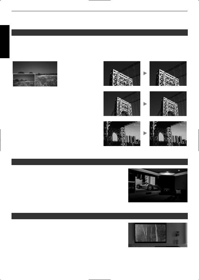
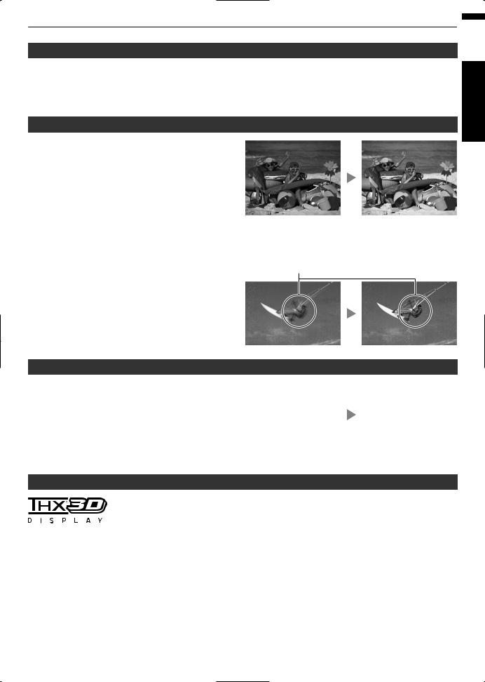
Highdefinition 4K display that surpasses full HD quality
The optical engine equipped with a new eshift2 device has achieved a resolution of 4K.
With JVC’s newlydeveloped imageprocessing algorithm, you can now enjoy the enhanced expressiveness of the 4K quality. (p. 40)
Original |
JVC’s Image Technol- |
|
ogy |
4K
3840×2160
Full HD 1920×1080
Delivers a clearer expression with the jaggedness and blurriness of the oblique lines reduced
Contrast is enhanced even for the details for them to be reproduced realistically
Noise is reduced to produce vivid and crisp images
The photos are for illustrative purposes only.
3D video expressions with a highly realistic feel
With the 3D feature, you can enjoy 3D movies with a more realistic effect. (p. 34)
With the 2D3D conversion feature, you can now enjoy 3D movies by converting 2D videos of TV programs or those that are recorded using a home video camera into 3D ones. (p. 35)
The photos are for illustrative purposes only.
Optimal image quality adjustment according to the viewing environment
Halation that occurs in environments such as a living room with white walls is taken into consideration for optimal viewing. (p. 31)
For , you can utilize the optional optical sensor and dedicated software to make finer adjustments.
For more details, please refer to our website.
http://www3.jvckenwood.com/projector/support/index.html
12
Flexible installation
In addition to the 2x motorized zoom & focus lens, the wide coverage of the lens shift functions also makes installation of the projector more flexible. (p. 28)
The lens memory feature, which enables focus, zoom, or shift settings to be saved or retrieved, enables you to switch to different video size formats easily.
Customizable image quality adjustment feature
You can make adjustments according to the type of video images or your preferences to enjoy the videos in optimal quality. (p. 37)
adopts the Real Color Imaging Technology
(a color reproduction technology developed by JVC) to enable reproduction in an image quality that is closer to the original image. (p. 38)
|
The photos are for illustrative purposes only. |
Clear video expression with little afterimage (C.M.D.) |
|
By employing the highdefinition image interpolation |
Sharp depiction of details with minimal blur |
technology developed by JVC, you can enjoy videos with fast movements, such as sports, in a sharp quality.
(p. 46)
* C.M.D. is the abbreviation for Clear Motion Drive.
The photos are for illustrative purposes only.
Highprecision pixel adjustment feature
With the highlyprecise “Pixel Adjust” feature, you can |
|
|
|
|
|
|
|
enjoy a clear video quality with little color fringing |
ABCD |
|
ABCD |
throughout the entire image. |
|
||
(p. 55 )(p. 56 ) |
|
||
* The accuracy level that can be adjusted varies according |
|
||
to the model. |
|
|
|
|
Before adjustment |
|
After adjustment |
The photos are for illustrative purposes only.
THX certification
For , a “THX 3D Display Certification” by THX has been obtained.
In addition to 2D movies, you can also enjoy faithful reproduction of images in a “quality as intended by the filmmaker” during playback of 3D movies.
The THX 3D certification is “an indication of high definition and high resolution”, which is granted to products that have cleared more than 400 image quality tests.
Started Getting
13
Controls and Features
Started Getting
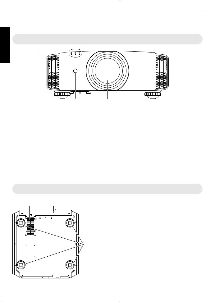
Main Unit Front
D
E


 E
E
C |
AB |
A Lens
This is a projection lens. Do not look through the lens while an image is projected.
B Lens cover
The lens cover opens/closes when the power supply is turned on/off. (p. 55)
For , attach the lens cover when the unit is not in use.
C Remote Sensor (front)
Please aim the remote control at this area when using it.
* There is also a remote sensor at the rear.
Main Unit Bottom
D Indicator
Refer to “Indicator Display on the Main Unit” (p. 81).
E Exhaust vent
Warm air is discharged to cool down the internal temperature.
Do not block the vents.
F |
G |
F Inlets (at 3 points on the rear/bottom)
The inlets take in air to cool down the internal temperature.
Do not block or prevent the outflow of hot air. Doing so may cause the unit to malfunction.
* There are two inlets on the right and left sides at the rear of the unit.
G Manual button for lens cover
The lens cover can be opened when pressed down.
HIt is used for maintenance purposes. You can also make use of it when you need to open the lens cover urgently.
H Feet
The height and angle of the projector can be adjusted by turning the foot. (0 to 5 mm) (p. 21)
When the foot is removed, it can be used as the mounting holes for the ceiling mount bracket.
14

Main Unit Rear
F


 F
F 


 J
J
I M L K
I Input terminals
In addition to the video input terminal, there are also other connection terminals for devices such as controllers and optional equipment. are
used in the illustration.
Please see “Main Unit Input Terminals”p. 16 for more details about the terminals and .
L Remote Sensor (rear)
Please aim the remote control at this area when using it.
* There is also a remote sensor at the front.
M Power input terminal
Connect the supplied power cord to this terminal.
J Lamp cover
When replacing the light source lamp, remove this cover.
K Operation panel
For more details, please refer to the “Operation panel” in the diagram below.
Operation panel

 A [STANDBY/ON]: Turns “on”/“off” the
power
 [INPUT]: Switches the input
 [OK]: Confirms a selection
Started Getting

 [JKH I] keys: Selects an item
[MENU]: Displays the menu |
[BACK]: Returns to the previous menu |
15
Started Getting
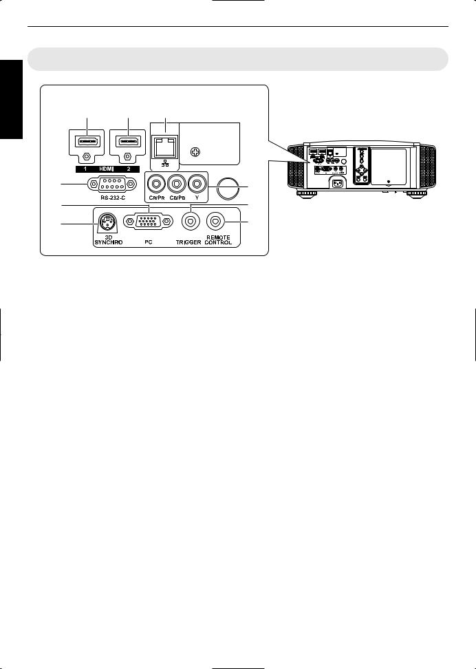
Main Unit Input Terminals
Enlarged View of Rear Face
A B C
|
D |
G |
|
E |
H |
|
F |
I |
|
|
|
A [HDMI 1] input terminal |
G Component video input terminals |
|
B |
[HDMI 2] input terminal |
(RCA x 3) |
|
For connecting to devices that support component |
|
For connecting to devices that support HDMI output. |
signal output. |
|
(p. 22) |
It can be used as an input terminal for analog RGB (G |
|
It is fitted to the M3 lock hole. The depth of the screw |
on Sync), component (Y, Cb, Cr), or DTV format (Y, |
|
hole is 3 mm. |
Pb, Pr) signals. |
|
C [LAN] terminal (RJ45)
The projector can be controlled by connecting it to a PC through the computer network for control commands to be sent to the projector.
D [RS232C] terminal (Dsub 9pin male)
The projector can be controlled by connecting a PC to this terminal.
*The LAN and RS232C terminals cannot be used at the same time. (p. 62)
E[PC] Input terminal (Dsub 15pin)
This is an input terminal used for PC signals (RGB video signals and sync signals) only.
It can be connected to a PC monitor output terminal, etc.
H [TRIGGER] terminal ( )
Output terminal for DC 12V, 100 mA power supply. It is used for sending output signals to control elevating screens for which the use of a SCREEN TRIGGER is supported.
Note that improper connection may damage the projector. (Tip=DC +12 V, Sleeve=GND)
I [REMOTE] terminal (stereo mini jack)
Use this terminal when a remote control unit is not usable, such as when the projector is installed in a dedicated box or for rear projection.
Connect an external remote sensor unit to the projector unit.
For details on the external infrared sensor and connecting cable, please contact your dealer.
F [3D SYNCHRO] terminal
By connecting a 3D SYNCHRO EMITTER (sold separately) to this terminal, you can view 3D movies.
16
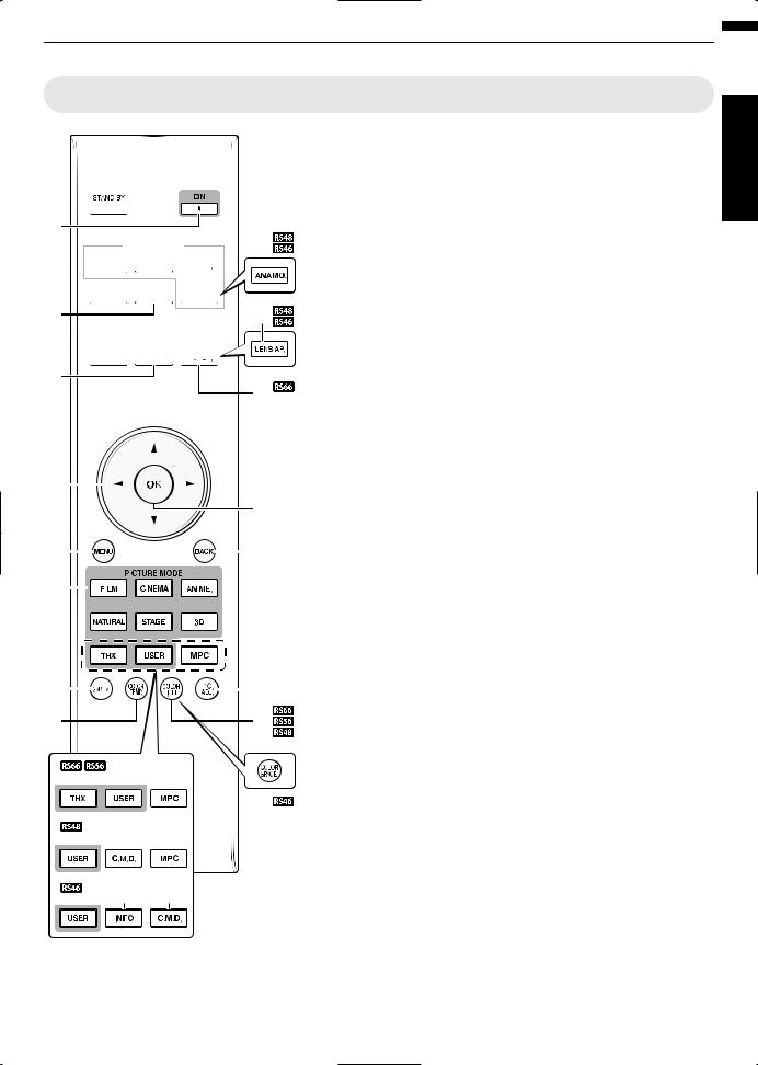
Remote Control
A B [STAND BY]
A

B
 F C
F C


D


E J
G


H
I K
K

 L
L
Turns off the power. (p. 27)
B C [ON]
Turns on the power. (p. 26)
C [INPUT]
Select an input from [HDMI 1], [HDMI 2], [COMP.], and [PC] ( only). (p. 26)
D [3D FORMAT]
Switches the 3D format. (p. 35)
E [3D SETTING]
Displays the 3D setting menu. (p. 35)
F [ANAMO.]
|
|
|
|
|
|
|
|
|
|
|
|
|
|
|
|
|
|
|
|
|
|
Switches the anamorphic |
|
|
|
|
|
|
|
|
|
|
|
|
|
|
|
|
|
|
|
|
|
|
mode. (p. 57) |
M |
|
|
|
|
|
|
|
|
|
|
|
|
|
|
|
G [LENS CONTROL] |
||||||
|
|
|
|
|
|
|
|
|
|
|
|
|
||||||||||
|
|
|
|
|
|
|
|
|
|
|
|
|
|
|
|
|
|
|
|
N |
For adjusting focus, zoom, and |
|
|
|
|
|
|
|
|
|
|
|
|
|
|
|
|
|
|
|
|
|
|
|
shift. (p. 28) |
O |
|
|
|
|
|
|
|
|
|
|
|
|
|
|
|
|
P |
H [LENS MEMORY] |
||||
|
|
|
|
|
|
|
|
|
|
|
|
|
|
|
|
|
|
|
|
|
|
Switches between saving, |
Q |
|
|
|
|
|
|
|
|
|
|
|
|
|
|
|
|
|
|
|
|
|
retrieving, and editing of the |
|
|
|
|
|
|
|
|
|
|
|
|
|
|
|
|
|
|
|
|
|
||
|
|
|
|
|
|
|
|
|
|
|
|
|
|
|
|
|
|
|
|
lens memory. (p. 29) |
||
|
|
|
|
|
|
|
|
|
|
|
|
|
|
|
|
|
||||||
|
|
|
|
|
|
|
|
|
|
|
|
|
|
|
|
|
|
|
|
|
|
|
|
|
|
|
|
|
|
|
|
|
|
|
|
|
|
|
|
|
|
|
|
|
I [C.M.D.] |
|
|
|
|
|
|
|
|
|
|
|
|
|
|
|
|
|
|
|
|
|
|
For setting frame interpolation. |
|
|
|
|
|
|
|
|
|
|
|
|
|
|
|
|
|
|
|
|
|
|
(p. 46) |
T |
|
|
|
|
|
|
|
|
|
|
|
|
|
|
|
|
|
|
|
X |
J [LENS AP.] |
|
|
|
|
|
|
|
|
|
|
|
|
|
|
|
|
|
|
|
|
|
|
|
For setting the lens aperture. |
U |
|
|
|
|
|
|
|
|
|
|
V |
(p. 52) |
||||||||||
|
|
|
|
|
|
|
|
|
|
|
|
|
|
|
|
|
|
|
|
|
|
K [HIDE] |
|
|
|
|
|
|
|
|
|
|
|
|
|
|
|
|
|
|
|
|
|
|
Hides the image temporarily. |
|
|
|
|
|
|
|
|
|
|
|
R |
|
(p. 26) |
|||||||||
|
|
|
|
|
|
|
|
|
|
|
|
|
|
|
|
|
|
|
|
|
|
L [LIGHT] |
|
|
|
|
|
|
|
|
|
|
|
|
|
|
|
|
|
|
|
|
W |
||
|
|
|
|
|
|
|
|
|
|
|
|
|
|
|
|
|
|
|
|
|
|
Illuminates the buttons on the |
|
|
|
|
|
|
|
I |
|
R |
remote control. |
||||||||||||
|
|
|
|
|
|
|
|
|
|
|
|
|
|
|
|
|
|
|
|
|
|
|
S I
M [JKH I] keys
For selecting an item.
N [OK]
Confirms a selected item.
O [MENU]
Displays the menu,
or hides the menu if it is displayed.
P [BACK]
Returns to the previous menu.
Q [PICTURE MODE]
Switches the Picture mode to [FILM], [CINEMA], [ANIME], [NATURAL], [STAGE], [3D], [THX] ( only), or
[USER]. (p. 37)
R [MPC]
For setting the MPC level. (p. 40)
S [INFO]
Displays the information menu. (p. 64)
T [GAMMA]
For setting the gamma level. (p. 41)
U [COLOR TEMP]
For setting the color temperature. (p. 49)
V[COLOR P.FILE]
Switches the color profile. (p. 38)
W [COLOR SPACE]
Switches the color gamut. (p. 51)
X [PIC. ADJ.]
Switches the items for adjusting the image quality, such as contrast, brightness, etc. (p. 50)
Started Getting
17
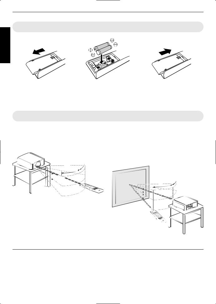
Loading Batteries into the Remote Control
Started Getting
If the remote control has to be brought closer to the projector to operate, it means that the batteries are wearing out. Replace the batteries with new ones (AAA).
Insert the batteries according to the t s marks. Be sure to insert the s end first.
If an error occurs while using the remote control, remove the batteries and wait for five minutes. Load the batteries again and operate the remote control.
Effective Range of Remote Control Unit
When aiming the remote control toward the sensor on this unit (front or rear), ensure that the distance to the sensor is within 7 m.
If the remote control fails to work properly, move closer to this unit.
This unit
30° 
30°
 20°
20°
 20°
20°
Remote Control
Control through reflection off a screen, etc.
Ensure that the total of distance A (between this unit and the screen) and distance B (between the remote control and the screen) is within 7 m.
*As the efficiency of signals reflected from the remote control unit varies with the type of screen used, the operable distance may decrease.
|
|
Screen |
|
|
|
||
|
|
|
|
30° |
30° |
|
This unit |
|
|
|
|
|
|||
|
|
|
|
|
|
||
|
|
|
|
|
|||
|
20° |
|
|
A |
|
|
|
|
|
|
|
|
|||
|
20° |
|
|
|
|
|
|
|
|
|
|
|
|
|
|
|
B |
|
|
|
|
|
|
Remote Control |
|
|
|
||||
|
|
|
|||||
|
|
|
|||||
|
|
|
|||||
|
|
|
|
|
|
|
|
 CAUTION
Do not put the remote control in a place with an exposure to direct sun light or high temperature.
18
Installing the Projector
Precautions during Installation
Please read the following carefully before installing this unit.
Do not install at the following
This unit is a precision device. Please refrain from installing or using it at the following locations. Otherwise, it may cause fire or malfunction.
Dusty, wet and humid places
Places subject to oily smoke or cigarette smoke
On top of a carpet or bedding, or other soft surfaces
Places exposed to direct sunlight
Places with a high or low temperature
Do not install this unit in a room that is oily or subject to cigarette smoke. Even a small quantity of smoke or oiliness can have a longterm impact on this unit.
*This unit produces a great amount of heat, and is designed to take in cool air to cool its optical components. Using the unit at the above locations may cause dirt to attach to the light path, thereby resulting in dark images or dull colors.
*Dirt that sticks to the optical components cannot be removed.
Maintain clearance from the wall, etc.
As the unit discharges a large amount of heat, install it with adequate clearance from the surroundings as shown below.
|
150 mm and above |
|
300 mm |
300 mm |
|
and above |
and above |
|
150 mm |
|
|
and above |
200 mm |
|
Front |
||
and above |
||
|
Leave the front area of the unit unblocked.
If there is any obstructing object in front of the exhaust vent, hot air will flow back to the unit and cause it to heat up. Hot air flowing out of the unit may cause shadows on the screen (heat haze phenomenon).
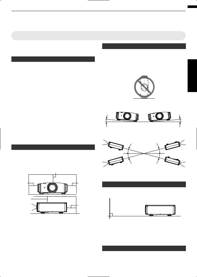
Using the projector
This unit uses a projection lamp, which will heat up when in use.
Please refrain from projecting in the following circumstances. Otherwise, it may cause fire or malfunction.
|
Projection with the unit stood vertically |
up Set |
|
|
|
|
Projection with the unit inclined at an angle |
|
Horizontal inclination: within ± 5 ° |
|
|
5° |
5° |
|
Vertical inclination: within ± 15 °
15° |
15° |
|
|
15° |
15° |
|
Malfunction may occur if the angle is not set within the abovementioned range.
Installing the screen
Install the unit and the screen such that they are perpendicular to each other.
Screen
Front 

Please choose a screen material with nonuniform patterns. Uniform patterns such as checks may cause interference patterns to occur.
In this case, you can change the size of the screen to make the interference patterns less noticeable.
Using the projector at a high altitude
When using this unit at a location that is higher than 900 m above sea level (low air pressure), set the “High Altitude Mode” to “On”. (p. 62)
19
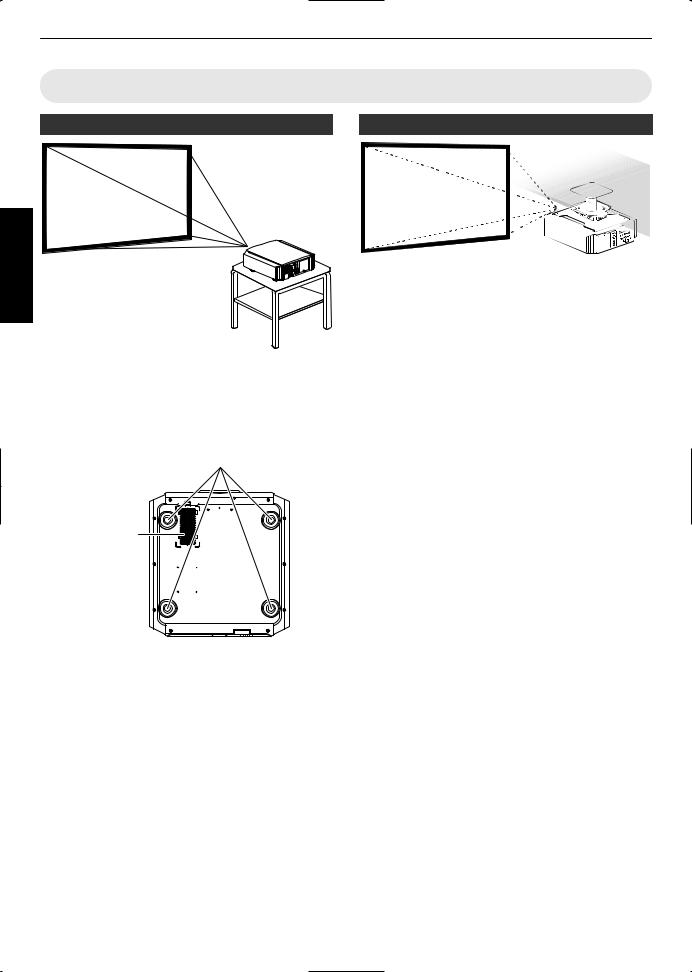
Precautions during Mounting
Securing (mounting) the projector
up Set
When this unit is to be mounted to a fixed position for use, install it horizontally.
Make sure to secure the main unit to prevent accidents such as during an earthquake.
Securing with screws
4 Locations
Air Inlets
Remove the four feet at the bottom, and fasten using the screws (M5 screws, 13 to 23 mm).
*Using screws other than those designated may cause the unit to break down.
*Leave a clearance of at least 10 mm from the bottom surface of the unit to allow it to take in cool air.
Securing the projector (ceiling mount)
Special expertise and techniques are required for mounting this unit to the ceiling. Make sure that you get the authorized dealer or a specialist to install it.
Take the necessary actions to prevent the main unit from falling off such as during an earthquake.
Regardless of the warranty period, JVC is not liable for any product damage caused by mounting the unit with nonJVC ceiling fittings or to an environment that is not suited for ceiling mount.
When using the unit with it suspended from a ceiling, pay attention to the surrounding temperature. When a heater is in use, the temperature around the ceiling may be higher than expected.
20
Adjusting the Position
Adjusting the elevation angle of the projector
The height and inclination of the unit (0 to 5 mm) can be adjusted by turning the feet.
Lift the unit and adjust the four feet.
 Feet
Feet
Extend 

 Contract
Adjusting the position of the image
By using the lens shift feature of this unit, you can shift the image upward/downward or to the left/right. Set it to your preferred position.
■ Horizontal Position
Vertical Position: 0% (Center)
Up to about 34% of the projected image
■ Vertical Position
Horizontal Position: 0 % (Center)
Up to about 80% of the projected image
up Set
■ Lens shift Range |
|
|
|||
|
90 |
|
|
|
|
(%) |
80 |
|
|
|
|
70 |
|
|
|
|
|
shift |
60 |
|
|
|
Lens movement range |
|
|
|
|
||
lens |
50 |
|
|
|
|
40 |
|
|
|
|
|
Vertical |
30 |
|
|
|
|
|
|
|
|
|
|
|
20 |
|
|
|
|
|
10 |
|
|
|
|
|
0 |
10 |
20 |
30 |
40 |
|
Horizontal lens shift (%) |
||||
The maximum vertical shift varies with the amount of horizontal shift. Similarly, the maximum horizontal shift also changes with the amount of vertical shift.
The values on the graph are intended as a guide. Use them for reference during installation.
21
Connecting the Projector
up Set
Do not turn on the power until connection is complete.
The connection procedures differ according to the device used. For details, please refer to the instruction manual of the device to be connected.
This projector is used for projecting images. To output the audio of connected devices, please connect a separate audio output device, such as an amplifier or speaker.
The images may not be displayed depending on the devices and cables to be connected. Use only HDMI cables (sold separately) that are HDMIcertified.
Some cables cannot be connected to this unit due to the size of their connector cover.
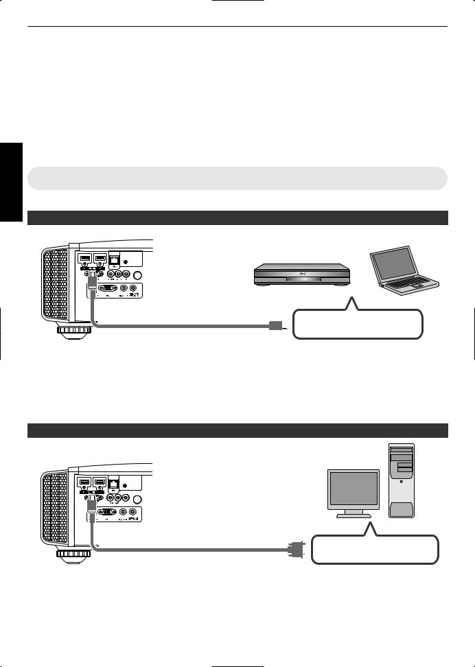
Connecting to the HDMI Input Terminal (Digital Input)
Connecting via HDMI cable
This Unit |
Laptop, etc. |
|
|
|
BD/DVD Recorder, etc. |
To [HDMI 1] or [HDMI 2] input
terminal


 HDMI Output Terminal HDMI Cable (Sold Separately)
If noise occurs, move the laptop away from this unit.
For a transmission bandwidth in compliance with the HDMI standard, a 340 MHz cable is recommended. When using a cable with a bandwidth of 75 MHz, you are recommended to set the resolution of the equipment transmitting the video to 1080i or lower.
If the video is not displayed, try to reduce the length of the cable or lower the resolution of the video transmitting equipment.
Connecting via HDMIDVI conversion cable
Desktop PC, etc.
This Unit
To [HDMI 1] or [HDMI 2] input
terminal


 DVI Output Terminal HDMI-DVI Conversion Cable (Sold Separately)
If noise occurs, move the desktop PC away from this unit.
If the video is not displayed, try to reduce the length of the cable or lower the resolution of the video transmitting equipment.
22

Connecting to the Component Video Input Terminal (Analog Input)
Connecting via component video cable
This Unit
To component video input terminals
 Component Video Cable (Sold Separately)
Set “COMP.” to “Y Pb/Cb Pr/Cr” in the setting menu. (p. 53)
Connecting via RGB video cable
This Unit
To RGB Video Input
Terminals
RGB Video Cable (Sold Separately)
BD/DVD Recorder, etc.
Component Video Output Terminals
 C R / PR (Red)
 C B / P B (Blue)
 Y (Green)
Device Equipped with RGB Output, etc.
RGB Video Output Terminals
 R (Red)
 B (Blue)
 G (Green) (Includes Sync Signal)
Set “COMP.” to “RGB” in the setting menu. (p. 53)
For more information on compatible input signals, please refer to “Specifications”p. 76.
Connecting to the PC Input Terminal
This Unit |
Laptop, etc. |
|
 To [PC] Input Terminal, etc.
 VGA Output Terminal
PC Cable (Sold Separately)
For more information on compatible signals, please refer to “Types of Possible Input Signals” (p. 79).
up Set
23
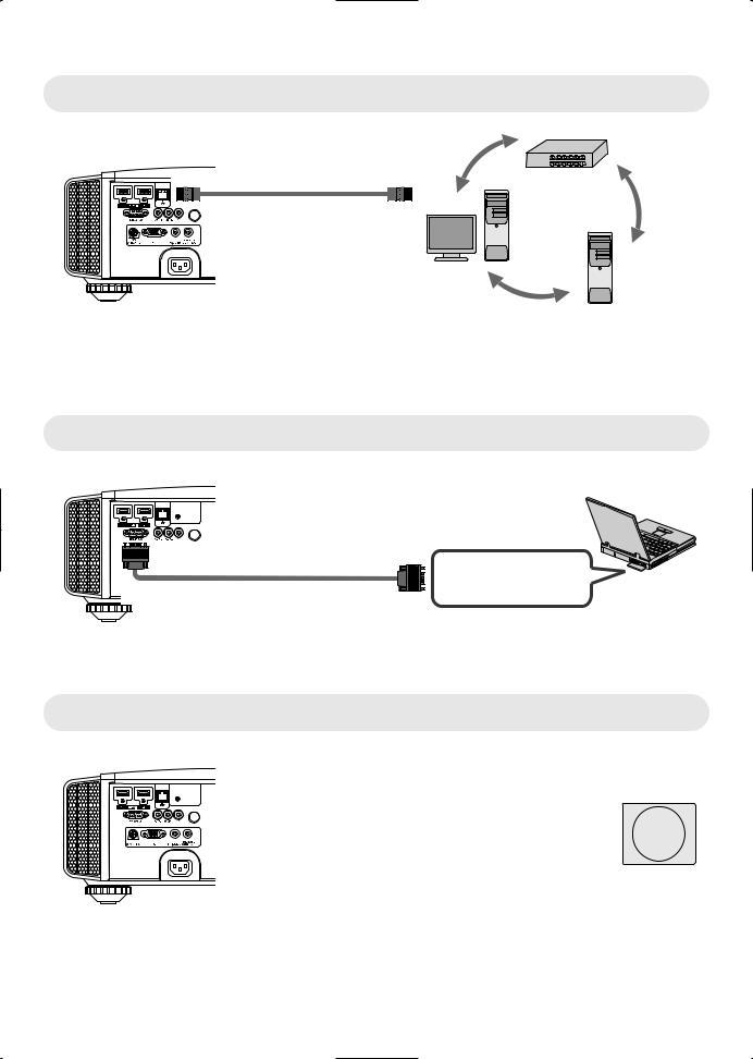
Connecting to the LAN Terminal
up Set
Hub
This Unit
To [LAN] Terminal
Network
Connection Cable
(Sold Separately)
Server
Desktop PC, etc.
The network is used to control this unit. It is not used for sending or receiving video signals.
Please contact your network administrator for information concerning the network connection.
Set “ECO Mode” to “Off” if RS232C/LAN communication is performed or the HDMI link function is used in the Standby mode. (p. 62)
For more information on control, please refer to “External Control” (p. 72).
Connecting to the RS232C Terminal
This Unit
To [RS-232C] Terminal |
RS-232C Connection Cable (Sold Separately)
Laptop, etc.
 RS-232C Terminal
Set “ECO Mode” to “Off” if RS232C/LAN communication is performed or the HDMI link function is used in the Standby mode. (p. 62)
For more information on control, please refer to “External Control” (p. 72).
Connecting to the REMOTE Terminal
This Unit
To [REMOTE] Terminal
External Infrared Sensor
Connection Cable (Sold Separately)
(Sold Separately)
For more information on the external infrared sensor and connecting cable, please contact your dealer.
24

Connecting to the TRIGGER Terminal
Screen
This Unit
To [TRIGGER] Terminal
Trigger Input Terminal (Ø3.5)
Trigger Cable (Sold Separately)
Do not use it to supply power to other devices.
Connecting to the audio terminal of another device may cause the device to malfunction or break down.
Using beyond the rated value will cause the unit to malfunction.
The trigger terminal outputs a voltage of 12 V. Exercise adequate caution to prevent short circuit.
The factory setting is “Off”. To change the setting, configure the “Trigger” item in the menu (p. 62).
Connecting the Power Cord (Supplied Accessory)
A Connect the power cord supplied to the power input terminal on the main unit
B Insert the supplied power plug into the wall outlet.
A
Power Cord (Supplied)
B
 Precautions to prevent fire and electric shock
The voltage capacity of this unit is large. Please connect it directly to the wall outlet.
When you are not using the equipment, please unplug the power cord from the outlet.
Connect it using only the power cord supplied.
Do not use a voltage other than the indicated power voltage.
Do not damage, break or modify the power cord. Do not place a heavy object on the power cord, or heat or pull it. Doing so may damage the power cord.
Do not unplug the power cord with wet hands.
up Set
25
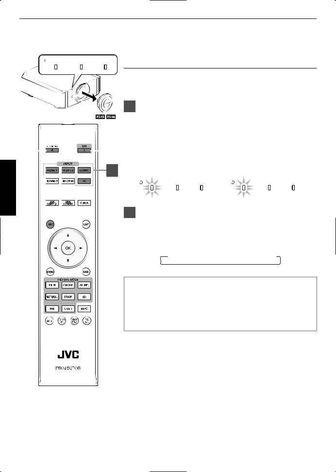
Viewing Videos
 STANDBY/ON LAMP WARNING
|
|
|
|
|
|
|
|
|
|
|
|
|
|
||
3 |
|
|
|
|
|
1 |
|
|
|
|
|||||
2
Operate
 MEMO
MEMO
When you are using , be sure to remove the lens cover.
Connect the power cord, and ensure that the “STANDBY/ON” indicator lights up in red.
Turn on the power
Remote control: press the C [ON] button
Projector unit: press the A [STANDBY/ON] button
The “STANDBY/ON” indicator light switches from red to green (light goes off after the unit starts up).
( ) The motorized lens cover opens.
“STANDBY/ON” lights up (red) |
“STANDBY/ON” lights up (green) |
||||||
|
In standby state |
|
During lamp startup |
||||
S |
TANDDBY |
/ON LAMP |
WARNING |
S |
TANDDBY |
/ON LAMP |
WARNING |
Choose the image to project
Remote control: press the [INPUT] button ([HDMI 1], [HDMI 2], [COMP.], [PC] ( only))
Projector unit: press the [INPUT] button (pressing the button each time switches the mode)
 HDMI 1
  HDMI 2
  COMP.
COMP.  PC ( KL)
Play back the selected device to project the image.
To hide the image temporarily
Press the [HIDE] button on the projector unit or remote control
The “STANDBY/ON” indicator light starts to blink in green.
Press the [HIDE] button again to resume display of the image.
The power cannot be turned off when the image is temporarily hidden.
26
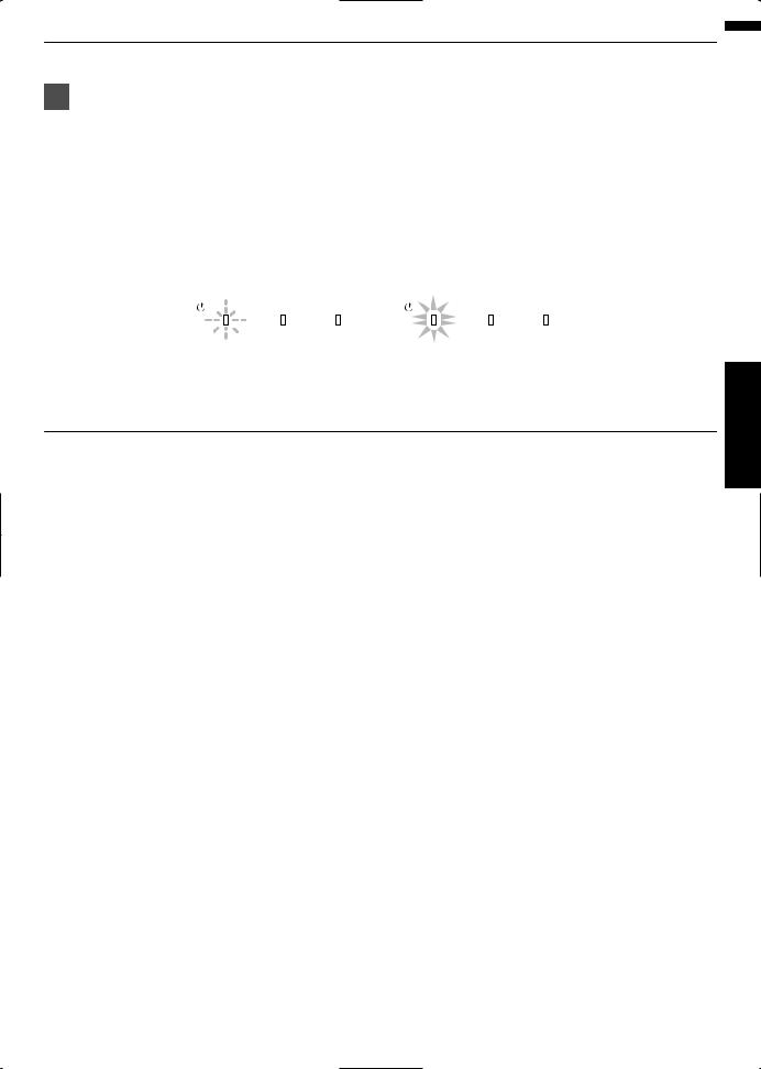
Turn off the power
Remote control: press the B [STAND BY] button
Projector unit: press the A [STANDBY/ON] button
While the “Are you sure you want to turn off?” message is displayed, press the button again.
The lamp turns off, and the “STANDBY/ON” indicator switches from a green light to a red blinking light.
After the light goes off, the fan will run for about 60 seconds to cool down the lamp (Cooldown mode) Do not disconnect the power cable while cooling is in progress.
After about 60 seconds, the “STANDBY/ON” indicator switches from a blinking red to a solid red light.
“STANDBY/ON” blinking (red) |
“STANDBY/ON” lights up (red) |
||||
In the Cool-down mode |
|
In standby state |
|||
STANDBY/ON LAMP |
WARNING |
S |
TANDDBY |
/ON LAMP |
WARNING |
( ) Attach the lens cover.
( ) The motorized lens cover closes.
 CAUTION
The power cannot be turned off within approximately 90 seconds after it has been turned on.
After the light goes off, the fan will run for about 60 seconds to cool down the lamp (Cooldown mode) Do not disconnect the power cable while cooling is in progress.
The power cannot be turned on again while cooling is in progress (60 seconds).
Pull out the power plug when the unit is not to be used for a prolonged period of time.
Operate
27

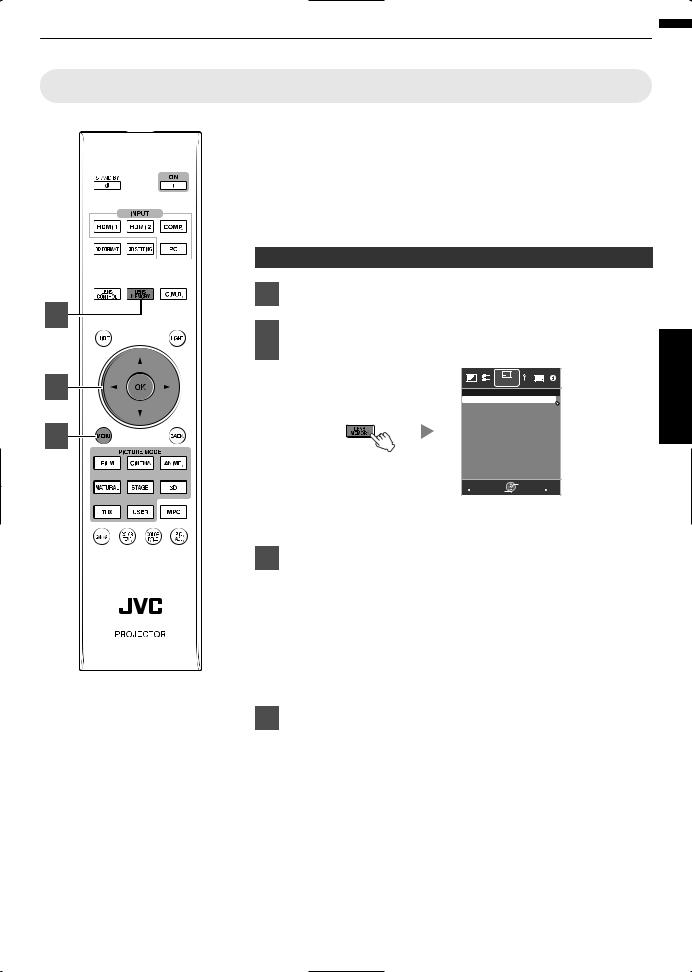
Adjusting the Projector Screen
Operate
Adjusting the Lens According to the Projection Position
Press the [LENS CONTROL] button, and use the
[JKH I] keys to adjust Focus, Zoom (screen size),
|
and Shift (screen position) |
|
Lens Control |
|
Focus |
1 |
Operate Back |
Select BACK |
Pressing the [LENS CONTROL] or [OK] button each time switches the mode in the following sequence: “Focus” “Zoom” “Shift”
“Focus”...
ABCD
2
|
Focus Adjustment |
Zoom (Screen Size) |
Shift (Screen Position) |
|
|
|
|
Adjustment |
Adjustment |
|
|
Press the [BACK] button once, or the [MENU] twice, |
||
|
|
|||
|
|
to end adjustment. |
|
|
28
Saving and Retrieving Adjustment Settings
The focus, zoom, and shift settings can be saved or retrieved, so you can switch easily to a different aspect ratio (screen size) according to the image.
Pressing the [LENS MEMORY] button each time switches the mode in the following sequence: “Lens Memory Save” “Lens Memory Select” “Lens
Memory Name Edit” “Lens Memory Save”...
In a state where no adjustment settings are saved (factory default), only “Lens Memory Save” is displayed.
Saving an adjustment data
Adjust focus, zoom, or shift (p. 28)
2 |
Press the [LENS MEMORY] button to display “Lens |
|
|
||
|
Memory Save” |
|
3 |
Installation |
|
>> Lens Memory Save |
|
|
|
----- |
|
|
----- |
|
4 |
----- |
|
----- |
|
|
|
|
|
|
----- |
|
|
----- |
|
|
----- |
|
|
----- |
|
|
----- |
|
|
----- |
|
|
Exit |
Operate Back |
|
MENU Select |
BACK |
You can also save an adjustment data by selecting “Installation”“Lens Control” “Lens Memory Save” from the menu.
Select the item to save, and press the [OK] button
The adjustment data is saved.
Items with no adjustment data saved are displayed as [].
If you have selected an item for which an adjustment data has already
been saved, the old data will be overwritten.
You can change the name when saving an item. (p. 30)
The maximum number of items can be saved is 10 for and 5 for .
Press the [MENU] button to exit
Operate
29
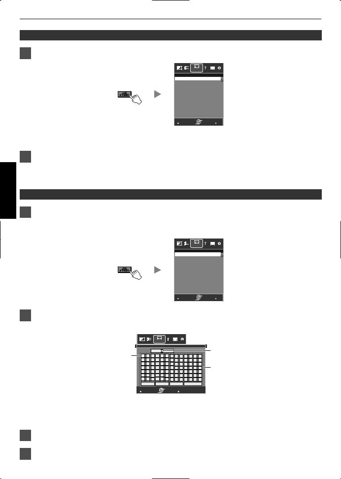
Retrieving an adjustment data
Press the [LENS MEMORY] button to display “Lens Memory Select”
Operate
Installation
>> Lens Memory Select MEMORY1
MEMORY2
-----
-----
-----
-----
-----
-----
-----
-----
Exit |
Select |
Operate Back |
MENU |
BACK |
You can also retrieve an adjustment data by selecting “Installation” “Lens Control” “Lens Memory Select” from the menu.
Select the adjustment data to retrieve, and press the [OK] button
The retrieved data is adjusted automatically.
If no adjustment data has been saved, the item will be grayed out and cannot be selected.
Renaming an adjustment data
Press the [LENS MEMORY] button to display “Lens Memory Name Edit”
You can also edit an adjustment data by selecting “Installation” “Lens Control” “Lens Memory Name Edit” from the menu.
Installation
>> Lens Memory Name Edit MEMORY1
MEMORY2
-----
-----
-----
-----
-----
-----
-----
-----
Exit |
Select |
Operate Back |
MENU |
BACK |
Select the adjustment data to edit, and press the [OK] button
An edit screen appears.
|
|
|
|
Installation |
|
|
|
|
|
|
|
|
|
|
|
>> User Name Edit |
|
|
|
|
|
|
|
|
|
Input Cursor |
|||
Selection Cursor |
|
|
User 1 |
|
|
|
|
|
|
|
|
|||
|
|
|
|
|
|
|
|
|
|
|
||||
N |
O |
P |
Q |
R |
S |
T |
U |
V |
W |
X |
Y |
Z |
|
|
|
A |
B |
C |
D |
E |
F |
G |
H |
I |
J |
K |
L |
M |
|
|
a |
b |
c |
d |
e |
f |
g |
h |
i |
j |
k |
l |
m |
Character List |
|
1 |
2 |
3 |
4 |
5 |
6 |
7 |
8 |
9 |
0 |
, . |
^ |
||
|
n |
o |
p |
q |
r |
s |
t |
y |
v |
w |
x |
y |
z |
|
|
! |
" |
# |
$ |
% |
& |
* |
+ |
- |
/ |
= |
? |
@ |
|
|
: |
; |
| |
~ |
( |
) |
< |
> |
[ |
] |
{ |
} |
\ |
|
|
SPACE |
|
Clear |
|
All Clear |
|
|
|
OK |
|
|
|||
Exit |
Select |
Operate Back |
MENU |
BACK |
You can input up to 10 characters.
Characters that are usable include alphabets (upper or lower case), numeric characters, and symbols.
Pressing the [Back] button cancels the content that is currently being edited, and exits the edit mode.
After renaming, select “OK” and press the [OK] button
Press the [MENU] button to exit
30
Loading...