

Page 1
Service and Maintenance Manual
Models
740A
740AJ
P/N - 3121160
January 8, 2013
Page 2

Page 3

INTRODUCTION
SECTION A. INTRODUCTION - MAINTENANCE SAFETY PRECAUTIONS
A GENERAL
This section contains the general safety precautions
which must be observed during maintenance of the aerial
platform. It is of utmost importance that maintenance personnel pay strict attention to these warnings and precautions to avoid possible injury to themselves or others, or
damage to the equipment. A maintenance program must
be followed to ensure that the machine is safe to operate.
MODIFICATION OR ALTERATION OF AN AERIAL WORK PLATFORM SHALL BE MADE ONLY WITH WRITTEN PERMISSION
FROM THE MANUFACTURER.
The specific precautions to be observed during maintenance are inserted at the appropriate point in the manual.
These precautions are, for the most part, those that apply
when servicing hydraulic and larger machine component
parts.
Your safety, and that of others, is the first consideration
when engaging in the maintenance of equipment. Always
be conscious of weight. Never attempt to move heavy
parts without the aid of a mechanical device. Do not allow
heavy objects to rest in an unstable position. When raising
a portion of the equipment, ensure that adequate support
is provided.
SINCE THE MACHINE MANUFACTURER HAS NO DIRECT CONTROL OVER THE FIELD INSPECTION AND MAINTENANCE,
SAFETY IN THIS AREA IS THE RESPONSIBILITY OF THE OWNER/
OPERATOR.
B HYDRAULIC SYSTEM SAFETY
It should be noted that the machines hydraulic systems
operate at extremely high potentially dangerous pressures. Every effort should be made to relieve any system
pressure prior to disconnecting or removing any portion of
the system.
C MAINTENANCE
FAILURE TO COMPLY WITH SAFETY PRECAUTIONS LISTED IN
THIS SECTION COULD RESULT IN MACHINE DAMAGE, PERSONNEL INJURY OR DEATH AND IS A SAFETY VIOLATION.
• ENSURE REPLACEMENT PARTS OR COMPONENTS
ARE IDENTICAL OR EQUIVALENT TO ORIGINAL PARTS
OR COMPONENTS.
• NO SMOKING IS MANDATORY. NEVER REFUEL DURING ELECTRICAL STORMS. ENSURE THAT FUEL
CAP IS CLOSED AND SECURE AT ALL OTHER
TIMES.
• REMOVE ALL RINGS, WATCHES AND JEWELRY
WHEN PERFORMING ANY MAINTENANCE.
• DO NOT WEAR LONG HAIR UNRESTRAINED, OR
LOOSE-FITTING CLOTHING AND NECKTIES WHICH
ARE APT TO BECOME CAUGHT ON OR ENTANGLED
IN EQUIPMENT.
• OBSERVE AND OBEY ALL WARNINGS AND CAUTIONS ON MACHINE AND IN SERVICEMANUAL.
• KEEP OIL, GREASE, WATER, ETC. WIPED FROM
STANDING SURFACES AND HAND HOLDS.
• USE CAUTION WHEN CHECKING A HOT, PRESSURIZED COOLANT SYSTEM.
• NEVER WORK UNDER AN ELEVATED BOOM UNTIL
BOOM HAS BEEN SAFELY RESTRAINED FROM ANY
MOVEMENT BY BLOCKING OR OVERHEAD SLING,
OR BOOM SAFETY PROP HAS BEEN ENGAGED.
• BEFORE MAKING ADJUSTMENTS, LUBRICATING OR
PERFORMING ANY OTHER MAINTENANCE, SHUT
OFF ALL POWER CONTROLS.
• BATTERY SHOULD ALWAYS BE DISCONNECTEDDURING REPLACEMENT OF ELECTRICAL COMPONENTS.
• KEEP ALL SUPPORT EQUIPMENT AND ATTACHMENTS STOWED IN THEIR PROPER PLACE.
• USE ONLY APPROVED, NONFLAMMABLE CLEANING
SOLVENTS.
Relieve system pressure by cycling the applicable control
several times with the engine stopped and ignition on, to
direct any line pressure back into the reservoir. Pressure
feed lines to system components can then be disconnected with minimal fluid loss.
3121160 – JLG Lift – A-1
Page 4

INTRODUCTION
REVISON LOG
Original Issue - November 4, 2002
Revised - September 8, 2003
Revised - March 10, 2006
Revised - September 28, 2007
Revised - June 3, 2008
Revised - January 8, 2013
A-2 – JLG Lift – 3121160
Page 5

TABLE OF CONTENTS
SECTION NO. TITLE PAGE NO.
SECTION A - INTRODUCTION - MAINTENANCE SAFETY PRECAUTIONS
A General . . . . . . . . . . . . . . . . . . . . . . . . . . . . . . . . . . . . . . . . . . . . . . . . . . . . . . . . . . . . . . . . . . . . . .A-1
B Hydraulic System Safety . . . . . . . . . . . . . . . . . . . . . . . . . . . . . . . . . . . . . . . . . . . . . . . . . . . . . . . . . A-1
C Maintenance . . . . . . . . . . . . . . . . . . . . . . . . . . . . . . . . . . . . . . . . . . . . . . . . . . . . . . . . . . . . . . . . . . A-1
SECTION 1 - SPECIFICATIONS
1.1 Capacities. . . . . . . . . . . . . . . . . . . . . . . . . . . . . . . . . . . . . . . . . . . . . . . . . . . . . . . . . . . . . . . . . . . .1-1
1.2 Engine Data . . . . . . . . . . . . . . . . . . . . . . . . . . . . . . . . . . . . . . . . . . . . . . . . . . . . . . . . . . . . . . . . . . .1-1
1.3 Tires . . . . . . . . . . . . . . . . . . . . . . . . . . . . . . . . . . . . . . . . . . . . . . . . . . . . . . . . . . . . . . . . . . . . . . . . . 1-2
1.4 Drive System . . . . . . . . . . . . . . . . . . . . . . . . . . . . . . . . . . . . . . . . . . . . . . . . . . . . . . . . . . . . . . . . . .1-2
1.5 Swing System . . . . . . . . . . . . . . . . . . . . . . . . . . . . . . . . . . . . . . . . . . . . . . . . . . . . . . . . . . . . . . . . .1-2
1.6 Hydraulic Drive Pump . . . . . . . . . . . . . . . . . . . . . . . . . . . . . . . . . . . . . . . . . . . . . . . . . . . . . . . . . . .1-2
1.7 Variable Displacement Pump . . . . . . . . . . . . . . . . . . . . . . . . . . . . . . . . . . . . . . . . . . . . . . . . . . . . .1-2
1.8 Hydraulic Load Sense Pump . . . . . . . . . . . . . . . . . . . . . . . . . . . . . . . . . . . . . . . . . . . . . . . . . . . . .1-2
1.9 Auxiliary Power Pump . . . . . . . . . . . . . . . . . . . . . . . . . . . . . . . . . . . . . . . . . . . . . . . . . . . . . . . . . . .1-3
1.10 Hydraulic Filter - In-line . . . . . . . . . . . . . . . . . . . . . . . . . . . . . . . . . . . . . . . . . . . . . . . . . . . . . . . . . .1-3
1.11 Compressor. . . . . . . . . . . . . . . . . . . . . . . . . . . . . . . . . . . . . . . . . . . . . . . . . . . . . . . . . . . . . . . . . . .1-3
1.12 Dimensional Data . . . . . . . . . . . . . . . . . . . . . . . . . . . . . . . . . . . . . . . . . . . . . . . . . . . . . . . . . . . . . .1-3
1.13 Operating Specifications . . . . . . . . . . . . . . . . . . . . . . . . . . . . . . . . . . . . . . . . . . . . . . . . . . . . . . . . .1-3
1.14 Function Speeds . . . . . . . . . . . . . . . . . . . . . . . . . . . . . . . . . . . . . . . . . . . . . . . . . . . . . . . . . . . . . . .1-4
Machine Orientation When Doing Speed Tests . . . . . . . . . . . . . . . . . . . . . . . . . . . . . . . . . . 1-4
Test Notes . . . . . . . . . . . . . . . . . . . . . . . . . . . . . . . . . . . . . . . . . . . . . . . . . . . . . . . . . . . . . . . 1-4
1.15 Torque Requirements . . . . . . . . . . . . . . . . . . . . . . . . . . . . . . . . . . . . . . . . . . . . . . . . . . . . . . . . . . . 1-5
1.16 Lubrication. . . . . . . . . . . . . . . . . . . . . . . . . . . . . . . . . . . . . . . . . . . . . . . . . . . . . . . . . . . . . . . . . . . .1-5
Hydraulic Oil . . . . . . . . . . . . . . . . . . . . . . . . . . . . . . . . . . . . . . . . . . . . . . . . . . . . . . . . . . . . . 1-5
1.17 Cylinder Specifications . . . . . . . . . . . . . . . . . . . . . . . . . . . . . . . . . . . . . . . . . . . . . . . . . . . . . . . . . .1-6
1.18 Major Component Weights . . . . . . . . . . . . . . . . . . . . . . . . . . . . . . . . . . . . . . . . . . . . . . . . . . . . . . .1-7
1.19 Pressure Settings . . . . . . . . . . . . . . . . . . . . . . . . . . . . . . . . . . . . . . . . . . . . . . . . . . . . . . . . . . . . . .1-7
1.20 Critical Stability Weights . . . . . . . . . . . . . . . . . . . . . . . . . . . . . . . . . . . . . . . . . . . . . . . . . . . . . . . . .1-7
1.21 Operator Maintenance . . . . . . . . . . . . . . . . . . . . . . . . . . . . . . . . . . . . . . . . . . . . . . . . . . . . . . . . . .1-8
Draining Oil Build Up From The Propane Regulator. . . . . . . . . . . . . . . . . . . . . . . . . . . . . . . 1-12
Propane Fuel Filter Replacement . . . . . . . . . . . . . . . . . . . . . . . . . . . . . . . . . . . . . . . . . . . . . 1-13
Propane Fuel System Pressure Relief . . . . . . . . . . . . . . . . . . . . . . . . . . . . . . . . . . . . . . . . . . 1-14
SECTION 2 - GENERAL
2.1 Machine Preparation, Inspection, and Maintenance . . . . . . . . . . . . . . . . . . . . . . . . . . . . . . . . . . .2-1
General. . . . . . . . . . . . . . . . . . . . . . . . . . . . . . . . . . . . . . . . . . . . . . . . . . . . . . . . . . . . . . . . . . 2-1
Preparation, Inspection, and Maintenance . . . . . . . . . . . . . . . . . . . . . . . . . . . . . . . . . . . . . . 2-1
Pre-Start Inspection . . . . . . . . . . . . . . . . . . . . . . . . . . . . . . . . . . . . . . . . . . . . . . . . . . . . . . . . 2-1
Pre-Delivery Inspection and Frequent Inspection . . . . . . . . . . . . . . . . . . . . . . . . . . . . . . . . . 2-1
Annual Machine Inspection . . . . . . . . . . . . . . . . . . . . . . . . . . . . . . . . . . . . . . . . . . . . . . . . . . 2-1
Preventative Maintenance . . . . . . . . . . . . . . . . . . . . . . . . . . . . . . . . . . . . . . . . . . . . . . . . . . . 2-1
2.2 Service and Guidelines . . . . . . . . . . . . . . . . . . . . . . . . . . . . . . . . . . . . . . . . . . . . . . . . . . . . . . . . . .2-2
General. . . . . . . . . . . . . . . . . . . . . . . . . . . . . . . . . . . . . . . . . . . . . . . . . . . . . . . . . . . . . . . . . . 2-2
Safety and Workmanship . . . . . . . . . . . . . . . . . . . . . . . . . . . . . . . . . . . . . . . . . . . . . . . . . . . 2-2
Cleanliness. . . . . . . . . . . . . . . . . . . . . . . . . . . . . . . . . . . . . . . . . . . . . . . . . . . . . . . . . . . . . . . 2-2
Components Removal and Installation . . . . . . . . . . . . . . . . . . . . . . . . . . . . . . . . . . . . . . . . . 2-2
Component Disassembly and Reassembly . . . . . . . . . . . . . . . . . . . . . . . . . . . . . . . . . . . . . 2-3
Pressure-Fit Parts. . . . . . . . . . . . . . . . . . . . . . . . . . . . . . . . . . . . . . . . . . . . . . . . . . . . . . . . . . 2-3
Bearings . . . . . . . . . . . . . . . . . . . . . . . . . . . . . . . . . . . . . . . . . . . . . . . . . . . . . . . . . . . . . . . . . 2-3
Gaskets . . . . . . . . . . . . . . . . . . . . . . . . . . . . . . . . . . . . . . . . . . . . . . . . . . . . . . . . . . . . . . . . . 2-3
Bolt Usage and Torque Application . . . . . . . . . . . . . . . . . . . . . . . . . . . . . . . . . . . . . . . . . . . 2-3
Hydraulic Lines and Electrical Wiring . . . . . . . . . . . . . . . . . . . . . . . . . . . . . . . . . . . . . . . . . . 2-3
Hydraulic System. . . . . . . . . . . . . . . . . . . . . . . . . . . . . . . . . . . . . . . . . . . . . . . . . . . . . . . . . . 2-3
Lubrication . . . . . . . . . . . . . . . . . . . . . . . . . . . . . . . . . . . . . . . . . . . . . . . . . . . . . . . . . . . . . . . 2-3
Battery . . . . . . . . . . . . . . . . . . . . . . . . . . . . . . . . . . . . . . . . . . . . . . . . . . . . . . . . . . . . . . . . . . 2-3
Lubrication and Servicing . . . . . . . . . . . . . . . . . . . . . . . . . . . . . . . . . . . . . . . . . . . . . . . . . . . 2-3
3121160 – JLG Lift – i
Page 6

TABLE OF CONTENTS
SECTION NO. TITLE PAGE NO.
2.3 Lubrication and Information . . . . . . . . . . . . . . . . . . . . . . . . . . . . . . . . . . . . . . . . . . . . . . . . . . . . . . 2-3
Hydraulic System. . . . . . . . . . . . . . . . . . . . . . . . . . . . . . . . . . . . . . . . . . . . . . . . . . . . . . . . . . 2-3
Hydraulic Oil . . . . . . . . . . . . . . . . . . . . . . . . . . . . . . . . . . . . . . . . . . . . . . . . . . . . . . . . . . . . . 2-4
Changing Hydraulic Oil . . . . . . . . . . . . . . . . . . . . . . . . . . . . . . . . . . . . . . . . . . . . . . . . . . . . . 2-4
Lubrication Specifications . . . . . . . . . . . . . . . . . . . . . . . . . . . . . . . . . . . . . . . . . . . . . . . . . . . 2-4
2.4 Cylinder Drift Test . . . . . . . . . . . . . . . . . . . . . . . . . . . . . . . . . . . . . . . . . . . . . . . . . . . . . . . . . . . . . .2-4
Platform Drift . . . . . . . . . . . . . . . . . . . . . . . . . . . . . . . . . . . . . . . . . . . . . . . . . . . . . . . . . . . . . 2-4
Cylinder Drift . . . . . . . . . . . . . . . . . . . . . . . . . . . . . . . . . . . . . . . . . . . . . . . . . . . . . . . . . . . . . 2-4
2.5 Pins and Composite Bearing Repair Guidelines . . . . . . . . . . . . . . . . . . . . . . . . . . . . . . . . . . . . . .2-5
2.6 Welding on JLG Equipment . . . . . . . . . . . . . . . . . . . . . . . . . . . . . . . . . . . . . . . . . . . . . . . . . . . . . . 2-5
Do the Following When Welding on JLG Equipment . . . . . . . . . . . . . . . . . . . . . . . . . . . . . . 2-5
Do NOT Do the Following When Welding on JLG Equipment . . . . . . . . . . . . . . . . . . . . . . . 2-5
SECTION 3 - CHASSIS & TURNTABLE
3.1 Tires & Wheels. . . . . . . . . . . . . . . . . . . . . . . . . . . . . . . . . . . . . . . . . . . . . . . . . . . . . . . . . . . . . . . . . 3-1
Tire Inflation . . . . . . . . . . . . . . . . . . . . . . . . . . . . . . . . . . . . . . . . . . . . . . . . . . . . . . . . . . . . . . 3-1
Tire Damage . . . . . . . . . . . . . . . . . . . . . . . . . . . . . . . . . . . . . . . . . . . . . . . . . . . . . . . . . . . . . 3-1
Tire Replacement. . . . . . . . . . . . . . . . . . . . . . . . . . . . . . . . . . . . . . . . . . . . . . . . . . . . . . . . . . 3-1
Wheel Replacement. . . . . . . . . . . . . . . . . . . . . . . . . . . . . . . . . . . . . . . . . . . . . . . . . . . . . . . . 3-1
Wheel Installation. . . . . . . . . . . . . . . . . . . . . . . . . . . . . . . . . . . . . . . . . . . . . . . . . . . . . . . . . . 3-1
3.2 Oscillating Axle Bleeding Procedure And Lockout Test . . . . . . . . . . . . . . . . . . . . . . . . . . . . . . . . . 3-2
Lockout Cylinder Bleeding . . . . . . . . . . . . . . . . . . . . . . . . . . . . . . . . . . . . . . . . . . . . . . . . . . 3-2
Oscillating Axle Lockout Test . . . . . . . . . . . . . . . . . . . . . . . . . . . . . . . . . . . . . . . . . . . . . . . . 3-3
3.3 Free Wheeling Option . . . . . . . . . . . . . . . . . . . . . . . . . . . . . . . . . . . . . . . . . . . . . . . . . . . . . . . . . . .3-3
To Disengage Drive Motors and Brakes (Free Wheel) for Emergency Towing . . . . . . . . . . 3-3
To Engage Drive Motors and Brakes (Normal Operation) . . . . . . . . . . . . . . . . . . . . . . . . . . 3-3
3.4 Torque Hub, Drive . . . . . . . . . . . . . . . . . . . . . . . . . . . . . . . . . . . . . . . . . . . . . . . . . . . . . . . . . . . . . . 3-4
Disassembly. . . . . . . . . . . . . . . . . . . . . . . . . . . . . . . . . . . . . . . . . . . . . . . . . . . . . . . . . . . . . . 3-4
Cleaning and Inspection . . . . . . . . . . . . . . . . . . . . . . . . . . . . . . . . . . . . . . . . . . . . . . . . . . . . 3-4
Repair. . . . . . . . . . . . . . . . . . . . . . . . . . . . . . . . . . . . . . . . . . . . . . . . . . . . . . . . . . . . . . . . . . . 3-4
Assembly . . . . . . . . . . . . . . . . . . . . . . . . . . . . . . . . . . . . . . . . . . . . . . . . . . . . . . . . . . . . . . . . 3-6
3.5 Drive Brake - Ausco (Prior to S/N 56875) . . . . . . . . . . . . . . . . . . . . . . . . . . . . . . . . . . . . . . . . . . . .3-12
Disassembly. . . . . . . . . . . . . . . . . . . . . . . . . . . . . . . . . . . . . . . . . . . . . . . . . . . . . . . . . . . . . . 3-12
Inspection . . . . . . . . . . . . . . . . . . . . . . . . . . . . . . . . . . . . . . . . . . . . . . . . . . . . . . . . . . . . . . . 3-12
Assembly . . . . . . . . . . . . . . . . . . . . . . . . . . . . . . . . . . . . . . . . . . . . . . . . . . . . . . . . . . . . . . . . 3-12
3.6 Drive Brake - Mico (S/N 56875 to 83332) . . . . . . . . . . . . . . . . . . . . . . . . . . . . . . . . . . . . . . . . . . . .3-14
Disassembly. . . . . . . . . . . . . . . . . . . . . . . . . . . . . . . . . . . . . . . . . . . . . . . . . . . . . . . . . . . . . . 3-14
Assembly . . . . . . . . . . . . . . . . . . . . . . . . . . . . . . . . . . . . . . . . . . . . . . . . . . . . . . . . . . . . . . . . 3-14
Bleeding. . . . . . . . . . . . . . . . . . . . . . . . . . . . . . . . . . . . . . . . . . . . . . . . . . . . . . . . . . . . . . . . . 3-16
3.7 Drive Brake (S/N 83332 to Present) . . . . . . . . . . . . . . . . . . . . . . . . . . . . . . . . . . . . . . . . . . . . . . . . 3-17
Disassembly. . . . . . . . . . . . . . . . . . . . . . . . . . . . . . . . . . . . . . . . . . . . . . . . . . . . . . . . . . . . . . 3-17
Inspection . . . . . . . . . . . . . . . . . . . . . . . . . . . . . . . . . . . . . . . . . . . . . . . . . . . . . . . . . . . . . . . 3-17
Assembly . . . . . . . . . . . . . . . . . . . . . . . . . . . . . . . . . . . . . . . . . . . . . . . . . . . . . . . . . . . . . . . . 3-17
3.8 Drive Motor (Prior to S/N 83332). . . . . . . . . . . . . . . . . . . . . . . . . . . . . . . . . . . . . . . . . . . . . . . . . . .3-19
Spare Parts Kits . . . . . . . . . . . . . . . . . . . . . . . . . . . . . . . . . . . . . . . . . . . . . . . . . . . . . . . . . . . 3-19
Replacing the Drive Shaft Seal . . . . . . . . . . . . . . . . . . . . . . . . . . . . . . . . . . . . . . . . . . . . . . . 3-20
Disassembly and Assembly . . . . . . . . . . . . . . . . . . . . . . . . . . . . . . . . . . . . . . . . . . . . . . . . . 3-21
Assembly Notes. . . . . . . . . . . . . . . . . . . . . . . . . . . . . . . . . . . . . . . . . . . . . . . . . . . . . . . . . . . 3-25
Taper Roller Bearing Initial Tension . . . . . . . . . . . . . . . . . . . . . . . . . . . . . . . . . . . . . . . . . . . 3-25
Testing and Setup . . . . . . . . . . . . . . . . . . . . . . . . . . . . . . . . . . . . . . . . . . . . . . . . . . . . . . . . . 3-27
3.9 Drive Motor Adjustment Procedure (Prior to S/N 83332) . . . . . . . . . . . . . . . . . . . . . . . . . . . . . . . .3-27
3.10 Drive Motor (S/N 83332 to Present) . . . . . . . . . . . . . . . . . . . . . . . . . . . . . . . . . . . . . . . . . . . . . . . . 3-28
Description. . . . . . . . . . . . . . . . . . . . . . . . . . . . . . . . . . . . . . . . . . . . . . . . . . . . . . . . . . . . . . . 3-28
Shaft Seal Replacement . . . . . . . . . . . . . . . . . . . . . . . . . . . . . . . . . . . . . . . . . . . . . . . . . . . . 3-28
Loop Flushing Valve . . . . . . . . . . . . . . . . . . . . . . . . . . . . . . . . . . . . . . . . . . . . . . . . . . . . . . . 3-29
Troubleshooting. . . . . . . . . . . . . . . . . . . . . . . . . . . . . . . . . . . . . . . . . . . . . . . . . . . . . . . . . . . 3-30
Disassembly. . . . . . . . . . . . . . . . . . . . . . . . . . . . . . . . . . . . . . . . . . . . . . . . . . . . . . . . . . . . . . 3-31
Inspection . . . . . . . . . . . . . . . . . . . . . . . . . . . . . . . . . . . . . . . . . . . . . . . . . . . . . . . . . . . . . . . 3-35
ii – JLG Lift – 3121160
Page 7

TABLE OF CONTENTS
SECTION NO. TITLE PAGE NO.
Assembly . . . . . . . . . . . . . . . . . . . . . . . . . . . . . . . . . . . . . . . . . . . . . . . . . . . . . . . . . . . . . . . . 3-37
Initial Start-up Procedures . . . . . . . . . . . . . . . . . . . . . . . . . . . . . . . . . . . . . . . . . . . . . . . . . . . 3-42
3.11 Swing Hub installation. . . . . . . . . . . . . . . . . . . . . . . . . . . . . . . . . . . . . . . . . . . . . . . . . . . . . . . . . . .3-43
3.12 Swing Bearing . . . . . . . . . . . . . . . . . . . . . . . . . . . . . . . . . . . . . . . . . . . . . . . . . . . . . . . . . . . . . . . . .3-44
Turntable Bearing Mounting Bolt Condition Check . . . . . . . . . . . . . . . . . . . . . . . . . . . . . . . 3-44
Wear Tolerance . . . . . . . . . . . . . . . . . . . . . . . . . . . . . . . . . . . . . . . . . . . . . . . . . . . . . . . . . . . 3-47
Swing Bearing Replacement . . . . . . . . . . . . . . . . . . . . . . . . . . . . . . . . . . . . . . . . . . . . . . . . . 3-47
Swing Bearing Torque Values . . . . . . . . . . . . . . . . . . . . . . . . . . . . . . . . . . . . . . . . . . . . . . . . 3-49
3.13 Swing Hub (Prior to S/N 0300068040) . . . . . . . . . . . . . . . . . . . . . . . . . . . . . . . . . . . . . . . . . . . . . .3-49
Disassembly. . . . . . . . . . . . . . . . . . . . . . . . . . . . . . . . . . . . . . . . . . . . . . . . . . . . . . . . . . . . . . 3-49
Assembly . . . . . . . . . . . . . . . . . . . . . . . . . . . . . . . . . . . . . . . . . . . . . . . . . . . . . . . . . . . . . . . . 3-50
Hub Shaft Sub-Assembly . . . . . . . . . . . . . . . . . . . . . . . . . . . . . . . . . . . . . . . . . . . . . . . . . . . 3-53
Carrier Sub-Assembly . . . . . . . . . . . . . . . . . . . . . . . . . . . . . . . . . . . . . . . . . . . . . . . . . . . . . . 3-55
3.14 Swing Brake - Ausco (Prior to S/N 0300068040) . . . . . . . . . . . . . . . . . . . . . . . . . . . . . . . . . . . . . .3-58
Disassembly. . . . . . . . . . . . . . . . . . . . . . . . . . . . . . . . . . . . . . . . . . . . . . . . . . . . . . . . . . . . . . 3-58
Inspection . . . . . . . . . . . . . . . . . . . . . . . . . . . . . . . . . . . . . . . . . . . . . . . . . . . . . . . . . . . . . . . 3-58
Assembly . . . . . . . . . . . . . . . . . . . . . . . . . . . . . . . . . . . . . . . . . . . . . . . . . . . . . . . . . . . . . . . . 3-58
3.15 Swing Motor (Eaton) (Prior to S/N 0300068040) . . . . . . . . . . . . . . . . . . . . . . . . . . . . . . . . . . . . . .3-60
Disassembly. . . . . . . . . . . . . . . . . . . . . . . . . . . . . . . . . . . . . . . . . . . . . . . . . . . . . . . . . . . . . . 3-60
Reassembly . . . . . . . . . . . . . . . . . . . . . . . . . . . . . . . . . . . . . . . . . . . . . . . . . . . . . . . . . . . . . . 3-61
Motor Timing . . . . . . . . . . . . . . . . . . . . . . . . . . . . . . . . . . . . . . . . . . . . . . . . . . . . . . . . . . . . . 3-62
3.16 Swing Hub (S/N 0300068040 to Present) . . . . . . . . . . . . . . . . . . . . . . . . . . . . . . . . . . . . . . . . . . . .3-64
Disassembly. . . . . . . . . . . . . . . . . . . . . . . . . . . . . . . . . . . . . . . . . . . . . . . . . . . . . . . . . . . . . . 3-64
Main Assembly Procedure. . . . . . . . . . . . . . . . . . . . . . . . . . . . . . . . . . . . . . . . . . . . . . . . . . . 3-64
Hub Shaft Sub-Assembly . . . . . . . . . . . . . . . . . . . . . . . . . . . . . . . . . . . . . . . . . . . . . . . . . . . 3-67
Carrier Sub-Assembly . . . . . . . . . . . . . . . . . . . . . . . . . . . . . . . . . . . . . . . . . . . . . . . . . . . . . . 3-69
3.17 Swing Brake (S/N 0300068040 to Present) . . . . . . . . . . . . . . . . . . . . . . . . . . . . . . . . . . . . . . . . . .3-72
Disassembly. . . . . . . . . . . . . . . . . . . . . . . . . . . . . . . . . . . . . . . . . . . . . . . . . . . . . . . . . . . . . . 3-72
Assembly . . . . . . . . . . . . . . . . . . . . . . . . . . . . . . . . . . . . . . . . . . . . . . . . . . . . . . . . . . . . . . . . 3-72
3.18 Swing Motor (S/N 0300068040 to Present) . . . . . . . . . . . . . . . . . . . . . . . . . . . . . . . . . . . . . . . . . .3-74
Disassembly. . . . . . . . . . . . . . . . . . . . . . . . . . . . . . . . . . . . . . . . . . . . . . . . . . . . . . . . . . . . . . 3-74
Inspection and Cleaning . . . . . . . . . . . . . . . . . . . . . . . . . . . . . . . . . . . . . . . . . . . . . . . . . . . . 3-76
Assembly . . . . . . . . . . . . . . . . . . . . . . . . . . . . . . . . . . . . . . . . . . . . . . . . . . . . . . . . . . . . . . . . 3-76
Timing Procedure . . . . . . . . . . . . . . . . . . . . . . . . . . . . . . . . . . . . . . . . . . . . . . . . . . . . . . . . . 3-78
3.19 Rotary Coupling. . . . . . . . . . . . . . . . . . . . . . . . . . . . . . . . . . . . . . . . . . . . . . . . . . . . . . . . . . . . . . . .3-81
3.20 Tilt Alarm Switch (Prior to S/N 0300062045). . . . . . . . . . . . . . . . . . . . . . . . . . . . . . . . . . . . . . . . . .3-85
Manual Adjustment. . . . . . . . . . . . . . . . . . . . . . . . . . . . . . . . . . . . . . . . . . . . . . . . . . . . . . . . . 3-85
3.21 Spark Arrester Cleaning Instructions . . . . . . . . . . . . . . . . . . . . . . . . . . . . . . . . . . . . . . . . . . . . . . .3-85
3.22 Generator. . . . . . . . . . . . . . . . . . . . . . . . . . . . . . . . . . . . . . . . . . . . . . . . . . . . . . . . . . . . . . . . . . . . .3-88
Every 250 hours . . . . . . . . . . . . . . . . . . . . . . . . . . . . . . . . . . . . . . . . . . . . . . . . . . . . . . . . . . . 3-88
Every 500 hours . . . . . . . . . . . . . . . . . . . . . . . . . . . . . . . . . . . . . . . . . . . . . . . . . . . . . . . . . . . 3-88
Overload Protection. . . . . . . . . . . . . . . . . . . . . . . . . . . . . . . . . . . . . . . . . . . . . . . . . . . . . . . . 3-88
Inspecting Brushes, Replacing Brushes, and Cleaning Slip Rings . . . . . . . . . . . . . . . . . . . 3-88
3.23 Dual Fuel System . . . . . . . . . . . . . . . . . . . . . . . . . . . . . . . . . . . . . . . . . . . . . . . . . . . . . . . . . . . . . .3-90
Changing from Gasoline to LP Gas. . . . . . . . . . . . . . . . . . . . . . . . . . . . . . . . . . . . . . . . . . . . 3-90
Changing from LP Gas to Gasoline. . . . . . . . . . . . . . . . . . . . . . . . . . . . . . . . . . . . . . . . . . . . 3-90
3.24 EFI Engine . . . . . . . . . . . . . . . . . . . . . . . . . . . . . . . . . . . . . . . . . . . . . . . . . . . . . . . . . . . . . . . . . . . .3-90
Performing Diagnostics . . . . . . . . . . . . . . . . . . . . . . . . . . . . . . . . . . . . . . . . . . . . . . . . . . . . . 3-90
Engine Module and Sensors . . . . . . . . . . . . . . . . . . . . . . . . . . . . . . . . . . . . . . . . . . . . . . . . . 3-91
Fuel System . . . . . . . . . . . . . . . . . . . . . . . . . . . . . . . . . . . . . . . . . . . . . . . . . . . . . . . . . . . . . . 3-105
3.25 Ford LPG System (S/N 0300077500 To Present) . . . . . . . . . . . . . . . . . . . . . . . . . . . . . . . . . . . . . .3-110
Description. . . . . . . . . . . . . . . . . . . . . . . . . . . . . . . . . . . . . . . . . . . . . . . . . . . . . . . . . . . . . . . 3-110
Regulator . . . . . . . . . . . . . . . . . . . . . . . . . . . . . . . . . . . . . . . . . . . . . . . . . . . . . . . . . . . . . . . . 3-110
Megajector . . . . . . . . . . . . . . . . . . . . . . . . . . . . . . . . . . . . . . . . . . . . . . . . . . . . . . . . . . . . . . . 3-110
Mixer. . . . . . . . . . . . . . . . . . . . . . . . . . . . . . . . . . . . . . . . . . . . . . . . . . . . . . . . . . . . . . . . . . . . 3-110
Lockoff Solenoid . . . . . . . . . . . . . . . . . . . . . . . . . . . . . . . . . . . . . . . . . . . . . . . . . . . . . . . . . . 3-112
Megajector Diagnostic Code Descriptions . . . . . . . . . . . . . . . . . . . . . . . . . . . . . . . . . . . . . . 3-112
3.26 Deutz EMR 2 (S/N 85331 to Present) . . . . . . . . . . . . . . . . . . . . . . . . . . . . . . . . . . . . . . . . . . . . . . .3-113
3121160 – JLG Lift – iii
Page 8

TABLE OF CONTENTS
SECTION NO. TITLE PAGE NO.
3.27 GM Engine General Maintenance. . . . . . . . . . . . . . . . . . . . . . . . . . . . . . . . . . . . . . . . . . . . . . . . . .3-126
Maintenance of the Drive Belt . . . . . . . . . . . . . . . . . . . . . . . . . . . . . . . . . . . . . . . . . . . . . . . . 3-126
Engine Electrical System Maintenance. . . . . . . . . . . . . . . . . . . . . . . . . . . . . . . . . . . . . . . . . 3-126
Checking/Filling Engine Oil Level . . . . . . . . . . . . . . . . . . . . . . . . . . . . . . . . . . . . . . . . . . . . . 3-126
Changing The Engine Oil . . . . . . . . . . . . . . . . . . . . . . . . . . . . . . . . . . . . . . . . . . . . . . . . . . . 3-127
Coolant Fill Procedure - Dual Fuel Engine . . . . . . . . . . . . . . . . . . . . . . . . . . . . . . . . . . . . . . 3-127
3.28 GM Engine Dual Fuel System . . . . . . . . . . . . . . . . . . . . . . . . . . . . . . . . . . . . . . . . . . . . . . . . . . . . .3-129
Fuel Filter . . . . . . . . . . . . . . . . . . . . . . . . . . . . . . . . . . . . . . . . . . . . . . . . . . . . . . . . . . . . . . . . 3-129
Electric Lock Off. . . . . . . . . . . . . . . . . . . . . . . . . . . . . . . . . . . . . . . . . . . . . . . . . . . . . . . . . . . 3-129
EPR Assembly . . . . . . . . . . . . . . . . . . . . . . . . . . . . . . . . . . . . . . . . . . . . . . . . . . . . . . . . . . . . 3-129
Low Pressure Regulator (LPR) . . . . . . . . . . . . . . . . . . . . . . . . . . . . . . . . . . . . . . . . . . . . . . . 3-130
Air Fuel Mixer . . . . . . . . . . . . . . . . . . . . . . . . . . . . . . . . . . . . . . . . . . . . . . . . . . . . . . . . . . . . . 3-130
Electronic Throttle Control (ETC) . . . . . . . . . . . . . . . . . . . . . . . . . . . . . . . . . . . . . . . . . . . . . 3-131
Engine Control Module . . . . . . . . . . . . . . . . . . . . . . . . . . . . . . . . . . . . . . . . . . . . . . . . . . . . . 3-131
Heated Exhaust Gas Oxygen Sensor . . . . . . . . . . . . . . . . . . . . . . . . . . . . . . . . . . . . . . . . . . 3-132
Gasoline Multi Point Fuel Injection System (MPFI) . . . . . . . . . . . . . . . . . . . . . . . . . . . . . . . . 3-132
Gasoline Fuel Pump . . . . . . . . . . . . . . . . . . . . . . . . . . . . . . . . . . . . . . . . . . . . . . . . . . . . . . . 3-132
Gasoline Pressure And Temperature Sensor Manifold. . . . . . . . . . . . . . . . . . . . . . . . . . . . . 3-132
Fuel Filter . . . . . . . . . . . . . . . . . . . . . . . . . . . . . . . . . . . . . . . . . . . . . . . . . . . . . . . . . . . . . . . . 3-133
Fuel Injector Rail . . . . . . . . . . . . . . . . . . . . . . . . . . . . . . . . . . . . . . . . . . . . . . . . . . . . . . . . . . 3-133
Fuel Injector . . . . . . . . . . . . . . . . . . . . . . . . . . . . . . . . . . . . . . . . . . . . . . . . . . . . . . . . . . . . . . 3-133
3.29 GM Engine Fuel System Repair . . . . . . . . . . . . . . . . . . . . . . . . . . . . . . . . . . . . . . . . . . . . . . . . . . .3-133
Propane Fuel System Pressure Relief. . . . . . . . . . . . . . . . . . . . . . . . . . . . . . . . . . . . . . . . . . 3-133
Propane Fuel System Leak Test . . . . . . . . . . . . . . . . . . . . . . . . . . . . . . . . . . . . . . . . . . . . . . 3-133
Propane Fuel Filter Replacement . . . . . . . . . . . . . . . . . . . . . . . . . . . . . . . . . . . . . . . . . . . . . 3-134
Electronic Pressure Regulator (EPR) Assembly Replacement. . . . . . . . . . . . . . . . . . . . . . . 3-135
Temperature Manifold Absolute Pressure (TMAP) Sensor . . . . . . . . . . . . . . . . . . . . . . . . . . 3-136
Electronic Throttle Control Replacement . . . . . . . . . . . . . . . . . . . . . . . . . . . . . . . . . . . . . . . 3-137
Mixer Replacement . . . . . . . . . . . . . . . . . . . . . . . . . . . . . . . . . . . . . . . . . . . . . . . . . . . . . . . . 3-138
Coolant Hose Replacement . . . . . . . . . . . . . . . . . . . . . . . . . . . . . . . . . . . . . . . . . . . . . . . . . 3-138
Vapor Hose Replacement . . . . . . . . . . . . . . . . . . . . . . . . . . . . . . . . . . . . . . . . . . . . . . . . . . . 3-138
Engine Control Module Replacement . . . . . . . . . . . . . . . . . . . . . . . . . . . . . . . . . . . . . . . . . . 3-139
Heated Exhaust Gas Oxygen Sensor Replacement . . . . . . . . . . . . . . . . . . . . . . . . . . . . . . . 3-139
3.30 GM Engine LPG Fuel System Diagnosis . . . . . . . . . . . . . . . . . . . . . . . . . . . . . . . . . . . . . . . . . . . .3-139
Fuel System Description . . . . . . . . . . . . . . . . . . . . . . . . . . . . . . . . . . . . . . . . . . . . . . . . . . . . 3-139
Diagnostic Aids . . . . . . . . . . . . . . . . . . . . . . . . . . . . . . . . . . . . . . . . . . . . . . . . . . . . . . . . . . . 3-140
3.31 Air Compressor . . . . . . . . . . . . . . . . . . . . . . . . . . . . . . . . . . . . . . . . . . . . . . . . . . . . . . . . . . . . . . . .3-154
Description. . . . . . . . . . . . . . . . . . . . . . . . . . . . . . . . . . . . . . . . . . . . . . . . . . . . . . . . . . . . . . . 3-154
Oil Injection . . . . . . . . . . . . . . . . . . . . . . . . . . . . . . . . . . . . . . . . . . . . . . . . . . . . . . . . . . . . . . 3-154
Inlet Valve and Control Valving . . . . . . . . . . . . . . . . . . . . . . . . . . . . . . . . . . . . . . . . . . . . . . . 3-154
Air Filter Unit . . . . . . . . . . . . . . . . . . . . . . . . . . . . . . . . . . . . . . . . . . . . . . . . . . . . . . . . . . . . . 3-154
Oil Reservoir and Primary Oil Separation . . . . . . . . . . . . . . . . . . . . . . . . . . . . . . . . . . . . . . . 3-154
Secondary Spin-On Oil Coalescer/Separator . . . . . . . . . . . . . . . . . . . . . . . . . . . . . . . . . . . . 3-154
Spin-On Oil Filter . . . . . . . . . . . . . . . . . . . . . . . . . . . . . . . . . . . . . . . . . . . . . . . . . . . . . . . . . . 3-154
Minimum Pressure Valve/Check Valve Assembly. . . . . . . . . . . . . . . . . . . . . . . . . . . . . . . . . 3-156
Hydraulic Drive System . . . . . . . . . . . . . . . . . . . . . . . . . . . . . . . . . . . . . . . . . . . . . . . . . . . . . 3-156
Compressor Cooling System . . . . . . . . . . . . . . . . . . . . . . . . . . . . . . . . . . . . . . . . . . . . . . . . 3-156
Initial Startup . . . . . . . . . . . . . . . . . . . . . . . . . . . . . . . . . . . . . . . . . . . . . . . . . . . . . . . . . . . . . 3-156
Normal Startup Procedure. . . . . . . . . . . . . . . . . . . . . . . . . . . . . . . . . . . . . . . . . . . . . . . . . . . 3-157
Normal Shutdown Procedure . . . . . . . . . . . . . . . . . . . . . . . . . . . . . . . . . . . . . . . . . . . . . . . . 3-157
Daily Operation . . . . . . . . . . . . . . . . . . . . . . . . . . . . . . . . . . . . . . . . . . . . . . . . . . . . . . . . . . . 3-157
General Maintenance . . . . . . . . . . . . . . . . . . . . . . . . . . . . . . . . . . . . . . . . . . . . . . . . . . . . . . 3-157
Lubrication Guide . . . . . . . . . . . . . . . . . . . . . . . . . . . . . . . . . . . . . . . . . . . . . . . . . . . . . . . . . 3-158
Oil Filter Replacement . . . . . . . . . . . . . . . . . . . . . . . . . . . . . . . . . . . . . . . . . . . . . . . . . . . . . . 3-158
Coalescer (Air/Oil Separator) Replacement . . . . . . . . . . . . . . . . . . . . . . . . . . . . . . . . . . . . . 3-159
Air Filter Replacement . . . . . . . . . . . . . . . . . . . . . . . . . . . . . . . . . . . . . . . . . . . . . . . . . . . . . . 3-159
Belts - Tightening and Replacement . . . . . . . . . . . . . . . . . . . . . . . . . . . . . . . . . . . . . . . . . . . 3-159
Cooler Core Cleaning (Exterior) . . . . . . . . . . . . . . . . . . . . . . . . . . . . . . . . . . . . . . . . . . . . . . 3-160
iv – JLG Lift – 3121160
Page 9

TABLE OF CONTENTS
SECTION NO. TITLE PAGE NO.
Adding/Changing Compressor Oil . . . . . . . . . . . . . . . . . . . . . . . . . . . . . . . . . . . . . . . . . . . . 3-160
Pressure Adjustments . . . . . . . . . . . . . . . . . . . . . . . . . . . . . . . . . . . . . . . . . . . . . . . . . . . . . . 3-160
Intake Control. . . . . . . . . . . . . . . . . . . . . . . . . . . . . . . . . . . . . . . . . . . . . . . . . . . . . . . . . . . . . 3-161
Minimum Pressure Valve . . . . . . . . . . . . . . . . . . . . . . . . . . . . . . . . . . . . . . . . . . . . . . . . . . . 3-161
Compressor Thermal Valve . . . . . . . . . . . . . . . . . . . . . . . . . . . . . . . . . . . . . . . . . . . . . . . . . . 3-161
Safety Shutdown Systems. . . . . . . . . . . . . . . . . . . . . . . . . . . . . . . . . . . . . . . . . . . . . . . . . . . 3-161
Troubleshooting. . . . . . . . . . . . . . . . . . . . . . . . . . . . . . . . . . . . . . . . . . . . . . . . . . . . . . . . . . . 3-161
SECTION 4 - BOOM & PLATFORM
4.1 Boom Maintenance . . . . . . . . . . . . . . . . . . . . . . . . . . . . . . . . . . . . . . . . . . . . . . . . . . . . . . . . . . . . .4-1
Platform/Support Removal . . . . . . . . . . . . . . . . . . . . . . . . . . . . . . . . . . . . . . . . . . . . . . . . . . 4-1
Support Installation . . . . . . . . . . . . . . . . . . . . . . . . . . . . . . . . . . . . . . . . . . . . . . . . . . . . . . . . 4-2
4.2 Rotator and Slave Cylinder . . . . . . . . . . . . . . . . . . . . . . . . . . . . . . . . . . . . . . . . . . . . . . . . . . . . . . .4-3
Removal . . . . . . . . . . . . . . . . . . . . . . . . . . . . . . . . . . . . . . . . . . . . . . . . . . . . . . . . . . . . . . . . . 4-3
4.3 Main Boom Powertrack . . . . . . . . . . . . . . . . . . . . . . . . . . . . . . . . . . . . . . . . . . . . . . . . . . . . . . . . . .4-4
Removal . . . . . . . . . . . . . . . . . . . . . . . . . . . . . . . . . . . . . . . . . . . . . . . . . . . . . . . . . . . . . . . . . 4-4
4.4 Powertrack Maintenance. . . . . . . . . . . . . . . . . . . . . . . . . . . . . . . . . . . . . . . . . . . . . . . . . . . . . . . . .4-4
Flat Bar Removal . . . . . . . . . . . . . . . . . . . . . . . . . . . . . . . . . . . . . . . . . . . . . . . . . . . . . . . . . . 4-4
Round Bar/Poly Bar Removal . . . . . . . . . . . . . . . . . . . . . . . . . . . . . . . . . . . . . . . . . . . . . . . . 4-5
Removing and Installing Links. . . . . . . . . . . . . . . . . . . . . . . . . . . . . . . . . . . . . . . . . . . . . . . . 4-6
Installing a New Flat Bar . . . . . . . . . . . . . . . . . . . . . . . . . . . . . . . . . . . . . . . . . . . . . . . . . . . . 4-9
Installing a New Round Bar/Poly Roller. . . . . . . . . . . . . . . . . . . . . . . . . . . . . . . . . . . . . . . . . 4-9
Replacing a Fixed End Bracket . . . . . . . . . . . . . . . . . . . . . . . . . . . . . . . . . . . . . . . . . . . . . . . 4-10
Replacing a Moving End Bracket . . . . . . . . . . . . . . . . . . . . . . . . . . . . . . . . . . . . . . . . . . . . . 4-10
Replacing a One Piece Bracket. . . . . . . . . . . . . . . . . . . . . . . . . . . . . . . . . . . . . . . . . . . . . . . 4-11
4.5 Main Boom Assembly . . . . . . . . . . . . . . . . . . . . . . . . . . . . . . . . . . . . . . . . . . . . . . . . . . . . . . . . . . .4-12
Removal . . . . . . . . . . . . . . . . . . . . . . . . . . . . . . . . . . . . . . . . . . . . . . . . . . . . . . . . . . . . . . . . . 4-12
Disassembly. . . . . . . . . . . . . . . . . . . . . . . . . . . . . . . . . . . . . . . . . . . . . . . . . . . . . . . . . . . . . . 4-13
Inspection . . . . . . . . . . . . . . . . . . . . . . . . . . . . . . . . . . . . . . . . . . . . . . . . . . . . . . . . . . . . . . . 4-13
Assembly . . . . . . . . . . . . . . . . . . . . . . . . . . . . . . . . . . . . . . . . . . . . . . . . . . . . . . . . . . . . . . . . 4-13
4.6 Upright. . . . . . . . . . . . . . . . . . . . . . . . . . . . . . . . . . . . . . . . . . . . . . . . . . . . . . . . . . . . . . . . . . . . . . .4-14
Removal . . . . . . . . . . . . . . . . . . . . . . . . . . . . . . . . . . . . . . . . . . . . . . . . . . . . . . . . . . . . . . . . . 4-14
Upright Level Cylinder Removal . . . . . . . . . . . . . . . . . . . . . . . . . . . . . . . . . . . . . . . . . . . . . . 4-14
4.7 Tower Boom Assembly . . . . . . . . . . . . . . . . . . . . . . . . . . . . . . . . . . . . . . . . . . . . . . . . . . . . . . . . . .4-14
Removal . . . . . . . . . . . . . . . . . . . . . . . . . . . . . . . . . . . . . . . . . . . . . . . . . . . . . . . . . . . . . . . . . 4-14
Inspection . . . . . . . . . . . . . . . . . . . . . . . . . . . . . . . . . . . . . . . . . . . . . . . . . . . . . . . . . . . . . . . 4-15
Assembly . . . . . . . . . . . . . . . . . . . . . . . . . . . . . . . . . . . . . . . . . . . . . . . . . . . . . . . . . . . . . . . . 4-15
Installation . . . . . . . . . . . . . . . . . . . . . . . . . . . . . . . . . . . . . . . . . . . . . . . . . . . . . . . . . . . . . . . 4-15
Tower Out of Sync . . . . . . . . . . . . . . . . . . . . . . . . . . . . . . . . . . . . . . . . . . . . . . . . . . . . . . . . . 4-16
4.8 Articulating Jib Boom . . . . . . . . . . . . . . . . . . . . . . . . . . . . . . . . . . . . . . . . . . . . . . . . . . . . . . . . . . .4-18
Removal . . . . . . . . . . . . . . . . . . . . . . . . . . . . . . . . . . . . . . . . . . . . . . . . . . . . . . . . . . . . . . . . . 4-18
Disassembly. . . . . . . . . . . . . . . . . . . . . . . . . . . . . . . . . . . . . . . . . . . . . . . . . . . . . . . . . . . . . . 4-18
Inspection . . . . . . . . . . . . . . . . . . . . . . . . . . . . . . . . . . . . . . . . . . . . . . . . . . . . . . . . . . . . . . . 4-18
Assembly . . . . . . . . . . . . . . . . . . . . . . . . . . . . . . . . . . . . . . . . . . . . . . . . . . . . . . . . . . . . . . . . 4-19
4.9 Limit Switches Adjustment . . . . . . . . . . . . . . . . . . . . . . . . . . . . . . . . . . . . . . . . . . . . . . . . . . . . . . .4-19
Main Boom Horizontal Limit Switch. . . . . . . . . . . . . . . . . . . . . . . . . . . . . . . . . . . . . . . . . . . . 4-19
Tower Boom Horizontal Limit Switch . . . . . . . . . . . . . . . . . . . . . . . . . . . . . . . . . . . . . . . . . . 4-19
4.10 Platform . . . . . . . . . . . . . . . . . . . . . . . . . . . . . . . . . . . . . . . . . . . . . . . . . . . . . . . . . . . . . . . . . . . . . .4-24
Platform Sections Replacement . . . . . . . . . . . . . . . . . . . . . . . . . . . . . . . . . . . . . . . . . . . . . . 4-24
4.11 Wear Pads . . . . . . . . . . . . . . . . . . . . . . . . . . . . . . . . . . . . . . . . . . . . . . . . . . . . . . . . . . . . . . . . . . . .4-24
Tower Boom. . . . . . . . . . . . . . . . . . . . . . . . . . . . . . . . . . . . . . . . . . . . . . . . . . . . . . . . . . . . . . 4-24
Main Boom. . . . . . . . . . . . . . . . . . . . . . . . . . . . . . . . . . . . . . . . . . . . . . . . . . . . . . . . . . . . . . . 4-25
4.12 Rotator - Helac (Prior to S/N 0300130881) . . . . . . . . . . . . . . . . . . . . . . . . . . . . . . . . . . . . . . . . . . .4-25
Disassembly. . . . . . . . . . . . . . . . . . . . . . . . . . . . . . . . . . . . . . . . . . . . . . . . . . . . . . . . . . . . . . 4-25
Inspection . . . . . . . . . . . . . . . . . . . . . . . . . . . . . . . . . . . . . . . . . . . . . . . . . . . . . . . . . . . . . . . 4-26
Assembly . . . . . . . . . . . . . . . . . . . . . . . . . . . . . . . . . . . . . . . . . . . . . . . . . . . . . . . . . . . . . . . . 4-27
4.13 Rotator Assembly (S/N 0300130881 to Present) . . . . . . . . . . . . . . . . . . . . . . . . . . . . . . . . . . . . . . 4-29
Theory of Operation. . . . . . . . . . . . . . . . . . . . . . . . . . . . . . . . . . . . . . . . . . . . . . . . . . . . . . . . 4-29
3121160 – JLG Lift – v
Page 10

TABLE OF CONTENTS
SECTION NO. TITLE PAGE NO.
Required Tools. . . . . . . . . . . . . . . . . . . . . . . . . . . . . . . . . . . . . . . . . . . . . . . . . . . . . . . . . . . . 4-29
Disassembly. . . . . . . . . . . . . . . . . . . . . . . . . . . . . . . . . . . . . . . . . . . . . . . . . . . . . . . . . . . . . . 4-32
Inspection . . . . . . . . . . . . . . . . . . . . . . . . . . . . . . . . . . . . . . . . . . . . . . . . . . . . . . . . . . . . . . . 4-36
Assembly . . . . . . . . . . . . . . . . . . . . . . . . . . . . . . . . . . . . . . . . . . . . . . . . . . . . . . . . . . . . . . . . 4-36
Installing Counterbalance Valve . . . . . . . . . . . . . . . . . . . . . . . . . . . . . . . . . . . . . . . . . . . . . . 4-41
Testing the Actuator. . . . . . . . . . . . . . . . . . . . . . . . . . . . . . . . . . . . . . . . . . . . . . . . . . . . . . . . 4-42
Installation and Bleeding . . . . . . . . . . . . . . . . . . . . . . . . . . . . . . . . . . . . . . . . . . . . . . . . . . . . 4-42
Troubleshooting. . . . . . . . . . . . . . . . . . . . . . . . . . . . . . . . . . . . . . . . . . . . . . . . . . . . . . . . . . . 4-43
4.14 Drive Card Setup Procedures . . . . . . . . . . . . . . . . . . . . . . . . . . . . . . . . . . . . . . . . . . . . . . . . . . . . .4-44
Lift, Swing, and Drive Cards . . . . . . . . . . . . . . . . . . . . . . . . . . . . . . . . . . . . . . . . . . . . . . . . . 4-44
Flow Control Card . . . . . . . . . . . . . . . . . . . . . . . . . . . . . . . . . . . . . . . . . . . . . . . . . . . . . . . . . 4-44
4.15 Foot Switch Adjustment . . . . . . . . . . . . . . . . . . . . . . . . . . . . . . . . . . . . . . . . . . . . . . . . . . . . . . . . .4-45
4.16 Upright Monitoring System . . . . . . . . . . . . . . . . . . . . . . . . . . . . . . . . . . . . . . . . . . . . . . . . . . . . . . .4-45
Re-Synchronizing Upright . . . . . . . . . . . . . . . . . . . . . . . . . . . . . . . . . . . . . . . . . . . . . . . . . . . 4-45
Calibration - Pre ADE Machines . . . . . . . . . . . . . . . . . . . . . . . . . . . . . . . . . . . . . . . . . . . . . . 4-47
Calibration - ADE Equipped Machines . . . . . . . . . . . . . . . . . . . . . . . . . . . . . . . . . . . . . . . . . 4-51
Calibration Faults. . . . . . . . . . . . . . . . . . . . . . . . . . . . . . . . . . . . . . . . . . . . . . . . . . . . . . . . . . 4-55
Function Check . . . . . . . . . . . . . . . . . . . . . . . . . . . . . . . . . . . . . . . . . . . . . . . . . . . . . . . . . . . 4-56
Service Mode/Tower Boom Retrieval . . . . . . . . . . . . . . . . . . . . . . . . . . . . . . . . . . . . . . . . . . 4-57
4.17 UMS Troubleshooting and Fault Messages - Non-ADE Machines . . . . . . . . . . . . . . . . . . . . . . . .4-63
Tower Lift Down Permanently closed . . . . . . . . . . . . . . . . . . . . . . . . . . . . . . . . . . . . . . . . . . 4-63
Backward Stability Concern Message . . . . . . . . . . . . . . . . . . . . . . . . . . . . . . . . . . . . . . . . . 4-63
Forward Stability Concern Message . . . . . . . . . . . . . . . . . . . . . . . . . . . . . . . . . . . . . . . . . . . 4-63
UMS Out of Usable Range Message. . . . . . . . . . . . . . . . . . . . . . . . . . . . . . . . . . . . . . . . . . . 4-63
Battery voltage < 9.0 Volts . . . . . . . . . . . . . . . . . . . . . . . . . . . . . . . . . . . . . . . . . . . . . . . . . . 4-63
Battery voltage > 16.0 Volts . . . . . . . . . . . . . . . . . . . . . . . . . . . . . . . . . . . . . . . . . . . . . . . . . 4-63
UMS Sensor Not Calibrated Message . . . . . . . . . . . . . . . . . . . . . . . . . . . . . . . . . . . . . . . . . 4-64
UMS Sensor Faulted . . . . . . . . . . . . . . . . . . . . . . . . . . . . . . . . . . . . . . . . . . . . . . . . . . . . . . . 4-64
Tower Lift Down Output Short to Ground or Open Circuit . . . . . . . . . . . . . . . . . . . . . . . . . . 4-64
Tower Lift Down Output Short to Battery . . . . . . . . . . . . . . . . . . . . . . . . . . . . . . . . . . . . . . . 4-64
Platform Indicator Output Short to Ground or Open Circuit . . . . . . . . . . . . . . . . . . . . . . . . . 4-64
Platform Indicator Output Short to Battery . . . . . . . . . . . . . . . . . . . . . . . . . . . . . . . . . . . . . . 4-64
Ground Indicator Output Short to Ground . . . . . . . . . . . . . . . . . . . . . . . . . . . . . . . . . . . . . . 4-64
Ground Indicator Output Short to Battery . . . . . . . . . . . . . . . . . . . . . . . . . . . . . . . . . . . . . . . 4-64
Turntable Sensor Not Calibrated Message . . . . . . . . . . . . . . . . . . . . . . . . . . . . . . . . . . . . . . 4-64
Turntable Sensor Faulted . . . . . . . . . . . . . . . . . . . . . . . . . . . . . . . . . . . . . . . . . . . . . . . . . . . 4-65
EEPROM checksums failure . . . . . . . . . . . . . . . . . . . . . . . . . . . . . . . . . . . . . . . . . . . . . . . . . 4-65
4.18 UMS Troubleshooting and Fault Messages - ADE Machines . . . . . . . . . . . . . . . . . . . . . . . . . . . .4-65
Backward Stability Concern Message . . . . . . . . . . . . . . . . . . . . . . . . . . . . . . . . . . . . . . . . . 4-65
Forward Stability Concern Message . . . . . . . . . . . . . . . . . . . . . . . . . . . . . . . . . . . . . . . . . . . 4-65
Auto Detection Input Low Message . . . . . . . . . . . . . . . . . . . . . . . . . . . . . . . . . . . . . . . . . . . 4-65
UMS Sensor Communications lost . . . . . . . . . . . . . . . . . . . . . . . . . . . . . . . . . . . . . . . . . . . . 4-65
Out of Usable Range Message . . . . . . . . . . . . . . . . . . . . . . . . . . . . . . . . . . . . . . . . . . . . . . . 4-66
UMS Sensor Not Calibrated Message . . . . . . . . . . . . . . . . . . . . . . . . . . . . . . . . . . . . . . . . . 4-66
UMS Sensor Faulted Message . . . . . . . . . . . . . . . . . . . . . . . . . . . . . . . . . . . . . . . . . . . . . . . 4-66
Incompatible Software Detected Message . . . . . . . . . . . . . . . . . . . . . . . . . . . . . . . . . . . . . . 4-66
Calibration Faults. . . . . . . . . . . . . . . . . . . . . . . . . . . . . . . . . . . . . . . . . . . . . . . . . . . . . . . . . . 4-66
4.19 Use and Care of Fall Arrest System . . . . . . . . . . . . . . . . . . . . . . . . . . . . . . . . . . . . . . . . . . . . . . . .4-67
Prior to Use Inspection . . . . . . . . . . . . . . . . . . . . . . . . . . . . . . . . . . . . . . . . . . . . . . . . . . . . . 4-67
Inspecting Cable Tension and Slip Indicator . . . . . . . . . . . . . . . . . . . . . . . . . . . . . . . . . . . . 4-67
Annual Inspection and Certification . . . . . . . . . . . . . . . . . . . . . . . . . . . . . . . . . . . . . . . . . . . 4-68
Installation . . . . . . . . . . . . . . . . . . . . . . . . . . . . . . . . . . . . . . . . . . . . . . . . . . . . . . . . . . . . . . . 4-68
SECTION 5 - HYDRAULICS
5.1 Lubricating O-Rings in the Hydraulic System. . . . . . . . . . . . . . . . . . . . . . . . . . . . . . . . . . . . . . . . .5-1
Cup and Brush. . . . . . . . . . . . . . . . . . . . . . . . . . . . . . . . . . . . . . . . . . . . . . . . . . . . . . . . . . . . 5-1
Dip Method . . . . . . . . . . . . . . . . . . . . . . . . . . . . . . . . . . . . . . . . . . . . . . . . . . . . . . . . . . . . . . 5-2
Spray Method . . . . . . . . . . . . . . . . . . . . . . . . . . . . . . . . . . . . . . . . . . . . . . . . . . . . . . . . . . . . 5-2
vi – JLG Lift – 3121160
Page 11

TABLE OF CONTENTS
SECTION NO. TITLE PAGE NO.
Brush-on Method . . . . . . . . . . . . . . . . . . . . . . . . . . . . . . . . . . . . . . . . . . . . . . . . . . . . . . . . . . 5-2
5.2 Valves - Theory Of Operation . . . . . . . . . . . . . . . . . . . . . . . . . . . . . . . . . . . . . . . . . . . . . . . . . . . . .5-3
Solenoid Control Valve - Rexroth . . . . . . . . . . . . . . . . . . . . . . . . . . . . . . . . . . . . . . . . . . . . . 5-3
Relief Valves. . . . . . . . . . . . . . . . . . . . . . . . . . . . . . . . . . . . . . . . . . . . . . . . . . . . . . . . . . . . . . 5-3
5.3 Cylinders - Theory Of Operation . . . . . . . . . . . . . . . . . . . . . . . . . . . . . . . . . . . . . . . . . . . . . . . . . . .5-3
Systems Incorporating Double Acting Cylinders . . . . . . . . . . . . . . . . . . . . . . . . . . . . . . . . . 5-3
Systems Incorporating Holding Valves . . . . . . . . . . . . . . . . . . . . . . . . . . . . . . . . . . . . . . . . . 5-3
5.4 Cylinder Checking Procedure. . . . . . . . . . . . . . . . . . . . . . . . . . . . . . . . . . . . . . . . . . . . . . . . . . . . .5-3
Cylinders Without Counterbalance Valves - Master Cylinder and Steer Cylinders . . . . . . . 5-3
Cylinders With Single Counterbalance Valve . . . . . . . . . . . . . . . . . . . . . . . . . . . . . . . . . . . . 5-4
Cylinders With Dual Counterbalance Valves. . . . . . . . . . . . . . . . . . . . . . . . . . . . . . . . . . . . . 5-4
5.5 Cylinder Repair . . . . . . . . . . . . . . . . . . . . . . . . . . . . . . . . . . . . . . . . . . . . . . . . . . . . . . . . . . . . . . . .5-5
Disassembly. . . . . . . . . . . . . . . . . . . . . . . . . . . . . . . . . . . . . . . . . . . . . . . . . . . . . . . . . . . . . . 5-5
Cleaning and Inspection . . . . . . . . . . . . . . . . . . . . . . . . . . . . . . . . . . . . . . . . . . . . . . . . . . . . 5-6
Assembly . . . . . . . . . . . . . . . . . . . . . . . . . . . . . . . . . . . . . . . . . . . . . . . . . . . . . . . . . . . . . . . . 5-7
5.6 Cylinder Removal And Installation . . . . . . . . . . . . . . . . . . . . . . . . . . . . . . . . . . . . . . . . . . . . . . . . .5-10
Main Boom Telescope Cylinder Removal . . . . . . . . . . . . . . . . . . . . . . . . . . . . . . . . . . . . . . . 5-10
Main Boom Telescope Cylinder Installation . . . . . . . . . . . . . . . . . . . . . . . . . . . . . . . . . . . . . 5-11
Main Lift Cylinder Removal . . . . . . . . . . . . . . . . . . . . . . . . . . . . . . . . . . . . . . . . . . . . . . . . . . 5-11
Main Boom Lift Cylinder Installation . . . . . . . . . . . . . . . . . . . . . . . . . . . . . . . . . . . . . . . . . . . 5-11
Upright Level Cylinder Removal . . . . . . . . . . . . . . . . . . . . . . . . . . . . . . . . . . . . . . . . . . . . . . 5-12
Upright Level Cylinder Installation. . . . . . . . . . . . . . . . . . . . . . . . . . . . . . . . . . . . . . . . . . . . . 5-12
Tower Boom Lift Cylinder Removal . . . . . . . . . . . . . . . . . . . . . . . . . . . . . . . . . . . . . . . . . . . . 5-13
Tower Lift Cylinder Installation. . . . . . . . . . . . . . . . . . . . . . . . . . . . . . . . . . . . . . . . . . . . . . . . 5-13
Slave Cylinder Removal. . . . . . . . . . . . . . . . . . . . . . . . . . . . . . . . . . . . . . . . . . . . . . . . . . . . . 5-13
Slave Cylinder Installation . . . . . . . . . . . . . . . . . . . . . . . . . . . . . . . . . . . . . . . . . . . . . . . . . . . 5-13
5.7 Hydraulic Pump W/hayes Pump drive Coupling Lubrication . . . . . . . . . . . . . . . . . . . . . . . . . . . . . 5-14
5.8 Pressure Setting Procedures . . . . . . . . . . . . . . . . . . . . . . . . . . . . . . . . . . . . . . . . . . . . . . . . . . . . .5-14
Main Relief, Steer, Swing and Lift Down . . . . . . . . . . . . . . . . . . . . . . . . . . . . . . . . . . . . . . . . 5-14
4 Wheel Steer (If Equipped) . . . . . . . . . . . . . . . . . . . . . . . . . . . . . . . . . . . . . . . . . . . . . . . . . 5-18
5.9 Hydraulic oil change-out procedure . . . . . . . . . . . . . . . . . . . . . . . . . . . . . . . . . . . . . . . . . . . . . . . .5-19
5.10 Hydraulic Component Start-Up Procedures and Recommendations . . . . . . . . . . . . . . . . . . . . . .5-20
5.11 Rexroth Variable Displacement Pump (Prior to S/N 0300121643). . . . . . . . . . . . . . . . . . . . . . . . .5-20
5.12 Sauer Piston Pump S/N 0300121643 to Present . . . . . . . . . . . . . . . . . . . . . . . . . . . . . . . . . . . . . .5-22
Initial start-up procedures . . . . . . . . . . . . . . . . . . . . . . . . . . . . . . . . . . . . . . . . . . . . . . . . . . . 5-23
Troubleshooting. . . . . . . . . . . . . . . . . . . . . . . . . . . . . . . . . . . . . . . . . . . . . . . . . . . . . . . . . . . 5-23
Shaft Seal Replacement . . . . . . . . . . . . . . . . . . . . . . . . . . . . . . . . . . . . . . . . . . . . . . . . . . . . 5-27
Control Assembly. . . . . . . . . . . . . . . . . . . . . . . . . . . . . . . . . . . . . . . . . . . . . . . . . . . . . . . . . . 5-27
Plug and Fitting Sizes and Torques . . . . . . . . . . . . . . . . . . . . . . . . . . . . . . . . . . . . . . . . . . . 5-29
SECTION 6 - JLG CONTROL SYSTEM
6.1 Introduction . . . . . . . . . . . . . . . . . . . . . . . . . . . . . . . . . . . . . . . . . . . . . . . . . . . . . . . . . . . . . . . . . . .6-1
6.2 CANbus Communications. . . . . . . . . . . . . . . . . . . . . . . . . . . . . . . . . . . . . . . . . . . . . . . . . . . . . . . .6-14
6.3 To Connect the JLG Control System Analyzer . . . . . . . . . . . . . . . . . . . . . . . . . . . . . . . . . . . . . . . . 6-14
6.4 Using the Analyzer . . . . . . . . . . . . . . . . . . . . . . . . . . . . . . . . . . . . . . . . . . . . . . . . . . . . . . . . . . . . .6-14
6.5 Changing the Access Level of the Hand Held Analyzer . . . . . . . . . . . . . . . . . . . . . . . . . . . . . . . . .6-15
6.6 Adjusting Parameters Using the Hand Held Analyzer . . . . . . . . . . . . . . . . . . . . . . . . . . . . . . . . . . 6-16
6.7 Machine Setup . . . . . . . . . . . . . . . . . . . . . . . . . . . . . . . . . . . . . . . . . . . . . . . . . . . . . . . . . . . . . . . .6-17
6.8 Level Vehicle Description . . . . . . . . . . . . . . . . . . . . . . . . . . . . . . . . . . . . . . . . . . . . . . . . . . . . . . . .6-17
6.9 Machine Personality Settings . . . . . . . . . . . . . . . . . . . . . . . . . . . . . . . . . . . . . . . . . . . . . . . . . . . . .6-38
Analyzer Diagnostics Menu Structure . . . . . . . . . . . . . . . . . . . . . . . . . . . . . . . . . . . . . . . . . . 6-53
3121160 – JLG Lift – vii
Page 12

TABLE OF CONTENTS
SECTION NO. TITLE PAGE NO.
SECTION 7 - BASIC ELECTRICAL INFORMATION & SCHEMATICS
7.1 General . . . . . . . . . . . . . . . . . . . . . . . . . . . . . . . . . . . . . . . . . . . . . . . . . . . . . . . . . . . . . . . . . . . . . . 7-1
7.2 Multimeter Basics . . . . . . . . . . . . . . . . . . . . . . . . . . . . . . . . . . . . . . . . . . . . . . . . . . . . . . . . . . . . . . 7-1
Grounding . . . . . . . . . . . . . . . . . . . . . . . . . . . . . . . . . . . . . . . . . . . . . . . . . . . . . . . . . . . . . . . 7-1
Backprobing . . . . . . . . . . . . . . . . . . . . . . . . . . . . . . . . . . . . . . . . . . . . . . . . . . . . . . . . . . . . . 7-1
Min/Max . . . . . . . . . . . . . . . . . . . . . . . . . . . . . . . . . . . . . . . . . . . . . . . . . . . . . . . . . . . . . . . . . 7-1
Polarity . . . . . . . . . . . . . . . . . . . . . . . . . . . . . . . . . . . . . . . . . . . . . . . . . . . . . . . . . . . . . . . . . . 7-1
Scale . . . . . . . . . . . . . . . . . . . . . . . . . . . . . . . . . . . . . . . . . . . . . . . . . . . . . . . . . . . . . . . . . . . 7-1
Voltage Measurement . . . . . . . . . . . . . . . . . . . . . . . . . . . . . . . . . . . . . . . . . . . . . . . . . . . . . . 7-1
Resistance Measurement . . . . . . . . . . . . . . . . . . . . . . . . . . . . . . . . . . . . . . . . . . . . . . . . . . . 7-2
Continuity Measurement . . . . . . . . . . . . . . . . . . . . . . . . . . . . . . . . . . . . . . . . . . . . . . . . . . . . 7-2
Current Measurement . . . . . . . . . . . . . . . . . . . . . . . . . . . . . . . . . . . . . . . . . . . . . . . . . . . . . . 7-3
7.3 Applying Silicone Dielectric Compound to Electrical Connections . . . . . . . . . . . . . . . . . . . . . . . .7-3
7.4 AMP Connector . . . . . . . . . . . . . . . . . . . . . . . . . . . . . . . . . . . . . . . . . . . . . . . . . . . . . . . . . . . . . . . .7-4
Applying Silicone Dielectric Compound to AMP Connectors. . . . . . . . . . . . . . . . . . . . . . . . 7-4
Assembly . . . . . . . . . . . . . . . . . . . . . . . . . . . . . . . . . . . . . . . . . . . . . . . . . . . . . . . . . . . . . . . . 7-4
Disassembly. . . . . . . . . . . . . . . . . . . . . . . . . . . . . . . . . . . . . . . . . . . . . . . . . . . . . . . . . . . . . . 7-6
Wedge Lock. . . . . . . . . . . . . . . . . . . . . . . . . . . . . . . . . . . . . . . . . . . . . . . . . . . . . . . . . . . . . . 7-6
Service - Voltage Reading . . . . . . . . . . . . . . . . . . . . . . . . . . . . . . . . . . . . . . . . . . . . . . . . . . . 7-6
7.5 Deutsch Connectors . . . . . . . . . . . . . . . . . . . . . . . . . . . . . . . . . . . . . . . . . . . . . . . . . . . . . . . . . . . .7-8
DT/DTP Series Assembly. . . . . . . . . . . . . . . . . . . . . . . . . . . . . . . . . . . . . . . . . . . . . . . . . . . . 7-8
DT/DTP Series Disassembly . . . . . . . . . . . . . . . . . . . . . . . . . . . . . . . . . . . . . . . . . . . . . . . . . 7-8
HD30/HDP20 Series Assembly . . . . . . . . . . . . . . . . . . . . . . . . . . . . . . . . . . . . . . . . . . . . . . . 7-9
HD30/HDP20 Series Disassembly. . . . . . . . . . . . . . . . . . . . . . . . . . . . . . . . . . . . . . . . . . . . . 7-9
viii – JLG Lift – 3121160
Page 13

LIST OF FIGURES
FIGURE NO. TITLE PAGE NO.
1-1. Operator Maintenance and Lubrication Diagram . . . . . . . . . . . . . . . . . . . . . . . . . . . . . . . . . . . . . . 1-8
1-2. Deutz Engine Dipstick . . . . . . . . . . . . . . . . . . . . . . . . . . . . . . . . . . . . . . . . . . . . . . . . . . . . . . . . . . .1-10
1-3. Filter Lock Assembly . . . . . . . . . . . . . . . . . . . . . . . . . . . . . . . . . . . . . . . . . . . . . . . . . . . . . . . . . . . .1-13
1-4. Torque Chart (SAE Fasteners - Sheet 1 of 3) . . . . . . . . . . . . . . . . . . . . . . . . . . . . . . . . . . . . . . . . .1-15
1-5. Torque Chart (SAE Fasteners - Sheet 2 of 3)) . . . . . . . . . . . . . . . . . . . . . . . . . . . . . . . . . . . . . . . .1-16
1-6. Torque Chart (SAE Fasteners - Sheet 3 of 3) . . . . . . . . . . . . . . . . . . . . . . . . . . . . . . . . . . . . . . . . .1-17
1-7. Torque Chart (METRIC Fasteners - Sheet 1 of 3) . . . . . . . . . . . . . . . . . . . . . . . . . . . . . . . . . . . . . . 1-18
1-8. Torque Chart (METRIC Fasteners - Sheet 2 of 3)) . . . . . . . . . . . . . . . . . . . . . . . . . . . . . . . . . . . . .1-19
1-9. Torque Chart (METRIC Fasteners - Sheet 3 of 3) . . . . . . . . . . . . . . . . . . . . . . . . . . . . . . . . . . . . . . 1-20
2-1. Engine Operating Temperature Specifications - Deutz . . . . . . . . . . . . . . . . . . . . . . . . . . . . . . . . .2-9
2-2. Engine Operating Temperature Specifications - Ford . . . . . . . . . . . . . . . . . . . . . . . . . . . . . . . . . . 2-10
2-3. Engine Operating Temperature Specifications - GM . . . . . . . . . . . . . . . . . . . . . . . . . . . . . . . . . . .2-11
3-1. Oscillating Valve Adjustment. . . . . . . . . . . . . . . . . . . . . . . . . . . . . . . . . . . . . . . . . . . . . . . . . . . . . .3-2
3-2. Brake Valve Wiring Connection. . . . . . . . . . . . . . . . . . . . . . . . . . . . . . . . . . . . . . . . . . . . . . . . . . . .3-2
3-3. Torque Hub Drive (Fairfield) . . . . . . . . . . . . . . . . . . . . . . . . . . . . . . . . . . . . . . . . . . . . . . . . . . . . . .3-11
3-4. Drive Brake, Ausco . . . . . . . . . . . . . . . . . . . . . . . . . . . . . . . . . . . . . . . . . . . . . . . . . . . . . . . . . . . . .3-13
3-5. Drive Brake - Mico (S/N 56875 to 83332) . . . . . . . . . . . . . . . . . . . . . . . . . . . . . . . . . . . . . . . . . . . .3-15
3-6. Drive Brake (S/N 83332 to Present) . . . . . . . . . . . . . . . . . . . . . . . . . . . . . . . . . . . . . . . . . . . . . . . .3-18
3-7. 600S Drive Motor Cutaway . . . . . . . . . . . . . . . . . . . . . . . . . . . . . . . . . . . . . . . . . . . . . . . . . . . . . . .3-20
3-8. Flow Control Pilot Valves. . . . . . . . . . . . . . . . . . . . . . . . . . . . . . . . . . . . . . . . . . . . . . . . . . . . . . . . .3-26
3-9. Drive Motor Adjustment (Prior to S/N 83332) . . . . . . . . . . . . . . . . . . . . . . . . . . . . . . . . . . . . . . . . .3-27
3-10. Drive Motor Cross Section . . . . . . . . . . . . . . . . . . . . . . . . . . . . . . . . . . . . . . . . . . . . . . . . . . . . . . .3-28
3-11. Removing the Shaft Seal. . . . . . . . . . . . . . . . . . . . . . . . . . . . . . . . . . . . . . . . . . . . . . . . . . . . . . . . .3-28
3-12. Loop Flushing Spool . . . . . . . . . . . . . . . . . . . . . . . . . . . . . . . . . . . . . . . . . . . . . . . . . . . . . . . . . . . .3-29
3-13. Loop Flushing Spool . . . . . . . . . . . . . . . . . . . . . . . . . . . . . . . . . . . . . . . . . . . . . . . . . . . . . . . . . . . .3-31
3-14. Plugs, Fittings, and Speed Sensor . . . . . . . . . . . . . . . . . . . . . . . . . . . . . . . . . . . . . . . . . . . . . . . . .3-31
3-15. End Cap. . . . . . . . . . . . . . . . . . . . . . . . . . . . . . . . . . . . . . . . . . . . . . . . . . . . . . . . . . . . . . . . . . . . . . 3-32
3-16. Valve Plate & Rear Shaft Bearing . . . . . . . . . . . . . . . . . . . . . . . . . . . . . . . . . . . . . . . . . . . . . . . . . .3-32
3-17. Cylinder Kit . . . . . . . . . . . . . . . . . . . . . . . . . . . . . . . . . . . . . . . . . . . . . . . . . . . . . . . . . . . . . . . . . . .3-33
3-18. Shaft Seal . . . . . . . . . . . . . . . . . . . . . . . . . . . . . . . . . . . . . . . . . . . . . . . . . . . . . . . . . . . . . . . . . . . .3-33
3-19. Shaft & Front Bearing . . . . . . . . . . . . . . . . . . . . . . . . . . . . . . . . . . . . . . . . . . . . . . . . . . . . . . . . . . .3-33
3-20. Swash Plate & Servo Piston . . . . . . . . . . . . . . . . . . . . . . . . . . . . . . . . . . . . . . . . . . . . . . . . . . . . . .3-34
3-21. Cylinder Kit Disassembly. . . . . . . . . . . . . . . . . . . . . . . . . . . . . . . . . . . . . . . . . . . . . . . . . . . . . . . . .3-34
3-22. Servo Piston . . . . . . . . . . . . . . . . . . . . . . . . . . . . . . . . . . . . . . . . . . . . . . . . . . . . . . . . . . . . . . . . . .3-37
3-23. Cylinder Kit Assembly . . . . . . . . . . . . . . . . . . . . . . . . . . . . . . . . . . . . . . . . . . . . . . . . . . . . . . . . . . .3-38
3-24. Swash Plate and Journal Bearing . . . . . . . . . . . . . . . . . . . . . . . . . . . . . . . . . . . . . . . . . . . . . . . . . .3-38
3-25. Shaft and Front Bearing . . . . . . . . . . . . . . . . . . . . . . . . . . . . . . . . . . . . . . . . . . . . . . . . . . . . . . . . .3-39
3-26. Cylinder Kit Installation . . . . . . . . . . . . . . . . . . . . . . . . . . . . . . . . . . . . . . . . . . . . . . . . . . . . . . . . . .3-39
3-27. Servo Spring and Minimum Angle Stop . . . . . . . . . . . . . . . . . . . . . . . . . . . . . . . . . . . . . . . . . . . . .3-39
3-28. Valve Plate and Rear Bearing . . . . . . . . . . . . . . . . . . . . . . . . . . . . . . . . . . . . . . . . . . . . . . . . . . . . . 3-40
3-29. End Cap. . . . . . . . . . . . . . . . . . . . . . . . . . . . . . . . . . . . . . . . . . . . . . . . . . . . . . . . . . . . . . . . . . . . . . 3-40
3-30. Shaft Seal . . . . . . . . . . . . . . . . . . . . . . . . . . . . . . . . . . . . . . . . . . . . . . . . . . . . . . . . . . . . . . . . . . . .3-41
3-31. Plugs and Fittings Installation . . . . . . . . . . . . . . . . . . . . . . . . . . . . . . . . . . . . . . . . . . . . . . . . . . . . .3-41
3-32. Loop Flushing Spool . . . . . . . . . . . . . . . . . . . . . . . . . . . . . . . . . . . . . . . . . . . . . . . . . . . . . . . . . . . .3-42
3121160 – JLG Lift – xi
Page 14

LIST OF FIGURES
FIGURE NO. TITLE PAGE NO.
3-33. Swing Torque Hub Adjustment. . . . . . . . . . . . . . . . . . . . . . . . . . . . . . . . . . . . . . . . . . . . . . . . . . . .3-43
3-34. Swing Bearing Tolerance Boom Placement. (Sheet 1 of 2) . . . . . . . . . . . . . . . . . . . . . . . . . . . . . . 3-45
3-35. Swing Bearing Tolerance Boom Placement.(Sheet 2 of 2) . . . . . . . . . . . . . . . . . . . . . . . . . . . . . . 3-46
3-36. Swing Bolt Feeler Gauge Check. . . . . . . . . . . . . . . . . . . . . . . . . . . . . . . . . . . . . . . . . . . . . . . . . . .3-47
3-37. Swing Bearing Tolerance Measuring Point. . . . . . . . . . . . . . . . . . . . . . . . . . . . . . . . . . . . . . . . . . .3-47
3-38. Swing Bearing Torque Sequence. . . . . . . . . . . . . . . . . . . . . . . . . . . . . . . . . . . . . . . . . . . . . . . . . . 3-48
3-39. Swing Hub . . . . . . . . . . . . . . . . . . . . . . . . . . . . . . . . . . . . . . . . . . . . . . . . . . . . . . . . . . . . . . . . . . . .3-57
3-40. Swing Brake Assembly (Ausco) (Prior to S/N 0300068040) . . . . . . . . . . . . . . . . . . . . . . . . . . . . .3-59
3-41. End Cap Removal . . . . . . . . . . . . . . . . . . . . . . . . . . . . . . . . . . . . . . . . . . . . . . . . . . . . . . . . . . . . . .3-60
3-42. Swing Motor (Prior to S/N 0300068040) . . . . . . . . . . . . . . . . . . . . . . . . . . . . . . . . . . . . . . . . . . . . . 3-63
3-43. Swing Drive Hub (Fairfield) (S/N 0300068040 to Present) . . . . . . . . . . . . . . . . . . . . . . . . . . . . . . .3-71
3-44. Swing Brake (S/N 0300068040 to Present) . . . . . . . . . . . . . . . . . . . . . . . . . . . . . . . . . . . . . . . . . .3-73
3-45. Swing Motor . . . . . . . . . . . . . . . . . . . . . . . . . . . . . . . . . . . . . . . . . . . . . . . . . . . . . . . . . . . . . . . . . .3-80
3-46. Rotary Coupling Seal Installation . . . . . . . . . . . . . . . . . . . . . . . . . . . . . . . . . . . . . . . . . . . . . . . . . .3-81
3-47. Rotary Coupling Cutaway . . . . . . . . . . . . . . . . . . . . . . . . . . . . . . . . . . . . . . . . . . . . . . . . . . . . . . . .3-82
3-48. Rotary Coupling Port Location . . . . . . . . . . . . . . . . . . . . . . . . . . . . . . . . . . . . . . . . . . . . . . . . . . . .3-83
3-49. Rotary Coupling Installation . . . . . . . . . . . . . . . . . . . . . . . . . . . . . . . . . . . . . . . . . . . . . . . . . . . . . . 3-84
3-50. Tilt Switch Adjustment. . . . . . . . . . . . . . . . . . . . . . . . . . . . . . . . . . . . . . . . . . . . . . . . . . . . . . . . . . .3-85
3-51. Auxiliary Pump - Sheet 1 of 2 . . . . . . . . . . . . . . . . . . . . . . . . . . . . . . . . . . . . . . . . . . . . . . . . . . . . . 3-86
3-52. Auxiliary Pump - Sheet 2 of 2 . . . . . . . . . . . . . . . . . . . . . . . . . . . . . . . . . . . . . . . . . . . . . . . . . . . . . 3-87
3-53. Inspecting Generator Brushes, Replacing Brushes, and Cleaning Slip Rings . . . . . . . . . . . . . . .3-89
3-54. EFI Component Location . . . . . . . . . . . . . . . . . . . . . . . . . . . . . . . . . . . . . . . . . . . . . . . . . . . . . . . .3-101
3-55. ECM/EPM Identification . . . . . . . . . . . . . . . . . . . . . . . . . . . . . . . . . . . . . . . . . . . . . . . . . . . . . . . . .3-104
3-56. Typical Fuel System . . . . . . . . . . . . . . . . . . . . . . . . . . . . . . . . . . . . . . . . . . . . . . . . . . . . . . . . . . . . 3-106
3-57. LPG System Components (S/N 0300077500 to Present) . . . . . . . . . . . . . . . . . . . . . . . . . . . . . . . 3-111
3-58. EMR 2 Engine Side Equipment. . . . . . . . . . . . . . . . . . . . . . . . . . . . . . . . . . . . . . . . . . . . . . . . . . . . 3-114
3-59. Deutz EMR 2 Troubleshooting Flow Chart . . . . . . . . . . . . . . . . . . . . . . . . . . . . . . . . . . . . . . . . . . .3-115
3-60. Deutz EMR 2 Vehicle Side Connection Diagram . . . . . . . . . . . . . . . . . . . . . . . . . . . . . . . . . . . . . .3-116
3-61. Deutz EMR 2 Engine Side Connection Diagram - Sheet 1 of 2 . . . . . . . . . . . . . . . . . . . . . . . . . . . 3-117
3-62. Deutz EMR 2 Engine Side Connection Diagram - Sheet 2 of 2 . . . . . . . . . . . . . . . . . . . . . . . . . . . 3-118
3-63. EMR 2 Engine Plug Pin Identification . . . . . . . . . . . . . . . . . . . . . . . . . . . . . . . . . . . . . . . . . . . . . . .3-119
3-64. EMR 2 Vehicle Plug Pin Identification . . . . . . . . . . . . . . . . . . . . . . . . . . . . . . . . . . . . . . . . . . . . . . . 3-120
3-65. EMR2 Fault Codes - Sheet 1 of 5 . . . . . . . . . . . . . . . . . . . . . . . . . . . . . . . . . . . . . . . . . . . . . . . . . .3-121
3-66. EMR2 Fault Codes - Sheet 2 of 5 . . . . . . . . . . . . . . . . . . . . . . . . . . . . . . . . . . . . . . . . . . . . . . . . . .3-122
3-67. EMR2 Fault Codes - Sheet 3 of 5 . . . . . . . . . . . . . . . . . . . . . . . . . . . . . . . . . . . . . . . . . . . . . . . . . .3-123
3-68. EMR2 Fault Codes - Sheet 4 of 5 . . . . . . . . . . . . . . . . . . . . . . . . . . . . . . . . . . . . . . . . . . . . . . . . . .3-124
3-69. EMR2 Fault Codes - Sheet 5 of 5 . . . . . . . . . . . . . . . . . . . . . . . . . . . . . . . . . . . . . . . . . . . . . . . . . .3-125
3-70. Engine Oil Dip Stick . . . . . . . . . . . . . . . . . . . . . . . . . . . . . . . . . . . . . . . . . . . . . . . . . . . . . . . . . . . .3-126
3-71. Electric Fuel Lock Off . . . . . . . . . . . . . . . . . . . . . . . . . . . . . . . . . . . . . . . . . . . . . . . . . . . . . . . . . . .3-129
3-72. EPR Assembly. . . . . . . . . . . . . . . . . . . . . . . . . . . . . . . . . . . . . . . . . . . . . . . . . . . . . . . . . . . . . . . . .3-129
3-73. Low Pressure Regulators . . . . . . . . . . . . . . . . . . . . . . . . . . . . . . . . . . . . . . . . . . . . . . . . . . . . . . . .3-130
3-74. Air Fuel Mixer. . . . . . . . . . . . . . . . . . . . . . . . . . . . . . . . . . . . . . . . . . . . . . . . . . . . . . . . . . . . . . . . . .3-130
xii – JLG Lift – 3121160
Page 15

LIST OF FIGURES
FIGURE NO. TITLE PAGE NO.
3-75. ETC throttle control device . . . . . . . . . . . . . . . . . . . . . . . . . . . . . . . . . . . . . . . . . . . . . . . . . . . . . . .3-131
3-76. LPG Engine Control Unit (ECM) . . . . . . . . . . . . . . . . . . . . . . . . . . . . . . . . . . . . . . . . . . . . . . . . . . . 3-131
3-77. ECM Assembly . . . . . . . . . . . . . . . . . . . . . . . . . . . . . . . . . . . . . . . . . . . . . . . . . . . . . . . . . . . . . . . .3-131
3-78. Heated Exhaust Gas Oxygen Sensor (HEGO) . . . . . . . . . . . . . . . . . . . . . . . . . . . . . . . . . . . . . . . .3-132
3-79. Gasoline Fuel Pressure and Temperature Manifold Assembly . . . . . . . . . . . . . . . . . . . . . . . . . . . 3-132
3-80. Filter Lock Assembly . . . . . . . . . . . . . . . . . . . . . . . . . . . . . . . . . . . . . . . . . . . . . . . . . . . . . . . . . . . .3-134
3-81. EPR Assembly . . . . . . . . . . . . . . . . . . . . . . . . . . . . . . . . . . . . . . . . . . . . . . . . . . . . . . . . . . . . . . . . .3-135
3-82. Pressure Regulator Section . . . . . . . . . . . . . . . . . . . . . . . . . . . . . . . . . . . . . . . . . . . . . . . . . . . . . .3-136
3-83. (TMAP) Sensor & Electronic Throttle Control (ETC). . . . . . . . . . . . . . . . . . . . . . . . . . . . . . . . . . . . 3-136
3-84. Mixer Assembly . . . . . . . . . . . . . . . . . . . . . . . . . . . . . . . . . . . . . . . . . . . . . . . . . . . . . . . . . . . . . . . .3-138
3-85. EPR Assembly . . . . . . . . . . . . . . . . . . . . . . . . . . . . . . . . . . . . . . . . . . . . . . . . . . . . . . . . . . . . . . . . .3-139
3-86. Air Compressor . . . . . . . . . . . . . . . . . . . . . . . . . . . . . . . . . . . . . . . . . . . . . . . . . . . . . . . . . . . . . . . .3-155
4-1. Location of Components Platform Support . . . . . . . . . . . . . . . . . . . . . . . . . . . . . . . . . . . . . . . . . .4-1
4-2. Platform Support Torque Values . . . . . . . . . . . . . . . . . . . . . . . . . . . . . . . . . . . . . . . . . . . . . . . . . . .4-3
4-3. Reassembly of Components-Rotator and Leveling Cylinder . . . . . . . . . . . . . . . . . . . . . . . . . . . . .4-3
4-4. Boom Power Track Components . . . . . . . . . . . . . . . . . . . . . . . . . . . . . . . . . . . . . . . . . . . . . . . . . .4-4
4-5. Location of Components - Upright . . . . . . . . . . . . . . . . . . . . . . . . . . . . . . . . . . . . . . . . . . . . . . . . .4-14
4-6. Location of Components-Articulating Jib . . . . . . . . . . . . . . . . . . . . . . . . . . . . . . . . . . . . . . . . . . . .4-18
4-7. Boom Valve and Limit Switches Location . . . . . . . . . . . . . . . . . . . . . . . . . . . . . . . . . . . . . . . . . . . .4-20
4-8. Transportation Switch Installation. (CE Only). . . . . . . . . . . . . . . . . . . . . . . . . . . . . . . . . . . . . . . . .4-21
4-9. Tower Power Track Installation. (Sheet 1 of 2). . . . . . . . . . . . . . . . . . . . . . . . . . . . . . . . . . . . . . . .4-22
4-10. Tower Power Track Installation. (Sheet 2 of 2) . . . . . . . . . . . . . . . . . . . . . . . . . . . . . . . . . . . . . . . . 4-23
4-11. Platform Section Replacement . . . . . . . . . . . . . . . . . . . . . . . . . . . . . . . . . . . . . . . . . . . . . . . . . . . . 4-24
4-12. Location And Thickness Of Wear Pads . . . . . . . . . . . . . . . . . . . . . . . . . . . . . . . . . . . . . . . . . . . . .4-24
4-13. Actuator Timing . . . . . . . . . . . . . . . . . . . . . . . . . . . . . . . . . . . . . . . . . . . . . . . . . . . . . . . . . . . . . . . .4-27
4-14. Rotator Assembly (HELAC). . . . . . . . . . . . . . . . . . . . . . . . . . . . . . . . . . . . . . . . . . . . . . . . . . . . . . .4-28
4-15. Rotator - Exploded View (S/N 0300067538 to Present) . . . . . . . . . . . . . . . . . . . . . . . . . . . . . . . . . 4-30
4-16. Rotator- Assembly Drawing (S/N 030013250 to Present) . . . . . . . . . . . . . . . . . . . . . . . . . . . . . . .4-31
4-17. Rotator Counterbalance Valve . . . . . . . . . . . . . . . . . . . . . . . . . . . . . . . . . . . . . . . . . . . . . . . . . . . .4-41
4-18. Control Card . . . . . . . . . . . . . . . . . . . . . . . . . . . . . . . . . . . . . . . . . . . . . . . . . . . . . . . . . . . . . . . . . . 4-45
4-19. Releveling Valve . . . . . . . . . . . . . . . . . . . . . . . . . . . . . . . . . . . . . . . . . . . . . . . . . . . . . . . . . . . . . . .4-45
4-20. Boom Upright Positioning . . . . . . . . . . . . . . . . . . . . . . . . . . . . . . . . . . . . . . . . . . . . . . . . . . . . . . . . 4-46
4-21. UMS Sensor Location . . . . . . . . . . . . . . . . . . . . . . . . . . . . . . . . . . . . . . . . . . . . . . . . . . . . . . . . . . .4-60
4-22. UMS Module Location. . . . . . . . . . . . . . . . . . . . . . . . . . . . . . . . . . . . . . . . . . . . . . . . . . . . . . . . . . .4-61
4-23. UMS Module Pin Identification . . . . . . . . . . . . . . . . . . . . . . . . . . . . . . . . . . . . . . . . . . . . . . . . . . . .4-62
4-24. Fall Arrest System . . . . . . . . . . . . . . . . . . . . . . . . . . . . . . . . . . . . . . . . . . . . . . . . . . . . . . . . . . . . . .4-69
5-1. Cylinder Barrel Support. . . . . . . . . . . . . . . . . . . . . . . . . . . . . . . . . . . . . . . . . . . . . . . . . . . . . . . . . .5-5
5-2. Cap Screw Removal . . . . . . . . . . . . . . . . . . . . . . . . . . . . . . . . . . . . . . . . . . . . . . . . . . . . . . . . . . . .5-5
5-3. Cylinder Rod Support . . . . . . . . . . . . . . . . . . . . . . . . . . . . . . . . . . . . . . . . . . . . . . . . . . . . . . . . . . .5-6
5-4. Tapered Bushing Removal . . . . . . . . . . . . . . . . . . . . . . . . . . . . . . . . . . . . . . . . . . . . . . . . . . . . . . .5-6
5-5. Gar-Max Bearing Installation . . . . . . . . . . . . . . . . . . . . . . . . . . . . . . . . . . . . . . . . . . . . . . . . . . . . . .5-7
5-6. Rod Seal Installation . . . . . . . . . . . . . . . . . . . . . . . . . . . . . . . . . . . . . . . . . . . . . . . . . . . . . . . . . . . .5-7
5-7. Hyrdro-Pak Piston Seal Installation. . . . . . . . . . . . . . . . . . . . . . . . . . . . . . . . . . . . . . . . . . . . . . . . .5-7
5-8. Wiper Seal Installation . . . . . . . . . . . . . . . . . . . . . . . . . . . . . . . . . . . . . . . . . . . . . . . . . . . . . . . . . . . 5-7
3121160 – JLG Lift – xiii
Page 16

LIST OF FIGURES
FIGURE NO. TITLE PAGE NO.
5-9. Installation Of Head Seal Kit . . . . . . . . . . . . . . . . . . . . . . . . . . . . . . . . . . . . . . . . . . . . . . . . . . . . . .5-8
5-10. Piston Seal Kit Installation . . . . . . . . . . . . . . . . . . . . . . . . . . . . . . . . . . . . . . . . . . . . . . . . . . . . . . . . 5-8
5-11. Tapered Bushing Installation . . . . . . . . . . . . . . . . . . . . . . . . . . . . . . . . . . . . . . . . . . . . . . . . . . . . .5-8
5-12. Rod Assembly Installation. . . . . . . . . . . . . . . . . . . . . . . . . . . . . . . . . . . . . . . . . . . . . . . . . . . . . . . .5-9
5-13. Components Main Boom and Tower Boom . . . . . . . . . . . . . . . . . . . . . . . . . . . . . . . . . . . . . . . . . . 5-10
5-14. Main Control Valve Pressure Adjustments . . . . . . . . . . . . . . . . . . . . . . . . . . . . . . . . . . . . . . . . . . . 5-15
5-15. Location Of Components - Main Control Valve . . . . . . . . . . . . . . . . . . . . . . . . . . . . . . . . . . . . . . .5-16
5-16. Articulating Jib Boom Pressure adjust.. . . . . . . . . . . . . . . . . . . . . . . . . . . . . . . . . . . . . . . . . . . . . .5-18
5-17. Variable Displacement Pump. (Rexroth). . . . . . . . . . . . . . . . . . . . . . . . . . . . . . . . . . . . . . . . . . . . .5-21
5-18. Gauge Port Locations . . . . . . . . . . . . . . . . . . . . . . . . . . . . . . . . . . . . . . . . . . . . . . . . . . . . . . . . . . .5-22
5-18. Shaft Seal and Retaining Ring . . . . . . . . . . . . . . . . . . . . . . . . . . . . . . . . . . . . . . . . . . . . . . . . . . . .5-27
5-19. Control Assembly . . . . . . . . . . . . . . . . . . . . . . . . . . . . . . . . . . . . . . . . . . . . . . . . . . . . . . . . . . . . . . 5-27
5-20. Plug Locations, Sizes, and Torques . . . . . . . . . . . . . . . . . . . . . . . . . . . . . . . . . . . . . . . . . . . . . . . .5-29
6-1. Hand Held Analyzer . . . . . . . . . . . . . . . . . . . . . . . . . . . . . . . . . . . . . . . . . . . . . . . . . . . . . . . . . . . .6-1
6-2. ADE Block Diagram. . . . . . . . . . . . . . . . . . . . . . . . . . . . . . . . . . . . . . . . . . . . . . . . . . . . . . . . . . . . .6-3
6-3. Analyzer Flow Chart, Prior to Version 5.X Software - Sheet 1 of 4. . . . . . . . . . . . . . . . . . . . . . . . .6-4
6-4. Analyzer Flow Chart, Prior to Version 5.X Software - Sheet 2 of 4. . . . . . . . . . . . . . . . . . . . . . . . .6-5
6-5. Analyzer Flow Chart, Prior to Version 5.X Software - Sheet 3 of 4. . . . . . . . . . . . . . . . . . . . . . . . .6-6
6-6. Analyzer Flow Chart, Prior to Version 5.X Software - Sheet 4 of 4. . . . . . . . . . . . . . . . . . . . . . . . .6-7
6-7. Analyzer Flow Chart, Version 5.X Software - Sheet 1 of 4 . . . . . . . . . . . . . . . . . . . . . . . . . . . . . . . 6-8
6-8. Analyzer Flow Chart, Version 5.X Software - Sheet 2 of 4 . . . . . . . . . . . . . . . . . . . . . . . . . . . . . . . 6-9
6-9. Analyzer Flow Chart, Version 5.X Software - Sheet 3 of 4 . . . . . . . . . . . . . . . . . . . . . . . . . . . . . . . 6-10
6-10. Analyzer Flow Chart, Version 5.X Software - Sheet 4 of 4 . . . . . . . . . . . . . . . . . . . . . . . . . . . . . . .6-11
6-11. Control Module Location. . . . . . . . . . . . . . . . . . . . . . . . . . . . . . . . . . . . . . . . . . . . . . . . . . . . . . . . .6-12
6-12. Analyzer Connecting Points . . . . . . . . . . . . . . . . . . . . . . . . . . . . . . . . . . . . . . . . . . . . . . . . . . . . . .6-13
7-1. Voltage Measurement (DC). . . . . . . . . . . . . . . . . . . . . . . . . . . . . . . . . . . . . . . . . . . . . . . . . . . . . . .7-1
7-2. Resistance Measurement . . . . . . . . . . . . . . . . . . . . . . . . . . . . . . . . . . . . . . . . . . . . . . . . . . . . . . . . 7-2
7-3. Continuity Measurement . . . . . . . . . . . . . . . . . . . . . . . . . . . . . . . . . . . . . . . . . . . . . . . . . . . . . . . . .7-2
7-4. Current Measurement (DC). . . . . . . . . . . . . . . . . . . . . . . . . . . . . . . . . . . . . . . . . . . . . . . . . . . . . . . 7-3
7-5. Connector Assembly Figure 1 . . . . . . . . . . . . . . . . . . . . . . . . . . . . . . . . . . . . . . . . . . . . . . . . . . . .7-4
7-6. AMP Connector . . . . . . . . . . . . . . . . . . . . . . . . . . . . . . . . . . . . . . . . . . . . . . . . . . . . . . . . . . . . . . . .7-4
7-7. Connector Assembly Figure 2 . . . . . . . . . . . . . . . . . . . . . . . . . . . . . . . . . . . . . . . . . . . . . . . . . . . .7-5
7-8. Connector Assembly Figure 3 . . . . . . . . . . . . . . . . . . . . . . . . . . . . . . . . . . . . . . . . . . . . . . . . . . . .7-5
7-9. Connector Assembly Figure 4 . . . . . . . . . . . . . . . . . . . . . . . . . . . . . . . . . . . . . . . . . . . . . . . . . . . .7-5
7-10. Connector Disassembly . . . . . . . . . . . . . . . . . . . . . . . . . . . . . . . . . . . . . . . . . . . . . . . . . . . . . . . . . 7-6
7-11. Connector Installation . . . . . . . . . . . . . . . . . . . . . . . . . . . . . . . . . . . . . . . . . . . . . . . . . . . . . . . . . . .7-7
7-12. DT/DTP Contact Installation . . . . . . . . . . . . . . . . . . . . . . . . . . . . . . . . . . . . . . . . . . . . . . . . . . . . . . 7-8
7-13. DT/DTP Contact Removal . . . . . . . . . . . . . . . . . . . . . . . . . . . . . . . . . . . . . . . . . . . . . . . . . . . . . . . .7-8
7-14. HD/HDP Contact Installation. . . . . . . . . . . . . . . . . . . . . . . . . . . . . . . . . . . . . . . . . . . . . . . . . . . . . .7-9
7-15. HD/HDP Locking Contacts Into Position . . . . . . . . . . . . . . . . . . . . . . . . . . . . . . . . . . . . . . . . . . . .7-9
7-16. HD/HDP Contact Removal . . . . . . . . . . . . . . . . . . . . . . . . . . . . . . . . . . . . . . . . . . . . . . . . . . . . . . . 7-9
7-17. HD/HDP Unlocking Contacts . . . . . . . . . . . . . . . . . . . . . . . . . . . . . . . . . . . . . . . . . . . . . . . . . . . . . 7-9
xiv – JLG Lift – 3121160
Page 17

LIST OF FIGURES
FIGURE NO. TITLE PAGE NO.
7-18. Electrical Components Installation - Sheet 1 of 2. . . . . . . . . . . . . . . . . . . . . . . . . . . . . . . . . . . . . .7-10
7-19. Electrical Components Installation - Sheet 2 of 2. . . . . . . . . . . . . . . . . . . . . . . . . . . . . . . . . . . . . .7-11
7-20. Electrical Schematic - Deutz & Ford Engines - Sheet 1 of 2 . . . . . . . . . . . . . . . . . . . . . . . . . . . . .7-12
7-21. Electrical Schematic - Deutz & Ford Engines - Sheet 2 of 2 . . . . . . . . . . . . . . . . . . . . . . . . . . . . .7-13
7-22. Electrical Schematic - Deutz EMR2 & GM Engines (Prior to S/N 99884) - Sheet 1 of 6 . . . . . . . .7-14
7-23. Electrical Schematic - Deutz EMR2 & GM Engines (Prior to S/N 99884) - Sheet 2 of 6 . . . . . . . .7-15
7-24. Electrical Schematic - Deutz EMR2 & GM Engines (Prior to S/N 99884) - Sheet 3 of 6 . . . . . . . .7-16
7-25. Electrical Schematic - Deutz EMR2 & GM Engines (Prior to S/N 99884) - Sheet 4 of 6 . . . . . . . .7-17
7-26. Electrical Schematic - Deutz EMR2 & GM Engines (Prior to S/N 99884) - Sheet 5 of 6 . . . . . . . .7-18
7-27. Electrical Schematic - Deutz EMR2 & GM Engines (Prior to S/N 99884) - Sheet 6 of 6 . . . . . . . .7-19
7-28. Electrical Schematic - Deutz EMR2 & GM Engines (S/N 99884 to Present) - Sheet 1 of 6 . . . . . .7-20
7-29. Electrical Schematic - Deutz EMR2 & GM Engines (S/N 99884 to Present) - Sheet 2 of 6 . . . . . .7-21
7-30. Electrical Schematic - Deutz EMR2 & GM Engines (S/N 99884 to Present) - Sheet 3 of 6 . . . . . .7-22
7-31. Electrical Schematic - Deutz EMR2 & GM Engines (S/N 99884 to Present) - Sheet 4 of 6 . . . . . .7-23
7-32. Electrical Schematic - Deutz EMR2 & GM Engines (S/N 99884 to Present) - Sheet 5 of 6 . . . . . .7-24
7-33. Electrical Schematic - Deutz EMR2 & GM Engines (S/N 99884 to Present) - Sheet 6 of 6 . . . . . .7-25
7-34. Hydraulic Schematic - Sheet 1 of 6. . . . . . . . . . . . . . . . . . . . . . . . . . . . . . . . . . . . . . . . . . . . . . . . . 7-26
7-35. Hydraulic Schematic - Sheet 2 of 6. . . . . . . . . . . . . . . . . . . . . . . . . . . . . . . . . . . . . . . . . . . . . . . . . 7-27
7-36. Hydraulic Schematic - Sheet 3 of 6. . . . . . . . . . . . . . . . . . . . . . . . . . . . . . . . . . . . . . . . . . . . . . . . . 7-28
7-37. Hydraulic Schematic - Sheet 4 of 6. . . . . . . . . . . . . . . . . . . . . . . . . . . . . . . . . . . . . . . . . . . . . . . . . 7-29
7-38. Hydraulic Schematic - Sheet 5 of 6. . . . . . . . . . . . . . . . . . . . . . . . . . . . . . . . . . . . . . . . . . . . . . . . . 7-30
7-39. Hydraulic Schematic - Sheet 6 of 6. . . . . . . . . . . . . . . . . . . . . . . . . . . . . . . . . . . . . . . . . . . . . . . . . 7-31
3121160 – JLG Lift – xv
Page 18

LIST OF TABLES
TABLE NO. TITLE PAGE NO.
1-1 Capacities . . . . . . . . . . . . . . . . . . . . . . . . . . . . . . . . . . . . . . . . . . . . . . . . . . . . . . . . . . . . . . . . . . . .1-1
1-2 Ford LRG-425 Specifications . . . . . . . . . . . . . . . . . . . . . . . . . . . . . . . . . . . . . . . . . . . . . . . . . . . . . 1-1
1-3 Deutz F4M2011F Specifications . . . . . . . . . . . . . . . . . . . . . . . . . . . . . . . . . . . . . . . . . . . . . . . . . . .1-1
1-4 Deutz D2011L04 Specifications . . . . . . . . . . . . . . . . . . . . . . . . . . . . . . . . . . . . . . . . . . . . . . . . . . . 1-1
1-5 GM 3.0L . . . . . . . . . . . . . . . . . . . . . . . . . . . . . . . . . . . . . . . . . . . . . . . . . . . . . . . . . . . . . . . . . . . . . . 1-2
1-6 Tire Specifications. . . . . . . . . . . . . . . . . . . . . . . . . . . . . . . . . . . . . . . . . . . . . . . . . . . . . . . . . . . . . .1-2
1-7 Drive System . . . . . . . . . . . . . . . . . . . . . . . . . . . . . . . . . . . . . . . . . . . . . . . . . . . . . . . . . . . . . . . . . .1-2
1-8 Swing System Specifications . . . . . . . . . . . . . . . . . . . . . . . . . . . . . . . . . . . . . . . . . . . . . . . . . . . . .1-2
1-9 Hydraulic Drive Pump Specifications . . . . . . . . . . . . . . . . . . . . . . . . . . . . . . . . . . . . . . . . . . . . . . . 1-2
1-10 Variable Displacement Pump Specifications . . . . . . . . . . . . . . . . . . . . . . . . . . . . . . . . . . . . . . . . .1-2
1-11 Hydraulic Load Sense Pump Specifications. . . . . . . . . . . . . . . . . . . . . . . . . . . . . . . . . . . . . . . . . .1-2
1-12 Auxiliary Power Pump Specifications . . . . . . . . . . . . . . . . . . . . . . . . . . . . . . . . . . . . . . . . . . . . . . .1-3
1-13 Hydraulic FIlter Specifications. . . . . . . . . . . . . . . . . . . . . . . . . . . . . . . . . . . . . . . . . . . . . . . . . . . . .1-3
1-14 Compressor Specifications. . . . . . . . . . . . . . . . . . . . . . . . . . . . . . . . . . . . . . . . . . . . . . . . . . . . . . .1-3
1-15 Dimensional Data . . . . . . . . . . . . . . . . . . . . . . . . . . . . . . . . . . . . . . . . . . . . . . . . . . . . . . . . . . . . . . 1-3
1-16 Operating Specifications. . . . . . . . . . . . . . . . . . . . . . . . . . . . . . . . . . . . . . . . . . . . . . . . . . . . . . . . .1-3
1-17 Function Speeds . . . . . . . . . . . . . . . . . . . . . . . . . . . . . . . . . . . . . . . . . . . . . . . . . . . . . . . . . . . . . . . 1-4
1-18 Torque Requirements . . . . . . . . . . . . . . . . . . . . . . . . . . . . . . . . . . . . . . . . . . . . . . . . . . . . . . . . . . .1-5
1-19 Hydraulic Oil . . . . . . . . . . . . . . . . . . . . . . . . . . . . . . . . . . . . . . . . . . . . . . . . . . . . . . . . . . . . . . . . . .1-5
1-20 Mobilfluid 424 Specs. . . . . . . . . . . . . . . . . . . . . . . . . . . . . . . . . . . . . . . . . . . . . . . . . . . . . . . . . . . .1-5
1-21 Mobil DTE 13M Specs. . . . . . . . . . . . . . . . . . . . . . . . . . . . . . . . . . . . . . . . . . . . . . . . . . . . . . . . . . . 1-6
1-22 Mobil EAL 224H Specs . . . . . . . . . . . . . . . . . . . . . . . . . . . . . . . . . . . . . . . . . . . . . . . . . . . . . . . . . .1-6
1-23 UCon Hydrolube HP-5046 . . . . . . . . . . . . . . . . . . . . . . . . . . . . . . . . . . . . . . . . . . . . . . . . . . . . . . .1-6
1-24 Exxon Univis HVI 26 Specs. . . . . . . . . . . . . . . . . . . . . . . . . . . . . . . . . . . . . . . . . . . . . . . . . . . . . . .1-6
1-25 Cylinder Specifications . . . . . . . . . . . . . . . . . . . . . . . . . . . . . . . . . . . . . . . . . . . . . . . . . . . . . . . . . .1-6
1-26 Major Component Weights - 800AJ . . . . . . . . . . . . . . . . . . . . . . . . . . . . . . . . . . . . . . . . . . . . . . . .1-7
1-27 Pressure Settings . . . . . . . . . . . . . . . . . . . . . . . . . . . . . . . . . . . . . . . . . . . . . . . . . . . . . . . . . . . . . .1-7
1-28 Critical Stability Weights . . . . . . . . . . . . . . . . . . . . . . . . . . . . . . . . . . . . . . . . . . . . . . . . . . . . . . . . . 1-7
1-29 Lubrication Specifications. . . . . . . . . . . . . . . . . . . . . . . . . . . . . . . . . . . . . . . . . . . . . . . . . . . . . . . .1-8
2-1 Inspection and Maintenance. . . . . . . . . . . . . . . . . . . . . . . . . . . . . . . . . . . . . . . . . . . . . . . . . . . . . .2-2
2-2 Cylinder Drift . . . . . . . . . . . . . . . . . . . . . . . . . . . . . . . . . . . . . . . . . . . . . . . . . . . . . . . . . . . . . . . . . . 2-4
2-3 Inspection and Preventive Maintenance Schedule . . . . . . . . . . . . . . . . . . . . . . . . . . . . . . . . . . . .2-6
3-1 Wheel Torque Chart . . . . . . . . . . . . . . . . . . . . . . . . . . . . . . . . . . . . . . . . . . . . . . . . . . . . . . . . . . . . 3-2
3-2 Troubleshooting . . . . . . . . . . . . . . . . . . . . . . . . . . . . . . . . . . . . . . . . . . . . . . . . . . . . . . . . . . . . . . . 3-16
3-3 Excessive Noise and/or Vibration . . . . . . . . . . . . . . . . . . . . . . . . . . . . . . . . . . . . . . . . . . . . . . . . . .3-30
3-4 System Operating Hot. . . . . . . . . . . . . . . . . . . . . . . . . . . . . . . . . . . . . . . . . . . . . . . . . . . . . . . . . . . 3-30
3-5 Won’t Shift or Slow to Start . . . . . . . . . . . . . . . . . . . . . . . . . . . . . . . . . . . . . . . . . . . . . . . . . . . . . . . 3-30
3-6 Displacement Identifiers . . . . . . . . . . . . . . . . . . . . . . . . . . . . . . . . . . . . . . . . . . . . . . . . . . . . . . . . .3-33
3-7 Slipper Foot Thickness & End Play . . . . . . . . . . . . . . . . . . . . . . . . . . . . . . . . . . . . . . . . . . . . . . . .3-35
3-8 Cylinder Block Measurements . . . . . . . . . . . . . . . . . . . . . . . . . . . . . . . . . . . . . . . . . . . . . . . . . . . .3-35
3-9 Coupling Port Information Table. . . . . . . . . . . . . . . . . . . . . . . . . . . . . . . . . . . . . . . . . . . . . . . . . . .3-85
3-10 ECM Diagnostic Trouble Codes . . . . . . . . . . . . . . . . . . . . . . . . . . . . . . . . . . . . . . . . . . . . . . . . . . .3-92
3-11 EPM Diagnostic Trouble Codes . . . . . . . . . . . . . . . . . . . . . . . . . . . . . . . . . . . . . . . . . . . . . . . . . . . 3-93
3-12 LPF Fuel System Diagnosis . . . . . . . . . . . . . . . . . . . . . . . . . . . . . . . . . . . . . . . . . . . . . . . . . . . . . . 3-141
3-13 Symptom Diagnosis . . . . . . . . . . . . . . . . . . . . . . . . . . . . . . . . . . . . . . . . . . . . . . . . . . . . . . . . . . . .3-144
3-14 DTC to SPN/FMI Cross Reference Chart . . . . . . . . . . . . . . . . . . . . . . . . . . . . . . . . . . . . . . . . . . . .3-152
3-15 Prime Lubricant Characteristics . . . . . . . . . . . . . . . . . . . . . . . . . . . . . . . . . . . . . . . . . . . . . . . . . . .3-158
3-16 Air Compressor Troubleshooting . . . . . . . . . . . . . . . . . . . . . . . . . . . . . . . . . . . . . . . . . . . . . . . . . . 3-162
xvi – JLG Lift – 3121160
Page 19

LIST OF TABLES
TABLE NO. TITLE PAGE NO.
4-1 Troubleshooting . . . . . . . . . . . . . . . . . . . . . . . . . . . . . . . . . . . . . . . . . . . . . . . . . . . . . . . . . . . . . . .4-43
4-2 Ramp Current Setting Range.. . . . . . . . . . . . . . . . . . . . . . . . . . . . . . . . . . . . . . . . . . . . . . . . . . . . .4-45
4-3 Ramp time Setting. . . . . . . . . . . . . . . . . . . . . . . . . . . . . . . . . . . . . . . . . . . . . . . . . . . . . . . . . . . . . .4-45
5-1 Cylinder Torque Specifications. . . . . . . . . . . . . . . . . . . . . . . . . . . . . . . . . . . . . . . . . . . . . . . . . . . .5-9
5-2 Holding Valve Torque Specifications . . . . . . . . . . . . . . . . . . . . . . . . . . . . . . . . . . . . . . . . . . . . . . .5-10
5-3 Cartridge Torque Values . . . . . . . . . . . . . . . . . . . . . . . . . . . . . . . . . . . . . . . . . . . . . . . . . . . . . . . . . 5-17
5-4 Symbols Used . . . . . . . . . . . . . . . . . . . . . . . . . . . . . . . . . . . . . . . . . . . . . . . . . . . . . . . . . . . . . . . . . 5-22
5-5 Gauge and Port Information . . . . . . . . . . . . . . . . . . . . . . . . . . . . . . . . . . . . . . . . . . . . . . . . . . . . . .5-22
5-6 Excessive Noise and/ or Vibration . . . . . . . . . . . . . . . . . . . . . . . . . . . . . . . . . . . . . . . . . . . . . . . . .5-23
5-7 Actuator Response Is Sluggish. . . . . . . . . . . . . . . . . . . . . . . . . . . . . . . . . . . . . . . . . . . . . . . . . . . .5-24
5-8 System Operating Hot. . . . . . . . . . . . . . . . . . . . . . . . . . . . . . . . . . . . . . . . . . . . . . . . . . . . . . . . . . . 5-24
5-9 Low Pump Output Flow. . . . . . . . . . . . . . . . . . . . . . . . . . . . . . . . . . . . . . . . . . . . . . . . . . . . . . . . . .5-25
5-10 Pressure or Flow Instability . . . . . . . . . . . . . . . . . . . . . . . . . . . . . . . . . . . . . . . . . . . . . . . . . . . . . . . 5-25
5-11 System Pressure Not Reaching Pressure Compensator Setting . . . . . . . . . . . . . . . . . . . . . . . . . .5-26
5-12 High Inlet Vacuum. . . . . . . . . . . . . . . . . . . . . . . . . . . . . . . . . . . . . . . . . . . . . . . . . . . . . . . . . . . . . .5-26
6-1 Analyzer Abbreviations . . . . . . . . . . . . . . . . . . . . . . . . . . . . . . . . . . . . . . . . . . . . . . . . . . . . . . . . . . 6-2
6-2 Machine Configuration Programming Information Prior to Software Version P5.3 . . . . . . . . . . . . 6-18
6-3 Machine Configuration Programming Information Software Version P5.3 to P6.1 . . . . . . . . . . . .6-22
6-4 Machine Configuration Programming Information Software Version P6.1 to Present. . . . . . . . . .6-27
6-5 Machine Configuration Parameters . . . . . . . . . . . . . . . . . . . . . . . . . . . . . . . . . . . . . . . . . . . . . . . .6-34
6-6 Personality Ranges/Defaults . . . . . . . . . . . . . . . . . . . . . . . . . . . . . . . . . . . . . . . . . . . . . . . . . . . . . .6-38
6-7 Help Fault Codes, Displayed Faults, and Descriptions - Prior to S/N 0300066931. . . . . . . . . . . .6-41
6-8 Analyzer Fault Code Listing . . . . . . . . . . . . . . . . . . . . . . . . . . . . . . . . . . . . . . . . . . . . . . . . . . . . . .6-45
6-9 ADJUSTMENTS - Personality Descriptions . . . . . . . . . . . . . . . . . . . . . . . . . . . . . . . . . . . . . . . . . . 6-53
6-10 Diagnostic Menu Descriptions . . . . . . . . . . . . . . . . . . . . . . . . . . . . . . . . . . . . . . . . . . . . . . . . . . . . 6-56
3121160 – JLG Lift – xvii
Page 20

LIST OF TABLES
TABLE NO. TITLE PAGE NO.
This page left blank intentionally.
xviii – JLG Lift – 3121160
Page 21
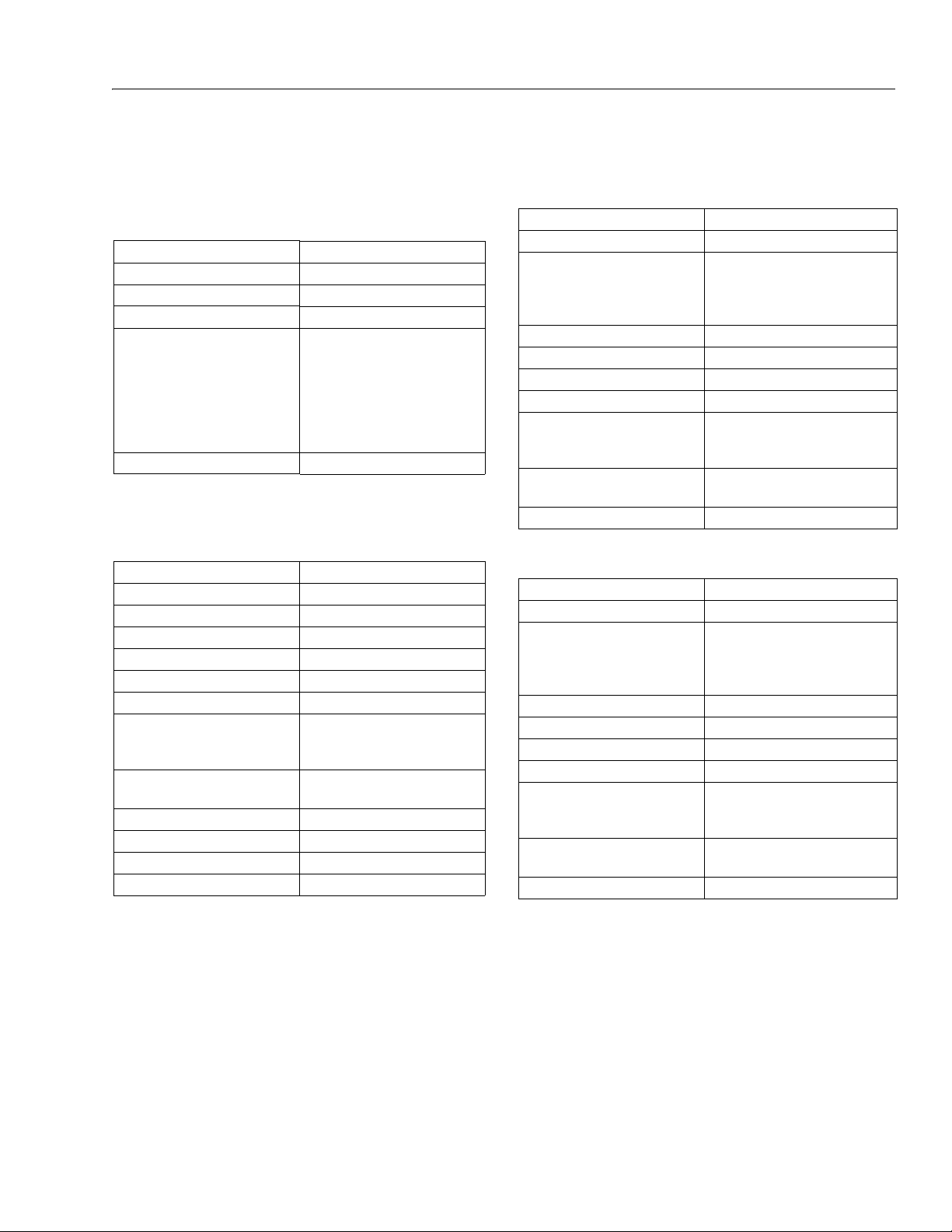
SECTION 1. SPECIFICATIONS
SECTION 1 - SPECIFICATIONS
1.1 CAPACITIES
Table 1-1. Capacities
Fuel Tank Approx. 39 gallons (147.6 liters)
Hydraulic Tank Approx. 40 gallons (151.4 liters)
Hydraulic System (Including Tank) 77 Gal. (291.4 L)
Drive Hub 17 ounces (0.50 L)
Engine Oil Capacity
F or d
D eu t z
C o ol i ng S ys t e m
C r an k ca s e
To t al C ap a c it y
G M
Air Compressor 4 qts. (3.8 L)
4.5 Quar ts (4.25 L) w/Filter
5 Quarts (4.5 L)
11 Quarts (10.5 L) w/Filter
16 Quarts (15 L)
4.5 Quar ts (4.25 L) w/Filter
1.2 ENGINE DATA
Table 1-2. Ford LRG-425 Specifications
Ty pe Wa t er -c oo led
Fuel Gasoline
Oil Capacity 4.5 Quar ts (4.25 L) w/Filter
Idle RPM 1000
Low RPM 1800
High RPM 2800
Alternator 95 Amp, Belt Drive
Fuel Consumption
L ow R P M
H ig h R PM
Battery 1000 Cold Cranking Amps, 210
minute reserve Capacity, 12 VDC
Horsepower 74 @ 3000 RPM, full load
Cooling System 16 Quarts (15.14 L)
Spark Plug AWSF-52-C
Spark Plug Gap 0.044 in. (1.117 mm)
3.45 GPH (13.06 lph)
4.60 GPH (17.41 lph)
Type Liquid Cooled (Oil)
Fuel Diesel
Oil Capacity
C oo l i ng S ys t em
Crankcase
To t al C ap a ci t y
Idle RPM 1000
Low RPM 1800
High RPM 2800
Alternator 55 Amp, belt drive
Fuel Consumption
L ow R P M
H ig h R PM
Battery 1000 Cold Cranking Amps, 210
Horsepower 65 @ 3000 RPM, full load
Type Liquid Cooled (Oil)
Fuel Diesel
Oil Capacity
C oo l i ng S ys t em
Crankcase
To t al C ap a ci t y
Idle RPM 1000
Low RPM 1800
High RPM 2600
Alternator 55 Amp, belt drive
Fuel Consumption
L ow R P M
H ig h R PM
Battery 1000 Cold Cranking Amps, 210
Horsepower 64 @ 2600 RPM, full load
Table 1-3. Deutz F4M2011F Specifications
5 Quar ts (4.5 L)
11 Quar ts (10.5 L) w/Filter
16 Quarts (15 L)
1.90 GPH (7.19 lph)
2.50 GPH (9.46 lph)
minutes Reserve Capacity, 12 VDC
Table 1-4. Deutz D2011L04 Specifications
5 Quar ts (4.5 L)
11 Quar ts (10.5 L) w/Filter
16 Quarts (15 L)
1.90 GPH (7.19 lph)
2.50 GPH (9.46 lph)
minutes Reserve Capacity, 12 VDC
3121160 – JLG Lift – 1-1
Page 22

SECTION 1 - SPECIFICATIONS
Table 1-5. GM 3.0L
Fuel Gasoline or Gasoline/LP Gas
No. of Cylinders 4
BHP
G as o l in e
L P
Bore 4.0 in. (101.6 mm)
Stroke 3.6 in. (91.44 mm)
Displacement 181 cu.in. (3.0 L, 2966 cc)
Oil Capacity w/filter 4.5 qts. (4.25 L)
Minimum Oil Pressure
a t i d l e
H ot
Compression Ratio 9.2:1
Firing Order 1-3-4-2
Max. RPM 2800
18 psi (1.2 Bar) @ 2000 rpm
83 hp @ 3000 rpm
75 hp @ 3000 rpm
6 psi (0.4 Bar) @ 1000 rpm
1.3 TIRES
Table 1-6. Tire Specifications
Ply
Size Type
IN 445/55D 19.5 pneumatic 16 H 85 PSI
IN 445/55D 19.5 foam-filled 16 H N/A
Rating
Load
Range
Pressure
(6.0 Bar)
1.4 DRIVE SYSTEM
Table 1-7. Drive System
Drive Motor
Displacement
Drive Hub Ratio 9.3:1
Drive Brake Automatic spring applied, hydraulically
2.74 cu. in. max. 1.000 cu. in. min.
3
( 46 c m
max. 16.4 cm3 min.)
released disc brakes
1.5 SWING SYSTEM
Table 1-8. Swing System Specifications
Swing Motor Displacement
Swing Brake Automatic spring applied hydraulically
Swing Hub Ratio 50:1
4.9 cu. in. (80 cm
released disc brakes
1.6 HYDRAULIC DRIVE PUMP
Table 1-9. Hydraulic Drive Pump Specifications
Pump Output 35.5 GPM (134 lpm) @ 2800 RPM
Pump Displacement
Charge Pump Displacement
Charge Pump Output 9.5 GPM (37 lpm) @ 2800 RPM
Charge Pump Pressure 400 PSI. (27.5 Bar)@ 2800 RPM
2.8 cu. in. (46 cm3)
0.85 cu. in. (14 cm
Clockwise Rotation
1.7 VARIABLE DISPLACEMENT PUMP
Table 1-10. Variable Displacement Pump Specifications
Type Variable, swashplate design
Nominal Pressure 3600 psi (248 bar)
Peak Pressure 4600 psi (317 bar)
Pump Circuit Open
Displacement Vgmax
Pressure and Flow Control DFR1
Rotation Clockwise
NBR seals Nitrile rubber to DIN IS O 1629
Shaft SAE 1.00 in. (2.54 cm) splined
2.75 in
3
(45 cm3)
1.8 HYDRAULIC LOAD SENSE PUMP
Table 1-11. Hydraulic Load Sense Pump Specifications
Pump Displacement
Pump Output 15.5 GPM (59 lpm) @ 1800 RPM
Stand By Pressure 400 PSI.(27.5 Bar) @ 1800 RPM
High Pressure Relief High Pressure Relief - 2700 PSI.(186
Rotation Clockwise
2.1cu. in. (34.4 cm
3
) Max.
Bar)
3
)
3
)
1-2 – JLG Lift – 3121160
Page 23

SECTION 1 - SPECIFICATIONS
Table 1-12. Auxiliary Power Pump Specifications
Pump Output 2.1 GPM (9.5 lpm) @ 1400 PSI. (69
BAR)
Pump Displacement
0.305 cu. in. (5 cm
3
)
Valving Non-Adj. Unloader Preset to 230 psi
A d ju s ta b le R el i ef S e t a t 18 0 0 p s i .
Motor 12 V.D.C. 2T Extended EMC Protected
Intermittent Duty
Rotation Counterclockwise
Table 1-13. Hydraulic FIlter Specifications
Return Filter 10 Microns Absolute
Charge Filter 10 Microns Absolute
Hydraulic Strainers (In Tank) 30 Microns
Table 1-14. Compressor Specifications
Type Single Stage, Rotary Screw
Capacity 40 cfm (1.13 cu. meters)
Air Inlet System Dry Type Single Stage
Inlet Control Load / Unload
Cooling System Air to Oil
Ambient Operating Range -20 to +100°F (-29 to 38°C)
Table 1-15. Dimensional Data
Turning Radius (Outside) 14 ft.- 6 in. (4.42 m)
Turning Radius (Inside) 11 ft.- 0 in. (2.13 m)
Boom Elevation - 740A
A bo v e Gr a de
B el o w Gr a de
+80 ft.-3 in. (24.46 m)
-15 ft.-7 in. (4. 75 m)
Boom Elevation - 740AJ
A bo v e Gr a de
B el o w Gr a de
+80 ft.-3 in. (24.46 m)
-13 ft.- 1 in. (3.99 m)
Machine Height Stowed 9 ft. 9.5 in.(2.98 m)
Machine Length (Stowed) 36 ft.-6 in. (11.13 m)
Machine Width 8 ft.-0 in . (2.44 m)
Wheelbase 10 ft.- 0 in. (3.05 m)
Table 1-16. Operating Specifications
Maximum Work Load (Capacity)
Un r es tr i ct e d: 5 0 0 l b (2 3 0 k g)
Maximum Travel Grade
with boom in
stowed position (Gradeability) 4WD
45%
Maximum Travel Grade
with boom in
stowed position (Side Slope)
5°
Maximum Vertical Platform Height: 74 ft. (22.5 m)
Maximum Horizontal Platfor m Reach 51 ft. 10 in. (15.8 m)
Ground Clearance 12 in. (30 cm)
Wheelbase 10 ft. (3.05 m)
Maximum Tire Load: 17,755 lbs. (8060 kg)
Maximum Drive Speed: 3.0 mph (4.8 kph)
Maximum Hyd. Operating Pressure 4500 psi (310 Bar)
Electrical System Voltage 12 volts
Jet Blast Rating 90 mph (145 kph)
Max. Ground Bearing Pressure
84 psi (5.3 kg/cm
3
)
Gross Machine Weight 39,200 lb. (17,780 kg)
1.9 AUXILIARY POWER PUMP
1.10 HYDRAULIC FILTER - IN-LINE
1.11 COMPRESSOR
1.12 DIMENSIONAL DATA
1.13 OPERATING SPECIFICATIONS
3121160 – JLG Lift – 1-3
Page 24
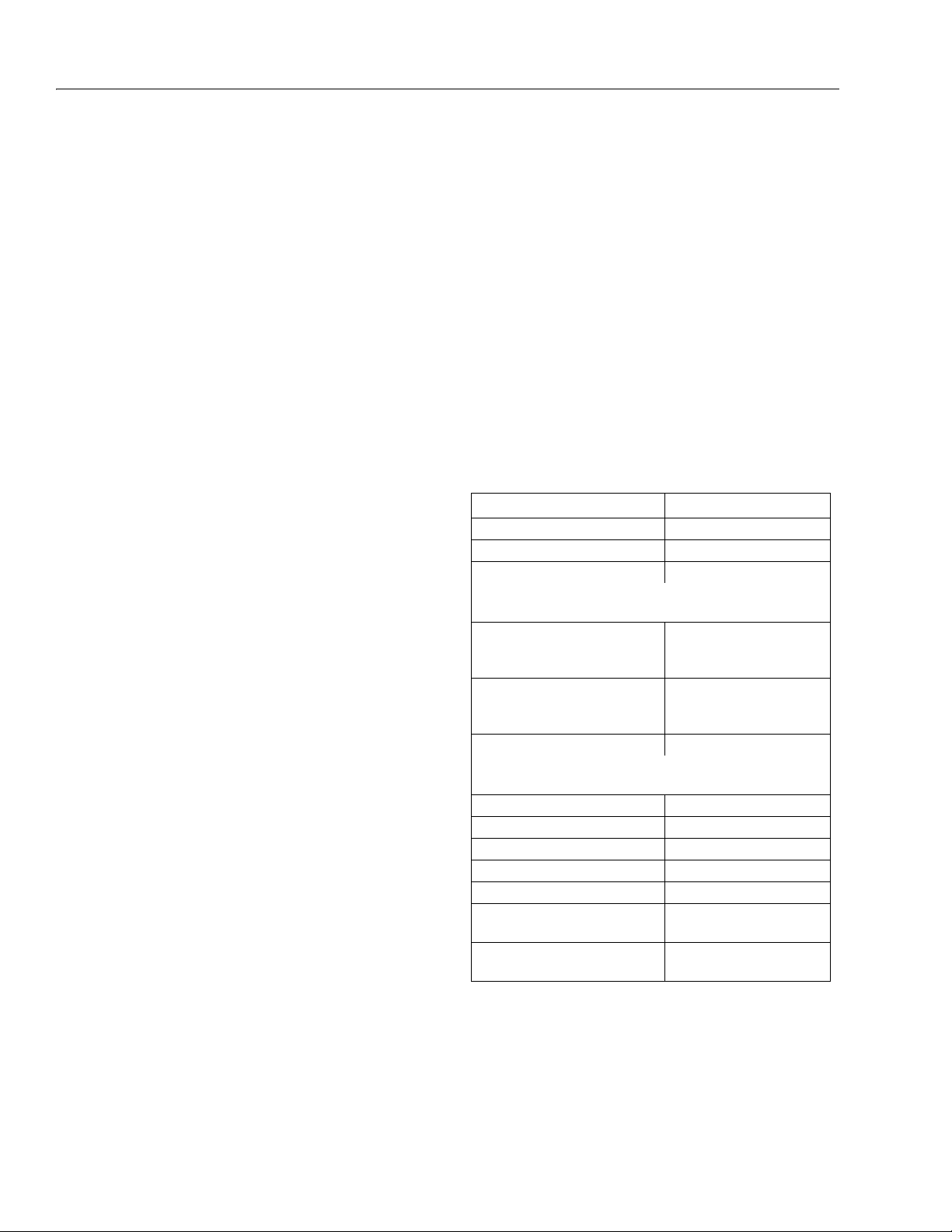
SECTION 1 - SPECIFICATIONS
Table 1-17. Function Speeds
Function Speed (In Seconds)
Main Lift Up 45 - 50
Main Lift Down 45 - 50
Swing Right & Left 79 - 101
NOTE: No more than 10% difference between swing left
and swing right.
Main Telescope In
800A
800AJ
30-40
24-34
Main Telescope Out
800A
800AJ
35-45
30-40
Platform Rotate Right & Left 19 - 30
NOTE: No more that 15% difference between rotator left
and rotator right.
Jib Up & Down 16-22
Tower Lift Up 57 - 70
Tower Lift Down 44 - 53
Drive (2WD) Forward & Reverse 33-45
Drive (4WD) Forward & Reverse 33-45
Drive Above Elevation
2WD Forward & Reverse Min 61
Drive Above Elevation
4WD Forward & Reverse Min 122
4150241-D
1.14 FUNCTION SPEEDS
Machine Orientation When Doing Speed Tests
To w e r L i f t : Upper Boom Horizontal, Telescoped In. Tower
Lift Up, Record Time. Tower Lift Down, Record Time.
Lift: Tower Lift Fully Elevated, Tower Telescope Fully
Extended, Main Telescope Fully Retracted.
Swing: Boom at Full Elevation. Telescope Retracted.
Swing the Turntable off center and stop. Swing the opposite direction and start the test when the turntable is centered up. This eliminates ramp up and down on the
controller affecting times.
Te l es c o pe : Boom at Full Elevation; Telescope Retracted;
Telescope Out, Record Time. Telescope In, Record Time.
Drive (Forward/Reverse): Test should be done on a
smooth level surface. Drive Select Switch should be set to
High Engine. Start approximately 25 ft. (7.62 m) from the
starting point so that the unit is at maximum speed when
starting the test. Results should be recorded for a 200 ft.
(60.96 m) course. Drive Forward, Record Time. Drive
Reverse, Record Time.
Drive (Above Horizontal): Test should be done on a
smooth, level surface. Drive Select Switch should be set to
Low Engine, Low Drive. The Platform Speed Knob control
should be positioned to Creep Speed. This simulates
machine speed when the boom is above horizontal.
Results should be recorded for a 50 ft. (15.2 m) course.
Drive Forward, Record Time. Drive Reverse, Record Time.
Platform Rotate: Platform level and completely rotated
one direction. Rotate the opposite direction, Record Time.
Rotate the other direction, Record Time.
Articulating Jib: Platform level and centered with the
boom. Start with the Jib down. Jib Up, Record Time. Jib
Down, Record Time.
1-4 – JLG Lift – 3121160
Test No tes
1. Stop watch should be started with the function, not
with the controller or switch.
2. Drive test results reflect 15x19.5 or 18x19.5 tires,
pneumatic or foam filled.
3. All speed tests are run from the platform. These
speeds do not reflect the ground control operation.
4. The platform speed knob control must be at full
speed (turned clockwise completely).
5. Function speeds may vary due to cold, thick hydraulic oil. Test should be run with the oil temperature
above 100° F (38° C).
6. Some flow control functions may not work with the
speed knob clicked into the creep position.
Page 25
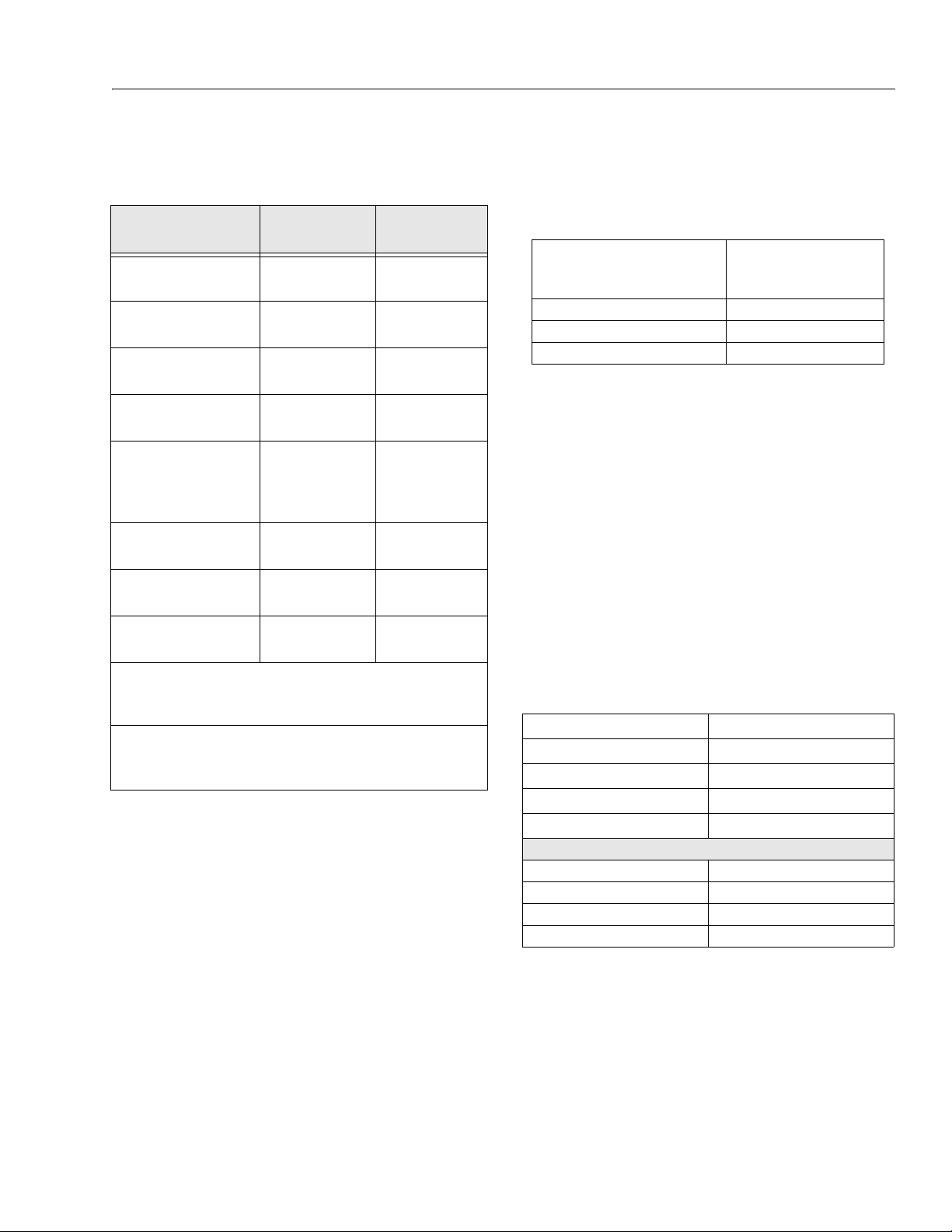
SECTION 1 - SPECIFICATIONS
1.15 TORQUE REQUIREMENTS
Wheel Bolts 300 ft. lbs.
Support to Rotator Bolts 50 ft. lbs.
Rotator Center Bolt 480 ft.lbs.
Swing Bearing Bolts 190 ft. lbs.
Star ter or Aux Pump
Solenoid
C on t a ct s
C oi l
Oxygen Sensor (Ford
Engine)
Megajector Mounting
Bolts (Ford Engine)
Lockoff Solenoid (Ford
Engine)
*Check swing bearing bolts for security after first 50 hours
of operation and every 600 hours thereafter. (See Swing
NOTE: When maintenance becomes necessary or a fas-
Table 1-18. Torque Requirements
Description
tener has loosened, refer to the Torque Chart to
determine proper torque value.
Torque Va l u e
(Dry)
(407 Nm)
(68 Nm)
(651 Nm)
(260 Nm)
95 in. lbs. (10.5 Nm)
40 in. lbs. (4.5 Nm)
29.5-40 ft. lbs.
(40-54 Nm)
60 in. lbs.
(7 Nm)
8-12 ft.lbs.
(11-16 Nm)
Bearing in Section 3.)
Interval Hours
150
As required
As required
50/600*
As required
At Installation
As required
At Installation
1.16 LUBRICATION
Hydraulic Oil
Table 1-19. Hydraulic Oil
Hydraulic System
Operating
Temperature Range
+0° to + 180° F (-18° to +83° C) 10W
+0° to + 210° F (-18° to +99° C) 10W-20, 10W30
+50° to + 210° F (+10° to +99° C 20W-20
NOTE: Hydraulic oils must have anti-wear qualities at least
to API Service Classification GL-3, and sufficient
chemical stability for mobile hydraulic system service. JLG Industries recommends Mobilfluid 424
hydraulic oil, which has an SAE viscosity index of
152.
NOTE: When temperatures remain consistently below 20
degrees F. (-7 degrees C.), JLG Industries recommends the use of Mobil DTE13.
Aside from JLG recommendations, it is not advisable to
mix oils of different brands or types, as they may not contain the same required additives or be of comparable viscosities. If use of hydraulic oil other than Mobilfluid 424 is
desired, contact JLG Industries for proper recommendations.
Table 1-20. Mobilfluid 424 Specs
SAE Grade 10W30
Gravity, API 29.0
Density, Lb/Gal. 60°F 7.35
Pour Point, Max -46°F (-43°C)
Flash Point, Min. 442°F (228°C)
Viscosity
Brookfield, cP at -18°C 2700
at 40° C 55 cSt
at 100° C 9.3 cSt
Viscosity Index 152
S.A.E. Viscosity
Grade
3121160 – JLG Lift – 1-5
Page 26
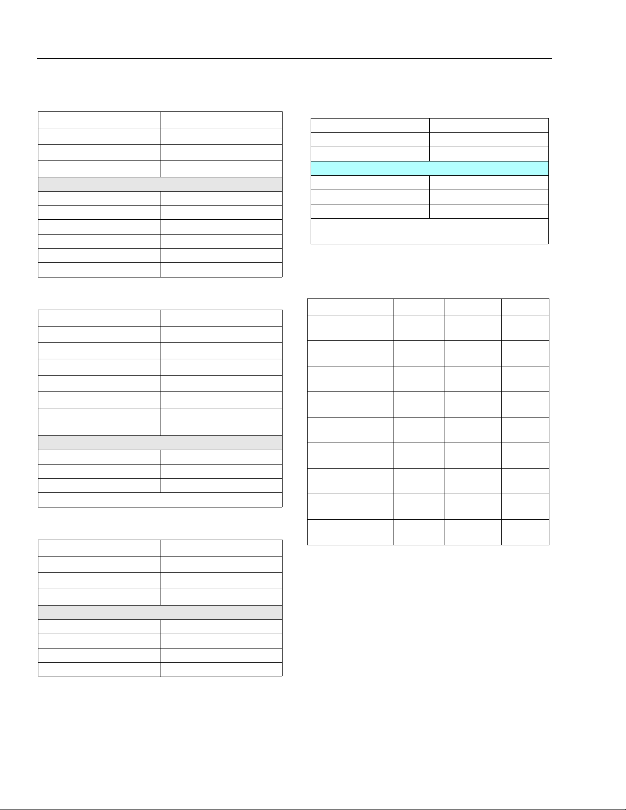
SECTION 1 - SPECIFICATIONS
Table 1-24. Exxon Univis HVI 26 Specs
Specific Gravity 32.1
Pour Point -76°F (-60°C)
Flash Point 217°F (103°C)
Viscosity
at 40° C 25.8 cSt
at 100° C 9.3 cSt
Viscosity Index 376
NOTE: Mobil/Exxon recommends that this oil be
checked on a yearly basis for viscosity.
Table 1-25. Cylinder Specifications
DESCRIPTION BORE STROKE ROD DIA.
Lower Lift
8.00
(203.2)
49.38
(1254.1)
3.00
(76.2)
Upright Level
8.00
(203.6)
42.00
(1066.8)
3.50
(88.9)
Upper Lift
8.00
(203.2)
28.75
(730.3)
3.50
(88.9)
Upper Telescope
3.50
(88.9)
206.5
(5245.1)
2.75
(69.9)
Steer
3.00
(76.2)
10.75
(273.1)
1.50
(38.1)
Lockout
4.00
(101.6)
3.88
(98.4)
1.50
(38.1)
Master
3.50
(88.9)
18.50
(469.9)
1.50
(38.1)
Slave
3.50
(88.9)
17.50
(444,5)
1.50
(38.1)
Lift (Jib)
3.00
(76.2)
25.50
(647.7)
1.50
(38.1)
Table 1-21. Mobil DTE 13M Specs
ISO Viscosity Grade #32
Specific Gravity 0.877
Pour Point, Max -40°F (-40°C)
Flash Point, Min. 330°F (166°C)
Viscosity
at 40° C 33cSt
at 100° C 6.6 cSt
at 100° F 169 SUS
at 210° F 48 SUS
cp at -20° F 6,200
Viscosity Index 140
Table 1-22. Mobil EAL 224H Specs
Type Synthetic Biodegradable
ISO Viscosity Grade 32/46
Specific Gravity .922
Pour Point, Max -25°F (-32°C)
Flash Point, Min. 428°F (220°C)
Operating Temp. 0 to 180°F (-17 to 162°C)
Weight
Viscosity
at 40° C 37 cSt
at 100° C 8.4 cSt
Viscosity Index 213
NOTE: Must be stored above 32°F (14°C)
7.64 lb. per gal.
(0.9 kg per liter)
1.17 CYLINDER SPECIFICATIONS
Table 1-23. UCon Hydrolube HP-5046
1-6 – JLG Lift – 3121160
Type Synthetic Biodegradable
Specific Gravity 1.082
Pour Point, Max -58°F (-50°C)
at 0° C (32° F) 340 cSt (1600SUS)
at 40° C (104° F) 46 cSt (215SUS)
at 65° C (150° F) 22 cSt (106SUS)
Viscosity Index 170
pH 9.1
Viscosity
Page 27
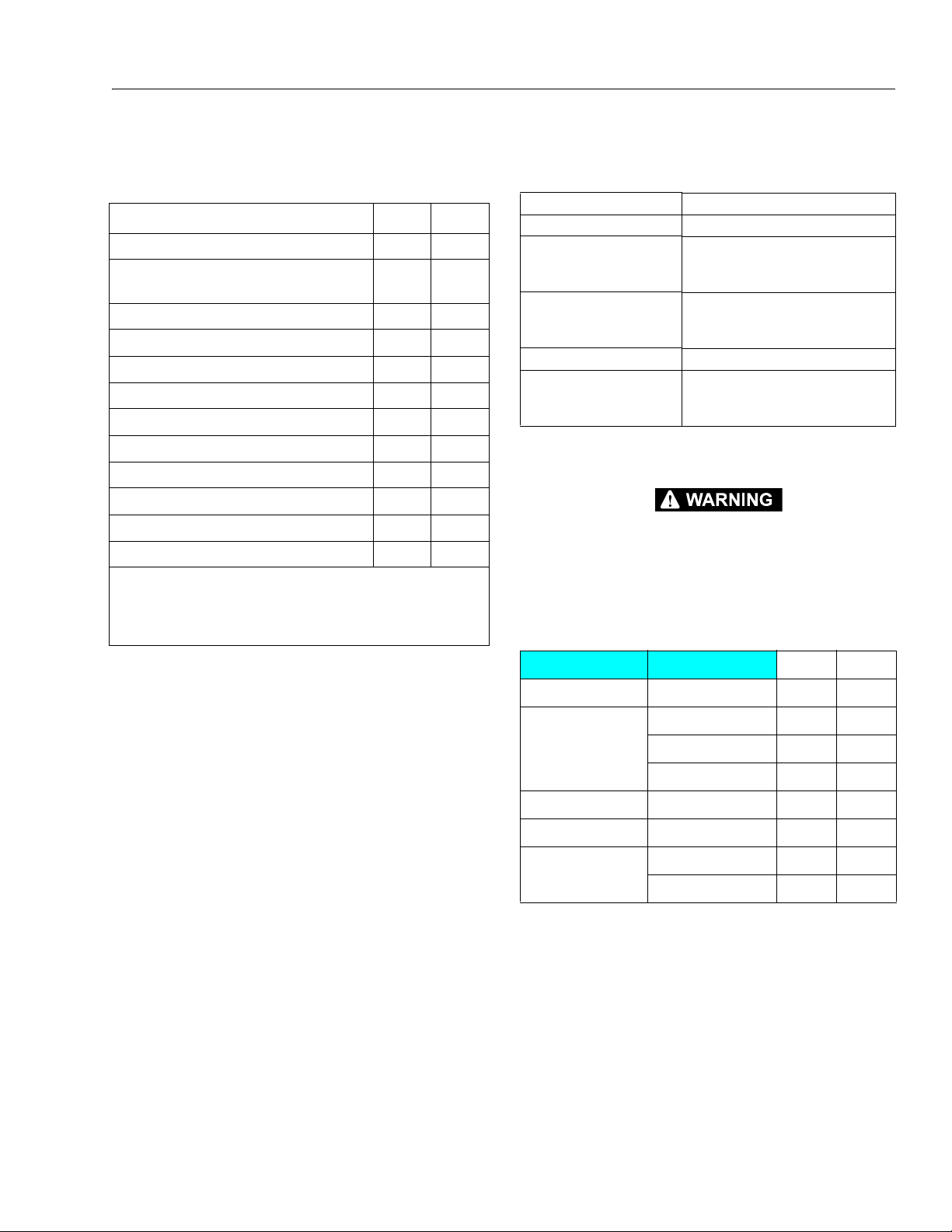
SECTION 1 - SPECIFICATIONS
1.18 MAJOR COMPONENT WEIGHTS 1.19 PRESSURE SETTINGS
Table 1-26. Major Component Weights - 800AJ
MAJOR COMPONENTS LBS. KG.
Platform & Control Console 250 113
Main Boom (Inc. Slave Cylinder Rotator, And
Support)
Main Lift Cylinder 500 230
Main Telescope Cylinder 480 220
Upright 1175 535
Upright Level Cylinder 585 265
Tower Boom Complete 3450 1565
To we r Li f t C y li nd e r 6 25 2 85
Turntable Counterweight 4805 2180
Turntable Complete (Including Engine) 11025 5001
Chassis Complete 12620 5724
Machine Complete (GVW) 33100 15020
NOTE: The above components are separate assemblies.
example: "TURNTABLE COMPLETE" does not include
booms, upright, lift cylinders or platform. The weights of
these components must be added for the total weight.
3185 1445
Upper boom Lift Down Relief 1400 PSI. (97 Bar)
Swing Relief 1400 PSI. (97 Bar)
Platform Level Relief:
U p
D ow n
Steer Relief
2 WS
4 WS
Tower Boom Telescope 2200 PSI. (151.7 Bar)
Articulating Jib Boom
U p
D ow n
1.20 CRITICAL STABILITY WEIGHTS
DO NOT REPLACE ITEMS CRITICAL TO STABILITY WITH ITEMS
OF DIFFERENT WEIGHT OR SPECIFICATION (FOR EXAMPLE:
BATTERIES, FILLED TIRES, COUNTER WEIGHT, ENGINE, AND
PLATFORM) DO NOT MODIFY UNIT IN ANY WAY TO EFFECT STABILITY.
Table 1-27. Pressure Settings
Table 1-28. Critical Stability Weights
2800 PSI. (193 Bar)
1800 PSI. (124 Bar)
1800 PSI. (124.11Bar)
2500 PSI. (172 Bar)
2500 PSI. (172 Bar)
1200 PSI. (83 Bar)
COMPONENTS LBS. KG.
Tire & Wheel
Engine Ford
Counterweight Turntable
Wheel Hubs Front & Rear
Platform 6 FT. (1.83 M)
18 X 19.5
Deutz
GM w/pumps
8 FT. (2.44 M)
675 305
600 209
534 242
1030 468
4805 2180
218 99
205 93
230 105
3121160 – JLG Lift – 1-7
Page 28
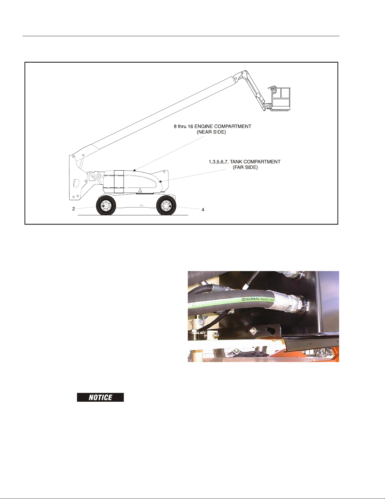
SECTION 1 - SPECIFICATIONS
Figure 1-1. Operator Maintenance and Lubrication Diagram
1.21 OPERATOR MAINTENANCE
NOTE: The following numbers correspond to those in Fig-
ure 1-1., Operator Maintenance and Lubrication
Diagram.
Table 1-29. Lubrication Specifications
KEY SPECIFICATIONS
MPG Multipurpose Grease having a minimum dripping point of 350° F
(177° C). Excellent water resistance and adhesive qualities, and
being of extreme pressure type.
(Timken OK 40 pounds minimum.)
EPGL Extreme Pressure Gear Lube (oil) meeting API service classifi-
c at io n G L-5 or MI L-S pe c MI L-L- 21 05
HO Hydraulic Oil. API service classification GL-3, e.g. Mobilfluid
424.
EO Engine (crankcase) Oil. Gas - AP I SF, SH, SG class, MIL-L-2104.
Diesel - API CC/CD class, MIL-L-2104B/MIL-L-2104C.
LUBRICATION INTERVALS ARE BASED ON MACHINE OPERATION
UNDER NORMAL CONDITIONS. FOR MACHINES USED IN MULTISHIFT OPERATIONS AND/OR EXPOSED TO HOSTILE ENVIRONMENTS OR CONDITIONS, LUBRICATION FREQUENCIES MUST BE
INCREASED ACCORDINGLY.
NOTE: It is recommended as a good practice to replace all
filters at the same time.
1. Swing Bearing - Internal Ball Bearing
Lube Point(s) - 2 Grease Fittings
Capacity - A/R
Lube - MPG
Interval - Every 3 months or 150 hrs of operation
Comments - Remote Access
1-8 – JLG Lift – 3121160
Page 29
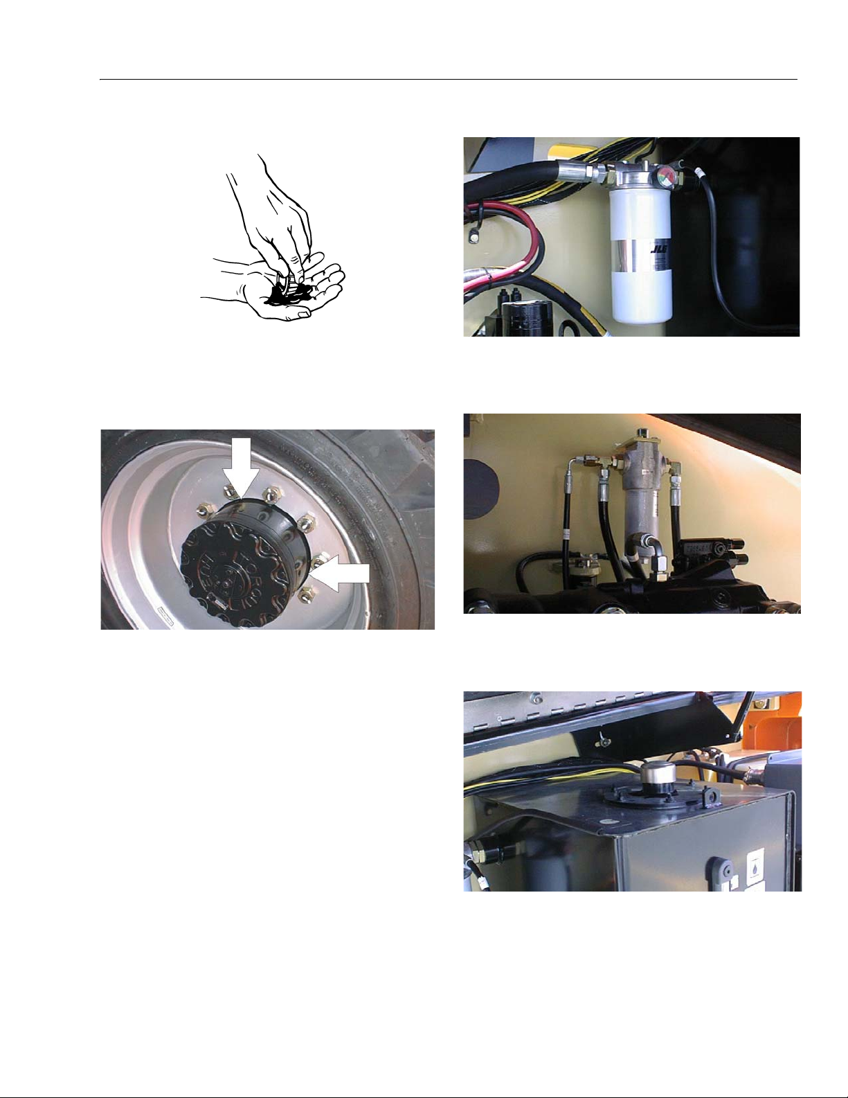
SECTION 1 - SPECIFICATIONS
2.Wheel Bearings
Lube Point(s) - Repack
Capacity - A/R
Lube - MPG
Interval - Every 2 years or 1200 hours of operation
3.Wheel Drive Hub
4.Hydraulic Return Filter
Interval - Change after first 50 hrs. and every 6
months or 300 hrs. thereafter or as indicated by
Condition Indicator.
5.Hydraulic Charge Filter
Lube Point(s) - Level/Fill Plug
Capacity - 17 oz. (0.5 L) - 1/2 Full
Lube - EPGL
Interval - Check level every 3 months or 150 hrs of
operation; change every 2 years or 1200 hours of
operation
Comments - Place Fill port at 12 o’clock position
and Check port at 3 o’clock position. Pour lubricant into fill port until it just starts to flow out of
check port.
Interval - Change after first 50 hrs. and every 6
months or 300 hrs. thereafter or as indicated by
Condition Indicator.
6.Hydraulic Tank
Lube Point(s) - Fill Cap
Capacity - 40 gallons (151 L) Tank; 77 gallons
(291.4 L) System
Lube - HO
Interval - Check Level daily; Change every 2 years
or 1200 hours of operation.
3121160 – JLG Lift – 1-9
Page 30
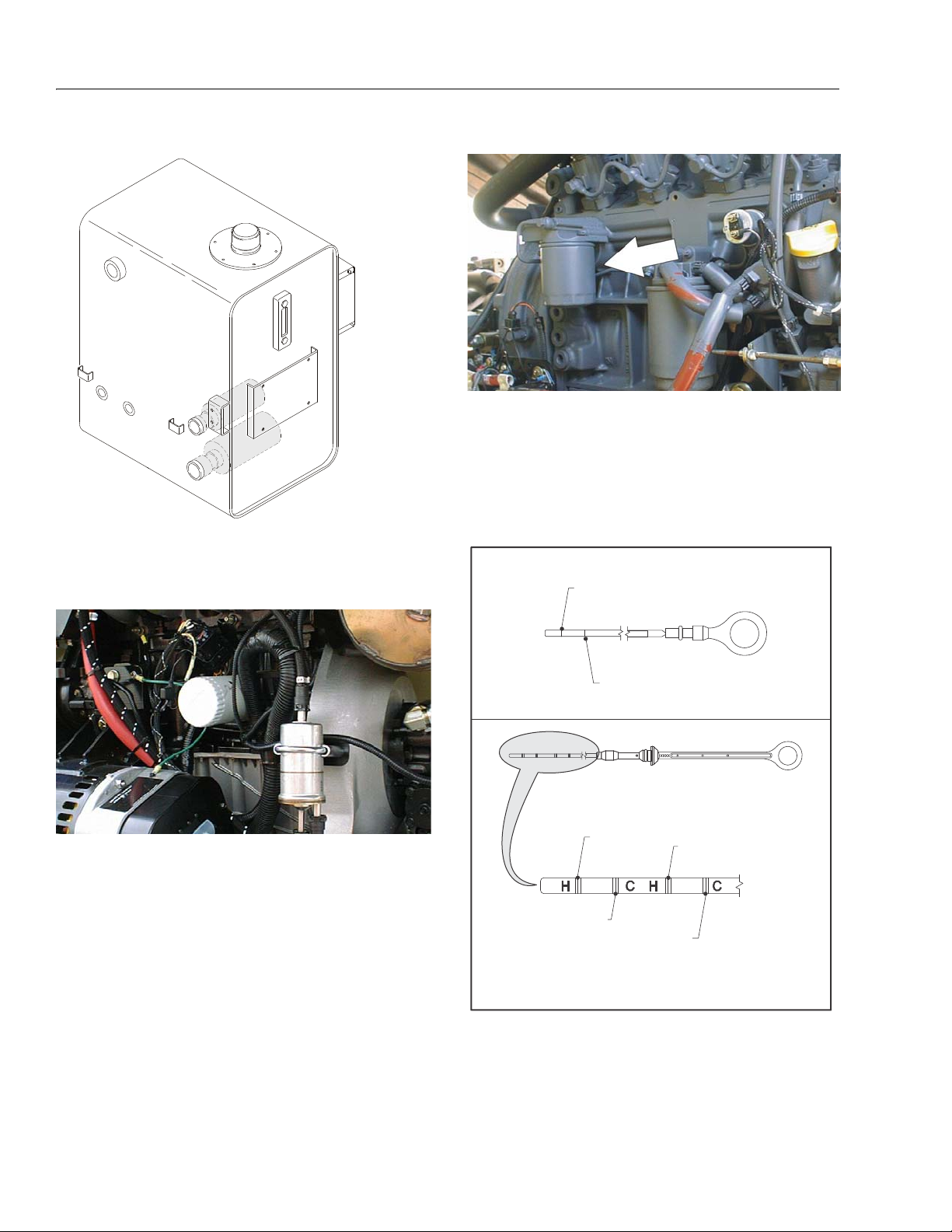
SECTION 1 - SPECIFICATIONS
MINIMUM LEVEL,
OIL HOT
MINIMUM OIL
LEVEL
MINIMUM LEVEL,
OIL COLD
NOTE: Hot oil checks should not be made until the engine
has been shut down for a period of 5 minutes.
MAXIMUM LEVEL,
OIL HOT
MAXIMUM LEVEL,
OIL COLD
MAXIMUM OIL
LEVEL
Figure 1-2. Deutz Engine Dipstick
7.Suction Strainers
Lube Point(s) - 2
Interval - Every 2 years or 1200 hours of operation,
remove and clean at time of hydraulic oil change.
9.Oil Change w/Filter - Deutz
Lube Point(s) - Fill Cap/Spin-on Element
Capacity - 11 Quarts(10.5 L) Crankcase
Lube - EO
Interval - Every Year or 1200 hours of operation
Comments - Check level daily/Change in accordance with engine manual. Refer to Figure 1-2.,
Deutz Engine Dipstick.
8.Oil Change w/Filter - Ford
Lube Point(s) - Fill Cap/Spin-on Element
Capacity - 4.5 Quarts
Lube - EO
Interval - 3 Months or 150 hours of operation
Comments - Check level daily/Change in accordance with engine manual.
1-10 – JLG Lift – 3121160
Page 31

SECTION 1 - SPECIFICATIONS
10. Oil Change w/Filter - GM
Lube Point(s) - Fill Cap/Spin-on Element
(JLG P/N 7027965)
Capacity - 4.5 qt. (4.25 L) w/filter
Lube - EO
Interval - 3 Months or 150 hours of operation
Comments - Check level daily/Change in accordance with engine manual.
11.Fuel Filter - Ford
13.Fuel Filter (Gasoline) - GM
Lube Point(s) - Replaceable Element
Interval - Every 6 months or 300 hours of operation
14.Air Filter
Lube Point(s) - Replaceable Element
Interval - Every 6 months or 300 hours of operation
or as indicated by the condition indicator
15.Electronic Pressure Regulator (LP only)
Lube Point(s) - Replaceable Element
Interval - Every Year or 1200 hours of operation
12.Fuel Filter - Deutz
Lube Point(s) - Replaceable Element
Interval - Every Year or 600 hours of operation
Interval - 3 Months or 150 hours of operation
Comments - Drain oil build up. Refer to Draining
Oil Build Up From The Propane Regulator
16.Fuel Filter (Propane) - GM Engine
Interval - 3 Months or 150 hours of operation
Comments - Replace filter. Refer to Propane Fuel
Filter Replacement
3121160 – JLG Lift – 1-11
Page 32

SECTION 1 - SPECIFICATIONS
Draining Oil Build Up From The Propane Regulator
During the course of normal operation oils may build
inside the primary and secondary chambers of the propane pressure regulator. These oils may be a result of
poor fuel quality, contamination of the fuel supply
chain, or regional variation in the make up of the fuel. If
the build up of the oil is significant this can effect the
operation of the fuel control system. Refer to Section
1.21, Operator Maintenance for maintenance intervals.
More frequent draining may be required if the fuel supply has been contaminated.
FOR BEST RESULTS WARM THE ENGINE TO OPERATING TEMPERATURE BEFORE DRAINING. THIS WILL ALLOW THE OILS TO
BE LIQUID AND FLOW FREELY FROM THE REGULATOR.
1. Move the equipment to a well ventilated area.
Ensure there are no external ignition sources.
2. Start the engine and bring to operating temperature.
3. With the engine running, close the manual tank
valve and run the engine out of fuel.
4. Push in the Emergency Switch once the engine
stops.
5. Disconnect the electrical connection to the LPG fuel
temperature sensor in the auxiliary fuel port of the
EPR.
6. Remove the retainer clip for the LPG fuel temperature sensor and remove the sensor from the regulator body.
NOTE: Have a small container ready to collect oil that will
drain freely from the regulator at this point.
7. Once all of the oil has been drained, reinstall the
LPG fuel temperature sensor and reconnect the
electrical connector.
8. Open the fuel tank manual valve.
9. Start the engine and verify all connections are
secure.
10. Dispose of any drained oil in a safe and proper fashion.
1-12 – JLG Lift – 3121160
Page 33

Propane Fuel Filter Replacement
11
2
13
33
44
55
6
77
88
99
OR
10 10
11
11
12
1. Electric Lock Off Solenoid
2. Mounting Plate
3. Housing Seal
4. Filter Magnet
5. Filter Housing
6. Seal
7. Electrical Connector
8. Fuel Outlet
9. O-ring
10. Filter
11. Fuel Inlet
12. Retaining Bolt
Figure 1-3. Filter Lock Assembly
SECTION 1 - SPECIFICATIONS
REMOVAL
INSTALLATION
1. Relieve the propane fuel system pressure. Refer to
Propane Fuel System Pressure Relief.
2. Disconnect the negative battery cable.
BE SURE TO REINSTALL THE FILTER MAGNET INTO THE HOUSING BEFORE INSTALLING NEW SEAL
3. Slowly loosen the Filter housing retaining bolt and
remove it.
4. Pull the filter housing from the Electric lock off
assembly .
5. Locate Filter magnet and remove it.
6. Remove the filter from the housing.
7. Remove and discard the housing seal.
8. Remove and discard the retaining bolt seal.
9. Remove and discard mounting plate to lock off O-
ring seal.
1. Install the mounting plate to lock off O-ring seal.
2. Install the retaining bolt seal.
3. Install the housing seal.
4. Drop the magnet into the bottom of the filter hous-
ing.
5. Install the filter into the housing.
6. Install the retaining bolt into the filter housing.
7. Install the filter up to the bottom of the electric lock
off.
8. Tighten the filter retaining bolt to 106 in lbs (12 Nm).
3121160 – JLG Lift – 1-13
9. Open manual shut-off valve. Start the vehicle and
leak check the propane fuel system at each serviced
fitting. Refer to Propane Fuel System Leak Test.
Page 34

SECTION 1 - SPECIFICATIONS
Propane Fuel System Pressure Relief
THE PROPANE FUEL SYSTEM OPERATES AT PRESSURES UP TO
312 PSI (21.5 BAR). TO MINIMIZE THE RISK OF FIRE AND PERSONAL INJURY, RELIEVE THE PROPANE FUEL SYSTEM PRESSURE (WHERE APPLICABLE) BEFORE SERVICING THE PROPANE
FUEL SYSTEM COMPONENTS.
To relieve propane fuel system pressure:
1. Close the manual shut-off valve on the propane fuel
tank.
2.Start and run the vehicle until the engine stalls.
3.Turn the ignition switch OFF.
RESIDUAL VAPOR PRESSURE WILL BE PRESENT IN THE FUEL
SYSTEM. ENSURE THE WORK AREA IS WELL VENTILATED
BEFORE DISCONNECTING ANY FUEL LINE.
1-14 – JLG Lift – 3121160
Page 35

SECTION 1 - SPECIFICATIONS
Figure 1-4. Torque Chart (SAE Fasteners - Sheet 1 of 3)
3121160 – JLG Lift – 1-15
Page 36

SECTION 1 - SPECIFICATIONS
Figure 1-5. Torque Chart (SAE Fasteners - Sheet 2 of 3))
1-16 – JLG Lift – 3121160
Page 37

SECTION 1 - SPECIFICATIONS
Figure 1-6. Torque Chart (SAE Fasteners - Sheet 3 of 3)
3121160 – JLG Lift – 1-17
Page 38

SECTION 1 - SPECIFICATIONS
Figure 1-7. Torque Chart (METRIC Fasteners - Sheet 1 of 3)
1-18 – JLG Lift – 3121160
Page 39

SECTION 1 - SPECIFICATIONS
Figure 1-8. Torque Chart (METRIC Fasteners - Sheet 2 of 3))
3121160 – JLG Lift – 1-19
Page 40

SECTION 1 - SPECIFICATIONS
Figure 1-9. Torque Chart (METRIC Fasteners - Sheet 3 of 3)
1-20 – JLG Lift – 3121160
Page 41

SECTION 2. GENERAL
SECTION 2 - GENERAL
2.1 MACHINE PREPARATION, INSPECTION, AND MAINTENANCE
General
This section provides the necessary information needed
by those personnel that are responsible to place the
machine in operation readiness and maintain its safe
operating condition. For maximum service life and safe
operation, ensure that all the necessary inspections and
maintenance have been completed before placing the
machine into service.
Preparation, Inspection, and Maintenance
It is important to establish and conform to a comprehensive inspection and preventive maintenance program. The
following table outlines the periodic machine inspections
and maintenance recommended by JLG Industries, Inc.
Consult your national, regional, or local regulations for further requirements for aerial work platforms. The frequency
of inspections and maintenance must be increased as
environment, severity and frequency of usage requires.
Pre-Start Inspection
It is the User’s or Operator’s primary responsibility to perform a Pre-Start Inspection of the machine prior to use
daily or at each change of operator. Reference the Operator’s and Safety Manual for completion procedures for the
Pre-Start Inspection. The Operator and Safety Manual
must be read in its entirety and understood prior to performing the Pre-Start Inspection.
Pre-Delivery Inspection and Frequent Inspection
The Pre-Delivery Inspection and Frequent Inspection shall
be performed by a qualified JLG equipment mechanic.
JLG Industries, Inc. recognizes a qualified JLG equipment
mechanic as a person who, by possession of a recognized degree, certificate, extensive knowledge, training, or
experience, has successfully demonstrated the ability and
proficiency to service, repair, and maintain the subject
JLG product model.
The Pre-Delivery Inspection and Frequent Inspection procedures are performed in the same manner, but at different times. The Pre-Delivery Inspection shall be performed
prior to each sale, lease, or rental delivery. The Frequent
Inspection shall be accomplished for each machine in service for 3 months or 150 hours (whichever comes first);
out of service for a period of more than 3 months; or when
purchased used. The frequency of this inspection must be
increased as environment, severity and frequency of
usage requires.
Reference the JLG Pre-Delivery and Frequent Inspection
Form and the Inspection and Preventative Maintenance
Schedule for items requiring inspection during the performance of these inspections. Reference the appropriate
areas of this manual for servicing and maintenance procedures.
Annual Machine Inspection
The Annual Machine Inspection must be performed by a
Factory-Certified Service Technician on an annual basis,
no later than thirteen (13) months from the date of the
prior Annual Machine Inspection. JLG Industries, Inc. recognizes a Factory-Certified Service Technician as a person who has successfully completed the JLG Service
Training School for the subject JLG product model. Reference the machine Service and Maintenance Manual and
appropriate JLG inspection form for performance of this
inspection.
Reference the JLG Annual Machine Inspection Form and
the Inspection and Preventative Maintenance Schedule for
items requiring inspection during the performance of this
inspection. Reference the appropriate areas of this manual for servicing and maintenance procedures.
For the purpose of receiving safety-related bulletins, it is
important that JLG Industries, Inc. has updated ownership
information for each machine. When performing each
Annual Machine Inspection, notify JLG Industries, Inc. of
the current machine ownership.
Preventative Maintenance
In conjunction with the specified inspections, maintenance shall be performed by a qualified JLG equipment
mechanic. JLG Industries, Inc. recognizes a qualified JLG
equipment mechanic as a person who, by possession of a
recognized degree, certificate, extensive knowledge, training, or experience, has successfully demonstrated the
ability and proficiency to service, repair, and maintain the
subject JLG product model.
Reference the Preventative Maintenance Schedule and
the appropriate areas of this manual for servicing and
maintenance procedures. The frequency of service and
maintenance must be increased as environment, severity
and frequency of usage requires.
3121160 – JLG Lift – 2-1
Page 42

SECTION 2 - GENERAL
Table 2-1. Inspection and Maintenance
Type Frequency
Pre-Start Inspection
Pre-Delivery
Inspection
Frequent Inspec-
tion
Annual Machine
Inspection
Preventative
Maintenance
In service for 3 months or 150 hours, which-
Prior to use each day; or
At each Operator change.
Prior to each sale, lease, or
rental delivery.
ever comes first; or
Out of service for a period of more than 3
months; or
Purchased used.
Annually, no later than 13 months from the
date of the prior inspection.
At intervals as specified in the Service and
Maintenance Manual.
2.2 SERVICE AND GUIDELINES
General
The following information is provided to assist you in the
use and application of servicing and maintenance procedures contained in this book.
Safety and Workmanship
Your safety, and that of others, is the first consideration
when engaging in the maintenance of equipment. Always
be conscious of weight. Never attempt to move heavy
parts without the aid of a mechanical device. Do not allow
heavy objects to rest in an unstable position. When raising
a portion of the equipment, ensure that adequate support
is provided.
Cleanliness
1. The most important single item in preserving the
long service life of a machine is to keep dirt and foreign materials out of the vital components. Precautions have been taken to safeguard against this.
Shields, covers, seals, and filters are provided to
keep air, fuel, and oil supplies clean; however, these
items must be maintained on a scheduled basis in
order to function properly.
Primary
Responsibility
User or Operator User or Operator Operator and Safety Manual
Owner, Dealer, or User Qualified JLG
Owner, Dealer, or User Qualified JLG
Owner, Dealer, or User Factory-Certified
Owner, Dealer, or User Qualified JLG
2. At any time when air, fuel, or oil lines are disconnected, clear adjacent areas as well as the openings
and fittings themselves. As soon as a line or component is disconnected, cap or cover all openings to
prevent entry of foreign matter.
3. Clean and inspect all parts during servicing or maintenance, and assure that all passages and openings
are unobstructed. Cover all parts to keep them
clean. Be sure all parts are clean before they are
installed. New parts should remain in their containers until they are ready to be used.
Service
Qualification
Mechanic
Mechanic
Service Technician
Mechanic
Reference
Service and Maintenance
Manual and applicable JLG
inspection form.
Service and Maintenance
Manual and applicable JLG
inspection form.
Service and Maintenance
Manual and applicable JLG
inspection form.
Service and Maintenance
Manual
Components Removal and Installation
1. Use adjustable lifting devices, whenever possible, if
mechanical assistance is required. All slings (chains,
cables, etc.) should be parallel to each other and as
near perpendicular as possible to top of part being
lifted.
2. Should it be necessary to remove a component on
an angle, keep in mind that the capacity of an eyebolt or similar bracket lessens, as the angle between
the supporting structure and the component
becomes less than 90 degrees.
3. If a part resists removal, check to see whether all
nuts, bolts, cables, brackets, wiring, etc., have been
removed and that no adjacent parts are interfering.
2-2 – JLG Lift – 3121160
Page 43

SECTION 2 - GENERAL
Component Disassembly and Reassembly
When disassembling or reassembling a component, complete the procedural steps in sequence. Do not partially
disassemble or assemble one part, then start on another.
Always recheck your work to assure that nothing has been
overlooked. Do not make any adjustments, other than
those recommended, without obtaining proper approval.
Pressure-Fit Parts
When assembling pressure-fit parts, use an anti-seize or
molybdenum disulfide base compound to lubricate the
mating surface.
Bearings
1. When a bearing is removed, cover it to keep out dirt
and abrasives. Clean bearings in nonflammable
cleaning solvent and allow to drip dry. Compressed
air can be used but do not spin the bearing.
2. Discard bearings if the races and balls (or rollers)
are pitted, scored, or burned.
3. If bearing is found to be serviceable, apply a light
coat of oil and wrap it in clean (waxed) paper. Do not
unwrap reusable or new bearings until they are
ready to install.
4. Lubricate new or used serviceable bearings before
installation. When pressing a bearing into a retainer
or bore, apply pressure to the outer race. If the bearing is to be installed on a shaft, apply pressure to the
inner race.
Gaskets
Check that holes in gaskets align with openings in the
mating parts. If it becomes necessary to hand-fabricate a
gasket, use gasket material or stock of equivalent material
and thickness. Be sure to cut holes in the right location, as
blank gaskets can cause serious system damage.
Bolt Usage and Torque Application
1. Use bolts of proper length. A bolt which is too long
will bottom before the head is tight against its related
part. If a bolt is too short, there will not be enough
thread area to engage and hold the part properly.
When replacing bolts, use only those having the
same specifications of the original, or one which is
equivalent.
2. Unless specific torque requirements are given within
the text, standard torque values should be used on
heat-treated bolts, studs, and steel nuts, in accordance with recommended shop practices. (See
Torque Chart Section 1.)
Hydraulic Lines and Electrical Wiring
Clearly mark or tag hydraulic lines and electrical wiring, as
well as their receptacles, when disconnecting or removing
them from the unit. This will assure that they are correctly
reinstalled.
Hydraulic System
1. Keep the system clean. If evidence of metal or rubber particles are found in the hydraulic system, drain
and flush the entire system.
2. Disassemble and reassemble parts on clean work
surface. Clean all metal parts with non-flammable
cleaning solvent. Lubricate components, as
required, to aid assembly.
Lubrication
Service applicable components with the amount, type,
and grade of lubricant recommended in this manual, at
the specified intervals. When recommended lubricants are
not available, consult your local supplier for an equivalent
that meets or exceeds the specifications listed.
Battery
Clean battery, using a non-metallic brush and a solution of
baking soda and water. Rinse with clean water. After
cleaning, thoroughly dry battery and coat terminals with
an anti corrosion compound.
Lubrication and Servicing
Components and assemblies requiring lubrication and
servicing are shown in the Lubrication Chart in Section 1.
2.3 LUBRICATION AND INFORMATION
Hydraulic System
1. The primary enemy of a hydraulic system is contamination. Contaminants enter the system by various
means, e.g., using inadequate hydraulic oil, allowing
moisture, grease, filings, sealing components, sand,
etc., to enter when performing maintenance, or by
permitting the pump to cavitate due to insufficient
system warm-up or leaks in the pump supply (suction) lines.
2. The design and manufacturing tolerances of the
component working parts are very close, therefore,
even the smallest amount of dirt or foreign matter
entering a system can cause wear or damage to the
components and generally results in faulty operation. Every precaution must be taken to keep
hydraulic oil clean, including reserve oil in storage.
Hydraulic system filters should be checked,
cleaned, and/or replaced as necessary, at the speci-
3121160 – JLG Lift – 2-3
Page 44

SECTION 2 - GENERAL
fied intervals required in the Lubrication Chart in
Section 1. Always examine filters for evidence of
metal particles.
3. Cloudy oils indicate a high moisture content which
permits organic growth, resulting in oxidation or corrosion. If this condition occurs, the system must be
drained, flushed, and refilled with clean oil.
4. It is not advisable to mix oils of different brands or
types, as they may not contain the same required
additives or be of comparable viscosities. Good
grade mineral oils, with viscosities suited to the
ambient temperatures in which the machine is operating, are recommended for use.
NOTE: Metal particles may appear in the oil or filters of new
machines due to the wear-in of meshing components.
Hydraulic Oil
1. Refer to Section 1 for recommendations for viscosity
ranges.
2. JLG recommends Mobilfluid 424 hydraulic oil, which
has an SAE viscosity of 10W-30 and a viscosity
index of 152.
NOTE: Start-up of hydraulic system with oil temperatures
below -15 degrees F (-26 degrees C) is not recommended. If it is necessary to start the system in a
sub-zero environment, it will be necessary to heat
the oil with a low density, 100VAC heater to a minimum temperature of -15 degrees F (-26 degrees C).
3. The only exception to the above is to drain and fill
the system with Mobil DTE 13 oil or its equivalent.
This will allow start up at temperatures down to -20
degrees F (-29 degrees C). However, use of this oil
will give poor performance at temperatures above
120 degrees F (49 degrees C). Systems using DTE
13 oil should not be operated at temperatures above
200 degrees F (94 degrees C) under any condition.
Changing Hydraulic Oil
1. Use of any of the recommended crankcase or
hydraulic oils eliminates the need for changing the
oil on a regular basis. However, filter elements must
be changed after the first 50 hours of operation and
every 300 hours thereafter. If it is necessary to
change the oil, use only those oils meeting or
exceeding the specifications appearing in this manual. If unable to obtain the same type of oil supplied
with the machine, consult local supplier for assistance in selecting the proper equivalent. Avoid mixing petroleum and synthetic base oils. JLG
Industries recommends changing the hydraulic oil
annually.
2. Use every precaution to keep the hydraulic oil clean.
If the oil must be poured from the original container
into another, be sure to clean all possible contaminants from the service container. Always clean the
mesh element of the filter and replace the cartridge
any time the system oil is changed.
3. While the unit is shut down, a good preventive maintenance measure is to make a thorough inspection
of all hydraulic components, lines, fittings, etc., as
well as a functional check of each system, before
placing the machine back in service.
Lubrication Specifications
Specified lubricants, as recommended by the component
manufacturers, are always the best choice, however,
multi-purpose greases usually have the qualities which
meet a variety of single purpose grease requirements.
Should any question arise, regarding the use of greases in
maintenance stock, consult your local supplier for evaluation. Refer to Section 1 for an explanation of the lubricant
key designations appearing in the Lubrication Chart.
2.4 CYLINDER DRIFT TEST
Maximum acceptable cylinder drift is to be measured
using the following methods.
Platform Drift
Measure the drift of the platform to the ground. Lower
booms (if equipped) slightly elevated, upper boom fully
extended with the rated load in the platform and power off.
Maximum allowable drift is 2 inches (5 cm) in 10 minutes.
If the machine does not pass this test, proceed with the
following.
Cylinder Drift
Table 2-2. Cylinder Drift
Cylinder Bore Diameter
inches mm inches mm
3 76.2 0.026 0.66
3.5 89 0.019 0.48
4 101.6 0.015 0.38
5 127 0.009 0.22
6 152.4 0.006 0.15
7 177.8 0.005 0.13
8 203.2 0.0038 0.10
9 228.6 0.0030 0.08
Max. Acceptable Drift
in 10 Minutes
2-4 – JLG Lift – 3121160
Page 45

SECTION 2 - GENERAL
Drift is to be measured at the cylinder rod with a calibrated
dial indicator. The cylinder oil must be at ambient temperature and temperature stabilized.
The cylinder must have the normal load, which is the normal platform load applied.
If the cylinder passes this test, it is acceptable.
NOTE: This information is based on 6 drops per minute cyl-
inder leakage.
2.5 PINS AND COMPOSITE BEARING REPAIR GUIDELINES
Filament wound bearings.
1. Pinned joints should be disassembled and
inspected if the following occurs:
a. Excessive sloppiness in joints.
b. Noise originating from the joint during operation.
2. Filament wound bearings should be replaced if any
of the following is observed:
a. Frayed or separated fibers on the liner surface.
b. Cracked or damaged liner backing.
c. Bearings that have moved or spun in their hous-
ing.
d. Debris embedded in liner surface.
2.6 WELDING ON JLG EQUIPMENT
NOTE: This instruction applies to repairs, or modifications to
the machine and to welding performed from the
machine on an external structure, or component,
Do the Following When Welding on JLG Equipment
• Disconnect the battery.
• Disconnect the moment pin connection (where fitted)
• Ground only to structure being welded.
Do NOT Do the Following When Welding on JLG Equipment
• Ground on frame and weld on any other area than the
chassis.
• Ground on turntable and weld on any other area than
the turntable.
• Ground on the platform/support and weld on any other
area than the platform/support.
• Ground on a specific boom section and weld on any
other area than that specific boom section.
• Allow pins, wear pads, wire ropes, bearings, gearing,
seals, valves, electrical wiring, or hoses to be between
the grounding position and the welded area.
3. Pins should be replaced if any of the following is
observed (pin should be properly cleaned prior to
inspection):
a. Detectable wear in the bearing area.
b. Flaking, pealing, scoring, or scratches on the pin
surface.
c. Rusting of the pin in the bearing area.
4. Re-assembly of pinned joints using filament wound
bearings.
a. Housing should be blown out to remove all dirt
and debris...bearings and bearing housings
must be free of all contamination.
b. Bearing / pins should be cleaned with a solvent
to remove all grease and oil...filament wound
bearing are a dry joint and should not be lubricated.
c. Pins should be inspected to ensure it is free of
burrs, nicks, and scratches which would damage the bearing during installation and operation.
FAILURE TO COMPLY WITH THE ABOVE REQUIREMENTS MAY
RESULT IN COMPONENT DAMAGE (I.E. ELECTRONIC MODULES,
SWING BEARING, COLLECTOR RING, BOOM WIRE ROPES ETC.)
3121160 – JLG Lift – 2-5
Page 46

SECTION 2 - GENERAL
Table 2-3. Inspection and Preventive Maintenance Schedule
INTERVAL
AREA
Boom Assembly
Boom Weldments 1,2,4 1,2,4
Hose/Cable Carrier Installations 1,2,9,12 1,2,9,12
Pivot Pins and Pin Retainers 1,2 1,2
Sheaves, Sheave Pins 1,2 1,2
Bearings 1,2 1,2
Wear Pads 1,2 1,2
Covers or Shields 1,2 1,2
Extend/Retract Chain or Cable Systems 1,2,3 1,2,3
Platform Assembly
Platform 1,2 1,2
Railing 1,2 1 1,2
Gate 511,5
Floor 1,2 1 1,2
Rotator 9,5 15
Lanyard Anchorage Point 2 1,2,10 1,2,10
Turntable Assembly
Swing Bearing or Worm Gear 1,2,14 1,2,3,13,14
Oil Coupling 9
Swing Drive System
Turntable Lock 1,2,5 1,2,5
Hood, Hood Props, Hood Latches 51,2,5
Chassis Assembly
Tires 1 16,17 16,17,18 16,17,18
Wheel Nuts/Bolts 115 1515
Wheel Bearings 14,24
Oscillating Axle/Lockout Cylinder Systems 5,8
Outrigger or Extendable Axle Systems 5,8 5,8
Steer Components
Drive Motors
Torque Hubs 11 11
Functions/Controls
Platform Controls 55 66
Pre-Start
Inspection
9
9
9
9
9
1
Maintenance
Weekly
Preventive
Monthly
Preventive
Maintenance
Pre-Delivery
or Frequent
Inspection
2
3
Annual
(Yearly)
Inspection
4
Every 2
Years
2-6 – JLG Lift – 3121160
Page 47

SECTION 2 - GENERAL
Table 2-3. Inspection and Preventive Maintenance Schedule
INTERVAL
AREA
Pre-Start
Inspection
1
Maintenance
Weekly
Preventive
Monthly
Preventive
Maintenance
Pre-Delivery
or Frequent
Inspection
2
3
Ground Controls 55 66
Function Control Locks, Guards, or Detents 1,5 1,5 5 5
Footswitch 1,5 5 5
Emergency Stop Switches (Ground & Platform) 555
Function Limit or Cutout Switch Systems 55
Capacity Indicator 5
Drive Brakes 5
Swing Brakes 5
Boom Synchronization/Sequencing Systems 5
Manual Descent or Auxiliary Power 55
Power System
9
Engine Idle, Throttle, and RPM 33
Engine Fluids (Oil, Coolant, Fuel) 11 9,11 11 11
Air/Fuel Filter 1,7 7 7
Exhaust System 1,9 9 9
Batteries 51,9 19
Battery Fluid 11 11 11
Battery Charger 55
Fuel Reservoir, Cap, and Breather 11,9 2 1,5 1,5
Hydraulic/Electric System
9
Hydraulic Pumps 1,9 1,2,9
Hydraulic Cylinders 1,9,7 2 1,2,9 1,2,9
Cylinder Attachment Pins and Pin Retainers 1,9 1,2 1,2
Hydraulic Hoses, Lines, and Fittings 1,9 12 1,2,9,12 1,2,9,12
Hydraulic Reservoir, Cap, and Breather 11 1,9 2 1,5 1,5 24
Hydraulic Filter 1,9 7 7
Hydraulic Fluid 11 7,11 7,11
Electrical Connections 12020
Instruments, Gauges, Switches, Lights, Horn 15,23
General
Operators and Safety Manuals in Storage Box 21 21 21
ANSI and EMI Manuals/Handbooks Installed 21
Capacity Decals Installed, Secure, Legible 21 21 21
All Decals/Placards Installed, Secure, Legible 21 21 21
4
Annual
(Yearly)
Inspection
Every 2
Years
3121160 – JLG Lift – 2-7
Page 48

SECTION 2 - GENERAL
Table 2-3. Inspection and Preventive Maintenance Schedule
INTERVAL
AREA
Pre-Start
Inspection
1
Maintenance
Weekly
Preventive
Monthly
Preventive
Maintenance
Pre-Delivery
or Frequent
Inspection
2
3
Walk-Around Inspection Performed 21
Annual Machine Inspection Due 21
No Unauthorized Modifications or Additions 21 21
All Relevant Safety Publications Incorporated 21 21
General Structural Condition and Welds 2,4 2,4
All Fasteners, Pins, Shields, and Covers 1,2 1,2
Grease and Lubricate to Specifications 22 22
Function Test of All Systems 21 21 21, 22
Paint and Appearance 77
Stamp Inspection Date on Frame 22
Notify JLG of Machine Ownership 22
Footnotes:
1
Prior to use each day; or at each Operator change
2
Prior to each sale, lease, or delivery
3
In service for 3 months or 150 Hours; or Out of service for 3 months or more; or Purchased use d
4
Annually, no later than 13 months from the date of the prior inspection
Performance Codes:
1 - Check for proper and secure installation
2 - Visual inspection for damage, cracks, distortion or exc essive wear
3 - Check for proper adjustment
4 - Check for cracked or broken welds
5 - Operates Properly
6 - Returns to neutral or "off" position when released
7 - Clean and free of debris
8 - Interlocks function properly
9 - Check for signs of leakage
10 - Decals installed and legible
11 - Check for proper fluid level
12 - Check for chafing and proper routing
13 - Check for proper tolerances
14 - Properly lubricated
15 - Torqued to proper specification
16 - No gouges, excessive wear, or cords showing
17 - Properly inflated and seated around rim
18 - Proper and authorized components
19 - Fully charged
20 - No loose connections, corrosion, or abrasions
21 - Verify
22 - Perform
23 - Sealed Properly
24 - Drain, Clean, Refill
Annual
(Yearly)
Inspection
4
Every 2
Years
2-8 – JLG Lift – 3121160
Page 49

-40° F(-40° C)
-30° F(-34° C)
-20°F(- 29°C)
-10
°
F(- 23°C)
0
°
F(- 18°C)
10
°
F(- 12°C)
20
°
F(- 7°C)
30
°
F(- 1°C)
40
°
F(4°C)
50
°
F(10°C)
60
°
F(16°C)
70
°
F(2 1°C)
80
°
F(2 7°C)
90
°
F(3 2°C)
100
°
F(3 8°C)
110
°
F(4 3°C)
120°
F(4 9°C)
ENGINE
SPECIFICATIONS
ENGINE WILL START AND OPERATE AT TH I
S TEMPERATURE
WITH THE RECOMMENDED FLUIDS, A FULLY CHARGED BATTERY
AND THE AID OF A COMPLETE JLG SPECIF
IED COLD WEATHER
PACKAGE (IE. ENGINE BLOCK HEATER, ET
HER INJECTION OR
GLOW PLUGS, BATTERY WARMER AND HYDRA
ULIC OIL TANK HEATER)
ENGINE WILL START AND OPERATE UNAIDED AT THIS
TEMPERATURE WITH THE RECOMMENDED FLUIDS AND A
FULLY CHARGED BATTERY.
AMBIENT AIR
TEMPERATURE
SUMMER
GRADE
FUEL
WINTER
GRADE
FUEL
WINTER
GRADE
FUEL
WITH
KEROSENE
ADDED
NO OPERATION BELOW THIS
AMBIENT TEMPERATURE
NO OPERATION ABOVE THIS
AMBIENT TEMPERATURE
(HYD. OIL TANK TEMP.)
IF EITHER OR BOTH CONDITIONS
EXIST JLG HIGHLY RECOMMENDS
THE ADDITION OF A HYDRAULIC
OIL COOLER (CONSULT JLG SERVICE
180° F (82° C)
-40° F (-40° C)
-30° F (-34° C)
-20° F (-29° C)
-10° F (-23° C)
0° F (-18° C)
10° F (-12° C)
20° F (-7° C)
30° F (-1° C)
40° F (4° C)
50° F (10° C)
60° F (16° C)
70° F (21° C)
80° F (27° C)
90° F (32° C)
100° F (38° C)
110° F (43° C)
120° F (49° C)
AMBIENT AIR
TEMPERATURE
PROLONGED OPERATION IN
AMBIENT AIR TEMPERATURES
OF 100°F(38°C) OR ABOVE.
EXTENDED DRIVING WITH
HYDRAULIC OIL TANK
TEMPERATURES OF 180°F
(82°C) OR ABOVE
NO OPERATION BELOW THIS
AMBIENT TEMPERATURE
M
O
B
I
L
4
2
4
1
0
W
-
3
0
HYDRAULIC
SPECIFICATIONS
NO OPERATION ABOVE THIS
AMBIENT TEMPERATURE
DO NOT START UP HYDRAULIC SYSTEM
WITHOUT HEATING AIDS WITH MOBILE 424
HYDRAULIC OIL BELOW THIS TEMPERATURE
DO NOT START UP HYDRAULIC SYSTEM WITHOUT HEATING AIDS
AND COLD WEATHER HYDRAULIC OIL BELOW THIS TEMPERATURE
E
X
X
O
N
U
N
I
V
I
S
H
V
I
2
6
M
O
B
I
L
D
T
E
1
3
NOTE:
1) RECOMMENDATIONS ARE FOR AMBIENT TEMPERATURES
CONSISTANTLY WITHIN SHOWN LIMITS
2) ALL VALUES ARE ASSUMED TO BE AT SEA LEVEL.
0+32
-5
-10
-15
-20
-25
-30
+23
+14
+5
-4
-13
-22
CF
0 102030405060
% OF ADDED KEROSENE
A
M
B
I
E
N
T
T
E
M
P
E
R
A
T
U
R
E
SUMMER-GRADE
FUEL
WINTER-GRADE
FUEL
Figure 2-1. Engine Operating Temperature Specifications - Deutz
4150548 E
SECTION 2 - GENERAL
3121160 – JLG Lift – 2-9
Page 50

SECTION 2 - GENERAL
Figure 2-2. Engine Operating Temperature Specifications - Ford
4150548 E
2-10 – JLG Lift – 3121160
Page 51

SECTION 2 - GENERAL
Figure 2-3. Engine Operating Temperature Specifications - GM
4150548 E
3121160 – JLG Lift – 2-11
Page 52

SECTION 2 - GENERAL
NOTES:
2-12 – JLG Lift – 3121160
Page 53

SECTION 3 - CHASSIS & TURNTABLE
SECTION 3. CHASSIS & TURNTABLE
3.1 TIRES & WHEELS
Tire Inflation
The air pressure for pneumatic tires must be equal to
the air pressure that is stenciled on the side of the JLG
product or rim decal for safe and proper operational
characteristics.
Tire Damage
For pneumatic tires, JLG Industries, Inc. recommends that
when any cut, rip, or tear is discovered that exposes sidewall or tread area cords in the tire, measures must be
taken to remove the JLG product from service immediately. Arrangements must be made for replacement of the
tire or tire assembly.
For polyurethane foam filled tires, JLG Industries, Inc. recommends that when any of the following are discovered,
measures must be taken to remove the JLG product from
service immediately and arrangements must be made for
replacement of the tire or tire assembly.
• a smooth, even cut through the cord plies which
exceeds 3 inches (7.5 cm) in total length
• any tears or rips (ragged edges) in the cord plies which
exceeds 1 inch (2.5 cm) in any direction
• any punctures which exceed 1 inch in diameter
• any damage to the bead area cords of the tire
If a tire is damaged but is within the above noted criteria,
the tire must be inspected on a daily basis to insure the
damage has not propagated beyond the allowable criteria.
Tire Replacement
JLG recommends a replacement tire be the same size, ply
and brand as originally installed on the machine. Please
refer to the JLG Parts Manual for the part number of the
approved tires for a particular machine model. If not using
a JLG approved replacement tire, we recommend that
replacement tires have the following characteristics:
replacement tire, ensure that all tires are inflated to the
pressure recommended by JLG. Due to size variations between tire brands, both tires on the same axle
should be the same.
Wheel Replacement
The rims installed on each product model have been
designed for stability requirements which consist of track
width, tire pressure, and load capacity. Size changes such
as rim width, center piece location, larger or smaller diameter, etc., without written factory recommendations, may
result in an unsafe condition regarding stability.
Wheel Installation
It is extremely important to apply and maintain proper
wheel mounting torque.
WHEEL NUTS MUST BE INSTALLED AND MAINTAINED AT THE
PROPER TORQUE TO PREVENT LOOSE WHEELS, BROKEN STUDS,
AND POSSIBLE DANGEROUS SEPARATION OF WHEEL FROM THE
AXLE. BE SURE TO USE ONLY THE NUTS MATCHED TO THE CONE
ANGLE OF THE WHEEL.
Tighten the lug nuts to the proper torque to prevent
wheels from coming loose. Use a torque wrench to tighten
the fasteners. If you do not have a torque wrench, tighten
the fasteners with a lug wrench, then immediately have a
service garage or dealer tighten the lug nuts to the proper
torque. Over-tightening will result in breaking the studs or
permanently deforming the mounting stud holes in the
wheels. The proper procedure for attaching wheels is as
follows:
1. Start all nuts by hand to prevent cross threading. DO
NOT use a lubricant on threads or nuts.
2. Tighten nuts in the following sequence:
• Equal or greater ply/load rating and size of original
• Tire tread contact width equal or greater than original
• Wheel diameter, width, and offset dimensions equal to
the original
• Approved for the application by the tire manufacturer
(including inflation pressure and maximum tire load)
Unless specifically approved by JLG Industries Inc. do
not replace a foam filled or ballast filled tire assembly
with a pneumatic tire. When selecting and installing a
3121160 – JLG Lift – 3-1
Page 54

SECTION 3 - CHASSIS & TURNTABLE
Figure 3-1. Oscillating Valve Adjustment.
Figure 3-2. Brake Valve Wiring Connection.
3. The tightening of the nuts should be done in stages.
Following the recommended sequence, tighten nuts
per wheel torque chart.
Table 3-1. Wheel Torque Chart
TORQUE SEQUENCE
1st Stage 2nd Stage 3rd Stag e
70 ft. lbs.
(95 Nm)
4. Wheel nuts should be torqued after first 50 hours of
operation and after each wheel removal. Check
torque every 3 months or 150 hours of operation.
170 ft. lbs.
(225 Nm)
300 ft. lbs.
(405 Nm)
3.2 OSCILLATING AXLE BLEEDING PROCEDURE AND LOCKOUT TEST
Lockout Cylinder Bleeding
To start the test, the axle must be fully oscillated in one
direction. Start with oscillating the axle so that the left lockout cyl. is fully retracted (left front tire up), and the right
lock-out cyl. Is fully extended (right front tire down).
3. Using a Phillips screwdriver, remove screw from
connection on the brake valve and remove connector as shown.
4. Use suitable container to retain any residual hydraulic fluid, place container under the lockout cylinder.
5. With the left lock-out cyl. retracted, open the bleeder
on top of the cylinder, then have an operator from
the platform (on high engine) feather drive. Activate
drive just enough so the engine is under load but
not enough to stall the engine.
6. Close the bleeder when there is a steady stream of
oil and not air.
ENSURE PLATFORM IS FULLY LOWERED AND BOOM IS CENTERED OVER REAR AXLE PRIOR TO BEGINNING BLEEDING PROCEDURE. MAKING SURE MACHINE IS ON A LEVEL SURFACE AND
REAR WHEELS ARE BLOCKED, BRAKE WIRE IS DISCONNECTED.
1. Making sure machine is on a level surface and rear
wheels are blocked, brake wire is disconnected.
2. Center boom over rear axle making sure that cam
valve is depressed.
NOTE: To oscillate the axle, the lock-out valve plunger must
be depressed.
7. With the axle in the same position, go to the right
lock-out cyl. and open the bleeder at the rod end.
Activate drive in the same manner and close when
all air has been purged.
8. Close the bleeder when there is a steady stream of
oil and not air.
9. Oscillate the axle the other direction, left lock-out cyl.
extended (tire down), right lock-out cyl. retracted
(tire up). Use the same procedure for the bleeder in
the rod end of the left lock-out cyl., Then the piston
end of the right lock-out cyl. then close.
10. Repeat this process one more time to ensure that all
air has been purged from the system.
11. Perform oscillating axle lockout test.
12. If necessary, repeat steps 1 thru 9.
13. Reinstall the brake wires. See Figure 3-2.
NOTE: Bleeding of the oscillating axles is an infrequent
operation performed after hydraulic line failure and or
lock-out cylinder repair.
3-2 – JLG Lift – 3121160
Page 55

SECTION 3 - CHASSIS & TURNTABLE
Oscillating Axle Lockout Test
LOCKOUT SYSTEM TEST MUST BE PERFORMED QUARTERLY,
ANY TIME A SYSTEM COMPONENT IS REPLACED, OR WHEN
IMPROPER SYSTEM OPERATION IS SUSPECTED.
NOTE: Ensure boom is fully retracted, lowered, and cen-
tered between drive wheels prior to beginning lockout cylinder test.
1. Place a 6 inch (15.2 cm) high block with ascension
ramp in front of left front wheel.
2. From platform control station, activate machine
hydraulic system.
3. Place FUNCTION SPEED CONTROL and DRIVE
SPEED/TORQUE SELECT control switches to their
respective LOW positions.
4. Place DRIVE control lever to FORWARD position
and carefully drive machine up ascension ramp until
left front wheel is on top of block.
5. Carefully activate SWING control lever and position
boom over right side of machine.
wheel to rest on ground, it may be necessary activate DRIVE to release cylinders.
15. If lockout cylinders do not function properly, have
qualified personnel correct the malfunction prior to
any further operation.
3.3 FREE WHEELING OPTION
To Disengage Drive Motors and Brakes (Free Wheel) for Emergency Towing
1. Chock wheels securely if not on flat level surface.
2. Disconnect both drive hubs by reversing the discon-
nect caps in the center of the hubs.
6. With boom over right side of machine, place DRIVE
control lever to REVERSE and drive machine off of
block and ramp.
7. Have an assistant check to see that left front wheel
remains locked in position off of ground.
8. Carefully activate SWING control lever and return
boom to stowed position (centered between drive
wheels). When boom reaches center, stowed position, lockout cylinders should release and allow
wheel to rest on ground, it may be necessary activate DRIVE to release cylinders.
9. Place the 6 inch (15.2 cm) high block with ascension
ramp in front of right front wheel.
10. Place DRIVE control lever to FORWARD and carefully drive machine up ascension ramp until right
front wheel is on top of block.
11. Carefully activate SWING control lever and position
boom over left side of machine.
12. With boom over left side of machine, place DRIVE
control lever to REVERSE and drive machine off of
block and ramp.
13. Have an assistant check to see that right front wheel
remains locked in position off of ground.
To Engage Drive Motors and Brakes (Normal Operation)
1. If equipped, move steer/tow valve to steer position
by pushing valve knob in.
2. Connect both drive hubs by inverting disconnect
cap in center of hub.
3. Remove chocks from wheels as required.
14. Carefully activate SWING control lever and return
boom to stowed position (centered between drive
wheels). When boom reaches center, stowed position, lockout cylinders should release and allow
3121160 – JLG Lift – 3-3
Page 56

SECTION 3 - CHASSIS & TURNTABLE
3.4 TORQUE HUB, DRIVE
Disassembly
1. Position hub over suitable container and remove
drain plugs (10) from unit. Allow oil to completely
drain, then replace drain plugs.
2. Remove eight bolts (41) and four shoulder bolts (42)
securing cover assembly to hub (7). Remove cover
assembly (23) and discard o-ring seal (22).
3. Lift carrier assembly and top thrust washer and
thrust bearing(39, 40) from hub. Thrust washer may
stick inside cover.
4. Pry ring gear (21) loose from hub and remove it.
Remove o-ring seal (22) from hub counter bore and
discard it.
5. Remove input gear (37) and thrust spacer (36) from
input shaft assembly and remove input shaft assembly from hub.
6. Lift internal gear (12) and thrust washer and thrust
bearing (39, 40) from hub. Thrust washer may stick
to bottom of carrier.
7. Remove retaining ring (9) from spindle (1) and discard; lift hub from spindle.
EYE PROTECTION SHOULD BE WORN DURING RETAINING RING
REMOVAL.
8. Remove inside bearing cone (6) and bearing shim
(8).
9. If necessary, pry seal (2) out of hub using screwdriver or pry bar. With seal removed, outside bearing
cone (4) can be removed.
10. If necessary, remove inner and outer bearing cones
(3, 5) using a suitable slide hammer puller.
WHEN REBUILDING TORQUE HUB, REMOVE AND REPLACE ALL
O-RINGS AND RETAINING RINGS.
Cleaning and Inspection
1. Thoroughly clean all parts in an approved cleaning
solvent.
2. Inspect bearing cups and cones for damage, pitting,
corrosion, or excessive wear. If necessary, replace
bearings as a complete set ensuring that they
remain covered until use.
3. Inspect bearing mounting surfaces on spindle, hub,
input shaft and carrier. Replace components as necessary.
4. Inspect all geared components for chipped or broken teeth and for excessive or uneven wear patterns.
5. Inspect carrier for damage, especially in anti-roll pin
and planet shaft hole areas.
6. Inspect all planet shafts for scoring or other damage.
7. Inspect all threaded components for damage including stretching, thread deformation, or twisting.
8. Inspect seal mounting area in hub for burrs or sharp
edges. Dress applicable surfaces or replace components as necessary.
9. Inspect cover for cracks or other damage, and oring sealing area for burrs or sharp edges. Dress
applicable surfaces or replace cover as necessary.
Repair
1. Cover Assembly.
a. Remove two bolts (25) securing disconnect cap
(26) to cover (23) and remove cap.
b. Remove two bolts (25) securing cover cap (24)
to cover and remove cap.
c. Remove disconnect rod (27) from cap and
remove o-rings (28, 29) from cover cap. Discard
o-rings.
d. If necessary, remove pipe plug (30) from cover.
e. Clean and inspect parts in accordance with
Cleaning and Inspection procedures. Replace
parts as necessary.
f. If removed, screw pipe plug into cover.
g. Slip o-ring (29) over cover cap and against face.
h. Place o-ring (28) into cover cap internal groove.
Disconnect rod may be used to push o-ring into
groove.
i. Place cover cap into cover with large hole
located over pipe plug. Secure cover cap to
cover with two bolts. Torque bolts to 70-80 in.
lbs. (7.9-9.0 Nm).
j. Place disconnect cap over cover cap with nipple
facing out and secure with two bolts. Torque
bolts to 70-80 in. lbs. (7.9-9.0 Nm).
k. Turn cover over and push disconnect rod into
cover cap. Rod will be held in place by friction
from o-ring.
3-4 – JLG Lift – 3121160
Page 57

2. Carrier Assembly.
a. Drive anti-roll pin (19) into planet shaft (17) using
a suitable punch.
b. Using a suitable press, press planet shaft from
carrier (13). After planet shaft is removed, drive
anti-roll pin from shaft.
c. Remove cluster gear (18) and thrust washers
(14) from carriers.
d. Remove sixteen needle rollers (15) from cluster
gear bore.
e. Remove spacer (16) from cluster gear bore and
remove second set of sixteen needle rollers (15).
f. Repeat steps (a) through (e) for remaining two
cluster gears.
g. Clean and inspect all parts in accordance with
Cleaning and Inspection procedures. Replace
parts as necessary.
h. Apply a coat of grease or petroleum jelly to clus-
ter gear bore.
SECTION 3 - CHASSIS & TURNTABLE
k. Place second set of sixteen needle rollers into
cluster gear.
l. Apply grease or petroleum jelly to tang side of
two thrust washers. Place thrust washers against
bosses in carrier with washer tang fitting into slot
in carrier outside diameter.
i. Place sixteen needle rollers into cluster gear
bore.
j. Place spacer into opposite side of cluster gear
and against needle rollers.
m. While keeping thrust washers in place, slide
cluster gear into carrier with larger gear on side
with small pin hole.
n. Line up cluster gear and thrust washers with
hole in carrier and slide planet shaft through.
Ensure chamfered side of hole in planet shaft is
lined up with pin hole in carrier.
3121160 – JLG Lift – 3-5
Page 58

SECTION 3 - CHASSIS & TURNTABLE
o. Drive anti-roll pin flush into carrier hole, locking
planet shaft into place.
p. repeat steps (h) through (o) for remaining two
cluster gears.
3. Input Shaft Assembly.
EYE PROTECTION SHOULD BE WORN DURING RETAINING RING
REMOVAL AND INSTALLATION
a. Carefully remove retaining ring (33) from coun-
terbore in the spindle (1) and discard retaining
ring.
b. Remove two spacers (31) and spring (32) from
input shaft.
c. Clean and inspect all parts in accordance with
Cleaning and Inspection procedures. Replace
parts as necessary.
d. Place washer (31), spring (32), and washer (31),
in that order, onto input shaft.
Install retaining ring into input shaft groove to secure
spacers and spring to shaft.
Assembly
.
1. Using a suitable press, press new bearing cups (3,
5), with large inside diameters facing out, into hub
(7) counter bores.
2. Place bearing cone (4) into bearing cup (3) in small
end of hub.
3-6 – JLG Lift – 3121160
Page 59

SECTION 3 - CHASSIS & TURNTABLE
3. Press new seal (2) into hub counter bore with flat
metal side facing in. Use a flat object to ensure that
seal is pressed evenly and is flush with hub face.
4. Lower hub onto spindle (1) with large open end up.
6. Place bearing shim (8) over end of spindle and
against bearing cone.
EYE PROTECTION SHOULD BE WORN DURING RETAINING RING
INSTALLATION.
7. Install new retaining ring (9) completely into spindle
groove and against bearing shim. Ensure retaining
ring is entirely in groove.
5. Place bearing cone (6) over end of spindle and into
bearing cup.
8. Place internal gear (12) onto end of spindle.
3121160 – JLG Lift – 3-7
Page 60

SECTION 3 - CHASSIS & TURNTABLE
9. Install thrust washers and thrust bearing (39, 40) on
the portion of the spindle which extends into the
internal gear.
10. Install retaining ring (34) into input shaft retaining
ring groove.
12. Place thrust spacer (36) over input shaft (35) with
counter bore side facing spindle.
13. Locate the four counter reamed holes in the face of
the hub, mark them for later identification.
14. Place o-ring (22) into hub counter bore. Use petroleum or grease to hold o-ring in place. Slight stretching of o-ring may be necessary to insure proper
11. Place input shaft assembly (35) into spindle bore
with unsplined end facing out.
seating.
3-8 – JLG Lift – 3121160
Page 61

SECTION 3 - CHASSIS & TURNTABLE
15. Place carrier assembly on a flat surface with large
gears up and positioned as shown. Find punch
marked tooth on each large gear and locate at 12
o’clock (straight up) from each planet pin. Marked
tooth will be located just under carrier on upper two
gears
16. With shoulder side of ring gear (21) facing down,
place ring gear over (into mesh with) large gears.
Ensure punch marks remain in correct location during ring gear installation.
18. Install input gear (37) into carrier, meshing with large
diameter cluster gears (18). Counter bore in bore of
input gear must be to outside of carrier assembly.
19. After inserting at least one shoulder bolt in the
proper location, rotate the carrier. Check freedom of
rotation and timing.
17. While holding ring gear, input gear, and cluster
gears in mesh, place small side of cluster gears into
mesh with internal gear. On ring gear, locate hole
marked ‘X’ over one of counter bored holes in hub.
NOTE: If gears do not mesh easily or carrier assembly does
not rotate freely, then remove carrier and ring gear
and check cluster gear timing.
20. Install thrust washers and thrust bearing (39, 40) into
carrier counter bore.
3121160 – JLG Lift – 3-9
Page 62

SECTION 3 - CHASSIS & TURNTABLE
21. Place o-ring (22) into cover assembly counter bore.
Use petroleum jelly or grease to hold o-ring in place.
22. Place cover assembly over ring gear with oil level
check plug in cover located approximately 90
degrees from oil fill plug in hub.
23. Locate four shoulder bolts (42), 90 degrees apart
into counter bored holes in hub marked in step (13).
Torque shoulder bolts to 47 ft. lbs. (64 Nm).
24. Install bolts (41) in remaining holes. Torque bolts to
47 ft. lbs. (64 Nm).
25. Place coupling (1) into spindle and onto input shaft.
26. Fill hub one-half full of EPGL 90 lubricant before
operation.
3-10 – JLG Lift – 3121160
Page 63

Figure 3-3. Torque Hub Drive (Fairfield)
1. Spindle
2. Seal
3. Bearing Cup
4. Bearing Cone
5. Bearing Cup
6. Bearing Cone
7. Hub
8. Spacer
9. Retaining Ring
10. Plug
11. Wheel Bolt
12. Internal Gear
13. Carrier
14. Thr ust Washer
15. Needle Roller
16. Spacer
17. Piston Shaf t
18. Cluster Gear
19. Roll Pin
20. Not Used
21. Cluster Gear
22. O-ring
23. Cover
24. Cover Cap
25. Bolt
26. Disconnect Cap
27. Disconnect Rod
28. O-ring
29. O-ring
30. Pipe Plug
31. Washer
32. Spring
33. Retaining Ring
34. Retaining Ring
35. Input Shaft
36. Thr ust Spacer
37. Input Gear
38. Not Used
39. Thr ust Washer
40. Thr ust Bearing
41. Bolt
42. Shoulder Bolt
43. Coupling
SECTION 3 - CHASSIS & TURNTABLE
3121160 – JLG Lift – 3-11
Page 64

SECTION 3 - CHASSIS & TURNTABLE
3.5 DRIVE BRAKE - AUSCO (PRIOR TO S/N
56875)
Disassembly
1. With shaft protrusion downward, disassemble the
parts in the following order; bolts (24 alternately,
washers (23), power plate (21), and gasket.
2. Remove the following parts; stationary discs (14),
rotating discs (12), primary disc (11), torque pins (3),
springs (8&9), and the spring retainer (7).
NOTE: If the bearing and seal are removed for any reason,
both must be replaced.
3. Further disassembly is not recommended and
should not be attempted unless necessary to
replace the bearing (4), the seal (6), or the shaft (10).
If further disassembly is needed, proceed as follows;
a. The shaft (10) may be removed by pressing on
the end of the shaft with a shop press.
b. Using an appropriate tool, pry the seal (6) out
from the inside of the brake. Take care not to
damage the bore. Remove the retaining ring (5).
Tap the bearing (4) out with a plastic mallet.
4. Remove the piston (15) from the power plate (21) by
introducing low pressure air into the hydraulic inlet
and make sure the piston is directed away from the
operator. Remove the o-rings (17&19) and backup
rings (16&18) from the piston O.D. and I.D. grooves.
Do not remove backup rings (16&18) unless
replacement is necessary because they will be damaged. With shaft protrusion downward, remove the
end cover (13) by removing capscrews (12).
Inspection
1. Clean all parts thoroughly.
2. Closely inspect all parts for excessive wear, cracks
and chips. Replace parts as necessary.
3. Discard seals and o-rings.
4. Closely inspect bearings and bearing contact sur-
faces. Replace as necessary.
NOTE: Bearings may be reused if, after thorough inspection,
they are inspection, they are found to be in good
condition.
Assembly
NOTE: Lubricate all seals and o-rings with clean hydraulic
oil prior to assembly.
THERE MAY BE MORE PARTS IN A SERVICE KIT THAN YOUR
BRAKE REQUIRES. CHECK THE PARTS LIST CAREFULLY FOR THE
EXACT QUANTITY. IN THE CASE OF SPRINGS, SPACE THE
SPRINGS AS SHOWN IN FIGURE 3-4.
1. Worn o-rings and damaged or worn Teflon backup
rings must be replaced prior to assembly.
2. The cylinder of the power plate, piston, and o-rings
must be clean prior to assembly and pre-lubed with
the system hydraulic fluid.
THE DEPTH THE PISTON IS INSTALLED INTO THE POWER PLATE
IS CRITICAL. THE SURFACE OF THE PISTON AT THE CUTOUTS
MUST BE FLUSH TO 0.120 IN.(3.0 MM) BELOW THE SURFACE OF
THE POWER PLATE. DO NOT EXCEED THE 0.120"(3.0 MM) DEPTH
OR THE PISTON WILL COCK RESULTING IN COMPLETE LOSS OF
BRAKING.
3. Assemble the piston (15) into the power plate (21)
using a shop press, being careful not to damage the
o-rings or Teflon back-up rings. Visually align the
center of the cutouts in the piston with the torque pin
(3) holes in the power plate (21).
4. For replacement of the seal;
a. Use a shop press to install the bearing (4) into
the housing. Press the outer surface of the bearing only. Install the retaining ring (5) into the
groove.
b. Press the seal (6) into the housing (1) until it is
flush with the face of the housing. The lip of the
seal must face towards the bearing.
5. Press the shaft into the housing until it stops on the
bearing. Support the inner race of the bearing during the press operation.
6. Rotating discs must be clean and dry. The lining
material and mating surfaces of the stationary discs
must be thoroughly clean and free of debris. Worn
or scored rotating discs must be replaced.
7. Install bolts (24) with washers (23) in the power plate
(21. Tighten sequentially, one turn at a time, until the
power plate is properly seated. Torque 105-115 Ft.
Lbs.(142.4-155.9 Nm)
3-12 – JLG Lift – 3121160
Page 65

SECTION 3 - CHASSIS & TURNTABLE
Figure 3-4. Drive Brake, Ausco
1. Housing
2. Gasket
3. Torque Pin
4. Ball Bearing
5. Retaining Ring
6. Seal
7. Spring Retainer
8. Small Compression Ring
9. Large Compression Ring
10. Shaft
11. Primary Disc
12. Rotating Di sc
13. Not Used
14. Stationar y Disc
15. Piston
16. Backup Ring
17. O-ring
18. Backup Ring
19. O-ring
20. Bleeder Screw
21. Power Plate
22. Protective Plug
23. Washer
24. Bolt
25. Gasket
.
3121160 – JLG Lift – 3-13
Page 66

SECTION 3 - CHASSIS & TURNTABLE
3.6 DRIVE BRAKE - MICO (S/N 56875 TO
83332)
Disassembly
1.Remove pressure plate (3) from cover plate (16) by
removing cap screws (1) and washers (2).
PRESSURE PLATE IS UNDER SPRING TENSION OF APPROXIMATELY 907 KGF (2000 IBS). THE TWO CAP SCREWS MUST BE
LOOSENED EVENLY TO RELIEVE THIS FORCE. IF A HYDRAULIC
PRESS IS AVAILABLE, 1361 KGF (3000 IBS) MINIMUM, THE
PRESSURE PLATE CAN BE HELD IN POSITION WHILE REMOVING
THE CAP SCREWS. COVER PLATE (16) MUST BE SUPPORTED AS
SHOWN IN FIGURE 3-5.
2. Remove case seal (4) from cover plate (16).
3. Remove piston (7) from pressure plate (3).
4. Remove a-ring (5), back-up ring (6), a-ring (8) and
back-up ring (9) from piston (7).
5. Remove stator disc (11), rotor disc (12) and return
plate (13) from cover (16).
3. Press bearing (18) into position until it bottoms out
on borestep.
NOTE: Cover plate (16) must be supported as indicated in
Figure 1.
4. Install retaining ring (20) in cover plate (16).
5. Press shaft (10) into bearing (18) until it bottoms on
shoulder.
NOTE: Bearing (18) inner race and cover plate (16) must be
supported as indicated in Figure 1 during this operation.
6. Install retaining ring (19) on shaft (10).
7. Insert dowel pins (15) and springs (14) in cover plate
(16).
NOTE: Be sure to use the same number of springs and
spring pattern as recorded during disassembly.
8. Position return plate (13) on springs (14).
NOTE: Discs (11 & 12) and return plate (13) must remain
dry during installation. No oil residue must be
allowed to contaminate disc surfaces.
NOTE: Not all models use the same number of springs or
spring pattern.
6. Remove dowel pins (15) and springs (14) from cover
plate (16). Record this information for assembly purposes.
7. Remove retaining ring (19) from cover plate (16).
8. Remove shaft (10) by pressing or using a soft mallet
on male end of shaft (10).
NOTE: Cover plate (16) must be supported as shown in FIG-
URE 3-5.
9. Remove retaining ring (20) from cover plate (16) and
press out oil seal (17) and bearing (18) if required.
NOTE: Cover plate (16) must be sup¦ported as indicated in
Figure 3-5.
Assembly
LUBRICATE ALL RUBBER COMPONENTS FROM REPAIR KIT WITH
CLEAN TYPE FLUID USED IN THE SYSTEM.
1.Use an alkaline wash to clean parts before assembly.
2. Press oil seal (17) into cover plate (16) until it is flush
with bearing shoulder. Note direction of seal.
9. Install rotor disc (12) and stator disc (13).
10. Install o-ring (5), back-up ring (6), a-ring (8) and
back-up ring (9) on piston (7). Note order of a-rings
and back-up rings. Insert piston (7) into pressure
plate (3).
NOTE: Be careful not to shear o-rings or back-up rings. Be
careful not to scratch or mar piston.
11. Install new case seal (4) in cover plate (16).
12. Position pressure plate (3) on cover plate (16) align-
ing dowel pins (15) with holes in pressure plate.
13. Install cap screws (1) and washers (2) and tighten
evenly to draw pressure plate (3) to cover plate (16).
Torque cap screws 65.1-67.8 N-m (48-50 Ib-ft).
NOTE: A hydraulic press will simplify installation of pressure
plate on cover. Clamp pressure plate in position
while tighten¦ing the cap screws. Cover plate (16)
must be supported as indicated in Figure 3-5.
IF HYDROSTATIC BENCH TESTING IS PERFORMED ON THE
BRAKE ASSEMBLY, RELEASE PRESSURE MUST NOT EXCEED
134.5 BAR (500 PSI).
3-14 – JLG Lift – 3121160
Page 67

SECTION 3 - CHASSIS & TURNTABLE
1. Capscrew
2. Washer
3. Pressure Plate
4. Case Seal
5. O-ring
6. Backup Ring
7. Piston
8. O-ring
9. Backup Ring
10. Shaft
11. Stator Disc
12. Rotor Disc
13. Return P late
14. Springs
15. Dowel Pin
16. Cover Plate
17. Oil Seal
18. Bearing
19. Retaining Ring
20. Retaining Ring
Figure 3-5. Drive Brake - Mico (S/N 56875 to 83332)
3121160 – JLG Lift – 3-15
Page 68

SECTION 3 - CHASSIS & TURNTABLE
Bleeding
1.Install brake in system and connect pressure lines.
2. Bleed pressure release section of brake by pressur-
izing side inlet port and allowing air to escape from
Table 3-2. Troubleshooting
PROBLEM CAUSE EXPLANATION ACTION
Brake slips Excessive pressure in hydraulic system If there is back pressure in the actuation
line of the brake, holding torque will be
reduced.
Oil in brake if designed for dry use Wet linings generate 67% of the dry
torque rating. If the brake has oil in it,
check the type of oil hydraulic or gearbox.
1. Gearbox oil
2. Hydraulic oil
Disc plates worn The thickness of the disc stack sets the
torque level. A thin stack reduces torque.
Springs broken or have taken a permanent set
Brake drags or runs hot Low actuation pressu re The brake shou ld be pressurized to mini-
Bearing failure If the bearing should fail, a large amount of
Brake will not release Stuck or clogged valve Brakes are designed to come on when
Bad o-rings If release piston will not hold pressure,
Discs frozen These brakes ar e designed for only lim-
Broken or set springs can cause reduced
torque - a rare occurrence.
mum of 1.38 bar (20 psi) over the full
release pressure under normal operating
conditions. Lower pressures will cause
the brake to drag thus generating heat.
drag can be generated.
system pressure drops below stated
release pressure. If pressure cannot get to
brake, the brake will not release.
brake will not release.
ited dynamic braking. A severe emergency stop or prolonged red uced release
pressure operation may result in th is type
of damage.
top port. Pressure should not exceed 6.9 bar (100
psi) during bleeding.
3. Apply sufficient pressure to release brake and check
for proper operation in system.
Check filters, hose size, restrictions in
other hydraulic components.
Replace oil seal in brake.
Check motor seal
Check piston seals
NOTE: Internal components will
Check disc thickness.
Check release pressure. (See spring
replacement).
Place pressure gauge in bleed port &
check pressure with system on.
Replace bearing.
Place pressure gauge in bleed port check for adequate pressure. Replace
inoperative line or component.
Replace o-rings.
Replace disc stack.
need to be inspected,
cleaned and replaced as
required.
3-16 – JLG Lift – 3121160
Page 69

SECTION 3 - CHASSIS & TURNTABLE
3.7 DRIVE BRAKE (S/N 83332 TO PRESENT)
Disassembly
1. Supporting brake on face A:, remove the six socket
head capscrews and washers [Items 13 & 14) In
equal increments to ensure the spring pressure
within the brake is reduced gradually and evenly.
If a press is available, the cylinder housing (8) can
be restrained on face B while removing the six capscrews and washers (13 & 14).
The brake assembly can now be fully dismantled
and the parts examined.
2. Remove cylinder housing (8) and piston (9) subassembly and dismantle if required, removing O-ring
seals (15 & 17) and backing rings (16 & 18) as necessary.
3. Remove gasket (7) from housing (2).
4. Remove friction plates (3 & 6) and pressure plate
(4).
5. Remove 2 dowel pins (19).
6. Remove springs (22 & 23).
7. Should it be necessary to replace ball bearing (10)
or shaft seal (12), reverse remainder of brake subassembly, supporting on face C of housing (2).
8. Remove internal retaining ring (11).
9. Using arbor press or similar to break Loctite seal,
remove brake shaft (1) from housing (2) and lay
aside.
10. Reverse housing (2) and press out ball bearing (10).
Shaft seal (12) can also be removed if necessary.
Inspection
1. Inspect friction plates (3 & 6) and friction surface on
pressure plate (4) for wear or damage.
2. Examine friction plates (3) and brake shaft (1) for
wear or damage to the splines.
3. Examine input and output splines of brake shaft (1)
for wear or damage.
Assembly
1. Lightly lubricate rotary shaft seal (12) and assemble
to housing (2) taking care not to damage seal lip.
2. Apply ring of Loctite 641 or equivalent adhesive to
full circumference of housing (2) bearing recess
adjacent to shoulder.
Apply complete coverage of Loctite 641 to outside
diameter of bearing (10) and assemble fully In housing (2), retaining with internal retaining ring (11).
Remove excess adhesive with a clean cloth.
Press shaft (1) through bearing (10), ensuring bearing inner ring Is adequately supported.
3. Assemble correct quantity of springs (22 & 23) in orientation required.
4. Lubricate O-ring seals (15 & 17) with Molykote 55M
(or equivalent) silicon grease and assemble together
with backing rings (16 & 18) to piston (9). To ensure
correct brake operation. It is important that the backing rings are assembled opposite to the pressurized
side of piston.
5. Correctly orientate piston (9) aligning spaces with
the two dowel pin holes and, assemble into cylinder
housing (8) taking care not to damage seals and
carefully lay aside.
6. Locate 2-off pins (19) in housing (2) followed by
pressure plate (4) and friction plates i.e. an inner (3)
followed by an outer (6) in correct sequence.
7. Position gasket (7) in correct orientation.
8. Align two holes in cylinder with dowel pins (19) and
assemble piston & cylinder sub-assembly to remainder of brake securing with 6 capscrews and washers
(13 & 14). Torque to 55 ft.Ibs. (75 Nm).
NOTE: The use of a suitable press (hydraulic or arbor)
pressing down on cylinder end face B will ease
assembly of the capscrews (13).
4. Examine compression springs (22 & 23) for damage
or fatigue.
5. Check ball bearing (10) for axial float or wear.
6. Examine O-ring seals (15 & 17) and backing rings
(16 & 18) for damage.
3121160 – JLG Lift – 3-17
Page 70

SECTION 3 - CHASSIS & TURNTABLE
5
11
10
12
21219
22
23
4
3
3
1
9
7
8
14
131615
181720
6
6
1. Shaft
2. Housing
3. Friction Plate
4. Pressure Plate
5. Gasket
6. Outer Plate
7. Gasket
8. Cylinder
9. Piston
10. Ball Bearing
11. Retaining Ring
12. Shaf t Seal
13. Capscrew
14. Lockwasher
15. O-ring
16. Backup Ring
17. O-ring
18. Backup Ring
19. Dowel Pin
20. Plug
21. Plug
22. Spring (Natural)
23. Spring (Blue)
Figure 3-6. Drive Brake (S/N 83332 to Present)
3-18 – JLG Lift – 3121160
Page 71

SECTION 3 - CHASSIS & TURNTABLE
3.8 DRIVE MOTOR (PRIOR TO S/N 83332)
Spare Parts Kits
Sealing kit, existing spare parts: shaft sealing ring, 6 different O-rings and a circlip (sealing mat.: perbunan)
Same sealing kit like shown above only seal material
changed to Viton
Rotary group complete 9 pistons, cylinder sub-assembly,
valve plate (cw or ccw corresponding to the order) retaining plate and retaining ball.
Swash Plate
Drive shaft
Bearing set/miscellaneous parts
Parts of the control device: control piston, piston rod,
plug, spring stopper max
Spare parts kit DFR pilot valve
flow, hex. nut, and hex. head nut
3121160 – JLG Lift – 3-19
Page 72

SECTION 3 - CHASSIS & TURNTABLE
Figure 3-7. 600S Drive Motor Cutaway
Replacing the Drive Shaft Seal
1. Remove the snap ring
2. Change the shaft seal and check its sliding surface
(drive shaft) and housing, grease the sealing ring.
3-20 – JLG Lift – 3121160
Page 73

SECTION 3 - CHASSIS & TURNTABLE
3. Be careful while you seal the drive shaft, use an
adhesive tape to protect the splines.
4. Assemble the sealing ring. The fitting tool will hold
the sealing ring in the correct position in the pump
housing.
Disassembly and Assembly
1. Disassemble the pilot valve.
2. Mark the position of the port plate and remove the
socket screw from the port plate.
5. Assemble the snap ring.
6. Assemble the snap ring in the correct position.
3. Remove the port plate together with the valve plate
(hold the valve plate so that the plate can’t fall
down).
3121160 – JLG Lift – 3-21
Page 74

SECTION 3 - CHASSIS & TURNTABLE
4. Remove the O-ring.
5. Disassemble the taper roller bearing.
8. Loosen the retaining nut of the stopper max flow and
remove it.
9. Turn in the stopper max flow to get swivel angle
zero.
6. Remove the adjustment shim.
7. Unscrew the cap nut and remove it.
10. Disassemble the rotary group in horizontal position.
11. Disassemble the stopper - max. flow.
3-22 – JLG Lift – 3121160
Page 75

SECTION 3 - CHASSIS & TURNTABLE
12. Remove the threaded pin (stopper - max.flow)
13. Disassemble the plug.
14. Disassemble the control piston while moving the
swash plate.
16. Disassembly of the swash plate.
17. Remove the spring.
18. Remove both bearing shells.
19. Remove the drive shaft.
15. The swash plate must be lifted a little bit to disas-
semble the piston rod.
3121160 – JLG Lift – 3-23
Page 76

SECTION 3 - CHASSIS & TURNTABLE
20. Remove the snap ring.
21. Disassemble the sealing ring.
23. Remove the O-ring. Lifting of the valve plate isn’t
shown.
24. A usual commercial bearing puller is used to disassemble the external bearing ring of the taper roller
bearing inside the port plate. Take care not to damage the surface of the port plate.
22. The external front bearing ring is pulled out of the
pump housing.
25. The spring has additional pretension while you disassemble the three pressure pins inside the cylinder.
3-24 – JLG Lift – 3121160
Page 77

SECTION 3 - CHASSIS & TURNTABLE
Assembly Notes
1. Measurement of the taper roller bearing pretension.
2. Note that there is a correct connection of the piston
rod and the swash plate.
4. Pumps counterclockwise driven must have a position of the valve plate 4 degrees de-centered in ccw
position.
5. Assembly of the port plate and the pump housing:
Note the correct position of the drilling that connects
high pressure to the control valve. Check control
valve drill position at the pump housing and fit
together.
3. Pumps clockwise driven must have a position to the
valve plate 4 degrees out of center in the same
direction de-centered like drive direction. (Note
spare parts exist as cw and ccw valve plates.)
Taper Roller Bearing Initial Tension
Cast iron pump housing must have initial tension of the
bearings: 0........0,05 mm, grind Pos. 12 if necessary.
3121160 – JLG Lift – 3-25
Page 78

SECTION 3 - CHASSIS & TURNTABLE
NOTE: Differential volume if you are rotating the threaded pin -
each rotation is appr. 3,1 cm3.
Figure 3-8. Flow Control Pilot Valves
3-26 – JLG Lift – 3121160
Page 79

SECTION 3 - CHASSIS & TURNTABLE
mm
4-WD
11 0.433
1.000
inches
cu. in . /r e v
Figure 3-9. Drive Motor Adjustment (Prior to S/N 83332)
Testin g and Setup
DR: When pressure line is closed adjust the pressure of
the controller (if it’s DFR design then open the adjustable
orifice and increase force of the spring - FR -).
FR: If swivel angle is in the mid position adjust differential
pressure 14 bar adjustable orifice is partly closed).
Mechanical flow limiter: While screwing in the threaded
pin you will be able to reduce the flow from Vg max to 50%
of Vg max.
3.9 DRIVE MOTOR ADJUSTMENT PROCEDURE (PRIOR TO S/N 83332)
1. Remove the cap nut from adjustment screw.
2. Loosen jam nut on the adjustment screw and make
adjustment.
3. Measure from top of jam nut to the end of adjustment screw. Refer to Figure 3-9., Drive Motor Adjustment (Prior to S/N 83332).
4. Tighten jam nut, install cap nut.
NOTE: The “o” ring must be seated in groove in cap nut.
3121160 – JLG Lift – 3-27
Page 80

SECTION 3 - CHASSIS & TURNTABLE
Bias spring
Servo piston
Swashplate
Output
Shaft
Piston
Slipper
Cylinder
Block
Endcap
Shaft
Seal
Bearing
Minimum
Angle
Stop
Valv
e plate
Figure 3-10. Drive Motor Cross Section
1
2
3
1. Snap Ring
2. Support Washer
3. Shaft Seal
Figure 3-11. Removing the Shaft Seal
3.10 DRIVE MOTOR (S/N 83332 TO PRESENT)
Description
The drive motors are low to medium power, two-position
axial piston motors incorporating an integral servo piston.
They are designed for operation in both open and closed
circuit applications. The standard control is a direct acting
single line hydraulic control. The integral servo piston controls motor displacement.
The motors are spring biased to maximum displacement
and hydraulically shifted to minimum displacement. Minimum and maximum displacement can be set with fixed
internal stops. The large diameter servo piston allows
smooth acceleration and deceleration with relatively large
circuit orificing.
Shaft Seal Replacement
REMOVAL
1. Remove the snap ring (1) retaining the shaft seal
and support washer.
2. Remove the support washer (2).
3. Carefully pry out the shaft seal (3).
To avoid damaging the shaft during removal, install
a large sheet metal screw into the chuck of a slide
hammer. Drive the screw into the seal surface and
use the slide hammer to pull the seal.
4. Discard the seal.
INSPECT THE COMPONENTS
Inspect the new seal, the motor housing seal bore, and
the sealing area on the shaft for rust, wear, and contamination. Polish the shaft and clean the housing if necessary.
INSTALLATION
1. Cover the shaft splines with an installation sleeve to
protect the shaft seal during installation.
2. Install a new shaft seal with the cupped side facing
the motor. Press seal into housing until it bottoms
out. Press evenly to avoid binding and damaging
the seal.
3. Install seal support washer.
4. Install snap ring.
5. Remove the installation sleeve.
3-28 – JLG Lift – 3121160
Page 81

SECTION 3 - CHASSIS & TURNTABLE
2
6
9
11
1
4
8
10
12
5
3
7
13
(37 Nm)
27 ft.lbs.
11/16 in
(37 Nm)
27 ft.lbs.
11/16 in
(27 Nm)
20 ft.lbs.
5/8 in
1. Plug
2. Plug
3. Plug
4. O-ring
5. O-ring
6. O-ring
7. Spring
8. Spring
9. Spring
10. Washer
11. Washer
12. Shif t Spool
13. Orifice Poppet
Figure 3-12. Loop Flushing Spool
Loop Flushing Valve
REMOVAL
1. Using a 11/16 in internal hex wrench remove plug
(1) and (2).
INSPECT THE COMPONENTS
Inspect new O-rings and the sealing area for rust, wear, or
contamination. Also check springs and poppet for wear.
INSTALLATION
1. Install orifice poppet (13).
2. Install shift spool (12).
3. Install spring retaining washers onto springs (10 and
11).
4. Carefully install centering springs (7, 8, and 9).
5. Install new O-rings (6, 4, and 5).
6. Using a 1/4 in hex wrench torque plug (3) to 20 ft.
lbs. (27 Nm).
7. Using a 11/16 in internal hex, torque plugs (2 and 1)
to 27 ft.lbs. (37 Nm).
2. Using a 1/4 in hex wrench remove plug (3).
3. Remove O-rings (4, 5, and 6).
4. Using pliers, remove centering springs (7, 8, and 9).
5. Remove spring retaining washers (10 and 11).
6. Remove shift spool (12).
7. Remove orifice poppet (13).
3121160 – JLG Lift – 3-29
Page 82

SECTION 3 - CHASSIS & TURNTABLE
Troubleshooting
Table 3-3. Excessive Noise and/or Vibration
Item Description Action
Check oil level in reservoir
and oil supply to the motor.
Insufficient hydraulic fluid could lead to cavitation tha t would
cause system noise.
Fill the reservoir to the proper level and ensure that oil supply to
the motor is adequate and the lines are unobstructed.
Check for air in the system. Air trapped within the system lines, or the motor itself, could
result in cavitation that would cause system noise.
Inspect the output shaft couplings.
Inspect the output shaft
alignment.
Hydraulic oil viscosity above
limits.
Item Description Action
Check oil level in reservoir
and oil supply to the pump.
Inspect the heat exchanger,
(if so equipped).
Check the system relief
valves.
A loose or incorrect shaft coupling will produce vib rations that
could result in system noise.
Misaligned shafts create excessive frictional vibra tion that
could result in system noise.
Viscosity above acceptable limits will result in cavitation that
would lead to system noise.
Table 3-4. System Operating Hot
Insufficient amount of hydraulic fluid will not meet the cooling
demands of the system.
If the heat exchanger fails, or becomes obstructed, it may not
meet the cooling demands of the system.
If a system relief valve becomes unseated for an extended
period of time or fails for any other reason, the system could
become overheated.
Ensure that all of the system lines and components are purged
of air.
Ensure that the correct coupling is used and that it fits properly
onto the shaft.
Ensure that the shafts are prop erly aligned.
Replace hydraulic oil with app ropriate fluid for operating conditions.
Fill the reservoir to the proper level.
Ensure that heat exchanger is receiving adequate ai r flow and
that the heat exchanger is in good operating con dition. Repair
or replace as necessary.
Repair or replace any malfunc tioning relief valves as applicable and verify that the loads on the machine are not excessive.
Table 3-5. Won’t Shift or Slow to Start
Item Description Action
Check the signal line to the
servo control port.
Check that the correct supply
and drain orifices are properly installed, and are not
obstructed.
Obstructed or restricted flow through the servo control sign al
lines could result in slow shift or no shift conditions within the
motor.
Supply and drain orifices determine the shift rate of the motor.
The smaller the orifice, the longer the time it takes to shift the
motor. Obstruction will also increase shift times.
Ensure that the signal lines are not obstru cted or restricted and
that signal pressure is adequate to shift the motor.
Ensure that the proper control ori fices are installed in the motor
and verify that they are not obstructed. Clean or rep lace as
necessary.
3-30 – JLG Lift – 3121160
Page 83

Disassembly
5
3
7
13
2
6
9
11
1
4
8
10
12
1. Plug
2. Plug
3. Plug
4. O-ring
5. O-ring
6. O-ring
7. Spring
8. Spring
9. Spring
10. Washer
11. Washer
12. Shif t Spool
13. Orifice Poppet
Figure 3-13. Loop Flushing Spool
15
20161619171821
14
14. Lock Nut
15. O -ring Plug
16. C ontrol Line Plug
17. C ontrol Line Plug
18. Cavity Plug
19. Drain Plug
20. Drain Plug
21. Work Por t Plug
Figure 3-14. Plugs, Fittings, and Speed Sensor
NOTE: Removal of the endcap voids warranty.
During assembly, coat all moving parts with a film of
clean hydraulic oil. This assures that these parts will
be lubricated during start-up.
Replace all O-Rings and gaskets.
It is recommended that all O-rings be replaced.
Lightly lubricate all O-rings with clean petroleum jelly
prior to assembly.
SECTION 3 - CHASSIS & TURNTABLE
1. Using a 11/16 in wrench remove plug (1) and (2).
3. Remove O-rings (4, 5, and 6).
4. Using pliers, remove centering springs (7, 8, and 9).
5. Remove spring retaining washers (10 and 11).
2. Using a 5/8 in hex wrench remove plug (3).
6. Remove shift spool (12).
7. Remove orifice poppet (13).
3121160 – JLG Lift – 3-31
8. Remove all fittings from the unit. Discard any O-rings
on the fittings.
9. Using an 11/16 inch hex wrench, loosen the speed
sensor lock nut (14) if equipped. Then remove the
speed sensor using a Vi inch hex wrench. Units without speed sensor have an O-ring plug (15) installed
in that location; remove it with a Va inch internal hex
wrench.
10. Using a 1/4 inch internal hex wrench, remove control
line plugs (16, 17). Discard O-rings. Using a 3 mm
hex wrench, remove cavity plug (18, if equipped with
two-line control) from X2 cavity.
11. Using a 5/16 inch internal hex wrench, remove drain
plugs (19, 20). Discard O-rings.
12. Using a 9/16 inch internal hex wrench, remove work
port plugs (21, if equipped with axial ports). Discard
O-rings.
Page 84

SECTION 3 - CHASSIS & TURNTABLE
24
22
23
22. Screw
23. End Cap
24. O-ring
Figure 3-15. End Cap
26
28
29
30
292725
25. Valve Plate
26. End Cap
27. O-ring
28. O-ring
29. Angle Stop
30. Ser vo Spring
Figure 3-16. Valve Plate & Rear Shaft Bearing
13. Using an 8 mm internal hex wrench, remove the
endcap screws (22).
14. Remove the endcap (23). Remove O-ring (24) from
the housing or endcap.
When the endcap screws are removed, pressure
from the servo spring will cause the endcap to bind
on the shaft. Press down on the portion of the endcap covering the servo piston and hold the endcap
level while removing.
TAKE CARE NOT TO SCRATCH THE SURFACE OF THE VALVE
PLATE.
15. Remove the valve plate (25) and timing pin (26) from
the endcap.
Each displacement has a unique valve plate. For
identification, the last two digits of the valve plate
part number are stamped on its surface.
16. Remove and discard the O-rings (27, 28).
17. Remove the rear shaft bearing (29) from the endcap
with a bearing puller.
The bearing may be difficult to remove with a puller.
Try this as an alternative: Pack the bearing cavity
with heavy grease. After the shaft is removed, insert
it into the bearing cavity and tap lightly with a soft
mallet on the splined end. The grease will force the
bearing out. Use caution not to drive the bearing
past the rear shaft journal as the bearing may
become trapped on the shaft and damaged.
3-32 – JLG Lift – 3121160
Page 85

18. Remove minimum angle stop (29) and servo spring
31
31. Cylinder Kit Assembly
Figure 3-17. Cylinder Kit
32
33
34
32. Snap Ring
33. Support Washer
34. Shaf t Seal
Figure 3-18. Shaft Seal
38
37
36
35
35. Inner Snap Ring
36. Snap Ring
37. Bearing
38. Shaft
Figure 3-19. Shaft & Front Bearing
(30) from the housing.
19. Turn the housing on its side and remove the cylinder
kit assembly (31). Set the assembly aside, being
careful not to scratch the running surface.
NOTE: Grooves on the surface of the cylinder kit identify its
displacement:
SECTION 3 - CHASSIS & TURNTABLE
To avoid damaging the shaft during seal removal.
Install a large sheet metal screw into the chuck of a
slide hammer. Drive the screw into the seal surface
and use the slide hammer to pull the seal.
Table 3-6. Displacement Identifiers
# of Grooves Frame L Frame K
1 25 38
2 30 45
3 35 - -
21. Remove the inner snap ring (35) and the shaft /
bearing assembly.
22. Remove the snap-ring (36) retaining the shaft front
bearing. Pull the bearing (37) off of the shaft (38).
20. Turn the housing over and remove the snap ring (32)
retaining the shaft seal and support washer. Remove
the support washer (33) and carefully pry out the
shaft seal (34). Discard the seal.
3121160 – JLG Lift – 3-33
Page 86

SECTION 3 - CHASSIS & TURNTABLE
41
42
40
Lift here
39
43
39. Swashplate
40. Ser vo Piston
41. Piston Seal
42. O-ring
43. Jour nal Bearings
Figure 3-20. Swash Plate & Servo Piston
51505253464948
474544
44. Piston
45. Slipper Retainer
46. Cylinder Block
47. Ball Guide
48. Holddown Pins
49. Retaining Ri ng
50. Block Spring Washer
51. Spiral Retaining Ring
52. Block Spring
53. Inner Block Spring Washer
Figure 3-21. Cylinder Kit Disassembly
3-34 – JLG Lift – 3121160
23. Turn housing over and remove the swashplate (39)
by lifting on the end opposite the servo lever.
24. Remove the servo piston (40). Remove the piston
seal (41) and O-ring (42) from the servo piston. Discard the seal and O-ring.
25. Remove the journal bearings (43) from the housing.
If the bearings are to be reused, note the location
and orientation of each bearing for reassembly.
26. Remove pistons (44) and slipper retainer (45) from
the cylinder block (46).
The pistons are not selectively fitted, however units
with high hourly usage may develop wear patterns.
Number the pistons and bores for reassembly if they
are to be reused.
27. Remove the ball guide (47), hold-down pins (48),
and retaining ring (49) from the cylinder block.
NOTE: Most repairs do not require block spring removal.
Perform this procedure only if you suspect problems
with the block spring.
RISK OF PERSONAL INJURY: COMPRESSING THE BLOCK SPRING
REQUIRES FORCE OF ABOUT 80 TO 90 LBF (350 TO 400 N). USE
A PRESS SUFFICIENT TO MAINTAIN THIS FORCE WITH REASONABLE EFFORT. ENSURE THE SPRING IS SECURE BEFORE
ATTEMPTING TO REMOVE THE SPIRAL RETAINING RING.
RELEASE THE PRESSURE SLOWLY AFTER THE RETAINING RING
IS REMOVED.
Page 87

SECTION 3 - CHASSIS & TURNTABLE
Slipper
Maximum end play
M inimum
slipper fo ot
thick ness
A
Table 3-8. Cylinder Block Measurements
Measurement L25 L30 L35 K38 K45
Minimum Cylinder Block Height (A) 50.8 (2.00) 50.8 (2.00) 50.8 (2.00) 54.4 (2.14) 54.4 (2.14)
Cylinder Block Surface Flatness 0.002
(0.0000079)
0.002
(0.0000079)
0.002
(0.0000079)
0.002
(0.0000079)
0.002
(0.0000079)
28. Turn the block over. Using a press, apply pressure
on the block spring washer (50) to compress the
block spring. Compress the spring enough to safely
remove the spiral retaining ring (51). While maintaining pressure, unwind the spiral retaining ring (51).
Carefully release the pressure and remove the outer
block spring washer (50), block spring (52), and
inner block spring washer (53) from the cylinder
block.
Inspection
After disassembly, wash all parts (including the end-cap
and housing) thoroughly with clean solvent and allow to
air dry. Blow out oil passages in the housing and endcap
with compressed air. Conduct inspection in a clean area
and keep all parts free from contamination. Clean and dry
parts again after any rework or resurfacing.
PISTON
Inspect the pistons for damage and discoloration. Discolored pistons may indicate excessive heat; do not reuse.
SLIPPERS
Inspect the running surface of the slippers. Replace any
piston assemblies with scored or excessively rounded
slipper edges. Measure the slipper foot thickness.
Replace any piston assemblies with excessively worn slippers. Check the slipper axial end-play. Replace any piston
assemblies with excessive end-play.
Minimum slipper foot thickness and maximum axial endplay are given in the table below.
Table 3-7. Slipper Foot Thickness & End Play
Measurement L Frame K Frame
Slipper Foot Thickness mm
(in.)
Piston/Slipper End Play 0.15
2.71
(0.11)
4.07
(0.16)
(0.006)
CYLINDER BLOCK
Measure the cylinder block height. Replace blocks worn
beyond the minimum height specification. Inspect the running surface of the cylinder block. Replace or resurface
worn or scratched blocks. Blocks may be resurfaced to
the specifications shown in the drawing, provided resurfacing will not reduce the block height below the minimum
specification. Table 3-8, Cylinder Block Measurements.
3121160 – JLG Lift – 3-35
Page 88

SECTION 3 - CHASSIS & TURNTABLE
Slipper retainer
Ball guide
3.83 mm [0.151 in] min.
0.025 mm
[0.001 in]
0.0076 mm
[0.00030 in]
convex max
LV
25.8 mm
[1.015 in]
24.6 mm
[0.969 in]
KV
Thickness equality
side to side:
0.05 mm [0.002 in]
0.0025 mm
[0.0001 in]
BALL GUIDE AND SLIPPER RETAINER
Inspect the ball guide and slipper retainer for damage,
discoloration, or excessive wear. A discolored ball guide
or slipper retainer indicates excessive heat. Do not reuse.
VALVE PLA TE
The condition of the valve plate is critical to the efficiency
of the motor. Inspect the valve plate surfaces carefully for
excessive wear, grooves, or scratches. Replace or resurface grooved or scratched valve plates. Measure the valve
plate thickness and replace if worn beyond the minimum
specification. Valve plates may be resurfaced to the specifications shown in the drawing, provided resurfacing will
not reduce the thickness below the minimum specification.
Replace swashplate if the difference in thickness from one
side to the other exceeds specification.
Inspect the journal bearings for damage or excessive
wear. Replace journal bearings if scratched, warped, or
excessively worn. The polymer wear layer must be
smooth and intact.
SHAFT BEARINGS
Inspect bearings for excessive wear or contamination.
Rotate the bearings while feeling for uneven movement.
Bearings should spin smoothly and freely. Replace bearings that appear worn or do not rotate smoothly.
3-36 – JLG Lift – 3121160
SWASHPLATE AND JOURNAL BEARINGS
Inspect the running face, servo ball-joint, and swashplate
journal surfaces for damage or excessive wear. Some
material transfer may appear on these surfaces and is
acceptable providing the surface condition meets specifications shown. Measure the swashplate thickness from
the journals to the running face. Replace swashplate if
damaged or worn beyond minimum specification.
SHAFT
Inspect the motor shaft. Look for damage or excessive
wear on the output and block splines. Inspect the bearing
surfaces and sealing surface. Replace shafts with damaged or excessively worn splines, bearing surfaces, or
sealing surfaces.
Page 89

SECTION 3 - CHASSIS & TURNTABLE
3
2
1
3
1. O-ring
2. Piston Seal
3. Servo Piston
Figure 3-22. Servo Piston
SERVO PISTON AND MINIMUM ANGLE STOP
Inspect the minimum angle stop, servo piston head, and
servo piston ball-socket for damage or excessive wear.
Replace if necessary.
LOOP FLUSHING SPOOL
Inspect the loop flushing spool. Check for cracks or damage. Replace if necessary.
Assembly
1. Install new O-ring (1) and piston seal (2) to the servo
piston (3). Install the piston seal over the O-ring.
Installing the piston seal stretches it, making it difficult to install the servo piston in its bore. Allow 30
minutes for the seal to relax after installation. To
speed up seal relaxation, compress the seal by
installing the piston head into the servo cavity in the
end-cap and let it stand for at least five minutes.
3121160 – JLG Lift – 3-37
2. After piston seal has relaxed, lubricate and install
servo piston into the housing bore. Align the piston
with the ball socket facing the inside of the housing.
Page 90

SECTION 3 - CHASSIS & TURNTABLE
7
6
5
4
8
9
10
12
11
4. Block Spring Washer
5. Block Spring
6. Outer Washer
7. Spiral Retaining Ring
8. Retaining Ring
9. Holddown Pins
10. Ball Guide
11. Piston
12. Slipper Retainer
Figure 3-23. Cylinder Kit Assembly
14
13
13
13. Journ al Bearings
14. Swash Plate
Figure 3-24. Swash Plate and Journal Bearing
RISK OF PERSONAL INJURY: COMPRESSING THE BLOCK SPRING
REQUIRES ABOUT 80 TO 90 LBF (350 TO 400 N) OF FORCE. USE
A PRESS SUFFICIENT TO MAINTAIN THIS FORCE WITH REASONABLE EFFORT. ENSURE THE SPRING IS SECURE BEFORE
ATTEMPTING TO INSTALL THE SPIRAL RETAINING RING.
RELEASE THE PRESSURE SLOWLY AFTER THE RETAINING RING
IS INSTALLED.
3. Install the inner block spring washer (4), block
spring (5), and outer washer (6) into the cylinder
block. Using a press, compress the block spring
enough to expose the retaining ring groove. Wind
the spiral retaining ring (7) into the groove in the cylinder block.
5. Install the pistons (11) to the slipper retainer (12).
Install the piston/retainer assembly into the cylinder
block. Ensure the concave surface of the retainer
seats on the ball guide. If you're reusing the pistons,
install them to the original block bores. Lubricate the
pistons, slippers, retainer, and ball guide before
assembly. Set the cylinder kit aside on a clean surface until needed.
6. Install the journal bearings (13) into the housing
seats. Use assembly grease to keep the bearings
seated during assembly. Ensure the locating nubs
drop into the cavities in the seats. If you're reusing
the bearings, install them in the original location and
orientation. Lubricate the journal bearings.
7. Install the swashplate (14) into the housing. Tilt the
swashplate and guide the servo lever ball into its
socket in the servo piston rod. Ensure the swash-
4. Turn the block over and install the retaining ring (8),
plate seats into the journal bearings and moves
freely. Lubricate the running surface of the swashplate.
hold-down pins (9), and ball guide (10) to the cylinder block.
3-38 – JLG Lift – 3121160
Page 91

SECTION 3 - CHASSIS & TURNTABLE
16
15
17
18
15. Front Shaft Bearing
16. Shaft
17. Snap Ring
18. Snap Ring
Figure 3-25. Shaft and Front Bearing
19
19. Cylinder Kit
Figure 3-26. Cylinder Kit Installation
20
21
20. Ser vo Spring
21. Minimum Angle Stop
Figure 3-27. Servo Spring and Minimum
Angle Stop
8. Press front shaft bearing (15) onto shaft (16). Press
bearing onto shaft with lettering facing out. Lubricate
bearing rollers. Install snap-ring (17) onto shaft.
10. Verify swashplate and bearings are properly seated.
Install the cylinder kit (19) onto the shaft. Install with
the slippers facing the swashplate. Rock the shaft to
align the block splines and slide the cylinder kit into
place. Orient the motor with the shaft pointing downward and verify the cylinder kit, swashplate, journal
bearings, and servo piston are all secure and properly installed.
11. Lubricate and install the servo spring (20), and minimum angle stop (21) into the housing bore.
9. While holding the swashplate in place, turn the
housing on its side. Install the install shaft/bearing
assembly into housing from the flange end. Install
the snap-ring (18).
3121160 – JLG Lift – 3-39
Page 92

SECTION 3 - CHASSIS & TURNTABLE
23
23
22
24
3 mm
[0.12 in]
2 mm
[0.08 in]
23
22
22. Rear Shaft Bearing
23. Timing Pin
24. Valve Plate
Figure 3-28. Valve Plate and Rear Bearing
26
25
8 mm
(47-61 Nm)
35-45 ft.lbs.
25. End Cap
26. Screw
Figure 3-29. End Cap
12. Press the rear shaft bearing (22) into the endcap.
Install the bearing with letters facing out. Press until
bearing surface is 0.08 ±0.01 in (2 ±0.25 mm)
above endcap surface.
15. Install the endcap (25) onto the housing with the
endcap screws (26). Check to ensure the endcap
will properly seat onto the housing without interference. Improper assembly of the internal components may prevent the endcap from seating
properly. Ensure the O-rings seat properly when
installing the endcap.
16. Using an 8 mm internal hex wrench, tighten the end-
13. Install timing pin (23) into its bore in the endcap.
Install the pin with its groove facing toward or away
from the shaft. Press the pin until the end protrudes
0.12 ±0.01 in (3 ±0.25 mm) above endcap surface.
14. Install the valve plate (24) onto the endcap. Install
the valve plate with the yellow surface toward the
cylinder block. Align the slot in the valve plate with
the timing pin. Apply a liberal coat of assembly
grease to the endcap side of the valve plate to keep
it in place during installation.
3-40 – JLG Lift – 3121160
cap screws. Tighten the screws in opposite corners
slowly and evenly to compress the servo spring and
properly seat the endcap. Torque endcap screws
35-45 ft.lbs. (47-61 Nm).
17. Before installing the shaft seal, ensure the shaft
turns smoothly with less than 120 in.lbs. (13.5 Nm)
of force. If the shaft does not turn smoothly within
the specified maximum force, disassemble and
check the unit.
Page 93

SECTION 3 - CHASSIS & TURNTABLE
29
28
27
27. Shaf t Seal
28. Seal Suppor t Washer
29. Snap Ring
Figure 3-30. Shaft Seal
1/4 in
(45 Nm)
33 ft.lbs.
5/16 in
(85 Nm)
63 ft.lbs.
5/16in
(85 Nm)
63 ft.lbs.
1/4 in
(45 Nm)
33 ft.lbs.
9/16 in
(170 Nm)
125 ft.lbs.
3 mm
(2.03 to 3.39 Nm)
1.5 to 2.5 ft.lbs.
Figure 3-31. Plugs and Fittings Installation
18. Cover shaft splines with an installation sleeve. Install
a new shaft seal (27) with the cup side facing the
motor. Press seal into housing until it bottoms out.
Press evenly to avoid binding and damaging the
seal. Install seal support washer (28) and snap ring
(29).
19. Install remaining plugs and fittings to the housing.
Refer to the drawing below for wrench sizes and
installation torques.
3121160 – JLG Lift – 3-41
Page 94

SECTION 3 - CHASSIS & TURNTABLE
39
40
34
30
41
37
36
33
42
38
35
32
31
(27 Nm)
20 ft.lbs.
5/8 in
(37 Nm)
(37 Nm)
27 ft.lbs.
27 ft.lbs.
11/16 in
11/16 in
30. Orifice Poppet
31. Shif t Spool
32. Spring
33. Spring
34. Spring
35. Spring
36. Spring
37. O-ring
38. O-ring
39. O-ring
40. Plug
41. Plug
42. Plug
Figure 3-32. Loop Flushing Spool
20. Install orifice poppet (30).
21. Install shift spool (31).
22. Install spring retaining washers onto springs (32 and
33).
23. Carefully install centering springs (34, 35, and 36).
24. Install new O-rings (37, 38, and 39).
25. Using a 5/8 in wrench torque plug (40) to 20 ft.lbs.
(27 Nm).
26. Using a 11/16 in wrench, torque plugs (41 and 42) to
27 ft.lbs. (37 Nm).
Initial Start-up Procedures
Follow this procedure when starting-up a new motor or
when installing a motor that has been removed.
Prior to installing the motor, inspect for damage incurred
during shipping. Make certain all system components
(reservoir, hoses, valves, fittings, heat exchanger, etc.) are
clean prior to filling with fluid.
1. Fill the reservoir with recommended hydraulic fluid.
Always filter fluid through a 10 micron filter when
pouring into the reservoir. Never reuse hydraulic
fluid.
2. Fill the inlet line leading from the pump to the reservoir. Check the inlet line for properly tightened fittings and be certain it is free of restrictions and air
leaks.
3. Fill the pump and motor housing with clean hydraulic fluid. Pour filtered oil directly into the upper most
case drain port.
4. To ensure the pump and motor stay filled with oil,
install case drain lines into the upper most case
drain ports.
5. Install a 0 to 500 psi (0 to 35 bar) gauge in the
charge pressure gauge port of the pump to monitor
system pressure during start up.
6. While watching the pressure gauge, run the engine
at the lowest possible speed until system pressure
builds to normal levels (minimum 160 psi [11 bar]).
Once system pressure is established, increase to full
operating speed. If system pressure is not maintained, shut down the prime mover, determine
cause, and take corrective action.
7. Operate the hydraulic system for at least fifteen minutes under light load conditions.
8. Check and adjust control settings as necessary after
installation.
9. Shut down the prime mover and remove the pressure gauge. Replace plug at the charge pressure
gauge port.
10. Check the fluid level in the reservoir; add clean filtered fluid if necessary. The motor is now ready for
operation.
3-42 – JLG Lift – 3121160
Page 95

SECTION 3 - CHASSIS & TURNTABLE
Figure 3-33. Swing Torque Hub Adjustment.
3.11 SWING HUB INSTALLATION
1. Ensure mounting plate and mounting location of the
base plate are clean and painted with a uniform
coating of minimum thickness. (no runs, drips, etc.)
2. Assemble mounting plate, hub, brake, and motor.
3. Torque Items #1 to 120 ft. lbs.(17kgm)(w/#242 Loc-
tite)
4. Torque Items #2 to 285 ft. lbs.(40kgm)(w/#171 Loctite)
5. Position swing drive to approx. location of bearing
gear max. eccentric tooth. (high spot)
6. With bearing free to slide, shim between pinion gear
and the bearing teeth to +.008" / +.012" (+.20mm/
+.30mm)backlash.
7. Alternately torque setscrews, item #4 to 30 ft. lbs.
(42 Nm), run jam nut tight against the 1" block.
8. Torque item #3 to 165 ft. lbs.(23 kgm)(w/ hardened
washers and #271Loctite)
3121160 – JLG Lift – 3-43
Page 96

SECTION 3 - CHASSIS & TURNTABLE
3.12 SWING BEARING
Turntable Bearing Mounting Bolt Condition Check
NOTE: This check is designed to replace the existing bear-
ing bolt torque checks on JLG Lifts in service. This
check must be performed after the first 50 hours of
machine operation and every 600 hours of machine
operation thereafter. If during this check any bolts
are found to be missing or loose, replace missing or
loose bolts with new bolts and torque to the value
specified in the torque chart, after lubricating the bolt
threads with loctite #271. After replacing and
retorquing bolt or bolts recheck all existing bolts for
looseness.
1. Check the frame to bearing attach bolts as follows:
a. Elevate the fully extended main boom to hori-
zontal.(See Figure 3-35.)
b. At the positions indicated on Figure 3-36. try to
insert a.0015 feeler gauge between the bolt and
hardened washer at the arrow indicated position.
c. Ensure that the.0015” feeler gauge will not pene-
trate under the bolt head to the bolt shank.
d. Swing the turntable 90 degrees, and check
some selected bolts at the new position.
e. Continue rotating the turntable at 90 degrees
intervals until a sampling of bolts have been
checked in all quadrants.
2. Check the turntable to bearing Attach bolts as follows:
a. Elevate the fully retracted main boom to full ele-
vation.
b. At the position indicated on Figure 3-34. try to
insert the 0.0015” feeler gauge between the bolt
head and hardened washer at the arrow indicated position.
c. Lower the boom to horizontal and fully extend
the boom.
d. At the position indicated on Figure 3-36., try and
insert the 0.0015” feeler gauge between the bolt
head and hardened washer at the arrow indicated position.
3-44 – JLG Lift – 3121160
Page 97

SECTION 3 - CHASSIS & TURNTABLE
Figure 3-34. Swing Bearing Tolerance Boom Placement. (Sheet 1 of 2)
3121160 – JLG Lift – 3-45
Page 98

SECTION 3 - CHASSIS & TURNTABLE
Figure 3-35. Swing Bearing Tolerance Boom Placement.(Sheet 2 of 2)
3-46 – JLG Lift – 3121160
Page 99

Wear Tolerance
Figure 3-36. Swing Bolt Feeler Gauge Check.
Figure 3-37. Swing Bearing Tolerance Measuring Point.
1. From the underside of the machine, at rear center,
with the main boom fully elevated and fully retracted,
and tower boom stowed, as shown in Figure 3-34.
Swing Bearing Tolerance Boom Placement, using a
magnetic base dial indicator, measure and record
the distance between the swing bearing and turntable. See Figure 3-37., Swing Bearing Tolerance Measuring Point.
2. At the same point, with the main boom at horizontal
and fully extended, and the tower boom fully elevated and fully retracted as shown in Figure 3-35.,
Swing Bearing Tolerance Boom Placement.(Sheet 2
of 2). Using a magnetic base dial indicator, measure
and record the distance between the swing bearing
and turntable. See Figure 3-37., Swing Bearing Tolerance Measuring Point.
SECTION 3 - CHASSIS & TURNTABLE
Swing Bearing Replacement
1. Removal.
a. From Ground Control station, operate the boom
adequately to provide access to frame opening
to rotary coupling.
NEVER WORK BENEATH THE BOOM WITHOUT FIRST ENGAGING
BOOM SAFETY PROP OR PROVIDING ADEQUATE OVERHEAD
SLING SUPPORT AND/OR BLOCKING.
b. Attach an adequate support sling to the boom
and draw all slack from sling. Prop or block the
boom if feasible.
c. From inside turntable, remove mounting hard-
ware which attach rotary coupling retaining yoke
brackets to turntable.
3. If a difference greater than 0.079 in. (2.00 mm) is
determined, the swing bearing should be replaced.
4. If a difference less than 0.079 in. (2.00 mm) is determined, and any of the following conditions exist, the
bearing should be removed, disassembled, and
inspected for the following:
a. Metal particles in the grease.
b. Increased drive power required.
c. Noise.
d. Rough rotation.
5. If bearing inspection shows no defects, reassemble
and return to service.
THE SWING BEARING IS ONE OF THE MOST CRITICAL POINTS ON
AN AERIAL LIFT. IT IS HERE THAT THE STRESSES OF LIFTING
ARE CONCENTRATED, AT THE CENTER OF ROTATION. BECAUSE
OF THIS, PROPER MAINTENANCE OF THE SWING BEARING
BOLTS IS A MUST FOR SAFE OPERATION.
HYDRAULIC LINES AND PORTS SHOULD BE CAPPED IMMEDIATELY AFTER DISCONNECTING LINES TO AVOID THE ENTRY OF
CONTAMINANTS INTO THE SYSTEM.
d. Tag and disconnect the hydraulic lines from the
fittings on the top of the rotary coupling. Use a
suitable container to retain any residual hydraulic fluid. Immediately cap lines and ports.
e. Attach suitable overhead lifting equipment to the
base of the turntable weldment.
f. Use a suitable tool to scribe a line on the inner
race of the swing bearing and on the underside
of the turntable. This will aid in aligning the bearing upon installation. Remove the bolts and
washers which attach the turntable to the bearing inner race. Discard the bolts.
g. Use the lifting equipment to carefully lift the com-
plete turntable assembly from the bearing.
Ensure that no damage occurs to the turntable,
bearing or frame-mounted components.
3121160 – JLG Lift – 3-47
Page 100

SECTION 3 - CHASSIS & TURNTABLE
Figure 3-38. Swing Bearing Torque Sequence.
h. Carefully place the turntable on a suitably sup-
ported trestle.
i. Use a suitable tool to scribe a line on the outer
race of the swing bearing and the frame. This
line will aid in aligning the bearing upon installation. Remove the bolts and washers which
attach the outer race of the bearing to the frame.
Discard the bolts. Use suitable lifting equipment
to remove the bearing from the frame, then
move the bearing to a clean, suitably supported
work area.
2. Installation.
a. Using suitable lifting equipment, carefully lower
the swing bearing into position on the frame.
Ensure the scribed line of the outer race of the
bearing aligns with the scribed line on the frame.
If a new swing bearing is used, ensure that the
filler plug fitting is at 90 degrees from the fore
and aft center line of the frame.
JLG INDUSTRIES RECOMMENDS THAT ALL REMOVED BEARING
BOLTS BE DISCARDED AND REPLACED WITH NEW BOLTS. SINCE
THE SWING BEARING IS THE ONLY STRUCTURAL LINK BETWEEN
THE FRAME AND TURNTABLE, IT IS IMPERATIVE THAT SUCH
REPLACEMENT HARDWARE MEETS JLG SPECIFICATIONS. USE
OF GENUINE JLG HARDWARE IS HIGHLY RECOMMENDED.
b. Apply a light coating of Loctite #271 to the new
bearing bolts, and loosely install the bolts and
washers through the frame and outer race of
bearing.
IF COMPRESSED AIR OR ELECTRICALLY OPERATED IMPACT
WRENCH IS USED FOR TIGHTENING THE BEARING ATTACHMENT
BOLTS, THE TORQUE SETTING ACCURACY OF THE TOOL SHOULD
BE CHECKED PRIOR TO USE.
3-48 – JLG Lift – 3121160
 Loading...