

Page 1
Service & Maintenance Manual
Model
67SL
3121322
March 7, 2008
Page 2

Page 3
INTRODUCTION - MAINTENANCE SAFETY PRECAUTIONS
SECTION A. INTRODUCTION - MAINTENANCE SAFETY
PRECAUTIONS
A. GENERAL
This section contains the general safety precautions
which must be observed during maintenance of the
aerial platform. It is of utmost importance that maintenance personnel pay strict attention to these warnings and precautions to avoid possible injury to
themselves or others, or damage to the equipment.
A maintenance program must be followed to ensure
that the machine is safe to operate.
MODIFICATION OF THE MACHINE WITHOUT CERTIFICATION BY A RESPONSIBLE AUTHORITY THAT THE
MACHINE IS AT LEAST AS SAFE AS ORIGINALLY
MANUFACTURED, IS A SAFETY VIOLATION.
The specific precautions to be observed during
maintenance are inserted at the appropriate point in
the manual. These precautions are, for the most
part, those that apply when servicing hydraulic and
larger machine component parts.
Your safety, and that of others, is the first consideration when engaging in the maintenance of equipment. Always be conscious of weight. Never attempt
to move heavy parts without the aid of a mechanical
device. Do not allow heavy objects to rest in an
unstable position. When raising a portion of the
equipment, ensure that adequate support is provided.
SINCE THE MACHINE MANUFACTURER HAS NO
DIRECT CONTROL OVER THE FIELD INSPECTION
AND MAINTENANCE, SAFETY IN THIS AREA RESPONSIBILITY OF THE OWNER/OPERATOR.
B. HYDRAULIC SYSTEM SAFETY
It should be noted that the machines hydraulic systems operate at extremely high potentially dangerous pressures. Every effort should be made to
relieve any system pressure prior to disconnecting
or removing any portion of the system.
Relieve system pressure by cycling the applicable
control several times with the engine stopped and
ignition on, to direct any line pressure back into the
reservoir. Pressure feed lines to system components
can then be disconnected with minimal fluid loss.
C. MAINTENANCE
FAILURE TO COMPLY WITH SAFETY PRECAUTIONS
LISTED IN THIS SECTION MAY RESULT IN MACHINE
DAMAGE, PERSONNEL INJURY OR DEATH AND IS A
SAFETY VIOLATION.
• NO SMOKING IS MANDATORY. NEVER REFUEL DURING ELECTRICAL STORMS. ENSURE THAT FUEL CAP
IS CLOSED AND SECURE AT ALL OTHER TIMES.
• REMOVE ALL RINGS, WATCHES AND JEWELRY WHEN
PERFORMING ANY MAINTENANCE.
• DO NOT WEAR LONG HAIR UNRESTRAINED, OR
LOOSE-FITTING CLOTHING AND NECKTIES WHICH
ARE APT TO BECOME CAUGHT ON OR ENTANGLED
IN EQUIPMENT.
• OBSERVE AND OBEY ALL WARNINGS AND CAUTIONS ON MACHINE AND IN SERVICE MANUAL.
• KEEP OIL, GREASE, WATER, ETC. WIPED FROM
STANDING SURFACES AND HAND HOLDS.
• USE CAUTION WHEN CHECKING A HOT, PRESSURIZED COOLANT SYSTEM.
• NEVER WORK UNDER AN ELEVATED SIZZOR UNTIL
PLATFORM HAS BEEN SAFELY RESTRAINED FROM
ANY MOVEMENT BY BLOCKING OR OVERHEAD
SLING, OR SAFETY PROP HAS BEEN ENGAGED.
• BEFORE MAKING ADJUSTMENTS, LUBRICATING OR
PERFORMING ANY OTHER MAINTENANCE, SHUT OFF
ALL POWER CONTROLS.
• BATTERY SHOULD ALWAYS BE DISCONNECTED DURING REPLACEMENT OF ELECTRICAL COMPONENTS.
• KEEP ALL SUPPORT EQUIPMENT AND ATTACHMENTS
STOWED IN THEIR PROPER PLACE.
• USE ONLY APPROVED, NONFLAMMABLE CLEANING
SOLVENTS.
3121322 – JLG Lift – a
Page 4

INTRODUCTION - MAINTENANCE SAFETY PRECAUTIONS
REVISION LOG
Original Issue - February 6, 2007
Revised - March 7, 2007
Revised - June 7, 2007
Revised - November 19, 2007
Revised - March 7, 2008
b – JLG Lift – 3121322
Page 5

TABLE OF CONTENTS
TABLE OF CONTENTS
SUBJECT - SECTION, PARAGRAPH PAGE NO.
SECTION A - INTRODUCTION - MAINTENANCE SAFETY PRECAUTIONS
A General . . . . . . . . . . . . . . . . . . . . . . . . . . . . . . . . . . . . . . . . . . . . . . . . . . . . . . . . . . . . . . . . . . . . . .1-a
B Hydraulic System Safety . . . . . . . . . . . . . . . . . . . . . . . . . . . . . . . . . . . . . . . . . . . . . . . . . . . . . . . . . 1-a
C Maintenance . . . . . . . . . . . . . . . . . . . . . . . . . . . . . . . . . . . . . . . . . . . . . . . . . . . . . . . . . . . . . . . . . . 1-a
SECTION 1 - SPECIFICATIONS
1.1 Operating Specifications . . . . . . . . . . . . . . . . . . . . . . . . . . . . . . . . . . . . . . . . . . . . . . . . . . . . . . . .1-1
1.2 Dimensional Data . . . . . . . . . . . . . . . . . . . . . . . . . . . . . . . . . . . . . . . . . . . . . . . . . . . . . . . . . . . . . .1-1
1.3 Capacities . . . . . . . . . . . . . . . . . . . . . . . . . . . . . . . . . . . . . . . . . . . . . . . . . . . . . . . . . . . . . . . . . . . .1-1
1.4 Engine . . . . . . . . . . . . . . . . . . . . . . . . . . . . . . . . . . . . . . . . . . . . . . . . . . . . . . . . . . . . . . . . . . . . . . .1-2
Battery . . . . . . . . . . . . . . . . . . . . . . . . . . . . . . . . . . . . . . . . . . . . . . . . . . . . . . . . . . . . . . . . . . 1-2
1.5 Tires . . . . . . . . . . . . . . . . . . . . . . . . . . . . . . . . . . . . . . . . . . . . . . . . . . . . . . . . . . . . . . . . . . . . . . . . 1-2
1.6 Torque Requirements . . . . . . . . . . . . . . . . . . . . . . . . . . . . . . . . . . . . . . . . . . . . . . . . . . . . . . . . . . . 1-2
1.7 Limit Switches . . . . . . . . . . . . . . . . . . . . . . . . . . . . . . . . . . . . . . . . . . . . . . . . . . . . . . . . . . . . . . . . . 1-2
Platform Stowed/Jacks Retract Limit Switch. . . . . . . . . . . . . . . . . . . . . . . . . . . . . . . . . . . . . 1-2
High Drive Speed Cutout Limit Switch . . . . . . . . . . . . . . . . . . . . . . . . . . . . . . . . . . . . . . . . . 1-2
Maximum Drive Height/Maximum Height without Outriggers Limit Switch . . . . . . . . . . . . . 1-2
Maximum Height Limit Switch . . . . . . . . . . . . . . . . . . . . . . . . . . . . . . . . . . . . . . . . . . . . . . . . 1-2
Tilt Sensor . . . . . . . . . . . . . . . . . . . . . . . . . . . . . . . . . . . . . . . . . . . . . . . . . . . . . . . . . . . . . . . 1-2
Outrigger Interlock Sensors. . . . . . . . . . . . . . . . . . . . . . . . . . . . . . . . . . . . . . . . . . . . . . . . . . 1-2
1.8 Pressure Setting . . . . . . . . . . . . . . . . . . . . . . . . . . . . . . . . . . . . . . . . . . . . . . . . . . . . . . . . . . . . . . .1-4
1.9 Major Component Weights . . . . . . . . . . . . . . . . . . . . . . . . . . . . . . . . . . . . . . . . . . . . . . . . . . . . . .1-4
1.10 Critical Stability Weights . . . . . . . . . . . . . . . . . . . . . . . . . . . . . . . . . . . . . . . . . . . . . . . . . . . . . . . . .1-4
1.11 Lubrication. . . . . . . . . . . . . . . . . . . . . . . . . . . . . . . . . . . . . . . . . . . . . . . . . . . . . . . . . . . . . . . . . . . .1-4
SECTION 2 - GENERAL
2.1 Machine Preparation, Inspection, and Maintenance . . . . . . . . . . . . . . . . . . . . . . . . . . . . . . . . . . .2-1
General. . . . . . . . . . . . . . . . . . . . . . . . . . . . . . . . . . . . . . . . . . . . . . . . . . . . . . . . . . . . . . . . . . 2-1
Preparation, Inspection, and Maintenance . . . . . . . . . . . . . . . . . . . . . . . . . . . . . . . . . . . . . . 2-1
Pre-Start Inspection . . . . . . . . . . . . . . . . . . . . . . . . . . . . . . . . . . . . . . . . . . . . . . . . . . . . . . . . 2-1
Pre-Delivery Inspection and Frequent Inspection . . . . . . . . . . . . . . . . . . . . . . . . . . . . . . . . . 2-1
Annual Machine Inspection . . . . . . . . . . . . . . . . . . . . . . . . . . . . . . . . . . . . . . . . . . . . . . . . . . 2-1
Preventative Maintenance . . . . . . . . . . . . . . . . . . . . . . . . . . . . . . . . . . . . . . . . . . . . . . . . . . . 2-1
2.2 Service and Guidelines . . . . . . . . . . . . . . . . . . . . . . . . . . . . . . . . . . . . . . . . . . . . . . . . . . . . . . . . . .2-2
General. . . . . . . . . . . . . . . . . . . . . . . . . . . . . . . . . . . . . . . . . . . . . . . . . . . . . . . . . . . . . . . . . . 2-2
Safety and Workmanship . . . . . . . . . . . . . . . . . . . . . . . . . . . . . . . . . . . . . . . . . . . . . . . . . . . 2-2
Cleanliness. . . . . . . . . . . . . . . . . . . . . . . . . . . . . . . . . . . . . . . . . . . . . . . . . . . . . . . . . . . . . . . 2-2
Components Removal and Installation . . . . . . . . . . . . . . . . . . . . . . . . . . . . . . . . . . . . . . . . . 2-2
Component Disassembly and Reassembly . . . . . . . . . . . . . . . . . . . . . . . . . . . . . . . . . . . . . 2-3
Pressure-Fit Parts. . . . . . . . . . . . . . . . . . . . . . . . . . . . . . . . . . . . . . . . . . . . . . . . . . . . . . . . . . 2-3
Bearings . . . . . . . . . . . . . . . . . . . . . . . . . . . . . . . . . . . . . . . . . . . . . . . . . . . . . . . . . . . . . . . . . 2-3
Gaskets . . . . . . . . . . . . . . . . . . . . . . . . . . . . . . . . . . . . . . . . . . . . . . . . . . . . . . . . . . . . . . . . . 2-3
Bolt Usage and Torque Application . . . . . . . . . . . . . . . . . . . . . . . . . . . . . . . . . . . . . . . . . . . 2-3
Hydraulic Lines and Electrical Wiring . . . . . . . . . . . . . . . . . . . . . . . . . . . . . . . . . . . . . . . . . . 2-3
Hydraulic System. . . . . . . . . . . . . . . . . . . . . . . . . . . . . . . . . . . . . . . . . . . . . . . . . . . . . . . . . . 2-3
Lubrication . . . . . . . . . . . . . . . . . . . . . . . . . . . . . . . . . . . . . . . . . . . . . . . . . . . . . . . . . . . . . . . 2-3
Battery . . . . . . . . . . . . . . . . . . . . . . . . . . . . . . . . . . . . . . . . . . . . . . . . . . . . . . . . . . . . . . . . . . 2-3
Lubrication and Servicing . . . . . . . . . . . . . . . . . . . . . . . . . . . . . . . . . . . . . . . . . . . . . . . . . . . 2-3
2.3 Lubrication and Information . . . . . . . . . . . . . . . . . . . . . . . . . . . . . . . . . . . . . . . . . . . . . . . . . . . . . .2-4
Hydraulic System. . . . . . . . . . . . . . . . . . . . . . . . . . . . . . . . . . . . . . . . . . . . . . . . . . . . . . . . . . 2-4
Hydraulic Oil . . . . . . . . . . . . . . . . . . . . . . . . . . . . . . . . . . . . . . . . . . . . . . . . . . . . . . . . . . . . . 2-4
Changing Hydraulic Oil . . . . . . . . . . . . . . . . . . . . . . . . . . . . . . . . . . . . . . . . . . . . . . . . . . . . . 2-4
Lubrication Specifications . . . . . . . . . . . . . . . . . . . . . . . . . . . . . . . . . . . . . . . . . . . . . . . . . . . 2-4
2.4 Operator Maintenance . . . . . . . . . . . . . . . . . . . . . . . . . . . . . . . . . . . . . . . . . . . . . . . . . . . . . . . . . .2-5
3121322 – JLG Lift – i
Page 6

TABLE OF CONTENTS
2.5 Cylinder Drift Test . . . . . . . . . . . . . . . . . . . . . . . . . . . . . . . . . . . . . . . . . . . . . . . . . . . . . . . . . . . . . .2-9
Lift Cylinder Drift . . . . . . . . . . . . . . . . . . . . . . . . . . . . . . . . . . . . . . . . . . . . . . . . . . . . . . . . . . 2-9
2.6 Preventive Maintenance and Inspection Schedule . . . . . . . . . . . . . . . . . . . . . . . . . . . . . . . . . . . . 2-10
SECTION 3 - CHASSIS, PLATFORM & SCISSOR ARMS
3.1 Operating Characteristics . . . . . . . . . . . . . . . . . . . . . . . . . . . . . . . . . . . . . . . . . . . . . . . . . . . . . . . .3-1
Leveling Jacks . . . . . . . . . . . . . . . . . . . . . . . . . . . . . . . . . . . . . . . . . . . . . . . . . . . . . . . . . . . . 3-1
3.2 Wheel Assembly . . . . . . . . . . . . . . . . . . . . . . . . . . . . . . . . . . . . . . . . . . . . . . . . . . . . . . . . . . . . . . .3-1
Drive System . . . . . . . . . . . . . . . . . . . . . . . . . . . . . . . . . . . . . . . . . . . . . . . . . . . . . . . . . . . . . 3-1
Drive Hub . . . . . . . . . . . . . . . . . . . . . . . . . . . . . . . . . . . . . . . . . . . . . . . . . . . . . . . . . . . . . . . . 3-2
Roll Test . . . . . . . . . . . . . . . . . . . . . . . . . . . . . . . . . . . . . . . . . . . . . . . . . . . . . . . . . . . . . . . . . 3-2
Leak Test . . . . . . . . . . . . . . . . . . . . . . . . . . . . . . . . . . . . . . . . . . . . . . . . . . . . . . . . . . . . . . . . 3-2
Lubricant . . . . . . . . . . . . . . . . . . . . . . . . . . . . . . . . . . . . . . . . . . . . . . . . . . . . . . . . . . . . . . . . 3-2
Tire Replacement. . . . . . . . . . . . . . . . . . . . . . . . . . . . . . . . . . . . . . . . . . . . . . . . . . . . . . . . . . 3-3
Wheel Replacement. . . . . . . . . . . . . . . . . . . . . . . . . . . . . . . . . . . . . . . . . . . . . . . . . . . . . . . . 3-3
Drive Motor . . . . . . . . . . . . . . . . . . . . . . . . . . . . . . . . . . . . . . . . . . . . . . . . . . . . . . . . . . . . . . 3-7
Motor Disassembly . . . . . . . . . . . . . . . . . . . . . . . . . . . . . . . . . . . . . . . . . . . . . . . . . . . . . . . . 3-8
Motor Assembly. . . . . . . . . . . . . . . . . . . . . . . . . . . . . . . . . . . . . . . . . . . . . . . . . . . . . . . . . . . 3-8
3.3 Steering Assembly . . . . . . . . . . . . . . . . . . . . . . . . . . . . . . . . . . . . . . . . . . . . . . . . . . . . . . . . . . . . .3-9
3.4 Rear Axle Assembly . . . . . . . . . . . . . . . . . . . . . . . . . . . . . . . . . . . . . . . . . . . . . . . . . . . . . . . . . . . . 3-10
3.5 Outrigger Cylinder Removal . . . . . . . . . . . . . . . . . . . . . . . . . . . . . . . . . . . . . . . . . . . . . . . . . . . . . . 3-11
3.6 Engine Compartment . . . . . . . . . . . . . . . . . . . . . . . . . . . . . . . . . . . . . . . . . . . . . . . . . . . . . . . . . . . 3-13
Hood Assembly . . . . . . . . . . . . . . . . . . . . . . . . . . . . . . . . . . . . . . . . . . . . . . . . . . . . . . . . . . 3-13
Deutz Engine . . . . . . . . . . . . . . . . . . . . . . . . . . . . . . . . . . . . . . . . . . . . . . . . . . . . . . . . . . . . 3-14
Engine Tray Slide . . . . . . . . . . . . . . . . . . . . . . . . . . . . . . . . . . . . . . . . . . . . . . . . . . . . . . . . . 3-15
Glow Plugs . . . . . . . . . . . . . . . . . . . . . . . . . . . . . . . . . . . . . . . . . . . . . . . . . . . . . . . . . . . . . . 3-16
Engine Solenoid . . . . . . . . . . . . . . . . . . . . . . . . . . . . . . . . . . . . . . . . . . . . . . . . . . . . . . . . . . 3-16
Gear Pump Assembly . . . . . . . . . . . . . . . . . . . . . . . . . . . . . . . . . . . . . . . . . . . . . . . . . . . . . . 3-17
Exhaust Pipe Assembly . . . . . . . . . . . . . . . . . . . . . . . . . . . . . . . . . . . . . . . . . . . . . . . . . . . . 3-19
Air Filter Assembly . . . . . . . . . . . . . . . . . . . . . . . . . . . . . . . . . . . . . . . . . . . . . . . . . . . . . . . . 3-20
Engine Removal . . . . . . . . . . . . . . . . . . . . . . . . . . . . . . . . . . . . . . . . . . . . . . . . . . . . . . . . . . 3-21
Hydraulic Tank . . . . . . . . . . . . . . . . . . . . . . . . . . . . . . . . . . . . . . . . . . . . . . . . . . . . . . . . . . . 3-22
Pressure Filter . . . . . . . . . . . . . . . . . . . . . . . . . . . . . . . . . . . . . . . . . . . . . . . . . . . . . . . . . . . . 3-23
3.7 Fuel Tank . . . . . . . . . . . . . . . . . . . . . . . . . . . . . . . . . . . . . . . . . . . . . . . . . . . . . . . . . . . . . . . . . . . .3-24
3.8 Ground Control Panel . . . . . . . . . . . . . . . . . . . . . . . . . . . . . . . . . . . . . . . . . . . . . . . . . . . . . . . . . .3-25
3.9 Battery Removal . . . . . . . . . . . . . . . . . . . . . . . . . . . . . . . . . . . . . . . . . . . . . . . . . . . . . . . . . . . . . . .3-26
3.10 Platform . . . . . . . . . . . . . . . . . . . . . . . . . . . . . . . . . . . . . . . . . . . . . . . . . . . . . . . . . . . . . . . . . . . . . .3-27
Platform Control Box . . . . . . . . . . . . . . . . . . . . . . . . . . . . . . . . . . . . . . . . . . . . . . . . . . . . . . . 3-27
Joystick Controller . . . . . . . . . . . . . . . . . . . . . . . . . . . . . . . . . . . . . . . . . . . . . . . . . . . . . . . . 3-28
Receptacles . . . . . . . . . . . . . . . . . . . . . . . . . . . . . . . . . . . . . . . . . . . . . . . . . . . . . . . . . . . . . 3-29
Extension End Rails . . . . . . . . . . . . . . . . . . . . . . . . . . . . . . . . . . . . . . . . . . . . . . . . . . . . . . . 3-30
Extension Side Rails . . . . . . . . . . . . . . . . . . . . . . . . . . . . . . . . . . . . . . . . . . . . . . . . . . . . . . . 3-31
Main Platform End Rails . . . . . . . . . . . . . . . . . . . . . . . . . . . . . . . . . . . . . . . . . . . . . . . . . . . . 3-32
Main Platform Side Rails . . . . . . . . . . . . . . . . . . . . . . . . . . . . . . . . . . . . . . . . . . . . . . . . . . . . 3-33
Platform Removal . . . . . . . . . . . . . . . . . . . . . . . . . . . . . . . . . . . . . . . . . . . . . . . . . . . . . . . . . 3-34
3.11 Ladder Installation . . . . . . . . . . . . . . . . . . . . . . . . . . . . . . . . . . . . . . . . . . . . . . . . . . . . . . . . . . . . . 3-36
3.12 Beacon Installation (Option) . . . . . . . . . . . . . . . . . . . . . . . . . . . . . . . . . . . . . . . . . . . . . . . . . . . . .3-37
3.13 Scissor Arms . . . . . . . . . . . . . . . . . . . . . . . . . . . . . . . . . . . . . . . . . . . . . . . . . . . . . . . . . . . . . . . . . .3-38
Limit Switches . . . . . . . . . . . . . . . . . . . . . . . . . . . . . . . . . . . . . . . . . . . . . . . . . . . . . . . . . . . . 3-38
Scissor Arm Assembly Removal . . . . . . . . . . . . . . . . . . . . . . . . . . . . . . . . . . . . . . . . . . . . . . 3-39
Lift Cylinder Removal. . . . . . . . . . . . . . . . . . . . . . . . . . . . . . . . . . . . . . . . . . . . . . . . . . . . . . . 3-42
Scissor Arms Disassembly . . . . . . . . . . . . . . . . . . . . . . . . . . . . . . . . . . . . . . . . . . . . . . . . . . 3-43
SECTION 4 - HYDRAULICS
4.1 Cylinders - Theory of Operation . . . . . . . . . . . . . . . . . . . . . . . . . . . . . . . . . . . . . . . . . . . . . . . . . . .4-1
Deck Extension Cylinder: . . . . . . . . . . . . . . . . . . . . . . . . . . . . . . . . . . . . . . . . . . . . . . . . . . . 4-1
Lift Cylinder: . . . . . . . . . . . . . . . . . . . . . . . . . . . . . . . . . . . . . . . . . . . . . . . . . . . . . . . . . . . . . . 4-1
Outrigger Cylinders: . . . . . . . . . . . . . . . . . . . . . . . . . . . . . . . . . . . . . . . . . . . . . . . . . . . . . . . 4-1
ii – JLG Lift – 3121322
Page 7

Steer Cylinder: . . . . . . . . . . . . . . . . . . . . . . . . . . . . . . . . . . . . . . . . . . . . . . . . . . . . . . . . . . . . 4-1
4.2 Valves - Theory of Operation. . . . . . . . . . . . . . . . . . . . . . . . . . . . . . . . . . . . . . . . . . . . . . . . . . . . . . 4-1
Solenoid Control Valves (Bang-Bang) . . . . . . . . . . . . . . . . . . . . . . . . . . . . . . . . . . . . . . . . . 4-1
Relief Valves. . . . . . . . . . . . . . . . . . . . . . . . . . . . . . . . . . . . . . . . . . . . . . . . . . . . . . . . . . . . . . 4-1
Crossover Relief Valves . . . . . . . . . . . . . . . . . . . . . . . . . . . . . . . . . . . . . . . . . . . . . . . . . . . . . 4-1
Proportional Valve . . . . . . . . . . . . . . . . . . . . . . . . . . . . . . . . . . . . . . . . . . . . . . . . . . . . . . . . . 4-1
4.3 Cylinder Checking Procedure . . . . . . . . . . . . . . . . . . . . . . . . . . . . . . . . . . . . . . . . . . . . . . . . . . . . .4-2
4.4 Cylinder Repair . . . . . . . . . . . . . . . . . . . . . . . . . . . . . . . . . . . . . . . . . . . . . . . . . . . . . . . . . . . . . . . .4-2
Disassembly. . . . . . . . . . . . . . . . . . . . . . . . . . . . . . . . . . . . . . . . . . . . . . . . . . . . . . . . . . . . . . 4-2
Cleaning and Inspection . . . . . . . . . . . . . . . . . . . . . . . . . . . . . . . . . . . . . . . . . . . . . . . . . . . . 4-5
Assembly . . . . . . . . . . . . . . . . . . . . . . . . . . . . . . . . . . . . . . . . . . . . . . . . . . . . . . . . . . . . . . . . 4-6
4.5 Valves . . . . . . . . . . . . . . . . . . . . . . . . . . . . . . . . . . . . . . . . . . . . . . . . . . . . . . . . . . . . . . . . . . . . . . .4-15
Valve Compartment . . . . . . . . . . . . . . . . . . . . . . . . . . . . . . . . . . . . . . . . . . . . . . . . . . . . . . . 4-15
Pressure Switch, Drive Enable . . . . . . . . . . . . . . . . . . . . . . . . . . . . . . . . . . . . . . . . . . . . . . . 4-15
Brake Valve . . . . . . . . . . . . . . . . . . . . . . . . . . . . . . . . . . . . . . . . . . . . . . . . . . . . . . . . . . . . . . 4-16
Main Valve Block . . . . . . . . . . . . . . . . . . . . . . . . . . . . . . . . . . . . . . . . . . . . . . . . . . . . . . . . . . 4-17
Steering Valve . . . . . . . . . . . . . . . . . . . . . . . . . . . . . . . . . . . . . . . . . . . . . . . . . . . . . . . . . . . . 4-18
Drive Valve . . . . . . . . . . . . . . . . . . . . . . . . . . . . . . . . . . . . . . . . . . . . . . . . . . . . . . . . . . . . . . 4-20
Hand Pump . . . . . . . . . . . . . . . . . . . . . . . . . . . . . . . . . . . . . . . . . . . . . . . . . . . . . . . . . . . . . . 4-21
Lift/Lower Valve Block . . . . . . . . . . . . . . . . . . . . . . . . . . . . . . . . . . . . . . . . . . . . . . . . . . . . . . 4-22
Platform Lower Flow Valve . . . . . . . . . . . . . . . . . . . . . . . . . . . . . . . . . . . . . . . . . . . . . . . . . . 4-23
Outrigger Safety Valves . . . . . . . . . . . . . . . . . . . . . . . . . . . . . . . . . . . . . . . . . . . . . . . . . . . . 4-23
TABLE OF CONTENTS
SECTION 5 - JLG CONTROL SYSTEM
5.1 Main Terminal Box Circuit Boards . . . . . . . . . . . . . . . . . . . . . . . . . . . . . . . . . . . . . . . . . . . . . . . . .5-1
5.2 Control Card Complex 2 . . . . . . . . . . . . . . . . . . . . . . . . . . . . . . . . . . . . . . . . . . . . . . . . . . . . . . . .5-2
General Description of Components and Functions. . . . . . . . . . . . . . . . . . . . . . . . . . . . . . . 5-2
5.3 Nivolux - Automatic Self-Leveling System . . . . . . . . . . . . . . . . . . . . . . . . . . . . . . . . . . . . . . . . . . .5-5
Introduction . . . . . . . . . . . . . . . . . . . . . . . . . . . . . . . . . . . . . . . . . . . . . . . . . . . . . . . . . . . . . . 5-5
The System . . . . . . . . . . . . . . . . . . . . . . . . . . . . . . . . . . . . . . . . . . . . . . . . . . . . . . . . . . . . . . 5-5
Operation . . . . . . . . . . . . . . . . . . . . . . . . . . . . . . . . . . . . . . . . . . . . . . . . . . . . . . . . . . . . . . . . 5-5
NIVOLUX Board LED’s . . . . . . . . . . . . . . . . . . . . . . . . . . . . . . . . . . . . . . . . . . . . . . . . . . . . . 5-6
Setting and Adjustment of the NIVOLUX Board . . . . . . . . . . . . . . . . . . . . . . . . . . . . . . . . . . 5-6
5.4 PNP5 Circuit Board . . . . . . . . . . . . . . . . . . . . . . . . . . . . . . . . . . . . . . . . . . . . . . . . . . . . . . . . . . . . .5-8
System . . . . . . . . . . . . . . . . . . . . . . . . . . . . . . . . . . . . . . . . . . . . . . . . . . . . . . . . . . . . . . . . . . 5-8
Operation . . . . . . . . . . . . . . . . . . . . . . . . . . . . . . . . . . . . . . . . . . . . . . . . . . . . . . . . . . . . . . . . 5-8
Adjustment . . . . . . . . . . . . . . . . . . . . . . . . . . . . . . . . . . . . . . . . . . . . . . . . . . . . . . . . . . . . . . . 5-8
5.5 Trigger Control Circuit Card . . . . . . . . . . . . . . . . . . . . . . . . . . . . . . . . . . . . . . . . . . . . . . . . . . . . . .5-8
Relay K1 . . . . . . . . . . . . . . . . . . . . . . . . . . . . . . . . . . . . . . . . . . . . . . . . . . . . . . . . . . . . . . . . . 5-8
Relay K2 . . . . . . . . . . . . . . . . . . . . . . . . . . . . . . . . . . . . . . . . . . . . . . . . . . . . . . . . . . . . . . . . . 5-8
Relay K3 . . . . . . . . . . . . . . . . . . . . . . . . . . . . . . . . . . . . . . . . . . . . . . . . . . . . . . . . . . . . . . . . . 5-9
5.6 Limit Switch & Sensor Operation . . . . . . . . . . . . . . . . . . . . . . . . . . . . . . . . . . . . . . . . . . . . . . . . . .5-9
Height Limit Switches . . . . . . . . . . . . . . . . . . . . . . . . . . . . . . . . . . . . . . . . . . . . . . . . . . . . . . 5-9
Tilt Switch. . . . . . . . . . . . . . . . . . . . . . . . . . . . . . . . . . . . . . . . . . . . . . . . . . . . . . . . . . . . . . . . 5-10
Outrigger Limit Switches . . . . . . . . . . . . . . . . . . . . . . . . . . . . . . . . . . . . . . . . . . . . . . . . . . . . 5-10
Pressure Switch . . . . . . . . . . . . . . . . . . . . . . . . . . . . . . . . . . . . . . . . . . . . . . . . . . . . . . . . . . . 5-10
5.7 Engine Control System . . . . . . . . . . . . . . . . . . . . . . . . . . . . . . . . . . . . . . . . . . . . . . . . . . . . . . . . .5-11
Functional Description. . . . . . . . . . . . . . . . . . . . . . . . . . . . . . . . . . . . . . . . . . . . . . . . . . . . . . 5-11
SECTION 6 - GENERAL ELECTRICAL INFORMATION & SCHEMATICS
6.1 General . . . . . . . . . . . . . . . . . . . . . . . . . . . . . . . . . . . . . . . . . . . . . . . . . . . . . . . . . . . . . . . . . . . . . .6-1
6.2 Multimeter Basics . . . . . . . . . . . . . . . . . . . . . . . . . . . . . . . . . . . . . . . . . . . . . . . . . . . . . . . . . . . . . .6-1
Grounding . . . . . . . . . . . . . . . . . . . . . . . . . . . . . . . . . . . . . . . . . . . . . . . . . . . . . . . . . . . . . . . 6-1
Backprobing . . . . . . . . . . . . . . . . . . . . . . . . . . . . . . . . . . . . . . . . . . . . . . . . . . . . . . . . . . . . . 6-1
Min/Max . . . . . . . . . . . . . . . . . . . . . . . . . . . . . . . . . . . . . . . . . . . . . . . . . . . . . . . . . . . . . . . . . 6-1
Polarity . . . . . . . . . . . . . . . . . . . . . . . . . . . . . . . . . . . . . . . . . . . . . . . . . . . . . . . . . . . . . . . . . . 6-1
Scale . . . . . . . . . . . . . . . . . . . . . . . . . . . . . . . . . . . . . . . . . . . . . . . . . . . . . . . . . . . . . . . . . . . 6-1
Continuity Measurement Over Long Distances . . . . . . . . . . . . . . . . . . . . . . . . . . . . . . . . . . 6-4
3121322 – JLG Lift – iii
Page 8

TABLE OF CONTENTS
Requirements: . . . . . . . . . . . . . . . . . . . . . . . . . . . . . . . . . . . . . . . . . . . . . . . . . . . . . . . . . . . . 6-4
Procedure . . . . . . . . . . . . . . . . . . . . . . . . . . . . . . . . . . . . . . . . . . . . . . . . . . . . . . . . . . . . . . . 6-4
6.3 Applying Silicone Dielectric Compound To Amp Connectors . . . . . . . . . . . . . . . . . . . . . . . . . . . .6-5
Assembly . . . . . . . . . . . . . . . . . . . . . . . . . . . . . . . . . . . . . . . . . . . . . . . . . . . . . . . . . . . . . . . . 6-6
Disassembly. . . . . . . . . . . . . . . . . . . . . . . . . . . . . . . . . . . . . . . . . . . . . . . . . . . . . . . . . . . . . . 6-8
Wedge Lock. . . . . . . . . . . . . . . . . . . . . . . . . . . . . . . . . . . . . . . . . . . . . . . . . . . . . . . . . . . . . . 6-8
Service - Voltage Reading . . . . . . . . . . . . . . . . . . . . . . . . . . . . . . . . . . . . . . . . . . . . . . . . . . . 6-9
6.4 Working With Deutsch Connectors. . . . . . . . . . . . . . . . . . . . . . . . . . . . . . . . . . . . . . . . . . . . . . . . .6-10
DT/DTP Series Assembly. . . . . . . . . . . . . . . . . . . . . . . . . . . . . . . . . . . . . . . . . . . . . . . . . . . . 6-10
DT/DTP Series Disassembly . . . . . . . . . . . . . . . . . . . . . . . . . . . . . . . . . . . . . . . . . . . . . . . . . 6-10
HD30/HDP20 Series Assembly . . . . . . . . . . . . . . . . . . . . . . . . . . . . . . . . . . . . . . . . . . . . . . . 6-10
HD30/HDP20 Series Disassembly. . . . . . . . . . . . . . . . . . . . . . . . . . . . . . . . . . . . . . . . . . . . . 6-11
LIST OF FIGURES
FIGURE NO. TITLE PAGE NO.
1-1. Limit Switch Locations. . . . . . . . . . . . . . . . . . . . . . . . . . . . . . . . . . . . . . . . . . . . . . . . . . . . . . . . . . . 1-3
1-2. Engine Operating Temperature Specifications. . . . . . . . . . . . . . . . . . . . . . . . . . . . . . . . . . . . . . . . 1-5
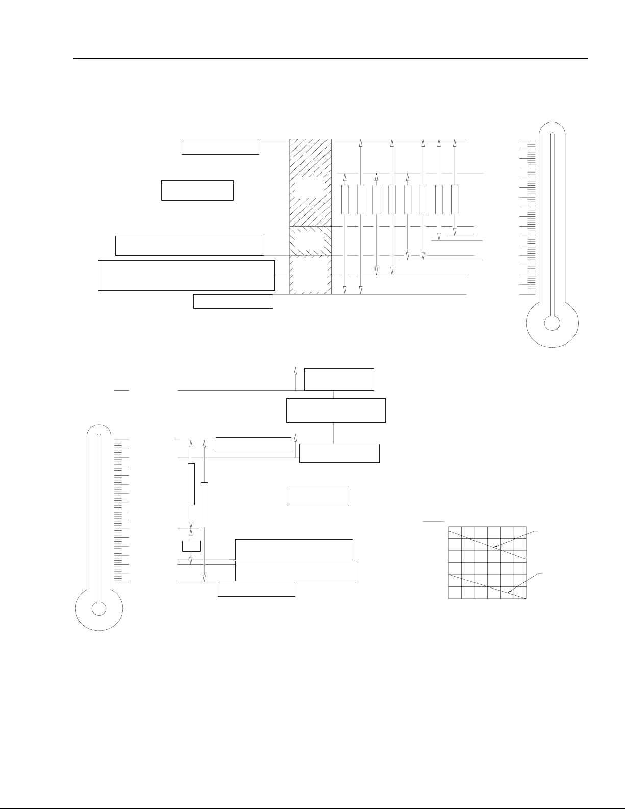
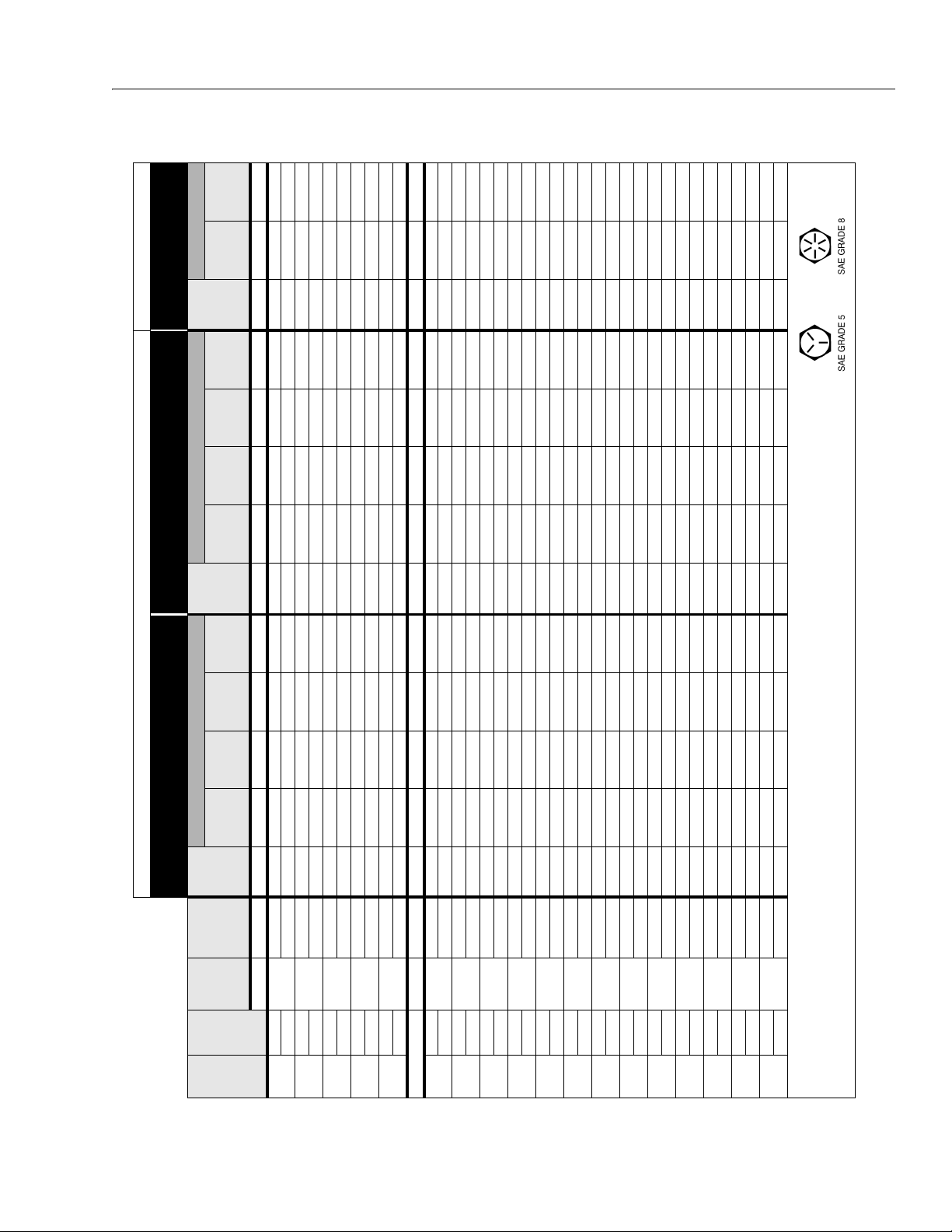
1-3. Torque Chart - (In/Lb - Ft/Lb). (For ASTM Fasteners) . . . . . . . . . . . . . . . . . . . . . . . . . . . . . . . . . .1-6
1-4. Torque Chart (Metric Conversion) - (For ASTM Fasteners) . . . . . . . . . . . . . . . . . . . . . . . . . . . . . .1-7
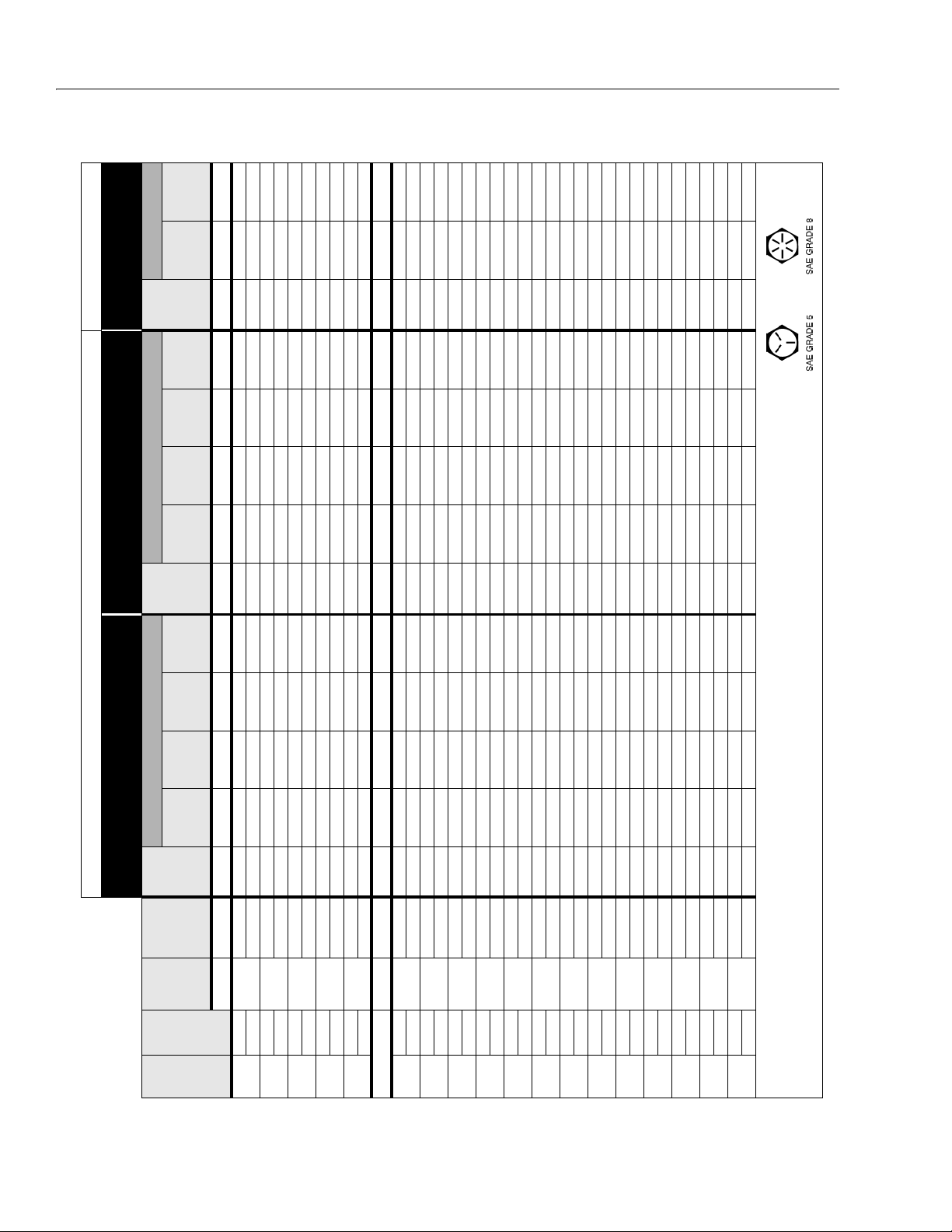
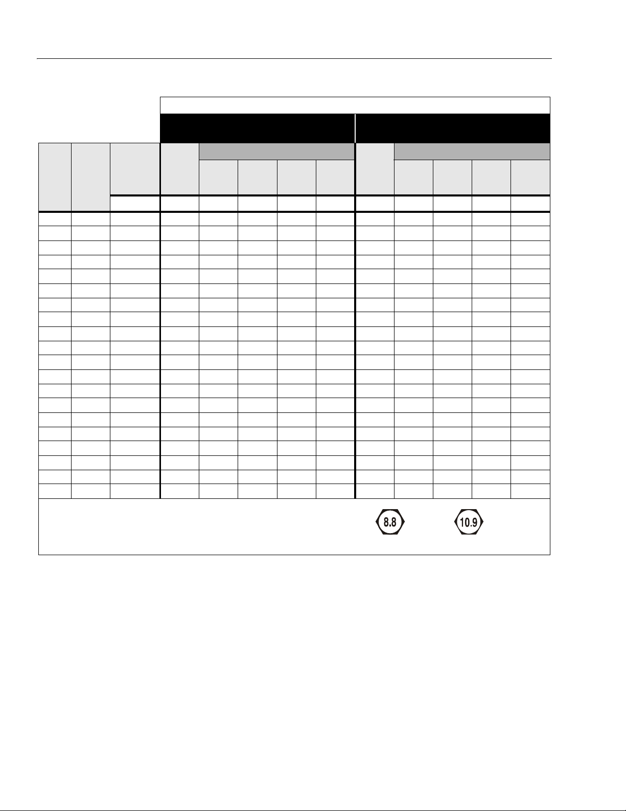
1-5. Torque Chart - (Nm) - (For Metric Class Fasteners). . . . . . . . . . . . . . . . . . . . . . . . . . . . . . . . . . . .1-8
2-1. Lubrication Diagram . . . . . . . . . . . . . . . . . . . . . . . . . . . . . . . . . . . . . . . . . . . . . . . . . . . . . . . . . . . .2-5
3-1. Drive Hub. . . . . . . . . . . . . . . . . . . . . . . . . . . . . . . . . . . . . . . . . . . . . . . . . . . . . . . . . . . . . . . . . . . . .3-2
3-2. Wheel Assembly Removal. . . . . . . . . . . . . . . . . . . . . . . . . . . . . . . . . . . . . . . . . . . . . . . . . . . . . . . . 3-4
3-3. Hub Torque Values . . . . . . . . . . . . . . . . . . . . . . . . . . . . . . . . . . . . . . . . . . . . . . . . . . . . . . . . . . . . .3-5
3-4. Drive Hub Assembly . . . . . . . . . . . . . . . . . . . . . . . . . . . . . . . . . . . . . . . . . . . . . . . . . . . . . . . . . . . .3-6
3-5. Drive Motor (OMR 100) . . . . . . . . . . . . . . . . . . . . . . . . . . . . . . . . . . . . . . . . . . . . . . . . . . . . . . . . . .3-7
3-6. Steering Assembly . . . . . . . . . . . . . . . . . . . . . . . . . . . . . . . . . . . . . . . . . . . . . . . . . . . . . . . . . . . . .3-9
3-7. Rear Axle Removal . . . . . . . . . . . . . . . . . . . . . . . . . . . . . . . . . . . . . . . . . . . . . . . . . . . . . . . . . . . . .3-10
3-8. Outrigger Cylinder Removal - (Sheet 1 of 2). . . . . . . . . . . . . . . . . . . . . . . . . . . . . . . . . . . . . . . . . .3-11
3-9. Outrigger Cylinder Removal - (Sheet 2 of 2). . . . . . . . . . . . . . . . . . . . . . . . . . . . . . . . . . . . . . . . . .3-12
3-10. Hood Assembly. . . . . . . . . . . . . . . . . . . . . . . . . . . . . . . . . . . . . . . . . . . . . . . . . . . . . . . . . . . . . . . .3-13
3-11. Deutz Engine . . . . . . . . . . . . . . . . . . . . . . . . . . . . . . . . . . . . . . . . . . . . . . . . . . . . . . . . . . . . . . . . . . 3-14
3-12. Engine Tray Slide . . . . . . . . . . . . . . . . . . . . . . . . . . . . . . . . . . . . . . . . . . . . . . . . . . . . . . . . . . . . . .3-15
3-13. Glow Plugs . . . . . . . . . . . . . . . . . . . . . . . . . . . . . . . . . . . . . . . . . . . . . . . . . . . . . . . . . . . . . . . . . . .3-16
3-14. Engine Solenoid . . . . . . . . . . . . . . . . . . . . . . . . . . . . . . . . . . . . . . . . . . . . . . . . . . . . . . . . . . . . . . . 3-16
3-15. Gear Pump Assembly . . . . . . . . . . . . . . . . . . . . . . . . . . . . . . . . . . . . . . . . . . . . . . . . . . . . . . . . . . .3-17
3-16. Gear Pump . . . . . . . . . . . . . . . . . . . . . . . . . . . . . . . . . . . . . . . . . . . . . . . . . . . . . . . . . . . . . . . . . . . 3-18
3-17. Exhaust Pipe Assembly. . . . . . . . . . . . . . . . . . . . . . . . . . . . . . . . . . . . . . . . . . . . . . . . . . . . . . . . . . 3-19
3-18. Air Filter Assembly. . . . . . . . . . . . . . . . . . . . . . . . . . . . . . . . . . . . . . . . . . . . . . . . . . . . . . . . . . . . . . 3-20
3-19. Engine Removal . . . . . . . . . . . . . . . . . . . . . . . . . . . . . . . . . . . . . . . . . . . . . . . . . . . . . . . . . . . . . . .3-21
3-20. Hydraulic Tank Removal . . . . . . . . . . . . . . . . . . . . . . . . . . . . . . . . . . . . . . . . . . . . . . . . . . . . . . . . .3-22
3-21. Pressure Filter Removal . . . . . . . . . . . . . . . . . . . . . . . . . . . . . . . . . . . . . . . . . . . . . . . . . . . . . . . . .3-23
3-22. Fuel Tank Removal . . . . . . . . . . . . . . . . . . . . . . . . . . . . . . . . . . . . . . . . . . . . . . . . . . . . . . . . . . . . . 3-24
3-23. Ground Control Panel Removal . . . . . . . . . . . . . . . . . . . . . . . . . . . . . . . . . . . . . . . . . . . . . . . . . . . 3-25
3-24. Battery Removal . . . . . . . . . . . . . . . . . . . . . . . . . . . . . . . . . . . . . . . . . . . . . . . . . . . . . . . . . . . . . . .3-26
3-25. Platform Control Box . . . . . . . . . . . . . . . . . . . . . . . . . . . . . . . . . . . . . . . . . . . . . . . . . . . . . . . . . . . . 3-27
3-26. Joystick . . . . . . . . . . . . . . . . . . . . . . . . . . . . . . . . . . . . . . . . . . . . . . . . . . . . . . . . . . . . . . . . . . . . . . 3-28
3-27. Platform Receptacle Box Removal . . . . . . . . . . . . . . . . . . . . . . . . . . . . . . . . . . . . . . . . . . . . . . . . . 3-29
3-28. Extension End Rail Removal . . . . . . . . . . . . . . . . . . . . . . . . . . . . . . . . . . . . . . . . . . . . . . . . . . . . . . 3-30
3-29. Extension Side Rail Removal . . . . . . . . . . . . . . . . . . . . . . . . . . . . . . . . . . . . . . . . . . . . . . . . . . . . .3-31
3-30. End Rail Removal . . . . . . . . . . . . . . . . . . . . . . . . . . . . . . . . . . . . . . . . . . . . . . . . . . . . . . . . . . . . . . 3-32
3-31. Side Rails Removal . . . . . . . . . . . . . . . . . . . . . . . . . . . . . . . . . . . . . . . . . . . . . . . . . . . . . . . . . . . . . 3-33
iv – JLG Lift – 3121322
Page 9

3-32. Platform Removal - 1 of 2 (Front of Platform) . . . . . . . . . . . . . . . . . . . . . . . . . . . . . . . . . . . . . . . . .3-34
3-33. Platform Removal - 2 of 2 (Rear of Platform) . . . . . . . . . . . . . . . . . . . . . . . . . . . . . . . . . . . . . . . . .3-35
3-34. Ladder Installation . . . . . . . . . . . . . . . . . . . . . . . . . . . . . . . . . . . . . . . . . . . . . . . . . . . . . . . . . . . . . . 3-36
3-35. Beacon Installation . . . . . . . . . . . . . . . . . . . . . . . . . . . . . . . . . . . . . . . . . . . . . . . . . . . . . . . . . . . . .3-37
3-36. Scissor Arm Limit Switch Adjustment . . . . . . . . . . . . . . . . . . . . . . . . . . . . . . . . . . . . . . . . . . . . . . .3-38
3-37. Lift Cylinder Removal . . . . . . . . . . . . . . . . . . . . . . . . . . . . . . . . . . . . . . . . . . . . . . . . . . . . . . . . . . .3-42
3-38. Scissor Arm Removal (Left Side) . . . . . . . . . . . . . . . . . . . . . . . . . . . . . . . . . . . . . . . . . . . . . . . . . .3-43
3-39. Scissor Arm Removal (Right Side) . . . . . . . . . . . . . . . . . . . . . . . . . . . . . . . . . . . . . . . . . . . . . . . . .3-43
4-1. Lift Cylinder Valve Block Removal. . . . . . . . . . . . . . . . . . . . . . . . . . . . . . . . . . . . . . . . . . . . . . . . . .4-2
4-2. Safety Valve and Limit Switch Removal . . . . . . . . . . . . . . . . . . . . . . . . . . . . . . . . . . . . . . . . . . . . .4-3
4-3. Cylinder Barrel Support. . . . . . . . . . . . . . . . . . . . . . . . . . . . . . . . . . . . . . . . . . . . . . . . . . . . . . . . . .4-3
4-4. Cylinder Head Removal . . . . . . . . . . . . . . . . . . . . . . . . . . . . . . . . . . . . . . . . . . . . . . . . . . . . . . . . .4-3
4-5. Cylinder Rod Support . . . . . . . . . . . . . . . . . . . . . . . . . . . . . . . . . . . . . . . . . . . . . . . . . . . . . . . . . . . 4-4
4-6. Piston Setscrew Removal . . . . . . . . . . . . . . . . . . . . . . . . . . . . . . . . . . . . . . . . . . . . . . . . . . . . . . . .4-4
4-7. Piston Removal . . . . . . . . . . . . . . . . . . . . . . . . . . . . . . . . . . . . . . . . . . . . . . . . . . . . . . . . . . . . . . . . 4-4
4-8. Piston Seals. . . . . . . . . . . . . . . . . . . . . . . . . . . . . . . . . . . . . . . . . . . . . . . . . . . . . . . . . . . . . . . . . . .4-4
4-9. Spacer Removal . . . . . . . . . . . . . . . . . . . . . . . . . . . . . . . . . . . . . . . . . . . . . . . . . . . . . . . . . . . . . . .4-5
4-10. Cylinder Head Removal . . . . . . . . . . . . . . . . . . . . . . . . . . . . . . . . . . . . . . . . . . . . . . . . . . . . . . . . .4-5
4-11. Cylinder Head Seals . . . . . . . . . . . . . . . . . . . . . . . . . . . . . . . . . . . . . . . . . . . . . . . . . . . . . . . . . . . .4-5
4-12. Bushing Installation . . . . . . . . . . . . . . . . . . . . . . . . . . . . . . . . . . . . . . . . . . . . . . . . . . . . . . . . . . . . . 4-6
4-13. Rod Seal Installation . . . . . . . . . . . . . . . . . . . . . . . . . . . . . . . . . . . . . . . . . . . . . . . . . . . . . . . . . . . . 4-6
4-14. Cylinder Head Seal Installation . . . . . . . . . . . . . . . . . . . . . . . . . . . . . . . . . . . . . . . . . . . . . . . . . . . .4-7
4-15. Cylinder Head Installation . . . . . . . . . . . . . . . . . . . . . . . . . . . . . . . . . . . . . . . . . . . . . . . . . . . . . . . . 4-7
4-16. Spacer Installation. . . . . . . . . . . . . . . . . . . . . . . . . . . . . . . . . . . . . . . . . . . . . . . . . . . . . . . . . . . . . .4-7
4-17. Piston Seal Installation . . . . . . . . . . . . . . . . . . . . . . . . . . . . . . . . . . . . . . . . . . . . . . . . . . . . . . . . . .4-7
4-18. Piston Installation . . . . . . . . . . . . . . . . . . . . . . . . . . . . . . . . . . . . . . . . . . . . . . . . . . . . . . . . . . . . . .4-8
4-19. Piston Setscrew Installation . . . . . . . . . . . . . . . . . . . . . . . . . . . . . . . . . . . . . . . . . . . . . . . . . . . . . .4-8
4-20. Rod Installation . . . . . . . . . . . . . . . . . . . . . . . . . . . . . . . . . . . . . . . . . . . . . . . . . . . . . . . . . . . . . . . .4-8
4-21. Rod Assembly Installation. . . . . . . . . . . . . . . . . . . . . . . . . . . . . . . . . . . . . . . . . . . . . . . . . . . . . . . .4-9
4-22. Valve Block Installation . . . . . . . . . . . . . . . . . . . . . . . . . . . . . . . . . . . . . . . . . . . . . . . . . . . . . . . . . .4-9
4-23. Safety Valve and Limit Switch Installation. . . . . . . . . . . . . . . . . . . . . . . . . . . . . . . . . . . . . . . . . . . . 4-9
4-24. Lifting Cylinder Assembly . . . . . . . . . . . . . . . . . . . . . . . . . . . . . . . . . . . . . . . . . . . . . . . . . . . . . . . .4-10
4-25. Steering Cylinder Assembly . . . . . . . . . . . . . . . . . . . . . . . . . . . . . . . . . . . . . . . . . . . . . . . . . . . . . .4-11
4-26. Leveling Cylinder Assembly . . . . . . . . . . . . . . . . . . . . . . . . . . . . . . . . . . . . . . . . . . . . . . . . . . . . . .4-12
4-27. Extension Cylinder Assembly . . . . . . . . . . . . . . . . . . . . . . . . . . . . . . . . . . . . . . . . . . . . . . . . . . . . .4-13
4-28. Arms and Platform Positioning and Support . . . . . . . . . . . . . . . . . . . . . . . . . . . . . . . . . . . . . . . . .4-14
4-29. Valve/Hydraulic Compartment . . . . . . . . . . . . . . . . . . . . . . . . . . . . . . . . . . . . . . . . . . . . . . . . . . . . 4-15
4-30. Pressure Switch Adjustment . . . . . . . . . . . . . . . . . . . . . . . . . . . . . . . . . . . . . . . . . . . . . . . . . . . . . .4-15
4-31. Brake Valve . . . . . . . . . . . . . . . . . . . . . . . . . . . . . . . . . . . . . . . . . . . . . . . . . . . . . . . . . . . . . . . . . . . 4-16
4-32. Brake Valve Adjustment . . . . . . . . . . . . . . . . . . . . . . . . . . . . . . . . . . . . . . . . . . . . . . . . . . . . . . . . .4-16
4-33. Main Valve Block . . . . . . . . . . . . . . . . . . . . . . . . . . . . . . . . . . . . . . . . . . . . . . . . . . . . . . . . . . . . . . .4-17
4-34. Pressure Test Port . . . . . . . . . . . . . . . . . . . . . . . . . . . . . . . . . . . . . . . . . . . . . . . . . . . . . . . . . . . . . .4-18
4-35. Main Valve Pressure Adjustment . . . . . . . . . . . . . . . . . . . . . . . . . . . . . . . . . . . . . . . . . . . . . . . . . .4-18
4-36. Steering Valve . . . . . . . . . . . . . . . . . . . . . . . . . . . . . . . . . . . . . . . . . . . . . . . . . . . . . . . . . . . . . . . . .4-18
4-37. Steer Valve Pressure Adjustment . . . . . . . . . . . . . . . . . . . . . . . . . . . . . . . . . . . . . . . . . . . . . . . . . .4-19
4-38. Drive Valve. . . . . . . . . . . . . . . . . . . . . . . . . . . . . . . . . . . . . . . . . . . . . . . . . . . . . . . . . . . . . . . . . . . .4-20
4-39. Hand Pump Assembly. . . . . . . . . . . . . . . . . . . . . . . . . . . . . . . . . . . . . . . . . . . . . . . . . . . . . . . . . . .4-21
4-40. Hand Pump Schematic . . . . . . . . . . . . . . . . . . . . . . . . . . . . . . . . . . . . . . . . . . . . . . . . . . . . . . . . . .4-22
4-41. Lift/Lower Valve Block . . . . . . . . . . . . . . . . . . . . . . . . . . . . . . . . . . . . . . . . . . . . . . . . . . . . . . . . . . .4-22
4-42. Platform Lower Flow Valve . . . . . . . . . . . . . . . . . . . . . . . . . . . . . . . . . . . . . . . . . . . . . . . . . . . . . . .4-23
4-43. Outrigger Valves . . . . . . . . . . . . . . . . . . . . . . . . . . . . . . . . . . . . . . . . . . . . . . . . . . . . .
5-1. Main Terminal Box. . . . . . . . . . . . . . . . . . . . . . . . . . . . . . . . . . . . . . . . . . . . . . . . . . . . . . . . . . . . . .5-1
5-2. Control Card Complex 2 Board. . . . . . . . . . . . . . . . . . . . . . . . . . . . . . . . . . . . . . . . . . . . . . . . . . . . 5-2
5-3. Nivolux Control Board . . . . . . . . . . . . . . . . . . . . . . . . . . . . . . . . . . . . . . . . . . . . . . . . . . . . . . . . . . .5-5
6-1. Voltage Measurement (DC). . . . . . . . . . . . . . . . . . . . . . . . . . . . . . . . . . . . . . . . . . . . . . . . . . . . . . .6-2
6-2. Resistance Measurement . . . . . . . . . . . . . . . . . . . . . . . . . . . . . . . . . . . . . . . . . . . . . . . . . . . . . . . .6-2
6-3. Continuity Measurement . . . . . . . . . . . . . . . . . . . . . . . . . . . . . . . . . . . . . . . . . . . . . . . . . . . . . . . . .6-3
6-4. Current Measurement (DC). . . . . . . . . . . . . . . . . . . . . . . . . . . . . . . . . . . . . . . . . . . . . . . . . . . . . . .6-3
TABLE OF CONTENTS
. . . . . . . . . .4-23
3121322 – JLG Lift – v
Page 10

TABLE OF CONTENTS
6-5. AMP Connector . . . . . . . . . . . . . . . . . . . . . . . . . . . . . . . . . . . . . . . . . . . . . . . . . . . . . . . . . . . . . . . .6-5
6-6. Connector Assembly (1 of 4) . . . . . . . . . . . . . . . . . . . . . . . . . . . . . . . . . . . . . . . . . . . . . . . . . . . . .6-6
6-7. Connector Assembly (2 of 4) . . . . . . . . . . . . . . . . . . . . . . . . . . . . . . . . . . . . . . . . . . . . . . . . . . . . .6-6
6-8. Connector Assembly (3 of 4) . . . . . . . . . . . . . . . . . . . . . . . . . . . . . . . . . . . . . . . . . . . . . . . . . . . . .6-7
6-9. Connector Assembly (4 of 4) . . . . . . . . . . . . . . . . . . . . . . . . . . . . . . . . . . . . . . . . . . . . . . . . . . . . .6-7
6-10. Connector Disassembly . . . . . . . . . . . . . . . . . . . . . . . . . . . . . . . . . . . . . . . . . . . . . . . . . . . . . . . . . 6-8
6-11. Connector Installation . . . . . . . . . . . . . . . . . . . . . . . . . . . . . . . . . . . . . . . . . . . . . . . . . . . . . . . . . . .6-9
6-12. DT/DTP Contact Installation . . . . . . . . . . . . . . . . . . . . . . . . . . . . . . . . . . . . . . . . . . . . . . . . . . . . . .6-10
6-13. DT/DTP Contact Removal . . . . . . . . . . . . . . . . . . . . . . . . . . . . . . . . . . . . . . . . . . . . . . . . . . . . . . . .6-10
6-14. HD/HDP Contact Installation. . . . . . . . . . . . . . . . . . . . . . . . . . . . . . . . . . . . . . . . . . . . . . . . . . . . . .6-10
6-15. HD/HDP Locking Contacts Into Position . . . . . . . . . . . . . . . . . . . . . . . . . . . . . . . . . . . . . . . . . . . .6-11
6-16. HD/HDP Contact Removal . . . . . . . . . . . . . . . . . . . . . . . . . . . . . . . . . . . . . . . . . . . . . . . . . . . . . . . 6-11
6-17. HD/HDP Unlocking Contacts . . . . . . . . . . . . . . . . . . . . . . . . . . . . . . . . . . . . . . . . . . . . . . . . . . . . . 6-11
6-18. Electrical Schematic - Sheet 1 of 15 . . . . . . . . . . . . . . . . . . . . . . . . . . . . . . . . . . . . . . . . . . . . . . . .6-12
6-19. Electrical Schematic - Sheet 2 of 15 . . . . . . . . . . . . . . . . . . . . . . . . . . . . . . . . . . . . . . . . . . . . . . . .6-13
6-20. Electrical Components - Sheet 3 of 15 . . . . . . . . . . . . . . . . . . . . . . . . . . . . . . . . . . . . . . . . . . . . . .6-14
6-21. Electrical Schematic - Sheet 4 of 15 . . . . . . . . . . . . . . . . . . . . . . . . . . . . . . . . . . . . . . . . . . . . . . . .6-15
6-22. Electrical Schematic - Sheet 5 of 15 . . . . . . . . . . . . . . . . . . . . . . . . . . . . . . . . . . . . . . . . . . . . . . . .6-16
6-23. Electrical Schematic - Sheet 6 of 15 . . . . . . . . . . . . . . . . . . . . . . . . . . . . . . . . . . . . . . . . . . . . . . . .6-17
6-24. Electrical Schematic - Sheet 7 of 15 . . . . . . . . . . . . . . . . . . . . . . . . . . . . . . . . . . . . . . . . . . . . . . . .6-18
6-25. Electrical Schematic - Sheet 8 of 15 . . . . . . . . . . . . . . . . . . . . . . . . . . . . . . . . . . . . . . . . . . . . . . . .6-19
6-26. Electrical Schematic - Sheet 9 of 15 . . . . . . . . . . . . . . . . . . . . . . . . . . . . . . . . . . . . . . . . . . . . . . . .6-20
6-27. Electrical Schematic - Sheet 10 of 15 . . . . . . . . . . . . . . . . . . . . . . . . . . . . . . . . . . . . . . . . . . . . . . .6-21
6-28. Electrical Schematic - Sheet 11 of 15 . . . . . . . . . . . . . . . . . . . . . . . . . . . . . . . . . . . . . . . . . . . . . . .6-22
6-29. Electrical Schematic - Sheet 12 of 15 . . . . . . . . . . . . . . . . . . . . . . . . . . . . . . . . . . . . . . . . . . . . . . .6-23
6-30. Electrical Schematic - Sheet 13 of 15 . . . . . . . . . . . . . . . . . . . . . . . . . . . . . . . . . . . . . . . . . . . . . . .6-24
6-31. Electrical Schematic - Sheet 14 of 15 . . . . . . . . . . . . . . . . . . . . . . . . . . . . . . . . . . . . . . . . . . . . . . .6-25
6-32. Electrical Schematic - Sheet 15 of 15 . . . . . . . . . . . . . . . . . . . . . . . . . . . . . . . . . . . . . . . . . . . . . . .6-26
6-33. Electrical Diagram - Sheet 1 of 2. . . . . . . . . . . . . . . . . . . . . . . . . . . . . . . . . . . . . . . . . . . . . . . . . . .6-34
6-34. Electrical Diagram - Sheet 2 of 2. . . . . . . . . . . . . . . . . . . . . . . . . . . . . . . . . . . . . . . . . . . . . . . . . . .6-35
6-35. Hydraulic Diagram - H900049 RevF - Sheet 1 of 2. . . . . . . . . . . . . . . . . . . . . . . . . . . . . . . . . . . . .6-36
6-36. Hydraulic Diagram - H900049 RevF - Sheet 2 of 2. . . . . . . . . . . . . . . . . . . . . . . . . . . . . . . . . . . . .6-37
6-37. Hydraulic Schematic - 1001091308 RevB . . . . . . . . . . . . . . . . . . . . . . . . . . . . . . . . . . . . . . . . . . .6-38
vi – JLG Lift – 3121322
Page 11

TABLE OF CONTENTS
LIST OF TABLES
TABLE NO. TITLE PAGE NO.
1-1 Operating Specifications. . . . . . . . . . . . . . . . . . . . . . . . . . . . . . . . . . . . . . . . . . . . . . . . . . . . . . . . .1-1
1-2 Dimensional Data . . . . . . . . . . . . . . . . . . . . . . . . . . . . . . . . . . . . . . . . . . . . . . . . . . . . . . . . . . . . . . 1-1
1-3 Capacities . . . . . . . . . . . . . . . . . . . . . . . . . . . . . . . . . . . . . . . . . . . . . . . . . . . . . . . . . . . . . . . . . . . .1-1
1-4 Engine Specifications . . . . . . . . . . . . . . . . . . . . . . . . . . . . . . . . . . . . . . . . . . . . . . . . . . . . . . . . . . . 1-2
1-5 Engine Battery Specifications . . . . . . . . . . . . . . . . . . . . . . . . . . . . . . . . . . . . . . . . . . . . . . . . . . . . .1-2
1-6 Tire Specifications . . . . . . . . . . . . . . . . . . . . . . . . . . . . . . . . . . . . . . . . . . . . . . . . . . . . . . . . . . . . . . 1-2
1-7 Pressure Setting . . . . . . . . . . . . . . . . . . . . . . . . . . . . . . . . . . . . . . . . . . . . . . . . . . . . . . . . . . . . . . .1-4
1-8 Major Component Weights . . . . . . . . . . . . . . . . . . . . . . . . . . . . . . . . . . . . . . . . . . . . . . . . . . . . . . .1-4
1-9 Critical Stability Weights . . . . . . . . . . . . . . . . . . . . . . . . . . . . . . . . . . . . . . . . . . . . . . . . . . . . . . . . . 1-4
1-10 Hydraulic Oil . . . . . . . . . . . . . . . . . . . . . . . . . . . . . . . . . . . . . . . . . . . . . . . . . . . . . . . . . . . . . . . . . .1-4
1-11 Mobil Hydraulic Fluid Specs . . . . . . . . . . . . . . . . . . . . . . . . . . . . . . . . . . . . . . . . . . . . . . . . . . . . . .1-4
2-1 Inspection and Maintenance. . . . . . . . . . . . . . . . . . . . . . . . . . . . . . . . . . . . . . . . . . . . . . . . . . . . . .2-2
2-2 Lubrication Specifications . . . . . . . . . . . . . . . . . . . . . . . . . . . . . . . . . . . . . . . . . . . . . . . . . . . . . . . .2-4
2-3 Preventive Maintenance and Safety Inspection . . . . . . . . . . . . . . . . . . . . . . . . . . . . . . . . . . . . . . . 2-11
3-1 Drive Hub Technical Specifications . . . . . . . . . . . . . . . . . . . . . . . . . . . . . . . . . . . . . . . . . . . . . . . .3-3
3-2 Drive Motor Specs. . . . . . . . . . . . . . . . . . . . . . . . . . . . . . . . . . . . . . . . . . . . . . . . . . . . . . . . . . . . . .3-7
3-3 Tightening Torques . . . . . . . . . . . . . . . . . . . . . . . . . . . . . . . . . . . . . . . . . . . . . . . . . . . . . . . . . . . . .3-8
3-4 Engine Technical Data . . . . . . . . . . . . . . . . . . . . . . . . . . . . . . . . . . . . . . . . . . . . . . . . . . . . . . . . . .3-14
3-5 Gear Pump Specs. . . . . . . . . . . . . . . . . . . . . . . . . . . . . . . . . . . . . . . . . . . . . . . . . . . . . . . . . . . . . .3-18
3-6 Joystick Specifications . . . . . . . . . . . . . . . . . . . . . . . . . . . . . . . . . . . . . . . . . . . . . . . . . . . . . . . . . .3-28
3-7 Plug Loading Chart . . . . . . . . . . . . . . . . . . . . . . . . . . . . . . . . . . . . . . . . . . . . . . . . . . . . . . . . . . . . .3-28
3-8 Beacon Harness MTB Connections . . . . . . . . . . . . . . . . . . . . . . . . . . . . . . . . . . . . . . . . . . . . . . . .3-37
4-1 Steering Cylinder Specs . . . . . . . . . . . . . . . . . . . . . . . . . . . . . . . . . . . . . . . . . . . . . . . . . . . . . . . . .4-11
4-2 Leveling Cylinder Specs . . . . . . . . . . . . . . . . . . . . . . . . . . . . . . . . . . . . . . . . . . . . . . . . . . . . . . . . .4-12
4-3 Extension Cylinder Specs . . . . . . . . . . . . . . . . . . . . . . . . . . . . . . . . . . . . . . . . . . . . . . . . . . . . . . . . 4-13
5-1 J1 Connector. . . . . . . . . . . . . . . . . . . . . . . . . . . . . . . . . . . . . . . . . . . . . . . . . . . . . . . . . . . . . . . . . .5-3
5-2 J2 Connector. . . . . . . . . . . . . . . . . . . . . . . . . . . . . . . . . . . . . . . . . . . . . . . . . . . . . . . . . . . . . . . . . .5-3
5-3 J3 Connector. . . . . . . . . . . . . . . . . . . . . . . . . . . . . . . . . . . . . . . . . . . . . . . . . . . . . . . . . . . . . . . . . .5-3
5-4 Complex 2 Circuit Board. . . . . . . . . . . . . . . . . . . . . . . . . . . . . . . . . . . . . . . . . . . . . . . . . . . . . . . . .5-4
5-5 NIVOLUX Circuit Board . . . . . . . . . . . . . . . . . . . . . . . . . . . . . . . . . . . . . . . . . . . . . . . . . . . . . . . . . .5-7
5-6 PNP Circuit Board - I/O . . . . . . . . . . . . . . . . . . . . . . . . . . . . . . . . . . . . . . . . . . . . . . . . . . . . . . . . . .5-8
5-7 Connector J1. . . . . . . . . . . . . . . . . . . . . . . . . . . . . . . . . . . . . . . . . . . . . . . . . . . . . . . . . . . . . . . . . .5-8
5-8 Connector J2. . . . . . . . . . . . . . . . . . . . . . . . . . . . . . . . . . . . . . . . . . . . . . . . . . . . . . . . . . . . . . . . . .5-8
5-9 Connector CON1. . . . . . . . . . . . . . . . . . . . . . . . . . . . . . . . . . . . . . . . . . . . . . . . . . . . . . . . . . . . . . .5-9
5-10 Trigger Control Circuit Board . . . . . . . . . . . . . . . . . . . . . . . . . . . . . . . . . . . . . . . . . . . . . . . . . . . . .5-9
5-11 Limit Switches . . . . . . . . . . . . . . . . . . . . . . . . . . . . . . . . . . . . . . . . . . . . . . . . . . . . . . . . . . . . . . . . .5-10
5-12 Deutz Engine Control Board . . . . . . . . . . . . . . . . . . . . . . . . . . . . . . . . . . . . . . . . . . . . . . . . . . . . . .5-12
5-13 Deutz Engine . . . . . . . . . . . . . . . . . . . . . . . . . . . . . . . . . . . . . . . . . . . . . . . . . . . . . . . . . . . . . . . . . .5-12
6-1 Main Terminal Box Wiring Description . . . . . . . . . . . . . . . . . . . . . . . . . . . . . . . . . . . . . . . . . . . . . . 6-27
3121322 – JLG Lift – vii
Page 12

TABLE OF CONTENTS
This page left blank intentionally.
viii – JLG Lift – 3121322
Page 13
SECTION 1 - SPECIFICATIONS
SECTION 1. SPECIFICATIONS
1.1 OPERATING SPECIFICATIONS 1.2 DIMENSIONAL DATA
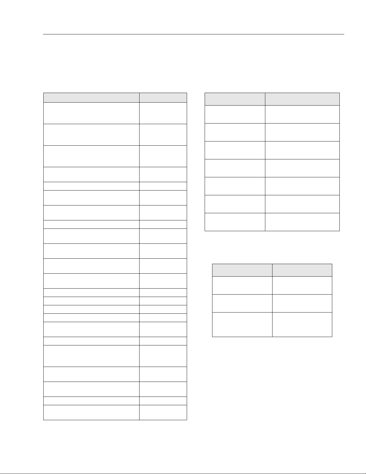
Table 1-1. Operating Specifications
Description 67SL
Maximum Working Height:
wit h ou tr i gg e rs de p lo yed
wit h ou tr i gg e rs st o we d
Maximum Platform Height:
wit h ou tr i gg e rs de p lo yed
wit h ou tr i gg e rs st o we d
Tu rn in g R ad iu s:
I ns i d e
O ut s i de
Maximum Work Load (Capacity) Main Platform/Platform Extension
Maximum Occupants 4
Tools and Equipment Main Platform / Platform Extension
Maximum Horizontal Manual Side Force
Tilt Sensor Setting 3°
Maximum Operating Wind Speed
Gross Machine Weight (Approximate)
Drive Speed (slow)
Drive Speed (fast)
Sideslope (Machine Stowed) 5°
Gradeability (MachineStowed) 25%
Lift Speed (no load) 95 sec
Lowering Speed 60 sec
Maximum Operating Hydraulic Pressure
Power Supply Diesel Engine
Maximum Ground Bearing Pressure:
Outriggers
T ir e s
Maximum Tire Load
Maximum Outrigger Pad Load
Electrical System Voltage 24 V
Ground Clearance
73.2 ft (22.3 m)
56.8 ft (17.3 m)
66.7 ft (20.3 m)
50 ft (15.2 m)
3.9 ft (1.2 m)
17.1 ft (5.2 m )
1650 lbs/1100 lbs
(750 kg/500 kg)
1300 lbs/397 lbs
(430 kg/180 kg)
200 Lb force
(890N)
28 mph
(12.5 m/s)
25,133 lbs
(11,400 kg)
0.4 mph (0.6 ft/sec)
(0.7 kmh)
2.2 mph (3.2 ft/sec)
(3.6 kmh)
3046 psi
(210 bar)
128 psi (9 kg/cm²)
71 psi (5 kg/cm²)
9700 lbs
(4400 kg)
9458 lbs
(4290 kg)
0.9 ft
(0.27 m)
Table 1-2. Dimensional Data
Description 67SL
Machine Height
(rails up)
Machine Height
(rails down)
Machine Width
Machine Length
Platform Dimensions
(extension retracted)
Platform Dimensions
(extension extended)
Transport Dimensions
(L x W x H)
1.3 CAPACITIES
Table 1-3. Capacities
Description 67SL
Fuel Tan k
Hydraulic Tank
Engine Crankcase
w it h F il t er
without Filter
3.8 m
(12.5 ft)
3 m
(9.9 ft)
2.4 m
(7.9 ft)
4.8 m
(15.7 ft)
4.6 x 2.4 m
(15 x 7.9 ft)
7.4 x 2.4 m
(24.3 x 7.9 f t)
4.8 x 2.4 x 3 m
(15.7 x 7.9 x 9.9 ft)
90 L
(23.8 gal)
135 L
(35.7 gal)
10.5 ltr (11 qt)
10 ltr (10.6 qt)
3121322 – JLG Lift – 1-1
Page 14
SECTION 1 - SPECIFICATIONS
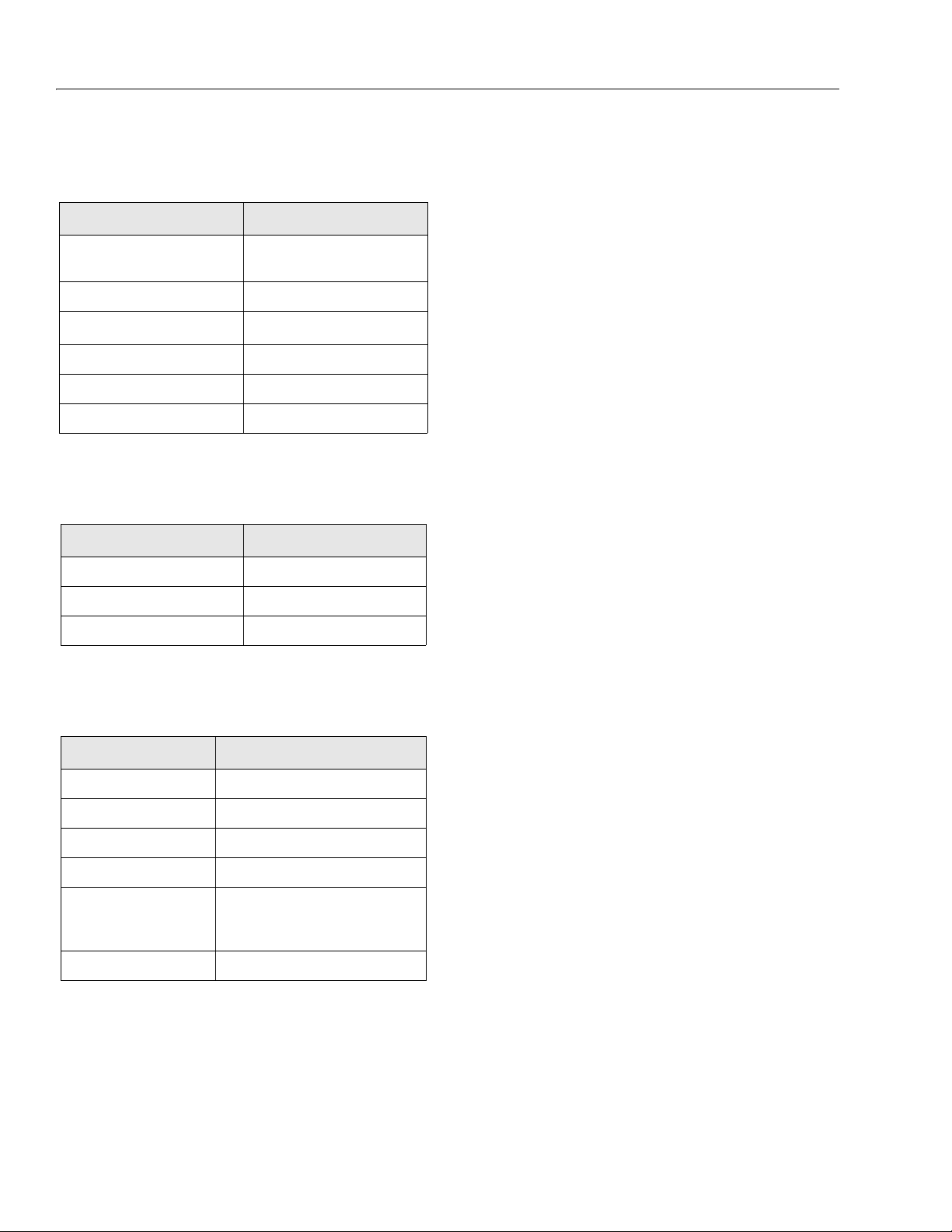
1.4 ENGINE
Table 1-4. Engine Specifications
Description 67SL
Ty pe
Number of Cylinders 3
Displacement
Bore 3.7 in (94 mm)
Stroke 4.4 in (112 mm)
Fuel Type Diesel
Deutz F3L 2011; or
Deutz D2011 L03i
3
140.4 in
Battery
Table 1-5. Engine Battery Specifications
Description 67SL
Voltage 12
Cranking Performance 100
Reser ve Capacity 880
(2.3L)
ure 1-5., Torque Chart - (Nm) - (For Metric Class
Fasteners).to determine proper torque value.
1.7 LIMIT SWITCHES
Platform Stowed/Jacks Retract Limit Switch
Outriggers cannot be deployed beyond the height of 9.8 ft
(3 m).
High Drive Speed Cutout Limit Switch
When the platform reaches and exceeds a height of 11.5 ft
(3.5 m), the fast drive speed will be cut back to the slow
drive speed. Once the platform is completely lowered, the
high drive speed is possible. The High Drive Cutout LED
on the platform control console will be out when the platform exceeds the limit.
Maximum Drive Height/Maximum Height without Outriggers Limit Switch
The drive function will be disabled once the platform
reaches a height of 50 ft (15.2 m). The platform must be
lowered below the limit to enable the drive function. The
lift function is also disabled once the platform reaches a
height of 50 ft (15.2 m) when the outriggers are not
deployed.
1.5 TIRES
Table 1-6. Tire Specifications
Description 67SL
Size IN355/55D625
Load Range G (14 Ply Rating)
Tire Pressure (foam fill) 90 psi (6.2 bar)
Max Tire Load 9700 lbs (4400 kg)
Wheel Lug Nut Torque:
Front Axle:
Rear Axle:
Bolt Size M18 x 1.5
354 ft lbs (480 Nm)
354 ft lbs (480 Nm)
1.6 TORQUE REQUIREMENTS
NOTE: JLG recommends that once any locknut is removed
from the machine it is discarded and replaced with a
new one. When maintenance becomes necessary or
a fastener has loosened, refer to Figure 1-3., Torque
Chart - (In/Lb - Ft/Lb). (For ASTM Fasteners) to Fig-
Maximum Height Limit Switch
Once the platform has reached its maximum height of
66.6 ft (20.3 m), the lifting function will be cut off by the
maximum height limit switch. This maximum height can
only be achieved when the outriggers are selected and
deployed. When maximum height is reached, the Lift Cutout Indicator LED on the platform control console will no
longer be iluminated.
Tilt Sensor
The tilt switch cuts out lifting, driving, and steering once
the platform reaches a tilt angle (slope) beyond 3° and the
platform height exceeds 11.5 ft (3.5 m). At this point, the
warning LED on the platform control console will be illuminate. Lowering is the only function possible.
Outrigger Interlock Sensors
Outriggers Selected - Limit switch senses ground contact
for all outriggers to enable platform to be raised.
Outriggers Not Selected - Limit switch senses when all
outriggers are retracted to enable platform to be raised
and machine to be driven.
1-2 – JLG Lift – 3121322
Page 15
SECTION 1 - SPECIFICATIONS
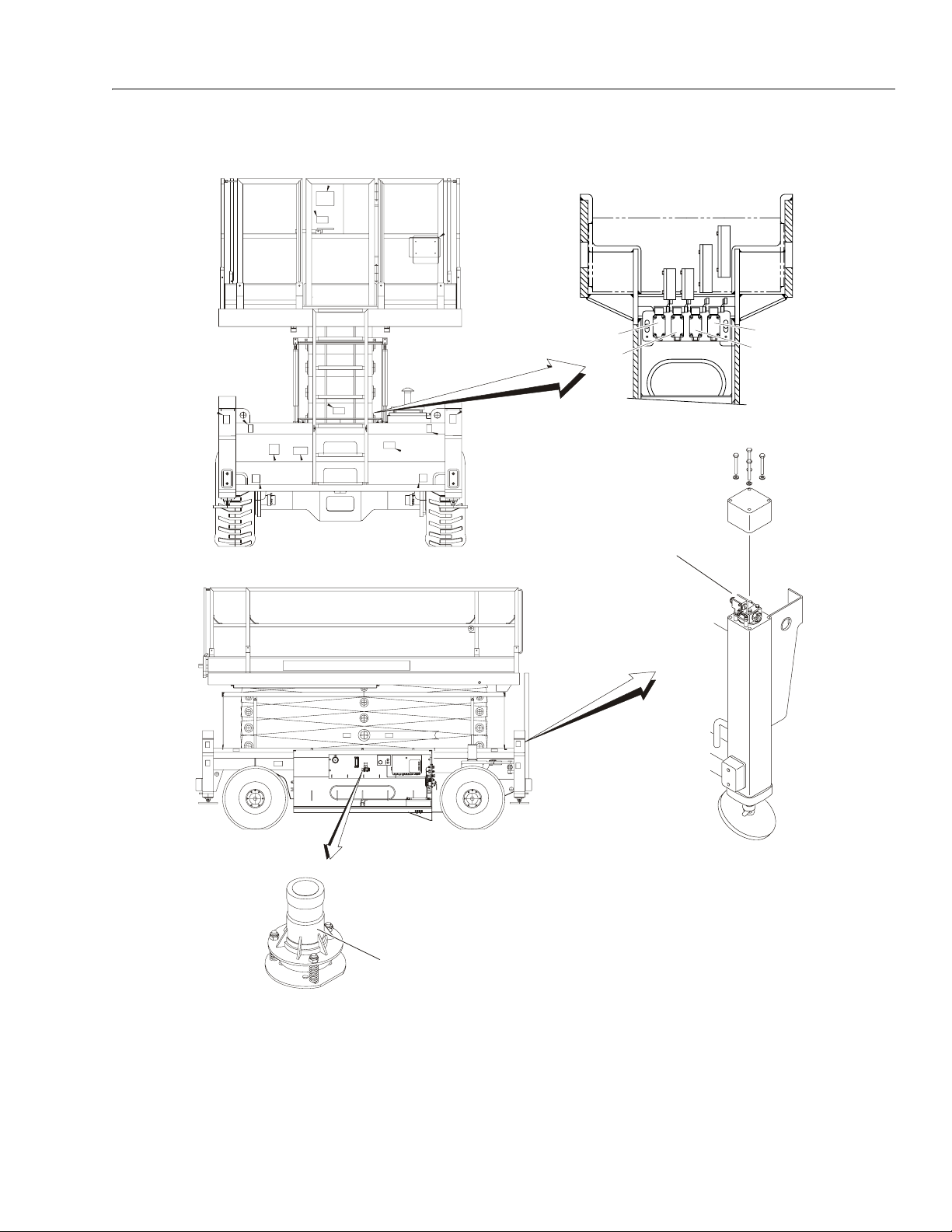
1
2
3
4
6
5
1. Platform Stowed/Jacks Retract Limit Switch 4. Maximum Height Limit Switch
2. High Drive Speed Cutout Limit Switch 5. Tilt Sensor
3. Maximum Drive Height/Maximum Height without Outriggers
Limit Switch
Figure 1-1. Limit Switch Locations
3121322 – JLG Lift – 1-3
6. Outrigger Sensor (all 4 outriggers)
Page 16
SECTION 1 - SPECIFICATIONS
1.8 PRESSURE SETTING
Cold temperatures have a significant impact on pressure
readings. JLG Industries Inc. recommends setting the
pressures with the operating temperature between 59°68°F (15°- 20°C). JLG Industries Inc. also recommends the
use of a calibrated gauge. The pressures may be set with
a tolerence of ± 43.5 psi (3 bar).
Table 1-7. Pressure Setting
Main Relief Steer Relief Pressure Switch
3046 psi
(210 bar)
2538 psi
(175 bar)
2683 psi
(185 bar)
1.9 MAJOR COMPONENT WEIGHTS
Table 1-8. Major Component Weights
Description Weight
Platform Assembly (including extension)
Platform Extension
Chassis
Arm Assembly
1962 lbs
(890 kg)
860 lbs
(390 kg)
8377 lbs
(3800 kg)
11,243 lbs
(5100 kg)
1.11 LUBRICATION
Hydraulic Oil
Table 1-10. Hydraulic Oil
HYDRAULIC SYSTEM OPERATING
TEMPERATURE RANGE
0° to +23° F
(-18° to -5° C)
0° to +210° F
(-18° to +100° C)
+50° to +210° F
(+10° to +100° C)
NOTE: Hydraulic oils must have anti-wear qualities at least
to API Service Classification GL-3, and sufficient
chemical stability for mobile hydraulic system service. JLG Industries recommends Mobilfluid 424
hydraulic oil, which has an SAE viscosity index of
152.
Aside from JLG recommendations, it is not advisable
to mix oils of different brands or types, as they may
not contain the same required additives or be of
comparable viscosities. If use of hydraulic oil other
than Mobilfluid 424 is desired, contact JLG Industries for proper recommendations.
When temperatures remain below 20°F (-7°C), JLG
Industries recommends the use of Mobil DTE 13M.
SAE VISCOSITY GRADE
10W
10W-20, 10W-30
20W-20
Lift Cylinder
1.10 CRITICAL STABILITY WEIGHTS
DO NOT REPLACE ITEMS CRITICAL TO STABILITY, SUCH AS BATTERIES OR SOLID TIRES, WITH ITEMS OF DIFFERENT WEIGHT
OR SPECIFICATION. DO NOT MODIFY UNIT IN ANY WAY TO
AFFECT STABILITY.
Table 1-9. Critical Stability Weights
Description Weight
Engine 478 lbs (217 kg)
Wheel and Tire Assembly (each) 441 lbs (200 kg)
Wheel/Tire and Drive Assembly (each) 542 lbs (246 kg)
Batteries - Standard (each) 54 lbs (24.6 kg)
992 lbs
(450 kg)
Table 1-11. Mobil Hydraulic Fluid Specs
Description Mobil 424 Mobil DTE 13M
ISO Viscosity Grade
Specific Gravity
Pour Poin t, Max
Flash Point, Min.
at 40° C (104°F)
at 100°C (212°F)
Viscosity Index
10W-30 #32
29.0 0.877
-43°F (-46°C) -40°F (-40°C)
442°F (228°C) 330°F (166°C)
Viscosity
55 cSt
9.3 cSt
152
33 cSt
6.5 cSt
140
1-4 – JLG Lift – 3121322
Page 17
SECTION 1 - SPECIFICATIONS
C
E
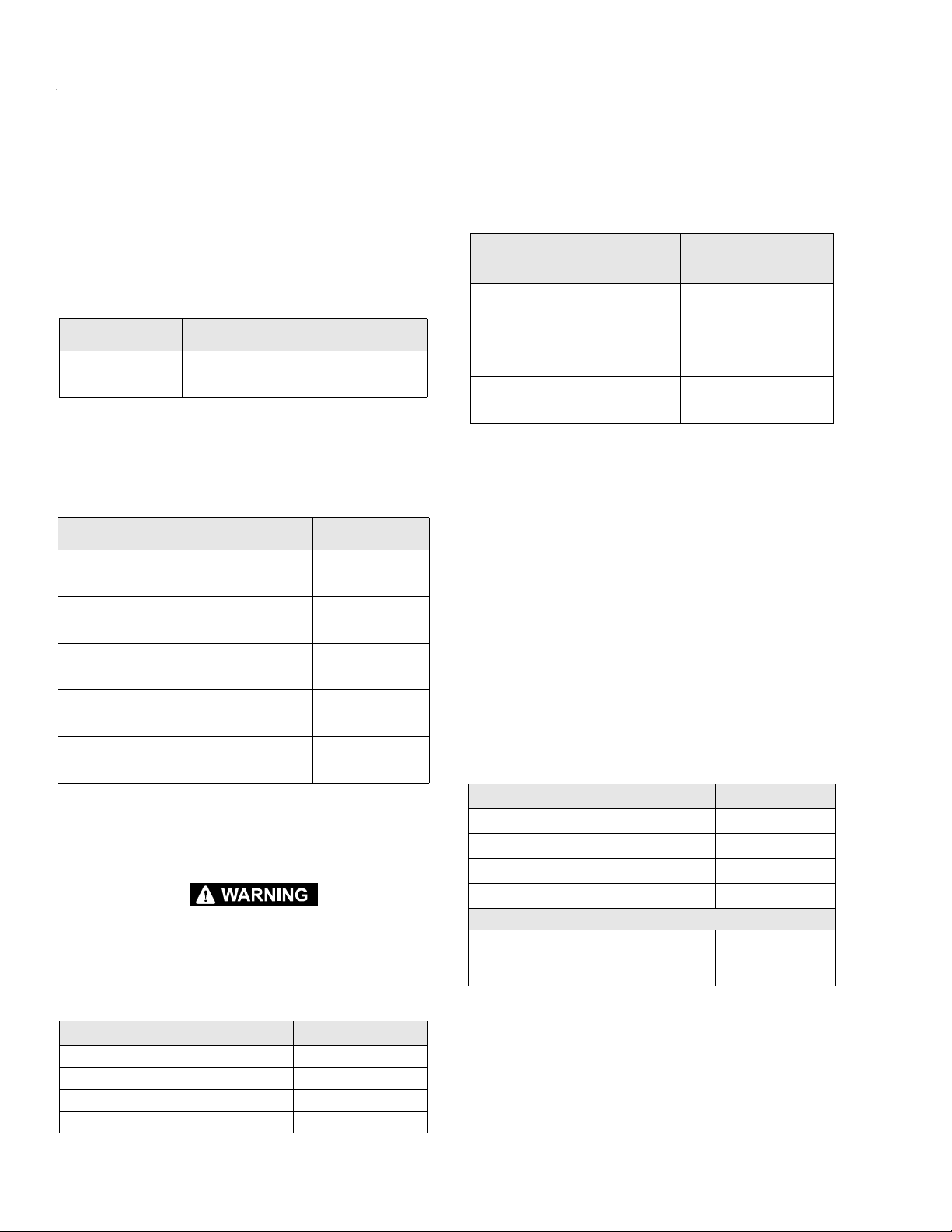
4150548
NO OPERATION ABOVE THIS
AMBIENT TEMPERATURE
ENGINE
SPECIFICATIONS
ENGINE WILL START AND OPERATE UNAIDED AT THIS
TEMPERATURE WITH THE RECOMMENDED FLUIDS AND A
FULLY CHARGED BATTERY
ENGINE WILL START AND OPERATE AT THIS TEMPERATURE
WITH THE RECOMMENDED FLUIDS, A FULLY CHARGED BATTERY
AND THE AID OF A COMPLETE JLG SPECIFIED COLD WEATHER
PACKAGE (IE. ENGINE BLOCK HEATER, ETHER INJECTION OR GLOW
PLUGS, BATTERY WARMER AND HYDRAULIC OIL TANK HEATER)
NO OPERATION BELOW THIS
AMBIENT TEMPERATURE
180°F (82°C)
(HYD. OIL TANK TEMP.
AMBIENT AIR
TEMPERATURE
SUMMER
GRADE
FUEL
SAE OW-30
SAE OW-40
WINTER
GRADE
FUEL
WINTER
GRADE
FUEL
WITH
KEROSENE
ADDED
EXTENDED DRIVING WITH
HYDRAULIC OIL TANK
TEMPERATURES OF 180°F
(82°C) OR ABOVE
IF EITHER OR BOTH CONDITIONS
EXIST JLG HIGHLY RECOMMENDS
THE ADDITION OF A HYDRAULIC
OIL COOLER (CONSULT JLG SERVICE)
AMBIENT AIR
TEMPERATURE
120°F (49°C)
110°F (43°C)
100°F (38°C)
90°F (32°C)
80°F (27°C)
70°F (21°C)
60°F (16°C)
SAE 5W-30
SAE 5W-40
SAE 10W-40
SAE 10W-30
SAE 15W-40
SAE 20W-50
50°F (10°C)
40°F (4°C)
30°F (-1°C)
20°F (-7°C)
10°F (-12°C)
0°F (-18°C)
-10°F (-23°C)
-20°F (-29°C)
-30°F (-34°C)
-40°F (-40°C)
120°F (49°C)
110°F (43°C)
100°F (38°C)
90°F (32°C)
80°F (27°C)
70°F (21°C)
60°F (16°C)
50°F (10°C)
40°F (4°C)
30°F (-1°C)
20°F (-7°C)
10°F (-12°C)
0°F (-18°C)
-10°F (-23°C)
-20°F (-29°C)
-30°F (-34°C)
-40°F (-40°C)
NO OPERATION ABOVE THIS
MOBIL
DTE 13
AMBIENT TEMPERATURE
MOBIL 424 10W-30
EXXON UNIVIS HVI 26
NO OPERATION BELOW THIS
AMBIENT TEMPERATURE
DO NOT START UP HYDRAULIC SYSTEM
WITHOUT HEATING AIDS WITH MOBILE 424
HYDRAULIC OIL BELOW THIS TEMPERATURE
DO NOT START UP HYDRAULIC SYSTEM
WITHOUT HEATING AIDS AND COLD WEATHER
HYDRAULIC OIL BELOW THIS TEMPERATURE
PROLONGED OPERATION IN
AMBIENT AIR TEMPERATURES
OF 100°F (38°C) OR ABOVE
HYDRAULIC
SPECIFICATIONS
Figure 1-2. Engine Operating Temperature Specifications
NOTE:
1) RECOMMENDATIONS ARE FOR AMBIENT TEMPERATURES
CONSISTANTLY WITHIN SHOWN LIMITS
2) ALL VALUES ARE ASSUMED TO BE AT SEA LEVEL
°F °C
+32 0
+23 -5
+14 -10
+5 -15
-4 -20
-13 -25
AMBIENT TEMPERATURE
-22 -30
0 10 20 30 40 50 60
% OF ADDED KEROSENE
SUMMER - GRADE
FUEL
WINTER - GRAD
FUEL
3121322 – JLG Lift – 1-5
Page 18
SECTION 1 - SPECIFICATIONS
WITH
PATCH
LOC-WEL
TORQUE
PATCH
LOC-WEL
WITHOUT
SOCKET HEAD
UNBRAKO 1960 SERIES
LOAD
CLAMP
271
242 OR
LOCTITE
262
LOCTITE
TORQUE
LUB
263
DRY OR
LOCTITE
& SOCKET HEAD CAP SCREWS
SAE GRADE 8 BOLTS & GRADE 8 NUTS
TORQUE
LOAD
CLAMP
271
242 OR
LOCTITE
262
LOCTITE
LUB
VALUES FOR ZINC PLATED / YELLOW CHROMATE FASTENERS ONLY UNPLATED CAP SCREWS
GRADE 2 NUTS
SAE GRADE 5 BOLTS &
DRY OR
CLAMP
STRESS
TENSILE
BOLT
THDS.
LOCTITE
LOAD
AREA
DIA.
PER
SIZE
263
INCH
0.00604 380 8 6 — — 540 12 9 — — — — —
IN SQ. IN. LB. IN-LB IN-LB IN-LB IN-LB LB. IN-LB. IN-LB IN-LB IN-LB LB. IN-LB IN-LB
40
0.1120
48 0.00661 420 9 7 — — 600 13 10 — — — — —632
4
0.00909 580 16 12 — — 820 23 17 — — — — —
0.1380
40 0.01015 610 18 13 — — 920 25 19 — — — — —832
0.01400 900 30 22 — — 1260 41 31 — — — — —
0.1640
36 0.01474 940 31 23 — — 1320 43 32 — — — — —1024
0.01750 1120 43 32 — — 1580 60 45 — — — — —
0.1900
0.0524 3340 17 13 16 19 4720 25 18 22 30 5240 25 28
0.0775 4940 30 23 28 35 7000 45 35 40 50 7750 45 50
0.1063 6800 50 35 45 55 9550 70 55 63 80 10630 70 77
0.1419 9050 75 55 68 85 12750 110 80 96 120 14190 110 120
0.1820 11600 110 80 98 120 16400 150 110 139 165 18200 155 170
0.2260 14400 150 110 135 165 20350 220 170 180 240 22600 210 231
0.3340 21300 260 200 240 285 30100 380 280 301 420 33400 365 400
0.4620 29400 430 320 386 475 41600 600 460 485 660 46200 585 645
0.6060 38600 640 480 579 675 51500 900 680 687 990 60600 865 950
0.7630 42300 800 600 714 840 68700 1280 960 1030 1400 76300 1240 1365
0.9690 53800 1120 840 1009 1175 87200 1820 1360 1453 2000 96900 1750 1925
1.1550 64100 1460 1100 1322 1525 104000 2380 1780 1907 2625 115500 2320 2550
12 1.0730 59600 1240 920 1118 1300 96600 2000 1500 1610 2200 107300 1880 2070
1.3750
6
1-3/8
12 1.3150 73000 1680 1260 1506 1750 118100 2720 2040 2165 3000 131500 2440 2685
1.4050 78000 1940 1460 1755 2025 126500 3160 2360 2530 3475 140500 3040 3345
1.5000
6
1-1/2
12 1.5800 87700 2200 1640 1974 2300 142200 3560 2660 2844 3925 158000 3270 3600
Note: These torque values do not apply to cadmium plated fasteners.
0.0318 2020 96 75 — 105 2860 144 108 — 160 3180 160 168
IN SQ. IN. LB. FT-LB FT-LB FT-LB FT-LB LB. FT-LB FT-LB FT-LB FT-LB LB. FT-LB FT-LB
0.3125
0.3750
0.4375
0.5000
0.5625
0.6250
0.7500
0.8750
1.0000
1.1250
7
12 0.8560 47500 880 660 802 925 77000 1440 1080 1155 1575 85600 1380 1520
1-1/8
1.2500
7
1-1/4
0.2500
9
18
24 0.0580 3700 19 14 17 21 5220 25 20 25 30 5800 27 30
16
24 0.0878 5600 35 25 32 40 7900 50 35 45 55 8780 50 55
14
20 0.1187 7550 55 40 50 60 10700 80 60 70 90 11870 75 82
13
20 0.1599 10700 90 65 80 100 14400 120 90 108 130 15990 115 127
12
18 0.2030 12950 120 90 109 135 18250 170 130 154 190 20300 165 182
11
18 0.2560 16300 170 130 153 190 23000 240 180 204 265 25600 220 242
5/8
10
3/4
32 0.02000 1285 49 36 — — 1800 68 51 — — — — —
20
28 0.0364 2320 120 86 — 135 3280 168 120 — 185 3640 168 178
1/4
5/16
3/8
7/16
1/2
9/16
16 0.3730 23800 300 220 268 330 33600 420 320 336 465 37300 400 440
7/8
14 0.5090 32400 470 350 425 520 45800 660 500 534 725 50900 635 700
8
12 0.6630 42200 700 530 633 735 59700 1000 740 796 1100 66300 915 1000
1
Figure 1-3. Torque Chart - (In/Lb - Ft/Lb). (For ASTM Fasteners)
1-6 – JLG Lift – 3121322
Page 19
WITH
PATCH
LOC-WEL
TORQUE
PATCH
LOC-WEL
WITHOUT
SOCKET HEAD
SECTION 1 - SPECIFICATIONS
UNBRAKO 1960 SERIES
LOAD
CLAMP
242 OR
LOCTITE
262
LOCTITE
TORQUE
LUB
DRY OR
LOCTITE
& SOCKET HEAD CAP SCREWS
SAE GRADE 8 BOLTS & GRADE 8 NUTS
VALUES FOR ZINC PLATED / YELLOW CHROMATE FASTENERS ONLY UNPLATED CAP SCREWS
TORQUE
LOAD
CLAMP
242 OR
LOCTITE
262
LOCTITE
LUB
GRADE 2 NUTS
SAE GRADE 5 BOLTS &
DRY OR
LOCTITE
271
263
271
263
LOAD
CLAMP
TENSILE
BOLT
THDS.
STRESS
AREA
DIA.
PER
SIZE
INCH
IN SQ. IN. LB. N, m N, m N, m N, m LB. N, m N, m N, m N, m LB. N, m N, m
0.00604 380 .8 .8 — — 540 1.4 1.0 — — — — —
0.1120
40
4
48 0.00661 420 1.0 .8 — — 600 1.5 1.0 — — — — —632
0.00909 580 1.8 1.4 — — 820 2.6 2.0 — — — — —
0.1380
40 0.01015 610 2.0 1.6 — — 920 2.8 2.2 — — — — —832
0.01400 900 3.4 2.4 — — 1260 4.6 3.4 — — — — —
0.1640
36 0.01474 940 3.4 2.6 — — 1320 5 3.6 — — — — —1024
0.01750 1120 5 3.6 — — 1580 7 5 — — — — —
0.1900
0.0318 2020 11 8 — 12 2860 16 12 — 18 3180 18 19
32 0.02000 1285 6 4 — — 1800 8 6 — — — — —
20
0.2500
28 0.0364 2320 14 10 — 15 3280 19 14 — 21 3640 19 20
1/4
IN SQ. IN. LB. N, m N, m N, m N, m LB. N, m N, m N, m N, m LB. N, m N, m
0.0524 3340 23 18 22 26 4720 34 24 30 41 5240 34 38
0.3125
18
5/16
0.0775 4940 41 31 38 47 7000 61 47 54 68 7750 61 68
0.1063 6800 68 47 61 75 9550 95 75 85 108 10630 95 104
0.1419 9050 102 75 92 115 12750 149 108 130 163 14190 149 163
0.1820 11600 149 108 133 163 16400 203 149 188 224 18200 210 230
0.2260 14400 203 149 183 224 20350 298 230 244 325 22600 285 313
0.3340 21300 353 271 325 386 30100 515 380 408 569 33400 495 542
0.4620 29400 583 434 523 644 41600 813 624 658 895 46200 793 874
0.6060 38600 868 651 785 915 51500 1220 922 931 1342 60600 1173 1288
0.7630 42300 1085 813 968 1139 68700 1735 1302 1396 1898 76300 1681 1851
0.9690 53800 1518 1139 1368 1593 87200 2468 1844 1970 2712 96900 2373 2610
1.1550 64100 1979 1491 1792 2068 104000 3227 2413 2586 3559 115500 3145 3457
1.4050 78000 2630 1979 2379 2745 126500 4284 3200 3430 4711 140500 4122 4535
0.3750
0.4375
0.5000
0.5625
0.6250
0.7500
0.8750
1.0000
1.1250
1.2500
1.3750
1.5000
9
8
7
7
6
24 0.0580 3700 26 19 23 28 5220 34 27 34 41 5800 37 41
16
24 0.0878 5600 47 34 43 54 7900 68 47 61 75 8780 68 75
14
20 0.1187 7550 75 54 68 81 10700 108 81 95 122 11870 102 111
13
20 0.1599 10700 122 88 108 136 14400 163 122 146 183 15990 156 172
12
18 0.2030 12950 163 122 148 183 18250 230 176 209 258 20300 224 247
11
18 0.2560 16300 230 176 207 258 23000 325 244 277 359 25600 298 328
10
16 0.3730 23800 407 298 363 447 33600 569 434 456 630 37300 542 597
14 0.5090 32400 637 475 576 705 45800 895 678 724 983 50900 861 949
12 0.6630 42200 949 719 858 997 59700 1356 1003 1079 1491 66300 1241 1356
12 0.8560 47500 1193 895 1087 1254 77000 1952 1464 1566 2135 85600 1871 2061
3/8
7/16
1/2
9/16
5/8
3/4
7/8
1
1-1/8
1-1/4
12 1.0730 59600 1681 1247 1516 1763 96600 2712 2034 2183 2983 107300 2549 2807
12 1.3150 73000 2278 1708 2042 2373 118100 3688 2766 2935 4067 131500 3308 3640
1-3/8
6
12 1.5800 87700 2983 2224 2676 3118 142200 4827 3606 3856 5322 158000 4433 4881
1-1/2
Note: These torque values do not apply to cadmium plated fasteners.
Figure 1-4. Torque Chart (Metric Conversion) - (For ASTM Fasteners)
3121322 – JLG Lift – 1-7
Page 20
SECTION 1 - SPECIFICATIONS
9
VALUES FOR ZINC PLATED / YELLOW CHROMATE FASTENERS ONLY
CLASS 8.8 METRIC BOLTS &
CLASS 8 METRIC NUTS
TORQUE
LUB
LOCTITE
262
LOCTITE
242 OR
271
CLAMP
SIZE PITCH
TENSILE
STRESS
AREA
CLAMP
LOAD
DRY OR
LOCTITE
263
sq. mm KN N, m N, m N, m N, m KN N, m N, m N, m N, m
3 .5 5.03 2.19 1.3 1.0 1.2 1.4 3.13 1.9 1.4 1.5 2.1
3.5 .6 6.78 2.95 2.1 1.6 1.9 2.3 4.22 3.0 2.2 2.4 3.3
4 .7 8.78 3.82 3.1 2.3 2.8 3.4 5.47 4.4 3.3 3.5 4.8
5 .8 14.2 6.18 6.2 4.6 5.6 6.8 8.85 8.9 6.6 7.1 9.7
6 1 20.1 8.74 11 7.9 9.4 12 12.5 15 11 12 17
7 1 28.9 12.6 18 13 16 19 18 25 19 20 28
81.2536.615.92519232822.837272940
101.558.025.25038455536.172545879
12 1.75 84.3 36.7 88 66 79 97 52.5 126 95 101 139
14 2 115 50.0 140 105 126 154 71.6 200 150 160 220
16 2 157 68.3 219 164 197 241 97.8 313 235 250 344
18 2.5 192 83.5 301 226 271 331 119.5 430 323 344 473
20 2.5 245 106.5 426 320 383 469 152.5 610 458 488 671
22 2.5 303 132.0 581 436 523 639 189.0 832 624 665 915
24 3 353 153.5 737 553 663 811 220.0 1060 792 845 1170
27 3 459 199.5 1080 810 970 1130 286.0 1540 1160 1240 1690
30 3.5 561 244.0 1460 1100 1320 1530 349.5 2100 1570 1680 2310
33 3.5 694 302.0 1990 1490 1790 2090 432.5 2600 2140 2280 2860
36 4 817 355.0 2560 1920 2300 2690 509.0 3660 2750 2930 4020
42 4.5 1120 487.0 4090 3070 3680 4290 698.0 5860 4400 4690 6440
CLASS 10.9 METRIC BOLTS &
CLASS 10 METRIC NUTS
LOAD
DRY OR
LOCTITE
263
LUB
TORQUE
LOCTITE
262
LOCTITE
242 OR
271
Note: These torque values do not apply to cadmium plated fasteners.
METRIC CLASS 8.8METRIC CLASS 10.
Figure 1-5. Torque Chart - (Nm) - (For Metric Class Fasteners).
1-8 – JLG Lift – 3121322
Page 21

SECTION 2. GENERAL
SECTION 2 - GENERAL
2.1 MACHINE PREPARATION, INSPECTION, AND MAINTENANCE
General
This section provides the necessary information needed
by those personnel that are responsible to place the
machine in operation readiness and maintain its safe
operating condition. For maximum service life and safe
operation, ensure that all the necessary inspections and
maintenance have been completed before placing the
machine into service.
Preparation, Inspection, and Maintenance
It is important to establish and conform to a comprehensive inspection and preventive maintenance program. The
following table outlines the periodic machine inspections
and maintenance recommended by JLG Industries, Inc.
Consult your national, regional, or local regulations for further requirements for aerial work platforms. The frequency
of inspections and maintenance must be increased as
environment, severity and frequency of usage requires.
Pre-Start Inspection
It is the User’s or Operator’s primary responsibility to perform a Pre-Start Inspection of the machine prior to use
daily or at each change of operator. Reference the Operator’s and Safety Manual for completion procedures for the
Pre-Start Inspection. The Operator and Safety Manual
must be read in its entirety and understood prior to performing the Pre-Start Inspection.
Pre-Delivery Inspection and Frequent Inspection
The Pre-Delivery Inspection and Frequent Inspection shall
be performed by a qualified JLG equipment mechanic.
JLG Industries, Inc. recognizes a qualified JLG equipment
mechanic as a person who, by possession of a recognized degree, certificate, extensive knowledge, training, or
experience, has successfully demonstrated the ability and
proficiency to service, repair, and maintain the subject
JLG product model.
The Pre-Delivery Inspection and Frequent Inspection procedures are performed in the same manner, but at different times. The Pre-Delivery Inspection shall be performed
prior to each sale, lease, or rental delivery. The Frequent
Inspection shall be accomplished for each machine in service for 3 months or 150 hours (whichever comes first);
out of service for a period of more than 3 months; or when
purchased used. The frequency of this inspection must be
increased as environment, severity and frequency of
usage requires.
Reference the JLG Pre-Delivery and Frequent Inspection
Form and the Inspection and Preventative Maintenance
Schedule for items requiring inspection during the performance of these inspections. Reference the appropriate
areas of this manual for servicing and maintenance procedures.
Annual Machine Inspection
JLG recommends that the Annual Machine Inspection be
performed by a Factory-Certified Service Technician on an
annual basis, no later than thirteen (13) months from the
date of the prior Annual Machine Inspection. JLG Industries, Inc. recognizes a Factory-Certified Service Technician as a person who has successfully completed the JLG
Service Training School for the subject JLG product
model. Reference the machine Service and Maintenance
Manual and appropriate JLG inspection form for performance of this inspection.
Reference the JLG Annual Machine Inspection Form and
the Inspection and Preventative Maintenance Schedule for
items requiring inspection during the performance of this
inspection. Reference the appropriate areas of this manual for servicing and maintenance procedures.
For the purpose of receiving safety-related bulletins, it is
important that JLG Industries, Inc. has updated ownership
information for each machine. When performing each
Annual Machine Inspection, notify JLG Industries, Inc. of
the current machine ownership.
Preventative Maintenance
In conjunction with the specified inspections, maintenance shall be performed by a qualified JLG equipment
mechanic. JLG Industries, Inc. recognizes a qualified JLG
equipment mechanic as a person who, by possession of a
recognized degree, certificate, extensive knowledge, training, or experience, has successfully demonstrated the
ability and proficiency to service, repair, and maintain the
subject JLG product model.
Reference the Preventative Maintenance Schedule and
the appropriate areas of this manual for servicing and
maintenance procedures. The frequency of service and
maintenance must be increased as environment, severity
and frequency of usage requires.
3121322 – JLG Lift – 2-1
Page 22

SECTION 2 - GENERAL
Table 2-1. Inspection and Maintenance
Typ e Frequency
Pre-Start
Inspection
Pre-Delivery
Inspection
Frequent
Inspection
Annual Machine
Inspection
Preventative
Maintenance
Prior to use each day; or
At each Operator change.
Prior to each sale, lease, or
rental delivery.
In service for 3 months or 150 hours, which-
ever comes first; or
Out of service for a period of more than 3
months; or
Purchased used.
Annually, no later than 13 months from the
date of the prior inspection.
At intervals as specified in the Service and
Maintenance Manual.
2.2 SERVICE AND GUIDELINES
General
The following information is provided to assist you in the
use and application of servicing and maintenance procedures contained in this book.
Safety and Workmanship
Your safety, and that of others, is the first consideration
when engaging in the maintenance of equipment. Always
be conscious of weight. Never attempt to move heavy
parts without the aid of a mechanical device. Do not allow
heavy objects to rest in an unstable position. When raising
a portion of the equipment, ensure that adequate support
is provided.
Cleanliness
1. The most important single item in preserving the
long service life of a machine is to keep dirt and foreign materials out of the vital components. Precautions have been taken to safeguard against this.
Shields, covers, seals, and filters are provided to
keep air, fuel, and oil supplies clean; however, these
items must be maintained on a scheduled basis in
order to function properly.
Primary
Responsibility
User or Operator User or Operator Operator and Safety Manual
Owner, Dealer, or User
Owner, Dealer, or User
Owner, Dealer, or User
Owner, Dealer, or User
2. At any time when air, fuel, or oil lines are disconnected, clear adjacent areas as well as the openings
and fittings themselves. As soon as a line or component is disconnected, cap or cover all openings to
prevent entry of foreign matter.
3. Clean and inspect all parts during servicing or maintenance, and assure that all passages and openings
are unobstructed. Cover all parts to keep them
clean. Be sure all parts are clean before they are
installed. New parts should remain in their containers until they are ready to be used.
Service
Qualification
Qualified JLG
Mechanic
Qualified JLG
Mechanic
Factory-Certified
Service Technician
(recommended)
Qualified JLG
Mechanic
Reference
Service and Maintenance
Manual and applicable JLG
inspection form.
Service and Maintenance
Manual and applicable JLG
inspection form.
Service and Maintenance
Manual and applicable JLG
inspection form.
Service and Maintenance
Manual
Components Removal and Installation
1. Use adjustable lifting devices, whenever possible, if
mechanical assistance is required. All slings (chains,
cables, etc.) should be parallel to each other and as
near perpendicular as possible to top of part being
lifted.
2. Should it be necessary to remove a component on
an angle, keep in mind that the capacity of an eyebolt or similar bracket lessens, as the angle between
the supporting structure and the component
becomes less than 90°.
3. If a part resists removal, check to see whether all
nuts, bolts, cables, brackets, wiring, etc., have been
removed and that no adjacent parts are interfering.
2-2 – JLG Lift – 3121322
Page 23

SECTION 2 - GENERAL
Component Disassembly and Reassembly
When disassembling or reassembling a component, complete the procedural steps in sequence. Do not partially
disassemble or assemble one part, then start on another.
Always recheck your work to assure that nothing has been
overlooked. Do not make any adjustments, other than
those recommended, without obtaining proper approval.
Pressure-Fit Parts
When assembling pressure-fit parts, use an anti-seize or
molybdenum disulfide base compound to lubricate the
mating surface.
Bearings
1. When a bearing is removed, cover it to keep out dirt
and abrasives. Clean bearings in nonflammable
cleaning solvent and allow to drip dry. Compressed
air can be used but do not spin the bearing.
2. Discard bearings if the races and balls (or rollers)
are pitted, scored, or burned.
3. If bearing is found to be serviceable, apply a light
coat of oil and wrap it in clean (waxed) paper. Do not
unwrap reusable or new bearings until they are
ready to install.
4. Lubricate new or used serviceable bearings before
installation. When pressing a bearing into a retainer
or bore, apply pressure to the outer race. If the bearing is to be installed on a shaft, apply pressure to the
inner race.
Gaskets
2. Unless specific torque requirements are given within
the text, standard torque values should be used on
heat-treated bolts, studs, and steel nuts, in accordance with recommended shop practices. (See
Torque Chart Section 1.)
Hydraulic Lines and Electrical Wiring
Clearly mark or tag hydraulic lines and electrical wiring, as
well as their receptacles, when disconnecting or removing
them from the unit. This will assure that they are correctly
reinstalled.
Hydraulic System
1. Keep the system clean. If evidence of metal or rubber particles are found in the hydraulic system, drain
and flush the entire system.
2. Disassemble and reassemble parts on clean work
surface. Clean all metal parts with non-flammable
cleaning solvent. Lubricate components, as
required, to aid assembly.
Lubrication
Service applicable components with the amount, type,
and grade of lubricant recommended in this manual, at
the specified intervals. When recommended lubricants are
not available, consult your local supplier for an equivalent
that meets or exceeds the specifications listed.
Battery
Clean battery, using a non-metallic brush and a solution of
baking soda and water. Rinse with clean water. After
cleaning, thoroughly dry battery and coat terminals with
an anti corrosion compound.
Lubrication and Servicing
Components and assemblies requiring lubrication and
servicing are shown in the Lubrication Chart in Section 1.
Check that holes in gaskets align with openings in the
mating parts. If it becomes necessary to hand-fabricate a
gasket, use gasket material or stock of equivalent material
and thickness. Be sure to cut holes in the right location, as
blank gaskets can cause serious system damage.
Bolt Usage and Torque Application
1. Use bolts of proper length. A bolt which is too long
will bottom before the head is tight against its related
part. If a bolt is too short, there will not be enough
thread area to engage and hold the part properly.
When replacing bolts, use only those having the
same specifications of the original, or one which is
equivalent.
3121322 – JLG Lift – 2-3
Page 24
SECTION 2 - GENERAL
2.3 LUBRICATION AND INFORMATION
Hydraulic System
1. The primary enemy of a hydraulic system is contamination. Contaminants enter the system by various
means, e.g., using inadequate hydraulic oil, allowing
moisture, grease, filings, sealing components, sand,
etc., to enter when performing maintenance, or by
permitting the pump to cavitate due to insufficient
quantity of oil in supply tube.
2. The design and manufacturing tolerances of the
component working parts are very close, therefore,
even the smallest amount of dirt or foreign matter
entering a system can cause wear or damage to the
components and generally results in faulty operation. Every precaution must be taken to keep
hydraulic oil clean, including reserve oil in storage.
Hydraulic system filters should be checked,
cleaned, and/or replaced as necessary, at the specified intervals required in the Lubrication Chart in
Section 1. Always examine filters for evidence of
metal particles.
3. Cloudy oils indicate a high moisture content which
permits organic growth, resulting in oxidation or corrosion. If this condition occurs, the system must be
drained, flushed, and refilled with clean oil.
Changing Hydraulic Oil
1. Use of any of the recommended crankcase or
hydraulic oils eliminates the need for changing the
oil on a regular basis. However, filter elements must
be changed annually unless operating in extreme
conditions. If it is necessary to change the oil, use
only those oils meeting or exceeding the specifications appearing in this manual. If unable to obtain
the same type of oil supplied with the machine, consult local supplier for assistance in selecting the
proper equivalent. Avoid mixing petroleum and synthetic base oils. JLG Industries recommends changing the hydraulic oil annually.
2. Use every precaution to keep the hydraulic oil clean.
If the oil must be poured from the original container
into another, be sure to clean all possible contaminants from the service container. Always replace the
filter and clean magnet any time the system oil is
changed.
3. While the unit is shut down, a good preventive maintenance measure is to make a thorough inspection
of all hydraulic components, lines, fittings, etc., as
well as a functional check of each system, before
placing the machine back in service.
4. It is not advisable to mix oils of different brands or
types, as they may not contain the same required
additives or be of comparable viscosities. Good
grade mineral oils, with viscosities suited to the
ambient temperatures in which the machine is operating, are recommended for use.
NOTE: Metal particles may appear in the oil or filters of new
machines due to the wear-in of meshing components.
Hydraulic Oil
1. Refer to Section 1 for recommendations for viscosity
ranges.
2. JLG recommends Mobilfluid 424 hydraulic oil, which
has an SAE viscosity of 10W-30 and a viscosity
index of 152.
NOTE: Start-up of hydraulic system with oil temperatures
below -15°F (-26°C) is not recommended. If it is necessary to start the system in a sub-zero environment, it will be necessary to heat the oil with a low
density, electrical heater to a minimum temperature
of -15°F (-26°C ).
Lubrication Specifications
Specified lubricants, as recommended by the component
manufacturers, are always the best choice, however,
multi-purpose greases usually have the qualities which
meet a variety of single purpose grease requirements.
Should any question arise, regarding the use of greases in
maintenance stock, consult your local supplier for evaluation. Refer to Section 1 for an explanation of the lubricant
key designations appearing in the Lubrication Chart.
Table 2-2. Lubrication Specifications
KEY SPECIFICATIONS
Multipurpose Grease having a minimum dripping
MPG
EPGL
EO
HO
point of 350°F (177°C). Excellent water resistance
and adhesive qualities, and being of extreme pres-
sure type. (Timken OK 40 pounds minimum.)
Extreme Pressure Gear Lube (oil) meeting API ser-
vice classification GL-5 or MIL-Spec MIL-L-2105.
Engine (crankcase) Oil. Gas - API SF/SG class, MIL-
L-2104. Diesel - API CC/CD class, MIL-L-2104B/
MIL- L-2 10 4C .
Hydraulic Oil. API service classification GL-3, e.g.
Mobil 424.
2-4 – JLG Lift – 3121322
Page 25
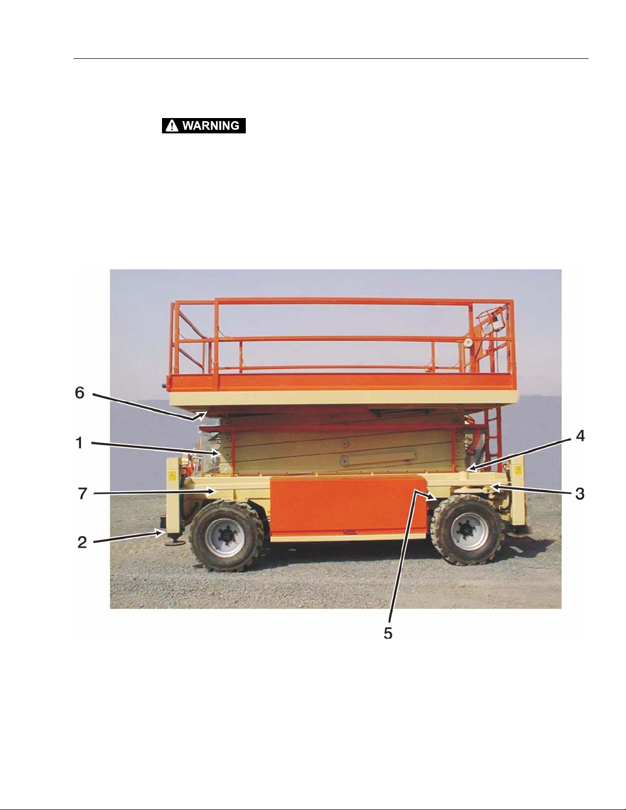
SECTION 2 - GENERAL
2.4 OPERATOR MAINTENANCE
TO AVOID PERSONAL INJURY, USE SAFETY PROPS FOR ALL MAINTENANCE REQUIRING PLATFORM TO BE ELEVATED.
NOTE: Be sure to lubricate like items on each side.
NOTE: Recommended lubricating intervals are based on machine operations under normal conditions. For machines used in
multi-shift operations and/or exposed to hostile environments or conditions, lubrication frequencies must be increased
accordingly.
Operate hydraulic functions through one complete cycle before checking hydraulic oil level in tank. Oil should be visible
in ADD sight window on hydraulic tank. If oil is not visible, add oil until oil is visible in both ADD and FULL sight windows
on tank. Do not overfill tank.
1. Arm Pins
2. Outrigger Cylinders
3. Tie Rod Ends
4. Spindles
5. Lift Cylinder
6. Upper Slide Pads
Figure 2-1. Lubrication Diagram
7. Lower Slide Pads
8. Engine Compartment (opposite side not shown)
9. Fuel Tank (opposite side not shown)
3121322 – JLG Lift – 2-5
Page 26
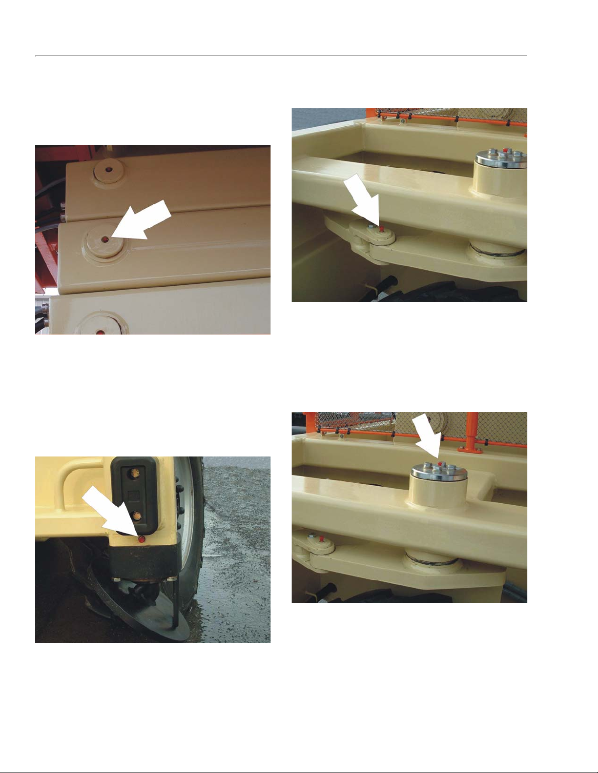
SECTION 2 - GENERAL
NOTE: The following numbers correspond with those in Fig-
ure 2-1., Lubrication Diagram.
1. Arm Pins
• Lube Points - 39 Grease Fittings
• Capacity - As Required
3. Tie Rod Ends
• Lube Points - 2 Grease Fittings
• Capacity - As Required
•Lube -MPG
• Interval - As Required
•Lube - MPG
• Interval - As Required
2. Outrigger Cylinders
• Lube Points - 4 Grease Fittings
• Capacity - As Required
4. Spindles
• Lube Points - 2 Grease Fittings
• Capacity - As Required
•Lube - MPG
• Interval - As Required
•Lube - MPG
• Interval - As Required
2-6 – JLG Lift – 3121322
Page 27
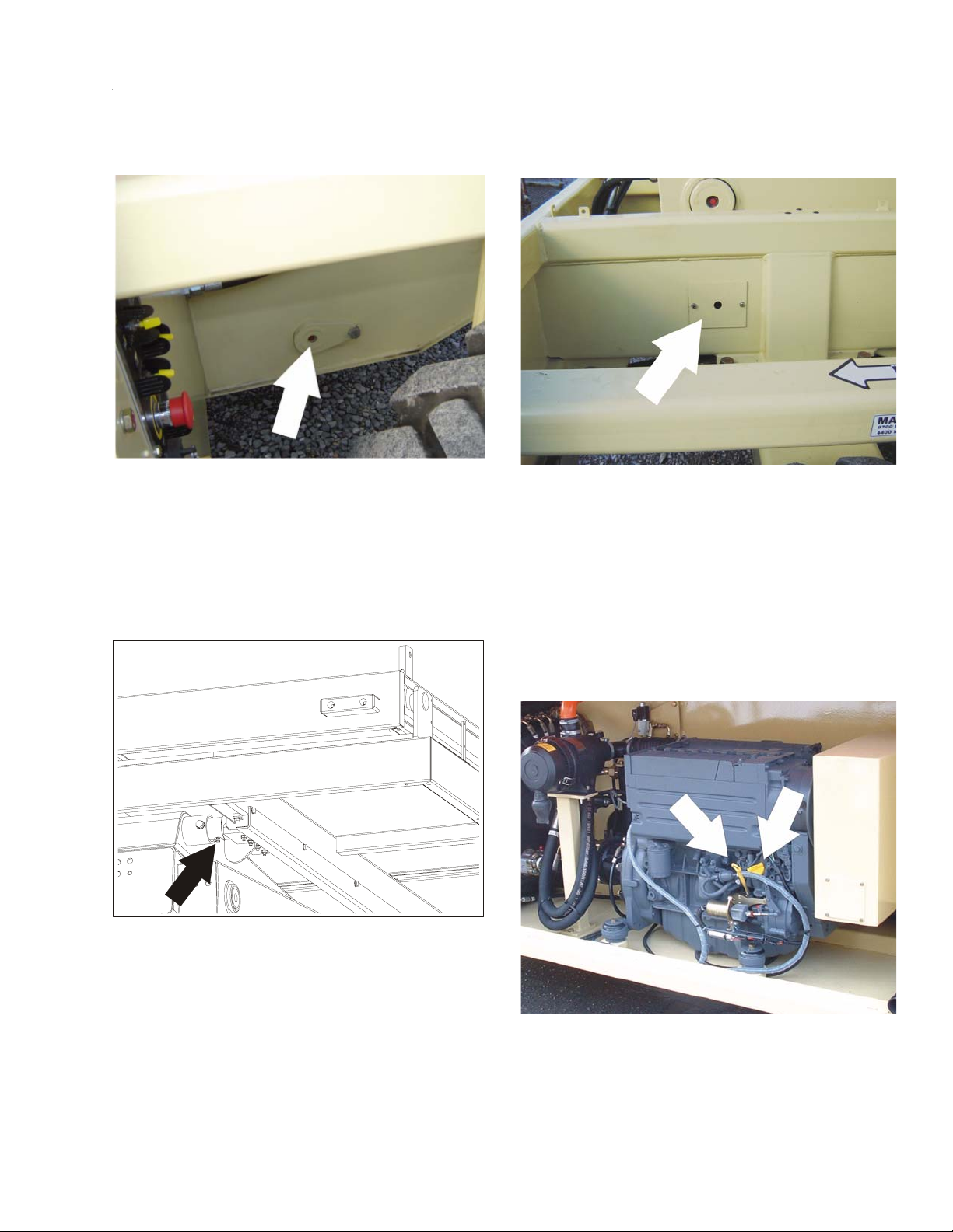
SECTION 2 - GENERAL
5. Lift Cylinder
• Lube Points - 2 Grease Fittings
• Capacity - As Required
•Lube - MPG
• Interval - As Required
7. Lower Slide Pads
• Lube Points - 2 Grease Fittings
• Capacity - As Required
•Lube - MPG
• Interval - As Required
6. Upper Slide Pads
• Lube Points - 2 Grease Fittings
• Capacity - As Required
•Lube - MPG
• Interval - As Required
8. Engine Compartment
a. Engine Oil Check/Fill
• Lube Points - Fill Cap & Dip Stick
• Capacity - See Engine Manual
• Lube - EO SAE 20W20
• Interval - Every 3 months or 150 hours of operation
3121322 – JLG Lift – 2-7
Page 28
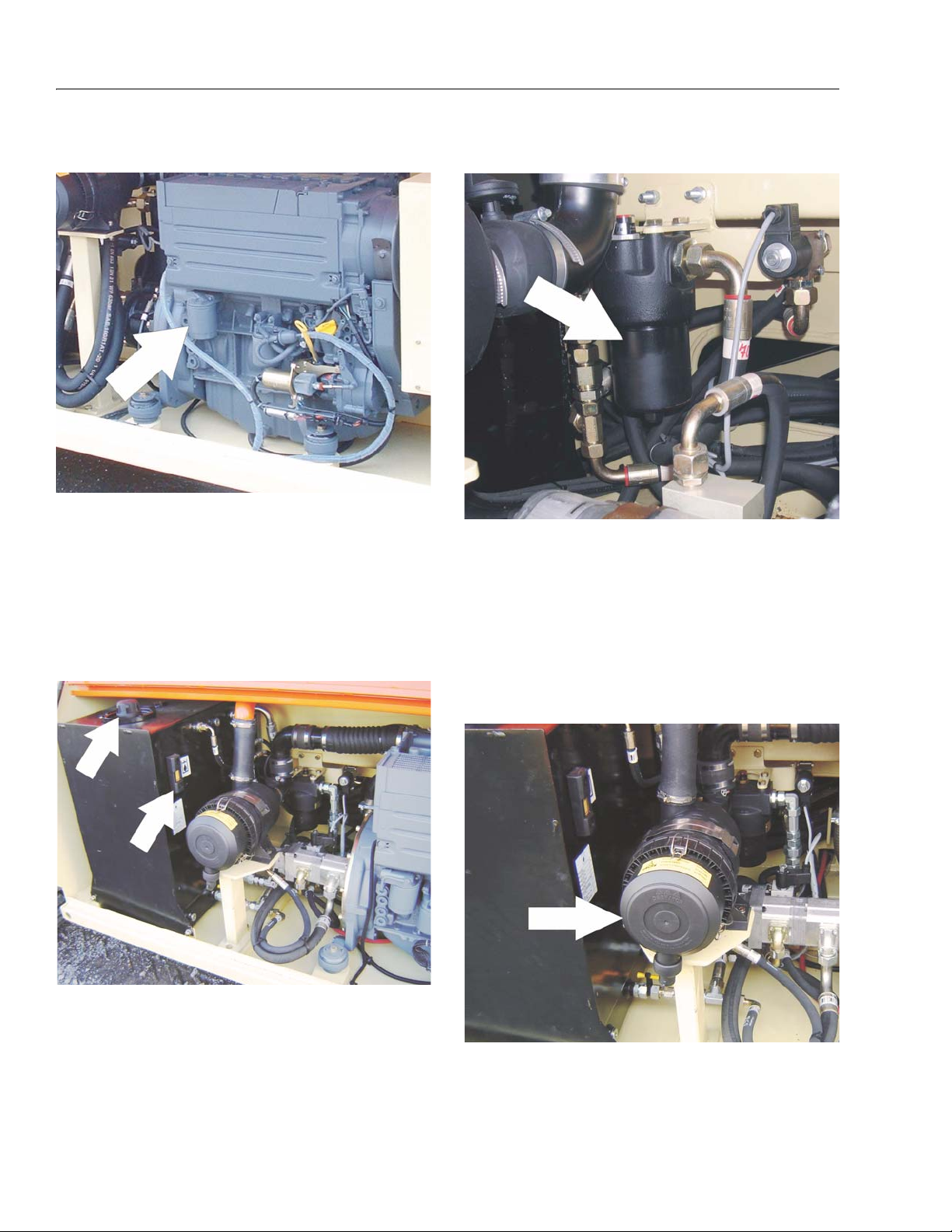
SECTION 2 - GENERAL
b. Oil Filter
• Maintenance - Replaceable Element
(JLG P/N 7016331)
• Interval - Change every 500 hours or 6 months, whichever comes first. Change filter every time engine oil is
changed.
c. Hydraulic Oil Check/Fill
d. Hydraulic Oil Filter
• Maintenance - Replaceable Element
(JLG P/N 70000899)
• Interval - 250 hours
• Comments - Change after first 50 hours, then every
250 hours of operation thereafter
• Lube Points - Fill Cap & Site Gauge
• Capacity - 35.7 gal (135 L)
•Lube - HO
• Interval - Check oil daily, change every 1200 hours of
operation
e. Air Filter
• Lube Points - Replaceable Element
(JLG P/N H005232 & 70000054)
• Interval - Every 6 months or 300 hours of operation
2-8 – JLG Lift – 3121322
Page 29
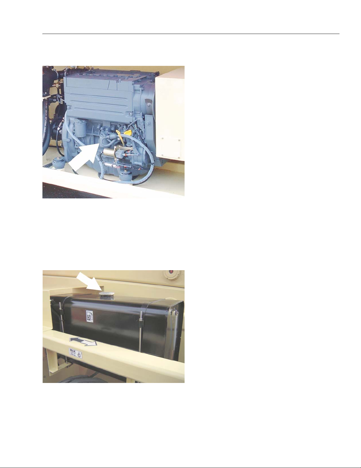
SECTION 2 - GENERAL
f. Fuel Filter
• Maintenance - Replaceable Element
(JLG P/N 7020023)
• Interval - Change every year or 600 hours of operation,
whichever comes first.
2.5 CYLINDER DRIFT TEST
Maximum acceptable cylinder drift is to be measured
using the following method.
Lift Cylinder Drift
NOTE: Test cylinder drift with machine oil at ambient tem-
perature.
1. Place maximum work load onto platform (Refer to
Table 1-1, Operating Specifications).
2. Extend lift cylinder to achieve a platform height 3 to
5 meters from fully stowed.
3. Wipe cylinder rod clean and place a mark on the rod
50mm from the cylinder head.
4. Wait 15 minutes.
5. Measure distance of mark from head.
6. Difference (cylinder drift) must not exceed 3mm.
NOTE: If cylinder drift exceeds 3mm, repeat test. If still
greater than 3mm, check holding valve (refer to Figure 4-41., Lift/Lower Valve Block). If still greater than
3mm, replace cylinder seals (refer to Section 4.4,
Cylinder Repair).
9. Fuel Tank
• Capacity - 23.8 gal (90 L)
• Lube - Diesel Fuel
• Interval - Check fuel periodically during each use
3121322 – JLG Lift – 2-9
Page 30

SECTION 2 - GENERAL
2.6 PREVENTIVE MAINTENANCE AND INSPECTION SCHEDULE
The preventive maintenance and inspection checks are
listed and defined in the following table. This table is
divided into two basic parts, the “AREA” to be inspected
and the “INTERVAL” at which the inspection is to take
place. Under the “AREA” portion of the table, the various
systems along with the components that make up that
system are listed. The “INTERVAL” portion of the table is
divided into five columns representing the various inspection time periods. The numbers listed within the interval
column represent the applicable inspection code for
which that component is to be checked.
The checks and services listed in this schedule are not
intended to replace any local or regional regulations that
may pertain to this type of equipment nor should the lists
be considered as all inclusive. Variances in interval times
may occur due to climate and/or conditions and depending on the location and use of the machine.
NOTICE
JLG INDUSTRIES REQUIRES THAT A COMPLETE ANNUAL
INSPECTION BE PERFORMED IN ACCORDANCE WITH THE
"ANNUAL MACHINE INSPECTION REPORT" FORM.
6. Check for presence of excessive dirt or foreign
material.
7. Check for proper operation and freedom of movement.
8. Check for excessive wear or damage.
9. Check for proper tightness and adjustment.
10. Drain, clean and refill.
11. Check for proper operation while pump/motor is
running.
12. Check for proper lubrication.
13. Check for evidence of scratches, nicks or rust and
for straightness of rod.
14. Check for condition of element; replace as necessary.
15. Check for proper inflation.
NOTE: This machine requires periodic safety and mainte-
nance inspections by a JLG Dealer. Notify dealer if
inspection is overdue.
The inspection and maintenance code numbers are as follows:
1. Check for proper and secure installation.
2. Check for visible damage and legibility.
3. Check for proper fluid level.
4. Check for any structural damage; cracked or broken
welds; bent or warped surfaces.
5. Check for leakage.
2-10 – JLG Lift – 3121322
Page 31

SECTION 2 - GENERAL
Table 2-3. Preventive Maintenance and Safety Inspection
AREA INTERVAL
Daily Weekly
PL AT F OR M
1. Controller 1,11
2. Switches 1,11
3. Placards and Decals 1,2
4. Control Tags 1,2
5. Hoses and Cables 4,8
6. Wear Pads 8,12
7. Handrails and Chains 1,4
CH A SS I S
1. Battery 3 5
2. Hydraulic Pump 1 5
3. Valves 1 5
4. Hydraulic Filter ANNUAL
5. Hydraulic Hoses and Tubing 1 5
6. Hydraulic Oil Tank 5 3,4
8. Lift Cylinder 1,12 5,6,13 4
9. Limit Switch 1,7
10. Tilt Alarm Switch 1,7
11. Placards and Decals 1,2
12. Wheel and Tire Assemblies 1 8,9
13. Drive Motors 1,5,6
14. Drive Brakes 1,6 8
15. Drive Torque Hubs 1,3,5,6
16. Steer Cylinder 1 5,6,13 4
17. Steer Components 1 4,6 8
18. Wheel Bearings 812
19. Scissor Arms 1,4
20. Safety Props 1,4
21. Sliding Wear Pads 8,12
22. Pivot Pins/Bolts 1,4 7,8
23. Switches, Ground Control 1,11
24. Control Tags 1,2
100 Hours
(3 Months)
200 Hours
(6 Months)
400 Hours
(1 year)
3121322 – JLG Lift – 2-11
Page 32

SECTION 2 - GENERAL
NOTES:
2-12 – JLG Lift – 3121322
Page 33

SECTION 3 - CHASSIS, PLATFORM & SCISSOR ARMS
SECTION 3. CHASSIS, PLATFORM & SCISSOR ARMS
3.1 OPERATING CHARACTERISTICS
NOTICE
ANYTIME SERVICING OF ELECTRICAL OR HYDRAULIC COMPONENTS IS REQUIRED, DISCONNECT BATTERY VIA THE DISCONNECT SWITCH ON THE GROUND CONTROL PANEL AND SHUT
VALVE LEVERS AT THE BASE OF THE HYDRAULIC TANK TO
STOP FLOW OF HYDRAULIC FLUID.
Leveling Jacks
The machine is equipped with auto leveling jacks. The
automatic self leveling system is controlled by 4 double
acting cylinders mounted at each corner of the machine
chassis. These cylinders incorporate pilot operated holding valves on the piston side. The cracking pressure of
these valves is 15 psi (1 bar) for the rear and 116 psi (8
bar) for the front.
1. Activate the leveling jack switch located on the
ground control console.
2. Extend the jacks by moving the joystick on the platform control box forward.
NOTE: The jacks deploy at idle engine speed. Once all four
jacks make contact with the ground the system will
go from set mode into level mode. Once level,
engine rpm’s will increase and lift is allowed.
3.2 WHEEL ASSEMBLY
Drive System
Wheel drive is achieved by orbital type (100cc/rev)
hydraulic motors driving a wheel type gearbox (29.8:1
reduction) through a spring-applied brake.
The brake is released by actuating a 3 way solenoid valve.
This valve provides hydraulic power from the pump
directly to the brakes. The brake can be reset by deactivating the valve and restricting flow to the tank through an
orifice to smooth out hard stops. Drive is controlled by a
proportional solenoid valve section within the main control
valve (see Figure 4-33.).
Flow to the drive motors passes through a series /parallel
solenoid. When all 3 solenoids are in the passive (nonenergised) mode, flow is split by 3 flow dividers:
•Front/Rear
• Rear - Left/Right
• Front - Left/Right
When the solenoids are activated, all ports on the rear
hydraulic motors are connnected so that they free the
wheel. The front motors are connected in series (output of
one motor to the input of the other) to enable fast drive
low torque mode.
3. The tilt indicator LED’s on the Main Terminal Box will
go out once the machine is level.
NOTE: There are limit switches mounted at each jack cyli-
inder. These sense when the jack makes ground
contract and enable the lift function. All four switches
must have contact (lift indicator LED on the platform
will light) to enable lift. When elevated, if a contact
signal is lost (jack loses ground contact, wire cut,
etc.), the lift function is stopped and only lowering is
permitted.
The jacks are operational (extend or retract) if the
machine is in the stowed position. The minimum
height limit switch must sense the machine is
stowed. A failure of the limit switch will prevent the
jacks from being activated.
NOTE: Refer to Section 5.3, Nivolux - Automatic Self-Level-
ing System for detailed information regarding the
automatic leveling system.
3121322 – JLG Lift – 3-1
Page 34

SECTION 3 - CHASSIS, PLATFORM & SCISSOR ARMS
Drive Hub
NOTICE
DRIVE HUB UNITS SHOULD ALWAYS BE ROLL AND LEAK
TESTED BEFORE DISASSEMBLY AND AFTER ASSEMBLY TO
MAKE SURE THAT THE UNIT’S GEARS AND SEALANTS ARE
WORKING PROPERLY.
The following information briefly outlines what to look for
when performing these tests.
IF THE MACHINE IS ON ANY INCLINE, THE WHEELS MUST BE
ADEQUATELY BLOCKED PRIOR TO MANUALLY DISENGAGING
THE BRAKES. FAILURE TO DO SO MAY RESULT IN INJURY OR
EVEN DEATH.
Roll Test
The purpose of the roll test is to determine if the unit's
gears are rotating freely and properly. You should be able
to rotate the wheel or hub of the gearbox by hand. If you
feel more drag in the gears only at certain points, then the
gears are not rolling freely and should be examined for
improper installation or defects. Some gear packages roll
with more difficulty than others. Do not be concerned if the
gears in your unit seem to roll hard as long as they roll
with consistency.
1
2
4
3
1. Drive Hub
2. Screw
3. Circlip
4. Pin
Figure 3-1. Drive Hub
Hub Disengaging and Oil Checking Procedure:
Leak Test
The purpose of a leak test is to make sure the unit is air
tight. You can tell if your unit has a leak if the pressure
gauge reading on your leak checking fitting starts to fall
after the unit has been pressurized and allowed to equalize. Leaks will most likely occur at the pipe plugs, the main
seal or wherever o-rings are located. The exact location of
a leak can usually be detected by brushing a soap and
water solution around the main seal and where the o-rings
or gaskets meet on the exterior of the unit, then checking
for air bubbles. If a leak is detected in a seal, o-ring or gasket, the part must be replaced, and the unit rechecked.
Leak test at 10 psi for 20 minutes.
NOTE: Due to the small air volume inside this Torque-Hub, it
will pressurize to 10 psi very quickly. If the pressure
becomes excessive in the unit the seals will be
destroyed.
Lubricant
The torque hub unit is shipped with 90W gear oil. It is
designed to utilize the same oil throughout its service life.
However, should it need to be serviced the oil will need to
be drained and replaced.
In the event of servicing, fill the unit with Arco H.D. 120#
Drum or Exxon GX 80W-90.
1. Loosen the two Screws (2) securing the Circlip (3).
2. Slide the Circlip (3) in the direction of the arrow.
3. Remove the Pin (4).
4. The proper gear oil level should be to the base of the
opening. Add gear oil if needed.
5. Turn the Pin (4) around and place back onto Hub
(1).
NOTE: Side of Pin that was facing outside should now be
facing the inside of the hub.
6. Slide Circlip (3) in opposite direction of arrow to
secure the Pin. Tighten Screws (2) to secure the Circlip in place.
3-2 – JLG Lift – 3121322
Page 35

SECTION 3 - CHASSIS, PLATFORM & SCISSOR ARMS
Table 3-1. Drive Hub Technical Specifications
Max Torque 5,5 kNm
Max Input Speed 4000 rpm
Weight
Brake
Static Torque
Releas ing Pressur e
Max Pressure
Max Input Torque
101.4 lbs
(46 kg)
147.5 lb ft
(200 Nm)
174-217.5 psi
(12-15 bar)
1450.3 psi
(100 bar)
147.5 lb ft
(200 Nm)
Tire Replacement
JLG recommends a replacement tire be the same size, ply
and brand as originally installed on the machine. Please
refer to the JLG Parts Manual for the part number of the
approved tires for a particular machine and model. If not
using a JLG approved replacement tire, it is recommended that replacement tires have the following characteristics:
• Equal or greater ply/load rating and size of original.
• Tire tread contact width equal or greater than original.
• Wheel diameter, width, and offset dimensions equal to
the original.
WHEEL NUTS MUST BE INSTALLED AND MAINTAINED AT THE
PROPER TORQUE TO PREVENT LOOSE WHEELS, BROKEN
STUDS, AND POSSIBLE DANGEROUS SEPARATION OF WHEEL
FROM THE AXLE. BE SURE TO USE ONLY THE NUTS MATCHED
TO THE CONE ANGLE OF THE WHEEL.
Tighten the lug nuts to the proper torque to prevent
wheels from coming loose. Use a torque wrench to
tighten the fasteners. If you do not have a torque
wrench, tighten the fasteners with a lug wrench, then
immediately have a service garage or dealer tighten
the lug nuts to the proper torque. Over-tightening will
result in breaking the studs or permanently deforming
the mounting stud holes in the wheels. The proper procedure for attaching wheels is as follows:
1. Start all nuts by hand to prevent cross threading. DO
NOT use a lubricant on threads or nuts.
2. Tighten nuts in the following sequence:
6
1
3
5
4
2
Unless specifically approved by JLG Industries, Inc. do
not replace a foam filled tire assembly with a pneumatic
tire. When selecting and installing a replacement tire,
ensure that all tires are inflated to the pressure recommended by JLG. Due to size variations between tire
brands, both tires on the same axle should be the same.
NOTE: Tires are foam filled to 90 psi (6.2 bar).
3. The tightening of the nuts should be done in stages.
Following the recommended sequence, tighten the
nuts per wheel torque chart.
Wheelnut Tightening Pattern
Wheel Replacement
The rims installed on each product model have been
designed for stability requirements which consist of track
width, tire pressure, and load capacity. Size changes such
as rim width, center piece location, larger or smaller diameter, etc., without written factory recommendations, may
result in an unsafe condition regarding stability.
NOTICE
IT IS EXTREMELY IMPORTANT TO APPLY AND MAINTAIN
PROPER WHEEL MOUNTING TORQUE.
1st Stage 2nd Stage 3rd Stage
150-190 ft lbs
(210 - 270 Nm)
4. Wheel nuts should be torqued after the first 50 hours
of operation and after each wheel removal. Check
torque every 3 months or 150 hours of operation.
3121322 – JLG Lift – 3-3
TORQUE SEQUENCE
230 - 270 ft lbs
(320-380 Nm)
305 - 343 ft lbs
( 440 - 480 Nm)
Page 36

SECTION 3 - CHASSIS, PLATFORM & SCISSOR ARMS
1. Wheelnut (6 per wheel)
2. Drive Hub
3. Bolt, M16 x 55mm (8 per wheel)
4. Hardened Washer (8 per wheel)
5. Drive Motor
8
5
3
4
6
7
2
1
Figure 3-2. Wheel Assembly Removal
SECURE MACHINE WITH JACKS AND CHALK BLOCKS WHEN
REMOVING AND/OR INSTALLING WHEELS.
NOTE: Follow the below steps when servicing/replacing the
wheel/tire assembly.
Removal:
1. Elevate machine with jacks or other suitable device
and secure.
2. Remove 6 Wheelnuts (1).
6. Bolt, M12 x 35mm (2 per wheel)
7. Lockwasher, M12 (2 per wheel)
8. Spindle
3. Carefully remove tire from Drive Hub (2).
4. Disconnect all hoses/wires from Drive Motor (5).
5. Remove two Bolts (6) and Lockwashers (7) attaching the Drive Motor to the Drive Hub. Carefully
remove the Drive Motor.
6. Remove the eight Bolts (3) and Hardened Washers
(4) attaching the Drive Hub to the Spindle (8). Carefully remove the Drive Hub.
Installation:
• Follow the removal steps in reverse order when installing the wheel assembly.
3-4 – JLG Lift – 3121322
Page 37

SECTION 3 - CHASSIS, PLATFORM & SCISSOR ARMS
1
Drive Motor Side
2
1. Torque to 354 lb ft Dry (480 Nm)
2. Torque to 230.9 lb ft Dry (313 Nm)
Figure 3-3. Hub Torque Values
3121322 – JLG Lift – 3-5
Page 38

SECTION 3 - CHASSIS, PLATFORM & SCISSOR ARMS
42
11
24
32
10
23
27
132312
25
22
45
28
36
37
15
16
48 2
35
21
31
46
40
6
17
49
183938
7
12
1
47 41
11
9
26
4
1. Spindle
2. Hub
3. Gear Ring
4. Cover
5. Flange
6. Coupling
7. Thrust Washer
8. Thrust Washer
9. Circlip
10. Planetary Gear
11. Pin
12. Thrust Washer
13. Spacer
29
43
44
3
14. Sun Pinion
15. Piston
16. Spring
17. Disc
18. Disc
19. Lock Nut
20. Bearing
21. Bearing
22. Bearing
23. Bearing
24. Circlip
25. Circlip
26. Disc
52
14
19
27. Circlip
28. Plug
29. O-Ring
30. O-Ring
31. O-Ring
32. O-Ring
33. O-Ring
34. Oil Seal
35. Gasket
36. O-Ring
37. Blocking Ring
38. O-Ring
39. Blocking Ring
Figure 3-4. Drive Hub Assembly
20
30
2
20
40. Screw
41. Screw
42. Screw
43. Plug
44. Washer
45. Plug
46. Disc
47. Threaded Stud
48. O-Ring
49. Reduction Gear Kit
34
3-6 – JLG Lift – 3121322
Page 39

Drive Motor
SECTION 3 - CHASSIS, PLATFORM & SCISSOR ARMS
2
1
3
45
67
8
1. Dust Seal
2. Motor Housing
3. Shaft Seal
4. Bearing Race
5. Axel Needle Bearing
Displacement
Max Speed 600 rpm
Max Torque
Max Power 13 kw
Max Oil Flow
98 10 8 1112
6. Output Shaft
7. Cardan Shaft
8. O-Ring
9. Distributor Plate
10. Gear Wheel Set
Figure 3-5. Drive Motor (OMR 100)
Table 3-2. Drive Motor Specs
3
99.8 cm
177 lb ft
(240 Nm)
15.9 gal/min
(60 L/min)
13
11. End Cover
12. Washer
13. Screw
3121322 – JLG Lift – 3-7
Page 40

SECTION 3 - CHASSIS, PLATFORM & SCISSOR ARMS
Motor Disassembly
NOTE: For numbers in ( ), refer to Figure 3-5., Drive Motor
(OMR 100).
1. Place the Motor Housing (2) in a holding tool with
the flange upwards.
2. Use a 13mm spanner socket to remove the screws
(13) and washers (12).
3. Remove the End Cover (11) sideways.
4. When removing the Gear Wheel Set (10) and two ORings (8), keep fingers under the the gear wheel set
to prevent the parts from falling out.
5. Remove the Cardan Shaft (7).
6. Remove the Distributor Plate (9) and O-Ring (8).
7. To remove the Output Shaft (6), place the motor
housing (2) on a work bench and press the shaft out
of the motor housing.
8. Remove the Bearing Race (4) from the motor housing (2).
9. Remove the Axel Needle Bearing (5).
10. With a mandrel and plastic hammer, carefully knock
out the Shaft Seal (3) and Dust Seal Ring (1).
NOTE: When cleaning parts, clean parts carefully with low
aromatic kerosine.
Check all parts carefully and replace if necessary.
Before assembly, lubricate all parts with hydraulic oil
and grease rubber parts with vaseline.
Motor Assembly
1. Place the Motor Housing (2) in a holding tool with
the flange upwards.
2. Lubricate the Shaft Seal (3) on the outside with
hydraulic oil. Fit the shaft seal correctly onto the
mandrel and carefully press the shaft seal into position into the motor housing.
3. Place the Dust Seal Ring (1) in the spigot flange and
knock it into position with a plastic hammer and
appropriate mandrel.
4. Fit the Bearing Race (4) onto the shaft and mount
together with the shaft.
5. Place the Axel Needle Bearing (5) back onto shaft.
6. Output Shaft (6): Grease the journals with hydraulic
oil. The rear shaft end must be marked before fitted.
The mark must be positioned vertically above a
commutation slot leading up to the front annular
channel.
7. Grease the O-Ring (8) and put it in the O-ring groove
of the housing.
8. Turn the Distributor Plate (9) so that the holes line
up.
9. Guide the Cardan Shaft (7) down into the motor
housing. In case of different splines lengths turn the
cardan shaft to ensure the long splines end is fitted
in the output shaft. Transfer marking from output
shaft to cardan shaft.
10. Place the two O-Rings (8) (greased) in the O-ring
grooves of the Gearwheel. In gearwheels with non
through splines place the gearwheel with the recess
in the spline hole facing down towards the housing.
Place the Gear Wheel Set (10) on the cardan shaft
so that the top of a tooth in the external teeth of the
gearwheel are vertically above the mark on the cardan shaft. Turn the gearwheel set counterclockwise
until the cardan shaft and the gearwheel start to
mesh (15°). Turn the gearwheel rim so that the holes
made for the screws line up.
11. Turn the End Cover (11) so that the holes line up.
12. Place the Washers (12) onto the Screws (13). Use a
13mm spanner socket to tighten the screws..
Table 3-3. Tightening Torques
Item Tor que
Screws (item 13 in Figure 3-5.)
270 - 315 lbf in
(3.0 - 3.5 daNm)
3-8 – JLG Lift – 3121322
Page 41

3.3 STEERING ASSEMBLY
SECTION 3 - CHASSIS, PLATFORM & SCISSOR ARMS
31
32
33
1. Right Spindle
2. Left Spindle
3. Cap
4. Grease Fitting Cap
29
30
19
10. Bushing*
11. Ring
12. Pin
13. Grease Fitting Cap
18
1
20
22
23
24
25
21
26
17
15
16
13
14
12
28
27
19. Steer Cylinder
20. Bolt, M12 x 150mm
21. Flatwasher, M12
22. Washer
2
10
6
7
3
8
9
11
4
5
28. Grease Fitting
29. Grease Fitting Cap
30. Grease Fitting
31. Bolt, M12 x 20mm
5. Grease Fitting
6. Bolt, M12 x 30mm
7. Lockwasher, M12
8. O-Ring
9. Ring
NOTE: * = not used on all machines.
Remove wheel and tire assemblies before attempting to service the steering assembly. Disconnect
electrical supply and any wires and/or hoses.
Secure machine with proper stabilizing devices.
Removal:
1. Remove Steer Cylinder (19) by removing Bolts (20,
31), Washers (21, 22, 23, 32), Nuts (25) and Pins
(26, 33).
14. Grease Fitting
15. Bolt, M12 x 20mm
16. Lockwasher, M12
17. Bushing
18. Tie Bar
Figure 3-6. Steering Assembly
23. Washer
24. Flatwasher, M12
25. Nut, M12
26. Pin
27. Grease Fitting Cap
2. Disconnect Tie Bar (18) from both Spindles (1, 2) by
removing Bolts (15), Lockwashers (16), Pins (12),
and Bushings (17). Remove Tie Bar.
3. Spindles can now be removed from the chassis.
Secure Spindle. Remove Grease Cap (4) and Fitting
(5). Remove Bolts (6), Lockwashers (7), Cap (3), ORing (8), Ring (9), and Bushings* (10). The Spindle
can now be removed for repair/replacement.
Installation:
1. Follow the Removal Steps in reverse order when
assembling the steering system.
32. Lockwasher, M12
33. Pin
3121322 – JLG Lift – 3-9
Page 42

SECTION 3 - CHASSIS, PLATFORM & SCISSOR ARMS
3.4 REAR AXLE ASSEMBLY
1. Rear Axle Weldment
2. Bolt, M20 x 65mm
3. Nut, M20
4. Hardened Washer
2
4
4
3
Figure 3-7. Rear Axle Removal
NOTICE
SECURE THE MACHINE AND AXLE WELDMENT WHEN SERVICING/REMOVING. THE AXLE WEIGHS APPROXIMATELY 325 LBS
(147.5 KG).
NOTE: Remove the tire and wheel assemblies before
removing the axle. (Refer to Figure 3-2., Wheel
Assembly Removal).
Removal:
1. Remove the eight Bolts (2), Nuts (3), and sixteen
Hardened Washers (4) attaching the Rear Axle
Weldment (1) to the frame.
2. Carefully remove the Rear Axle.
1
Installation:
1. Raise Axle to the frame.
2. Secure the axle to the frame using the eight Bolts
(2), Nuts (3), and sixteen Hardened Washers (4).
3. Torque Bolts to 450 lb ft (610 Nm) dry.
3-10 – JLG Lift – 3121322
Page 43

3.5 OUTRIGGER CYLINDER REMOVAL
2
A
3
B
1
SECTION 3 - CHASSIS, PLATFORM & SCISSOR ARMS
5
6
9
8
7
4
1. Cover
2. Bolt, M8 x 160mm
3. Lockwasher, M8
4. Outrigger Cylinder
5. Bolt, M8 x 50mm
6. Lockwasher, M8
7. Valve Assembly
8. Limit Switch Bracket
Figure 3-8. Outrigger Cylinder Removal - (Sheet 1 of 2)
NOTE: Refer to Figure 3-8., Outrigger Cylinder Removal -
(Sheet 1 of 2) and Figure 3-9., Outrigger Cylinder
Removal - (Sheet 2 of 2).
Shut off flow of hydraulic oil before attempting to
remove any outrigger cylinder.
Removal:
A )
1. Remove the Cover (1) by removing the four Bolts (2)
and Lockwashers (3).
B )
2. Disconnect all hydraulic hoses and wires attached to
the Valve Assembly (7) and Limit Switch (9).
3. Remove the Valve Assembly, Limit Switch Bracket
(8) and Limit Switch from the top of Outrigger Cylinder (4) by removing the four Bolts (5) and Lockwashers (6)
9. Limit Switch
NOTE: Support cylinder rod to prevent rod extension and
consequential oil spillage.
After "Removal Step #3," the frame must be elevated
greater than the length of the stowed outrigger cylinder to remove the cylinder.
C )
4. Remove the Plate (12) and Gasket (13) by removing
the four Bolts (10) and Lockwashers (11).
5. Secure the Outrigger Cylinder (16). Remove the four
Bolts (14) and Lockwashers (15) attaching the cylinder to the frame.
D )
6. Carefully lower the Cylinder out of the frame.
3121322 – JLG Lift – 3-11
Page 44

SECTION 3 - CHASSIS, PLATFORM & SCISSOR ARMS
10
C
11
12
D
16
16
13
15
14
10. Bolt, M6 x 16mm
11. Lockwasher, M6
12. Plate
13. Gasket
Figure 3-9. Outrigger Cylinder Removal - (Sheet 2 of 2)
Installation:
1. Carefully insert Outrigger Cylinder (16) back into the
frame and secure with the four Bolts (14) and Lockwashers (15).
2. Replace Gasket (13) and Plate (12). Secure with four
Bolts (10) and Lockwashers (11).
NOTE: At this point the frame may be lowered.
3. Place Valve Assembly (7), Limit Switch Bracket (8),
and Limit Switch (9) back onto the top of the cylinder
and secure with the four Bolts (5) and Lockwashers
(6).
4. Reconnect all hydraulic lines and electrical wires.
14. Bolt, M12 x 70mm
15. Lockwasher, M12
16. Outrigger Cylinder
5. Return flow of hydraulic oil and ensure there is no
leakage. Operate cylinder to ensure it works properly.
6. Replace Cover (1) and secure with four Bolts (2) and
Lockwashers (3).
3-12 – JLG Lift – 3121322
Page 45

3.6 ENGINE COMPARTMENT
Hood Assembly
13
14
7
8
15
13
14
15
16
2
9
2
10
11
12
3
6
ENGINE SIDE
5
16
4
SECTION 3 - CHASSIS, PLATFORM & SCISSOR ARMS
VALVE SIDE
1. Hood
2. Gas Spring
3. Bolt M8 x 30mm
4. Nut M8
5. Cabinet Top Panel (Left)
6. Cabinet Panel (Right)
15
13
14
15
8
7
2
7. Special Bolt
8. Flatwasher M12
9. Air Intake Pipe
10. Bolt M8 x 25mm
11. Flatwasher M8
12. Locknut M8
13. Bolt M10 x 25mm
14. Nut M10
15. Flatwasher M10
1
Figure 3-10. Hood Assembly
NOTE: Removing the hoods will allow for easier access to
the components inside the engine compartment and
valve compartment.
1. Open and secure Hood (1).
2. Remove Bolt (3) and Nut (4) on both Gas Springs
(2). Return Hood to closed position.
3. Remove both Bolts (7) and Flatwashers (8) connecting hoods to the Cabinet Top Panel (5 & 6).
16. Nut M10
NOTE: Step 4 applies only to the Engine Side Compart-
ment.
4. Remove the Air Intake Pipe (9) by removing the four
Bolts (10), Flatwashers (11), and Locknuts (12).
5. Remove the Cabinet Top Panel (5 & 6) by removing
the 4 Bolts (13), eight Flatwashers (14), and four
Nuts (16).
NOTE: Follow the steps in reverse order to re-attach the
hood and top panel.
3121322 – JLG Lift – 3-13
Page 46

SECTION 3 - CHASSIS, PLATFORM & SCISSOR ARMS
2
Deutz Engine
1. Deutz F3L2011
2. Hydraulic Tank
3
4
1
3. Air Filter
4. Hydraulic Pump
Figure 3-11. Deutz Engine
Table 3-4. Engine Technical Data
Description F3L 2011F D2011 L03 i
Fuel Diesel
Number of Cylinders 3
Cylinder Arrangement Vertical In Line
Bore 3.7 in (94 mm)
Stroke 4.4 in (112 mm)
To ta l D i sp l ac e me nt
Engine Speed:
H ig h
L ow
Swept Volume 2331 cm³
Vol tag e 24 Volt s
140.4 in
2300l/min
850 l/min
3
( 2. 3 L)
3-14 – JLG Lift – 3121322
Page 47

Engine Tray Slide
SECTION 3 - CHASSIS, PLATFORM & SCISSOR ARMS
3
1, 2
1. Bolt, M16 x 30mm
2. Lockwasher, M16
3. Bolt, M16 x 60mm
Figure 3-12. Engine Tray Slide
The engine tray can be slide outward approximately 5.9
in. (15 cm) when servicing components inside the engine
compartment.
1. Remove the two Bolts (1) and Lockwashers (2) on
the front of the engine tray.
2. Loosen the two top Bolts (3) at both ends of the
engine compartment. Slide engine tray outward.
3. Be sure to return engine tray to stowed position
when finished servicing. Secure engine tray with the
two front Bolts (1) and Lockwashers (2) and two top
Bolts (3).
3
1, 2
3121322 – JLG Lift – 3-15
Page 48

SECTION 3 - CHASSIS, PLATFORM & SCISSOR ARMS
Glow Plugs
1. 30 amp Fuses
2. Timer Relay N6
3. Relay K3
Engine Solenoid
Figure 3-13. Glow Plugs
1. Solenoid
2. 30 amp Fuse
Figure 3-14. Engine Solenoid
3-16 – JLG Lift – 3121322
Page 49

Gear Pump Assembly
3
4
SECTION 3 - CHASSIS, PLATFORM & SCISSOR ARMS
1. Hydraulic Pump
2. Bolt (M8 x 25mm) and
Lockwasher (M8)
5
3. Pump Mounting Flange
4. Capscrew (M8 x 25mm)
and Lockwasher (M10)
5. Coupling
2
1
Figure 3-15. Gear Pump Assembly
Removal:
1. Shut off flow of hydraulic fluid to the Pump (1).
2. Disconnect any hoses and/or wires attached to the
pump.
3. Remove the 4 Bolts and Lockwashers (2) connecting the pump to the Pump Mountng Flange (3).
Carefully remove the pump.
4. To remove the pump mounting flange, unscrew the
12 Capscrews and Lockwashers (4).
5. The Coupling (5) can be removed by unscrewing
the 6 Screws and Lockwashers (6).
Installation:
1. Follow the Removal steps in reverse order, installaing components as opposed to removing them.
3121322 – JLG Lift – 3-17
Page 50

SECTION 3 - CHASSIS, PLATFORM & SCISSOR ARMS
Figure 3-16. Gear Pump
Table 3-5. Gear Pump Specs.
FIRST STAGE
Displacement 22,8 cc/rev
Rated Pressure 2611 psi (180 bar)
Peak Pressure 2901 ps i (200 bar)
Maximum Speed 3000 rpm
Minimum Speed at Rated Pressure 1000 rpm
SECOND STAGE
Displacement 8,4 cc/rev
Rated Pressure 3626 ps i (250 bar)
Peak Pressure 4061 ps i (280 bar)
Maximum Speed 4000 rpm
Minimum Speed at Rated Pressure 1000 rpm
THIRD STAGE
Displacement 2 ,09 cc/rev
Rated Pressure 3626 ps i (250 bar)
Peak Pressure 3916 ps i (270 bar)
Maximum Speed 4000 rpm
Minimum Speed at Rated Pressure 1000 rpm
Operation
3 Sections to the pump:
• Section 1 (22.5cc/rev - 51 L/m) Main flow to control
valve
• Section 2 (8cc/rev - 18 L/m) Secondary flow to control
valve
• Section 3 (2cc/rev - 4.5 L/m) Flow to steering valve
Pump Flow
• Flow from the first 2 pump sections to the control valve
is protected by dump valves which normally open to
tank ports. To generate hydraulic power to the control
valve, the dump valves need to be activated. Section 1
valve for main flow and section 2 valve to enable high
drive speed.
3-18 – JLG Lift – 3121322
Page 51

Exhaust Pipe Assembly
SECTION 3 - CHASSIS, PLATFORM & SCISSOR ARMS
3
1
7
8
6
4
2
5
1. Muffler
2. Exhaust Clamp
3. Exhaust Elbow
NOTE: In the event any or all exhaust piping needs repaired
or replaced follow the below steps. Refer to Figure 3-
17., Exhaust Pipe Assembly.
1. Loosen the Exhaust Clamp (2) located on the muffler (2).
2. Slide the Exhaust Elbow (3) out of the muffler.
3. Loosen the Exhaust Clamp (4).
4. The exhaust elbow can now be removed.
5. Remove the Exhaust Flex Pipe (5) by loosening the
Exhaust Clamp (6). Slide the pipe out of the Tailpipe
(7).
6. The tail pipe can be removed by unscrewing the Bolt
(8) connecting it to the engine tray.
4. Exhaust Clamp
5. Exhaust Flex Pipe
6. Exhaust Clamp
Figure 3-17. Exhaust Pipe Assembly
7. Tailpipe
8. Bolt (M10 x 20mm) and Lockwasher (M10)
Installation:
1. Follow the steps in reverse order to assemble the
exhaust system. Take care to securely tighten the
exhaust clamps.
3121322 – JLG Lift – 3-19
Page 52

SECTION 3 - CHASSIS, PLATFORM & SCISSOR ARMS
Air Filter Assembly
17
16
15
14
13
12
9
8
7
11
10
6
5
2
18
19
1. Air Filter
2. Bolt, Nut, Flatwasher
3. Intake Hose
4. Hose Clamp
5. Hose Clamp
6. Hose Clamp
7. Reducing Sleeve
8. Hose Clamp
9. Air Intake Elbow
10. Hose Clamp
11. Air Intake Tube
4
3
1
12. Hose Clamp
13. Air Intake Elbow
14. Air Intake Tube
15. Hose Clamp
16. Intake Pipe
17. Hose Clamp
18. Rubber Intake Tube
19. Hose Clamp
Figure 3-18. Air Filter Assembly
NOTE: Refer to Figure 3-18. when dismantling the Air Filter
for service and/or replacements.
1. Removing the pipes and tubes requires loosening
the hose clamps. Once the hose clamps are loosened, the tubes and pipes can be removed for maintenance or replacement.
2. To remove the Air Filter (1), unscrew the 2 Bolts (2).
Remove the air cleaner from the bracket.
3. Lift the latches on the end of the Air Filter to access
the safety element (not shown).
NOTE: When assembling the air filter system, take care to
securely fit all tubing and piping together and to
securely tighten all hose clamps.
3-20 – JLG Lift – 3121322
Page 53

Engine Removal
SECTION 3 - CHASSIS, PLATFORM & SCISSOR ARMS
1
2
4
1
2
1. Bolt, M12 x 110 mm
2. Flatwasher, M12
3. Nut, M12
4. Oil Drain Port
1
2
2
3
2
3
2
3
Figure 3-19. Engine Removal
NOTE: Refer to Figure 3-19. when removing engine from
engine compartment.
ENGINE REMOVAL REQUIRES HEAVY LIFTING DEVICES. USE
EXTREME CAUTION WHEN REMOVING THE ENGINE.
1. Disconnect all electrical wires, hoses, pipes, etc.
2. Secure engine with appropriate lifting device. (Refer
to Deutz Operation Manual included with the
machine)
3. Remove 4 Nuts (3) and Flatwashers (2) from the
underside of the engine tray.
4. Remove all 4 Bolts (1) and second set of Flatwashers.
5. Carefully lift engine from engine compartment with
appropriate lifting device.
NOTE: When installing the engine, follow the steps in
reverse order.
The machine comes with an engine oil drain hose
(located in the plastic bag in the valve compartment)
to use when draining the oil from the engine.
Remove the cover on the Oil Drain Port (4). Attach
the drain hose to the Port. The valve on the hose
releases the valve on the Port to drain the oil. Run
the hose through the opening on the bottom of the
engine tray.
3121322 – JLG Lift – 3-21
Page 54

SECTION 3 - CHASSIS, PLATFORM & SCISSOR ARMS
Hydraulic Tank
5
2,
3,
4
1. Hydraulic Tank
2. Capscrew, M10 x 25mm
3. Flatwasher, M10 (2 per capscrew)
4. Nut, M10
5. Filler
6. Shutoff Valve Levers
1
Removal:
1. Shut the two valve levers (6) at the base of the tank
to turn off flow of hydraulic fluld. Drain hydraulic fluid
by opening the drain port on underside of the
Hydraulic Tank (1). Store fluid in appropriate receptacle. Disconnect all hoses.
2. Remove hydraulic tank by removing the four Capscrews (2), Nuts (4) and eight Flatwashers (3).
3. Carefully remove the tank from the engine compartment.
2, 3, 4
Figure 3-20. Hydraulic Tank Removal
Installation:
1. Place tank into engine compartment lining up the
bolt holes.
2. Replace Capscrews, Flatwashers and Nuts into their
respectable holes. Tighten.
3. Replace all hydraulic hoses.
4. Ensure the drain port is closed.
5. If required, replace Filter.
6. Remove Filler cap (5) and fill tank with hydraulic fluid
to its designated capacity, 37 gal (135 L).
7. Open valve lever to turn on flow of hydraulic fluid.
3-22 – JLG Lift – 3121322
Page 55

Pressure Filter
SECTION 3 - CHASSIS, PLATFORM & SCISSOR ARMS
2, 3
1. Pressure Filter 2. Capscrew, M10 x 20mm 3. Lockwasher, M10
1
Figure 3-21. Pressure Filter Removal
Removal:
1. Disconnect hose(s) from the Pressure Filter (1).
2. Loosen and remove the four Capscrews (2) and
Lockwashers (3).
3. Remove the Pressure Filter.
Installation:
1. Align the pressure filter so that the screw holes
match up with the screw holes on the holding
bracket.
NOTE: Be sure arrow on top of filter points towards the
hydraulic tank.
2. Insert the four Lockwashers and Capscrews into the
holes and tighten.
3. Reconnect any hose(s) disconnected during
removal.
3121322 – JLG Lift – 3-23
Page 56

SECTION 3 - CHASSIS, PLATFORM & SCISSOR ARMS
3.7 FUEL TANK
2
3
1
12
13
9
14
1. Fuel Tank Shield
2. Bolt, M10 x 12mm
4
7, 8
6
10
11
11
5
3. Lockwasher, M10
4. Fuel Tank
5. Fuel Line Hose, 5.5mm
6. Fuel Line Hose, 7.5mm
7. Strain Relief Connector
8. Strain Relief Nut
9. Hose Fitting
10. Hose Fitting
11. Clamp
12. Fuel Tank Strap
13. Nut, M8
14
13
Figure 3-22. Fuel Tank Removal
Removal:
NOTE: Drain Fuel Tank (4) before removing. Store diesel
fuel in approved receptacle.
1. Remove Fuel Tank Shield (1) by removing the four
Bolts (2) and Lockwashers (3).
2. Disconnect the Fuel Line Hoses (5, 6) from the
engine compartment by unscrewing and removing
the Strain Relief Nut (8) from the inside of the compartment.
3. The fuel line hoses can be removed from the fuel
tank by removing the Hose Fittings (9, 10). The
hoses can be removed from the Hose Fittings by
removing the Clamps (11).
4. Remove the Fuel Tank (4) by removing the four Nuts
(13) and Lockwashers (14) on the two fuel Tank
Straps (12).
14. Lockwasher, M8
Installation:
1. Place Fuel Tank onto the chassis. Secure tank with
Fuel Tank Strap. Fasten with Bolts and Lockwashers.
2. If applicable, secure Hose Fittings to Hoses with
Clamps. Connect Fuel Line Hoses to Tank.
3. Reconnect the Fuel Line Hoses to the engine compartment by screwing the Strain Relief Nut on the
inside of the compartment.
4. Install the Fuel Tank Shield by replacing the four
Bolts and Lockwashers.
5. Refuel Tank with diesel fuel.
NOTE: Empty fuel tank weighs approximately
36.6 lbs (16.6 kg).
3-24 – JLG Lift – 3121322
Page 57

3.8 GROUND CONTROL PANEL
SECTION 3 - CHASSIS, PLATFORM & SCISSOR ARMS
5
4
3
2
1
1. Ground Control Panel
2. Electrical Compartment
Figure 3-23. Ground Control Panel Removal
Removal:
3. Bolt, M6 x 20mm
4. Nut, M6
NOTICE
DISCONNECT GROUND CONTROL PANEL (1) FROM BATTERY
BEFORE REMOVING AND/OR SERVICING.
1. Disconnect all plugs and wires from the back of the
control panel.
2. Remove the panel from the the Electrical Compartment (2) by removing the six Bolts (3), Nuts (4), and
twelve Flatwashers (5).
NOTE: When removing the control panel, take care not to
damage any plug receptacles and switches.
5. Flatwashers, M6
Installation:
1. Attach the Ground Control Panel to the Electrical
Compartment with the Bolts, Flatwashers, and Nuts.
2. Carefully attach all wires and reconnect to battery.
3. Make certain all LED’s and switches work properly.
3121322 – JLG Lift – 3-25
Page 58

SECTION 3 - CHASSIS, PLATFORM & SCISSOR ARMS
S
X
3.9 BATTERY REMOVAL
5
4
6
7
2
3
1. Batteries
2. Battery Cable (Battery - to Battery +)
3. Battery Cable (Battery + to Battery Disconnector)
4. Battery Cable (Battery - to Engine)
5. Bolts, M8 x 35mm
6. Lockwashers, M8
7. Battery Hold Clamp
NOTE: Items 5, 6, and 7 are also located on the
back side of the battery (not shown)
1
STARTER
ENGINE
Battery
Schematic
Figure 3-24. Battery Removal
Removal:
1. Disconnect and remove the Battery Cables (2, 3, 4)
from the battery terminals. Loosen the bolt on the
terminal clamps to remove the cables.
2. Remove the Bolts (5), Flatwashers (6) securing both
the front (shown) and rear (not shown) Battery Hold
Clamp (7) to the electrical compartment.
ENGINE
CHECK BO
BATTERY
DISCONNECTOR
BATTERIE
Installation:
1. Place Batteries into electrical compartment.
2. Align Battery Hold Clamps with bolt holes on floor.
3. Secure Clamps with Bolts and Lockwashers.
4. Reconnect Battery Cables to the battery terminals.
Tighten bolt on the terminal clamps.
3. Remove the Battery Hold Clamp.
4. Remove Batteries(1).
3-26 – JLG Lift – 3121322
Page 59

3.10 PLATFORM
Platform Control Box
3
SECTION 3 - CHASSIS, PLATFORM & SCISSOR ARMS
1
1. Control Box Lid
2. Control Box
3. Screw, M4 x 30
2
Figure 3-25. Platform Control Box
For access to the inside of the platform control box, follow
these steps:
1. Disconnect platform control box connector from the
machine.
2. Remove the six Screws (3) securing the Control Box
Lid (1) to the Control Box (2).
3. Carefully lift the lid from the box.
4. At this point, wires, plugs, and other parts may be
disconnected for repair/replacement.
NOTE: When assembling the platform control box, be care-
ful not to pinch wires when replacing the lid back
onto the box.
3121322 – JLG Lift – 3-27
Page 60

SECTION 3 - CHASSIS, PLATFORM & SCISSOR ARMS
Joystick Controller
Figure 3-26. Joystick
Table 3-6. Joystick Specifications
Input Voltage 24V (±0.05V)
Centered Output Voltage 12V (±0.25V)
Reverse Voltage 5.5 - 6.5V
Forward Voltage 17.5 - 18.5V
Table 3-7. Plug Loading Chart
Te rm in al Color Function
1 Green Steer Left
2 Yellow Steer Right
3Brown Pot Out
4N/C
5N/C
6N/C
7Blue 24V In
8RedEnable / 24V Out
9 White / Black Ground
3-28 – JLG Lift – 3121322
Page 61

Receptacles
5
SECTION 3 - CHASSIS, PLATFORM & SCISSOR ARMS
2, 3, 4
7, 8, 9
6
1. Receptacle Box
2. Bolt, M6 x 20mm
3. Flatwasher, M6 (qty 2)
Figure 3-27. Platform Receptacle Box Removal
Removal:
DISCONNECT BATTERY SUPPLY ON GROUND CONTROL PANEL
BEFORE REMOVING RECEPTACLE BOX.
1. Remove front platform floor panel to expose the
bolts connecting the Receptacle Box (1) to the platform.
2. Disconnect all wires connected to the 110V Receptacle (5) and Platform Control Box Outlet (6).
4. Nut, M6
5. 110V Receptacle
6. Platform Control Box Outlet
1
7. Bolt, M5 x 16
8. Flatwasher, M5 (qty 2)
9. Nut, M5
5. The 110V Receptacle (5) can be removed from the
box by removing the four screws on the backside.
6. The Platform Control Box Outlet (6) can be removed
by removing the four Bolts (7), eight Flatwashers (8),
and four Nuts (9).
Installation:
1. Follow Removal steps in reverse order.
3. Remove the four Bolts (2), eight Flatwashers (3), and
four Nuts (4).
4. Lift box from platform.
3121322 – JLG Lift – 3-29
Page 62

SECTION 3 - CHASSIS, PLATFORM & SCISSOR ARMS
Extension End Rails
2
1
10
9
Figure 3-28. Extension End Rail Removal
NOTE: Before rails can be lowered, loosen the bolt on the
plastic rail-guide rollers and lower the roller so that it
is not hindering the lowering of the rails.
Removal:
1. Disconnect End Rail (1) from Side Rail (2) by removing the two Spring Cotters (3).
2. The Chain Assembly can be removed from the End
Rail by removing the Bolts (4), Nuts (5), and Flatwashers (6).
3. Remove the Spring Cotter (7) on each leg of the End
Rail. Carefully fold the end rail inward to its stowed
position.
4. The End Rail can be removed by removing the Capscrews (8), Locknuts (9), and Washers (10) on each
leg of the End Rail.
5
8
Installation:
6
1. Extension End Rail
2. Extension Side Rail
4
3
7
1. Lay end rail on the platform deck in the rails stowed
position, lining up the bolt holes with the appropriate
connection points on the platform.
2. Follow the removal instructions in reverse order.
3. Spring Cotter
4. Bolt, M8 x 20mm
5. Nut, M8
6. Flatwasher, M8
7. Spring Cotter
8. Capscrew, M10 x 80mm
9. Locknut, M10
10. Washer, 10mm
3-30 – JLG Lift – 3121322
Page 63

Extension Side Rails
3
SECTION 3 - CHASSIS, PLATFORM & SCISSOR ARMS
1. Extension Side Rail
2. Spring Cotter
3. Capscrew, M10 x 80mm
4. Locknut, M10
5. Washer, 10mm
1
5
2
4
Figure 3-29. Extension Side Rail Removal
NOTE: Stow or remove the Extension End Rail before
removing the Extension Side Rails. (See the procedures on the previous page).
Removal:
NOTE: Procedures apply to both left and right sides.
1. Remove the Spring Cotters (2) on each leg of the
Side Rail (1).
2. Carefully fold the rails inward to the stowed position.
3. Remove the rail by removing the Capscrews (3),
Locknuts (4), and Washers (5) from each leg of the
rail.
NOTE: Extension side rails weigh approximately 43 lbs
(19.5 kg) each.
Installation:
NOTE: Procedures apply to both left and right sides.
1. Carefully place extension side rails on the platform
in their stowed position, lining up the bolt holes on
the rail legs with the appropriate connecting points
on the platform.
2. Follow the removal procedures in reverse order.
3121322 – JLG Lift – 3-31
Page 64

SECTION 3 - CHASSIS, PLATFORM & SCISSOR ARMS
Main Platform End Rails
3
11
5
13
14,15,16
10
13
7
1
12
2
4
6
9
8
Figure 3-30. End Rail Removal
1. End Rails (Right, Left, and
Gate)
2. Hairpin Spring, M3
3. Pin
4. Hairpin Spring, M3
5. Pin
6. Hairpin Spring, M4
7. Bolt, M8 x 20mm
8. Nut, M8
9. Flatwasher, M8
10. Link
11. Bolt, M10 x 40mm
12. Nut, M10
13. Flatwasher, M10
14. Bolt, M10 x 80mm
15. Nut, M10
16. Flatwasher, M10
Removal:
1. Disconnect End Rails (1) from side rails by removing
the Hairpin Springs (2). Remove the Pins (3).
2. Remove second set of Hairpin Springs (4) and Pins
(5).
3. Rotate Link (10) to opposite side.
4. Remove Hairpin Springs (6) on the legs of the end
rails.
5. Carefully fold end rails inward so they are in the
stowed position.
6. Remove the end rails from the platform by removing
the four Bolts (14), Nuts (15), and Flatwashers (16).
NOTE: The gate can be detached from the left end rail by
removing the screws on each of the hinges.
Installation:
1. Lay end rails on the platform deck in the rails stowed
position, lining up the bolt holes with the appropriate
connection points on the platform.
2. Follow the removal instructions in reverse order.
NOTE: The gate can be attached to the left end rail by
replacing the screws on each of the hinges.
3-32 – JLG Lift – 3121322
Page 65

Main Platform Side Rails
SECTION 3 - CHASSIS, PLATFORM & SCISSOR ARMS
3
4
5
2
1
6, 7, 8
Figure 3-31. Side Rails Removal
NOTE: Stow or remove Main Platform End Rails and Plat-
form Extension Side Rails before removing the Main
Platform side rails. (See instructions on previous
pages).
All removal procedures apply to both left and right
sides.
Removal:
1. Remove the two Hairpin Springs (2) on each leg of
the rail.
2. The Chain Assemblies can be removed from the
platform by removing the Bolts (3), Nuts (4), and
Flatwashers (5).
3. Carefully fold the rails inward to the stowed position.
1. Side Rail
2. Hairpin Spring, M4
3. Bolt, M8 x 20mm
4. Nut, M8
5. Flatwasher, M8
6. Capscrew, M10 x 80mm
7. Locknut, M10
8. Washer, 10mm
NOTE: Procedures below apply to both left and right sides.
Installation:
1. Carefully place side rails on the platform in their
stowed position, lining up the bolt holes on the rail
legs with the appropriate connecting points on the
platform.
2. Follow the removal procedures in reverse order.
4. Remove rails from the platform by removing the
Capsrews (6), Locknuts (7), and Washers (8) from
the legs on each rail.
NOTE: Each side rail weighs approximately 43 lbs (19.7 kg).
3121322 – JLG Lift – 3-33
Page 66

SECTION 3 - CHASSIS, PLATFORM & SCISSOR ARMS
Platform Removal
2, 3
1
1. Platform Pivot Pin
2. Bolt, M20 x 35mm
3. Lockwasher, M20
NOTE: Illustration shows scissor arm assembly connection point
to underside of platform at the front of the platform.
Figure 3-32. Platform Removal - 1 of 2 (Front of Platform)
Machine Stabilization:
The arm stack can be supported by using an overhead
crane, Figure 4-28. If an overhead crane is not available
the stack may also be lifted by using a forktruck using the
following instructions:
1. With the forks on the forktruck slid close together,
enter from the front of the machine and place the
forks on the cross tube of the second arm weldment
below the platform.
2. Slowly lift the arm stack with the forktruck while the
manual descent valve is being engaged (this allows
the oil to drain back into the tank).
3. Place machine on safety prop and leave the forktruck in place.
If removal of the platform becomes necessary use the
above procedure to stabilize the platform for pin and platform removal.
NOTE: Procedures apply to both left and right sides.
Removal:
1. Disconnect all wiring and hydraulic lines attached to
the platform or platform components. Cap hydraulic
lines to prevent leakage.
2. Support the platform along the sides with the forktruck forks or use suitable straps or chains at the
four corners of the platform.
3. Remove the two Bolts (2) and Lockwashers (3)
attaching the two Platform Pivot Pins (1) to the Platform.
4. Continue on to the rear of the machine. (See next
page)
3-34 – JLG Lift – 3121322
Page 67

2, 3
2, 3
SECTION 3 - CHASSIS, PLATFORM & SCISSOR ARMS
2, 3
1
2, 3
2, 3
2, 3
2, 3
NOTE: Illustration shows scissor arm assembly connection point to underside of
platform at the rear of the platform.
Figure 3-33. Platform Removal - 2 of 2 (Rear of Platform)
Platform Removal:
NOTE: Procedures apply to both left and right sides.
1. Support the platform along the sides with the forktruck forks or use suitable straps or chains at the
four corners of the platform.
2. Remove the fourteen Capscrews (2) and Flatwashers (3) attaching both Platform Retaining Brackets
(1) to the Platform.
3. Lift the platform from the armstack.
1. Platform Retaining Bracket
2. Capscrew, M10 x 20mm
3. Flatwasher, M10
3121322 – JLG Lift – 3-35
Page 68

SECTION 3 - CHASSIS, PLATFORM & SCISSOR ARMS
3.11 LADDER INSTALLATION
1
3
2
1. Ladder
2. Bolt, M10 x 20mm
3. Spring Lockwasher, M10
Figure 3-34. Ladder Installation
Removal:
1. The Ladder (1) can easily be removed by removing
the four Bolts (2) and Spring Lockwashers (3).
USE CAUTION WHEN REMOVING THE LADDER. THE LADDER
WEIGHS APPROXIMATELY 85.6 LBS (38.9 KG)
Installation:
1. Lift ladder so that the four mounting brackets align
with the bolt holes on the chassis.
2. Secure ladder to the chassis with the four Bolts (2)
and Spring Lockwashers (3).
3-36 – JLG Lift – 3121322
Page 69

3.12 BEACON INSTALLATION (OPTION)
SECTION 3 - CHASSIS, PLATFORM & SCISSOR ARMS
Front Beacon
5, 7
2
4
3
7
6
Front and Rear
1. Beacon & Protective Cage
2. Mounting Bracket
3. Screw, 6mm x 16mm
4. Washer, 6mm
1
Rear Beacon
Harness
Position W11
8
MTB Underside
5. Bolt, M4 x 25mm
6. Nut, M4
7. Washer
8. Guiding Rods
Figure 3-35. Beacon Installation
Removal:
NOTE: Procedures apply to both the Front and Rear Bea-
cons.
1. Disconnect electrical supply.
2. Disconnect beacon harness from beacon and MTB,
if needed.
3. Remove Bolts (5), Nuts (6), and Washers (7) to
remove the Beacon and Protective Cage (1).
4. The Mounting Bracket (2) can be removed from the
chassis by removing the two Screws (3) and Washers (4).
5. Repair/Replace if necessary.
Installation:
1. Follow Removal Procedures in reverse order.
3121322 – JLG Lift – 3-37
2. Route Front Beacon Cable behind the Guiding Rods
(8) to avoid contact with the tie bar. Follow route of
the signal cable for Outrigger 1. Fix with tie straps.
3. Route Rear Beacon Cable together with signal cable
for Outrigger 3. Fix with tie straps.
4. Route Harness through Position W11 on the underside of the Main Terminal Box (MTB).
Table 3-8. Beacon Harness MTB Connections
Side Wire Color Signal Termiinal Position
Front
Rear
Brown + X1/34B-1
Blue GND X1/1-3
Brown + X1/34B-2
Blue GND X1/1-4
Page 70

SECTION 3 - CHASSIS, PLATFORM & SCISSOR ARMS
3.13 SCISSOR ARMS
Limit Switches
5
6
78
1. Cam 1
2. Cam 2
3. Cam 3
4. Cam 4
Figure 3-36. Scissor Arm Limit Switch Adjustment
Cam Adjustment:
1. Adjust Cam 1 (1) to activate Platform Stowed/Jacks
Retract Limit Switch (5) when platform is completely
stowed.
2. Adjust Cam 2 (2) to activate High Drive Speed Cutout Limit Switch (6) when platform is at a height of
11.5 ft (3.5 m).
5. Platform Stowed/Jacks Retract Limit Switch
6. High Drive Speed Cutout Limit Switch
7. Max Drive Height/Max Height without Outriggers Limit Switch
8. Max Height Limit Switch
4
3
2
1
3. Adjust Cam 3 (3) to activate Max Drive Height/Max
Height without Outriggers Limit Switch (7) when
platform is at a height of 50 ft (15.3 m).
4. Adjust Cam 4 (4) to activate Max Height Limit Switch
(8) when platform is at a height of 66.6 ft (20.3 m).
NOTE: The limit switch plate can be removed by removing
the bolts, washers and nuts at each end of the
mounting plate.
3-38 – JLG Lift – 3121322
Page 71

SECTION 3 - CHASSIS, PLATFORM & SCISSOR ARMS
Scissor Arm Assembly Removal
EXTREME CAUTION MUST BE USED WHILE REMOVING ANY
LARGE COMPONENTS. THESE COMPONENTS ARE EXTREMELY
HEAVY AND CAN CAUSE SERIOUS INJURY OR DEATH IF NOT
REMOVED CAUTIOUSLY.
NOTE: It is recommended to remove the scissor arm
assembly as a whole unit.
1. Disconnect all hoses and wires connecting the scissor assembly to the chassis and platform.
2. Remove platform from the scissor arm stack. (see
Figure 3-32. and Figure 3-33.)
3. Secure scissor arm assembly with two lifting straps
attached to an overhead lifting device.
NOTE: Scissor arm assembly weighs approximately 11,243
lbs (5100 kg). Straps and lifting device must be
capable of lifting the scissor assembly.
STRAP STRAP
3121322 – JLG Lift – 3-39
Page 72

SECTION 3 - CHASSIS, PLATFORM & SCISSOR ARMS
4. Remove one pin from the steering linkage to gain
access to the scissor arms pin behind the wheel.
(see Section 3.3, Steering Assembly).
5. Remove the cable from the ground control socket in
the valve compartment. Remove the hydraulic hoses
for the platform extension. (refer to Figure 4-33.,
Main Valve Block). Cap the fittings and secure the
cable and hoses to the arm stack with tape. As soon
as possible, brace the lift cylinder so that when it is
disconnected from the arm stack it will be secured
and will not fall.
6. Remove the Bolts (1), Flatwashers (2), and Locknnuts (4) on the bottom arm pin at the rear of the
machine.
3
8. Remove the Coverplates (3) from both sides of the
machine by removing the two Bolts (1) and Lockwashers (2). Once the coverplates are removed the
Pin (4) can be pushed out.
1
2
3
4
1. Bolt, M6 x 10mm
2. Lockwasher, M6
9. Remove the plate with the limit switches attached.
(refer to Figure 3-36., Scissor Arm Limit Switch
Adjustment)
3. Coverplate
4. Pin
2
1. Bolt, M16 x 140mm
2. Flatwasher, M16
3. Spacer
4. Locknut, M16 (not shown)
7. Slightly lift the scissor stack up with the overhead
crane so that the rear sliding blocks in the chassis
are free.
1
10. Remove the bottom arm Pin (3) at the front of the
machine by removing the Bolt (1) and Lockwasher
(2). Pull the Pin out and secure the pin to the chassis.
1
2
3
1. Bolt, M20 x 35mm
2. Lockwasher, M20
3. Pin
3-40 – JLG Lift – 3121322
Page 73

SECTION 3 - CHASSIS, PLATFORM & SCISSOR ARMS
11. Lift the arm stack up and to the front. The lift cylinder
(1) is still attached to the chassis and the arm stack
will pivot about the Pin (2). When sufficient clearance is achieved between the lift cylinder and frame,
secure the cylinder.
NOTICE
NEVER EXTEND THE LIFT CYLINDER WHEN THERE IS NO LOAD
ON THE CYLINDER. THE CYLINDER IS SINGLE ACTING AND WILL
HAVE NO MEANS OF RETRACTING.
STRAP
STRAP
12. Disconnect the Lift Cylinder from the arm stack by
removing the Bolt (3) and Lockwasher (4). Pull out
the Pin (2).
1
4
1. Lift Cylinder
2. Pin
13. The arm stack can now be moved away from the
machine. Place the arm stack in a holding device or
on secure blocks.
2
3
4
3
1
3. Bolt, M12 x 35mm
4. Lockwasher, M12
NOTE: Follow the removal steps in reverse order when
installing the arm assembly.
2
3121322 – JLG Lift – 3-41
Page 74

SECTION 3 - CHASSIS, PLATFORM & SCISSOR ARMS
Lift Cylinder Removal
USE CAUTION WHEN REMOVING AND MOVING THE LIFT CYLINDER. THE LIFT CYLINDER ASSEMBLY WEIGHS APPROXIMATELY
992 LBS (450 KG). USE APPROPRIATE LIFTING DEVICES.
1. Follow the procedures on the previous pages to
remove the platform and scissor arm assemblies.
2. Shutoff flow of hydraulic fluid by closing the shutoff
levers on the hydraulic tank (see Figure 3-20.).
Remove all hoses and/or wires from the Lift Cylinder
(1).
NOTICE
MAKE SURE THE FITTING ON THE LEAK OIL LINE IS CLOSED TO
PREVENT EXTENSION OF THE CYLINDER WHILE LIFTING FROM
THE MACHINE.
3. Place a strap, attached to an overhead lifting device,
through the top portion of the lift cylinder to secure
the cylinder.
4. Put the cylinder into a vertical position with the overhead lifting device.
5. Remove the Bolt (2) and Lockwasher (3). Pull the
Pin (4) out of the machine.
6. Carefully raise the Lift Cylinder (1) from the chassis
using an overhead crane or other suitable lifting
device.
STRAP
1
4
3
2
1. Lift Cylinder
2. Bolt, M20 x 35mm
Figure 3-37. Lift Cylinder Removal
NOTE: Follow the removal procedures in reverse order
when installing the lift cylinder.
3-42 – JLG Lift – 3121322
3. Lockwasher, M20
4. Pin
Page 75
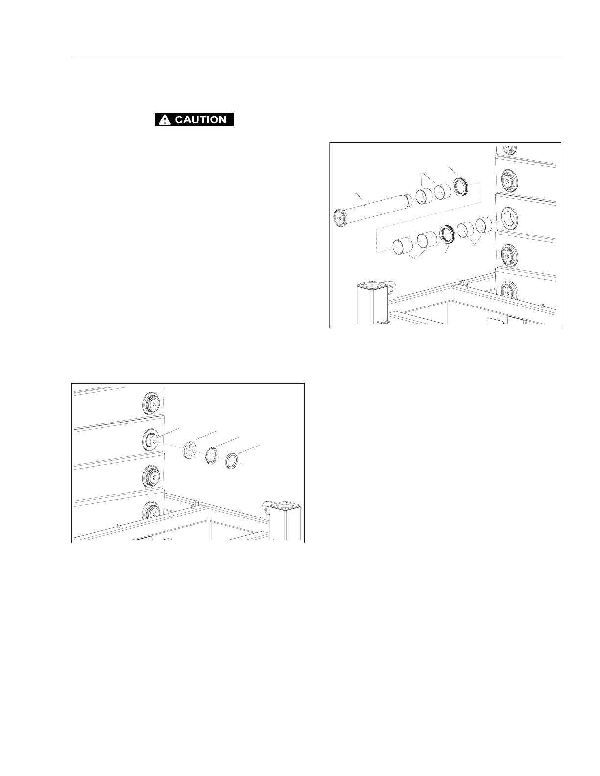
SECTION 3 - CHASSIS, PLATFORM & SCISSOR ARMS
Scissor Arms Disassembly
INDIVIDUAL SCISSOR ARMS ARE HEAVY. USE CAUTION WHEN
REMOVING. USE APPROPRIATE LIFTING DEVICES.
1. Disconnect battery and shutoff flow of hydraulic fluid
by closing the shutoff levers on the hydraulic tank
(see Figure 3-20.).
2. Remove Platform [see Figure 3-32., Platform
Removal - 1 of 2 (Front of Platform) and Figure 3-33.,
Platform Removal - 2 of 2 (Rear of Platform)].
3. Hydraulic lines and electrical lines run through the
insides of the scissor arms. These hoses and wires
must be removed before removing the arm components.
4. Brace the Scissor Arm Assembly as well as the individual Scissor Arm(s) being removed.
NOTE: The below steps apply to each scissor arm pin.
5. On the left side of the machine, remove the Nut (2)
with a spanner wrench. Next, remove the Retaining
Washer (3) and Washer and Pin (4).
1
4
3
2
6. Move to the right side of the machine. The Arm Pin
(1) can now be pulled out of the scissor arm stack.
Remove the four Bushings (2), two Ball Thrust Bearings (3), and two Bushings (4).
3
2
1
2
3
4
1. Arm Pin (75mm, 90mm, 100mm, or 120mm)
2. Bushing (75 x 60mm, 90 x 60mm, 100 x 60mm,
or 120 x 60mm)
3. Ball Thrust Bearing
4. Bushing (75 x 60mm, 75 x 80mm, 100 x 80mm,
90 x 90mm, or 120 x 100mm)
Figure 3-39. Scissor Arm Removal (Right Side)
7. Repeat steps 4 and 5 at each Arm Pin in order to
remove the individual scissor arm.
8. Carefully lift the arm from the assembly.
NOTE: Follow the removal steps in reverse order when
installing the scissor arms.
Tighten the Lock Nuts until there is zero clearance
1. Arm Pin (75mm, 90mm, 100mm, or 120mm)
2. Nut (M60, M80, M90, or 100mm)
3. Retaining Washer (MB18, MB20, 60mm, or 80mm)
4. Washer & Pin
Figure 3-38. Scissor Arm Removal (Left Side)
between the arms and the bearings. Back off one
quarter of a revolution. Bend the lip on the corresponding Retaining Washer into the notch on the
lock nuts.
3121322 – JLG Lift – 3-43
Page 76

SECTION 3 - CHASSIS, PLATFORM & SCISSOR ARMS
NOTES:
3-44 – JLG Lift – 3121322
Page 77

SECTION 4. HYDRAULICS
SECTION 4 - HYDRAULICS
4.1 CYLINDERS - THEORY OF OPERATION
Deck Extension Cylinder:
The deck is extended and retracted by means of a double
acting cylinder controlled by the first section in the main
control valve (see Figure 4-33., Main Valve Block). The
service line relief valve in the control valve is set at 1160
psi (80 bar) for extend and 3046 psi (210 bar) for retract.
Lift Cylinder:
The lift cylinder is a single acting cylinder incorporating
dual solenoid holding valves and a pilot operated check
valve for emergency lowering. The lifting function is con-
trolled by the 3
Figure 4-33.). Lift speed is limited by flow from section 1 in
the pump.
Lowering is operated by energising the two solenoid holding valves together with the 3rd section of the main control
valve (see Figure 4-33.). Descent speed is controlled by
an adjustable line mounted flow control valve.
To enable lowering at full speed when the engine is
stopped (i.e. there is no hydraulic power available to act
as a pilot supply for the electrical actuator), a pilot line can
be connected to the auxiliary port "M" on the control valve
via a check valve. This provides the hydraulic power necessary to shift the lower valve section.
rd
section of the main control valve (see
Outrigger Cylinders:
The automatic self leveling system is controlled by 4 double acting cylinders mounted at each corner of the
machine chassis. These cylinders incorporate pilot operated holding valves on the piston side. The cracking pressure for these valves is 15 psi (1 bar) for the rear and 116
psi (8 bar) for the front.
the opposite work port opening to reservoir. Once the circuit is deactivated (control returned to neutral), the valve
spool returns to neutral (center) and oil flow is then
directed through the valve body and returns to reservoir. A
typical control valve consists of the valve body, sliding
spool, and two solenoid assemblies. The spool is
machine fitted in the bore of the valve body. Lands on the
spool divide the bore into various chambers, which, when
the spool is shifted, align with corresponding ports in the
valve body open to common flow. At the same time other
ports would be blocked to flow. The spool is springloaded to center position, therefore when the control is
released, the spool automatically returns to neutral, prohibiting any flow through the circuit.
Relief Valves
Main relief valves are installed at various points within the
hydraulic system to protect associated systems and components against excessive pressure. Excessive pressure
can be developed when a cylinder reaches its limit of
travel and the flow of pressurized fluid continues from the
system control. The relief valve provides an alternate path
for the continuing flow from the pump, thus preventing
rupture of the cylinder, hydraulic line or fitting. Complete
failure of the system pump is also avoided by relieving circuit pressure. The relief valve is installed in the circuit
between the pump outlet (pressure line) and the cylinder
of the circuit, generally as an integral part of the system
valve bank. Relief pressures are set slightly higher than
the load requirement, with the valve diverting excess
pump delivery back to the reservoir when operating pressure of the component is reached.
Steer Cylinder:
Steering has a dedicated solenoid valve mounted in the
valve compartment. This valve receives hydraulic power
from the 3rd pump section and is protected by an inline filter. The steering valve incorporates a full flow pressure
relief valve which is set at 2538 psi (175 bar).
4.2 VALVES - THEORY OF OPERATION
Crossover Relief Valves
Crossover relief valves are used in circuits where the actuator requires an operating pressure lower than that supplied to the system. When the circuit is activated and the
required pressure at the actuator is developed, the crossover relief diverts excess pump flow to the reservoir. Individual, integral relief’s are provided for each side of the
circuit.
Solenoid Control Valves (Bang-Bang)
Control valves used are four-way three-position solenoid
valves of the sliding spool design. When a circuit is activated and the control valve solenoid energizes, the spool
is shifted and the corresponding work port opens to permit oil flow to the component in the selected circuit, with
3121322 – JLG Lift – 4-1
Proportional Valve
Flow is proportional to the amount of voltage supplied to
the valve coil. Voltage is gained by the machine controller
and determined by the position of the joystick.
Page 78

SECTION 4 - HYDRAULICS
4.3 CYLINDER CHECKING PROCEDURE
NOTE: Cylinder check must be performed anytime a system
component is replaced or when improper system
operation is suspected.
1. Using all applicable safety precautions, activate
engine and fully extend cylinder to be checked. Shut
down engine.
2. Carefully disconnect hydraulic hoses from retract
port of cylinder. There will be some initial weeping of
hydraulic fluid which can be caught in a suitable
container. After the initial discharge, there should be
no further drainage from the retract port.
3. Activate engine and extend cylinder.
4. If cylinder retract port leakage is less than 6-8 drops
per minute, carefully reconnect hose to port and
retract cylinder. If leakage continues at a rate of 6-8
drops per minute or more, cylinder repair must be
made.
5. With cylinder fully retracted, shut down engine and
carefully disconnect hydraulic hose from cylinder
extend port.
6. Activate engine and retract cylinder. Check extend
port for leakage.
7. If extend port leakage is less than 6-8 drops per
minute, carefully reconnect hose to extend port,
then activate cylinder through one complete cycle
and check for leaks. If leakage continues at a rate of
6-8 drops per minute or more, cylinder repairs must
be made.
4.4 CYLINDER REPAIR
NOTE: The following are general procedures that apply to
all of the cylinders on this machine. Procedures that
apply to a specific cylinder will be so noted. Refer to
Figure 4-24. thru Figure 4-27. for specific cylinder
assembly breakdowns and for specific parts references. Refer to JLG Parts Manual 3121323 for seal
kits and part numbers.
Disassembly
BEFORE REMOVING CYLINDERS FROM THE MACHINE BE SURE
TO SUPPORT THE MACHINE AND SCISSOR ARMS/PLATFORM
WITH SAFETY PROPS, FORKLIFTS, OR OVERHEAD CRANE TO
PREVENT RELEVANT COMPONENTS FROM COLLAPSING AND
CAUSING SERIOUS INJURY OR DEATH. (SEE FIGURE 4-28.)
1. Remove cylinder(s) from the machine by first disconnecting all hoses and/or wires and any valves.
Next, unscrew bolts connecting cylinder(s) to the
machine. If applicable, remove any pins connecting
the cylinders to the machine.
NOTE: Step 2 applies only to the Lift Cylinder.
2. To prevent damage, remove the hydraulic block,
load retaining valve block, and check valve block
from the lift cylinder barrel by unscrewing the 8 set
screws.
Cylinder
Barrel
Valve
Blocks
Setscrews
Figure 4-1. Lift Cylinder Valve Block Removal
4-2 – JLG Lift – 3121322
Page 79

SECTION 4 - HYDRAULICS
NOTE: Step 3 applies only to the Outrigger Cylinders.
3. To prevent damage, remove the safety valve and
limit switch from the top of the outrigger cylinders.
Limit Switch
Safety Valve
Outrigger
Cylinder
Figure 4-2. Safety Valve and Limit Switch Removal
7. Place the cylinder barrel into a suitable holding fixture.
Figure 4-3. Cylinder Barrel Support
8. Using a spanner wrench, loosen and remove the
cylinder head from the barrel.
Cylinder
Rod
NOTICE
DISASSEMBLY OF THE CYLINDER SHOULD BE PERFORMED ON
A CLEAN WORK SURFACE IN A DIRT FREE WORK AREA.
4. Connect a suitable auxiliary hydraulic power source
to the cylinder port block fitting.
DO NOT FULLY EXTEND CYLINDER TO THE END OF STROKE.
RETRACT CYLINDER SLIGHTLY TO AVOID TRAPPING PRESSURE.
5. Operate the hydraulic power source and extend the
cylinder. Shut down and disconnect the power
source.
6. Adequately support the cylinder rod, if applicable.
Cylinder
Head
Barrel
Figure 4-4. Cylinder Head Removal
NOTICE
EXTREME CARE SHOULD BE TAKEN WHEN REMOVING THE CYLINDER ROD, HEAD, AND PISTON. AVOID PULLING THE ROD OFFCENTER, WHICH COULD CAUSE DAMAGE TO THE PISTON AND
CYLINDER BARREL SURFACES.
3121322 – JLG Lift – 4-3
Page 80

SECTION 4 - HYDRAULICS
9. With the barrel clamped securely, apply pressure to
the rod pulling device and carefully withdraw the
complete rod assembly from the cylinder barrel.
.
Figure 4-5. Cylinder Rod Support
10. Using suitable protection, clamp the cylinder rod in
a vise or similar holding fixture as close to the piston
as possible.
11. Loosen and remove the setscrew which attaches the
piston to the rod, and remove the piston.
12. Unscrew the piston counter-clock-wise, by hand,
and remove the piston from the cylinder rod.
Piston
Cylinder
Rod
Figure 4-7. Piston Removal
13. Remove and discard the piston o-rings, seal rings,
and, if applicable, the snap ring.
Snap Ring
(Outrigger Cylinder
Only)
O-Ring
Pistons
Setscrews
Figure 4-6. Piston Setscrew Removal
Piston
Piston
Seal
Figure 4-8. Piston Seals
4-4 – JLG Lift – 3121322
Page 81

SECTION 4 - HYDRAULICS
14. If applicable, remove the spacer from the rod.
Spacer
Cylinder
Rod
Figure 4-9. Spacer Removal
15. Remove the rod from the holding fixture.
16. Remove the cylinder head from the cylinder rod.
Cylinder
Head
17. If applicable, remove and discard the cylinder head
seal, rod seal, wiper, o-ring(s), back-up ring, and
snap ring.
Snap Ring
(Outrigger Cylinder Only)
Backup Ring
(Outrigger Cylinder Only)
Wiper
Head
Seal
O-Ring
Rod
Seal
Cylinder
Head
O-Ring
Figure 4-11. Cylinder Head Seals
Cleaning and Inspection
1. Clean all parts thoroughly in an approved cleaning
solvent.
2. Inspect the cylinder rod for scoring, tapering, ovality,
or other damage. If necessary, dress rod with
Scotch Brite or equivalent. Replace rod if necessary.
Cylinder
Rod
Figure 4-10. Cylinder Head Removal
3. Inspect threaded portion of rod for excessive damage. Dress threads as necessary.
4. Inspect inner surface of cylinder barrel tube for scoring or other damage. Check inside diameter for
tapering or ovality. Replace if necessary.
5. Inspect threaded portion of barrel for damage. Dress
threads as necessary.
6. Inspect piston surface for damage and scoring and
for distortion. Dress piston surface or replace piston
as necessary.
7. If applicable, inspect threaded portion of piston for
damage. Dress threads as necessary.
8. Inspect seal and o-ring grooves in piston for burrs
and sharp edges. Dress applicable surfaces as necessary.
9. Inspect cylinder head inside diameter for scoring or
other damage and for ovality and tapering. Replace
as necessary.
10. Inspect threaded portion of head for damage. Dress
threads as necessary.
3121322 – JLG Lift – 4-5
Page 82

SECTION 4 - HYDRAULICS
11. Inspect seal and o-ring grooves in head for burrs
and sharp edges. Dress applicable surfaces as necessary.
12. Inspect cylinder head outside diameter for scoring
or other damage and ovality and tapering. Replace
as necessary.
13. If applicable, inspect rod and barrel bushings for
signs of excessive wear or damage. Replace as necessary.
a. Thoroughly clean bushing housing of burrs, dirt,
etc. to facilitate bearing installation.
b. Inspect bushing housing for wear or other dam-
age. If the bushing housing is worn or damaged,
rod/barrel must be replaced.
c. Lubricate inside of bushing housing with WD40
prior to bushing installation.
d. Using an arbor of the correct size, carefully
press the bushing(s) into bushing housing on
the cylinder rod and cylinder barrel, if applicable.
Bushing
Housing
Bushing
Assembly
NOTE: Prior to cylinder assembly, ensure that the proper
cylinder seal kit is used. See your JLG Parts Manual
3121323. Always replace seals when servicing cylinders.
Apply a light film of hydraulic oil to all components prior to
assembly.
1. A special tool is used to install a new rod seal into
the applicable cylinder head gland groove.
ROD
SEAL
Figure 4-13. Rod Seal Installation
Arbor
To ol
Figure 4-12. Bushing Installation
NOTE: Step 14 applies only to the Lift Cylinder.
14. Inspect the hydraulic block, load retaining valve
block, and check valve block for any damage.
Replace as necessary.
15. Inspect the oil ports for blockage or the presence of
dirt or other foreign material. Repair as necessary.
NOTICE
WHEN INSTALLING PISTON SEALS, ENSURE SEALS ARE
INSTALLED PROPERLY. IMPROPER SEAL INSTALLATION COULD
RESULT IN CYLINDER LEAKAGE AND IMPROPER CYLINDER
OPERATION.
WHEN INSTALLING THE WIPER SEAL, APPLY LOCTITE #609 ON
THE WIPER SEAL IN THREE EVENLY SPACED PLACES TO AID IN
RETENTION OF THE SEAL.
2. Use a soft mallet to tap a new wiper seal into the
applicable cylinder head gland groove. Install a new
rod seal into the applicable cylinder head glandgroove.
16. If applicable, inspect piston rings for cracks or other
damage. Replace as necessary.
4-6 – JLG Lift – 3121322
Page 83

SECTION 4 - HYDRAULICS
3. Install a new head seal, new o-rings, and, if applicable, a new backup ring, in the appropriate outside
diameter groove of the cylinder head.
Snap Ring
(Outrigger Cylinder Only)
Backup Ring
(Outrigger Cylinder Only)
Wiper
Head
Seal
O-Ring
Rod
Seal
Cylinder
Head
O-Ring
Figure 4-14. Cylinder Head Seal Installation
4. Carefully install the cylinder head on the rod, ensuring that the wiper, o-ring, and rod seals are not damaged or dislodged. Push the head along the rod to
the rod end, as applicable.
5. Carefully slide the piston spacer onto the cylinderrod.
Spacer
Cylinder
Rod
Figure 4-16. Spacer Installation
6. If applicable, correctly install new o-ring and snap
ring in the inner piston diameter groove.
Cylinder
Head
Cylinder
Rod
Figure 4-15. Cylinder Head Installation
7. If applicable, correctly place new seals in the outer
piston diameter groove(s). (A tube, with I.D. slightly
larger than the O.D. of the piston is recommended to
install the solid seal.)
Snap Ring
(Outrigger Cylinder
O-Ring
Only)
Piston
Piston
Seal
Figure 4-17. Piston Seal Installation
8. Using suitable protection, clamp the cylinder rod in
a vise or similar holding fixture as close to piston as
possible.
3121322 – JLG Lift – 4-7
Page 84

SECTION 4 - HYDRAULICS
9. Carefully thread the piston clock-wise on the cylinder rod hand tight until it abuts the spacer, ensuring
that the o-ring, snap ring, and piston seals are not
damaged or dislodged.
Piston
Spacer
Cylinder
Rod
Figure 4-18. Piston Installation
NOTICE
EXTREME CARE SHOULD BE TAKEN WHEN INSTALLING THE
CYLINDER ROD, HEAD, AND PISTON. AVOID PULLING THE ROD
OFF-CENTER, WHICH COULD CAUSE DAMAGE TO THE PISTON
AND CYLINDER BARREL SURFACES.
13. With barrel clamped securely, and while adequately
supporting the rod, insert the piston end into the
barrel cylinder. Ensure that the piston loading o-ring
and seal ring are not damaged or dislodged.
Cylinder
Head
Cylinder
Rod
10. Insert the setscrews on the piston and tighten to
lock piston in place on cylinder rod.
Pistons
Setscrews
Figure 4-19. Piston Setscrew Installation
11. Remove the cylinder rod from the holding fixture.
12. Position the cylinder barrel in a suitable holding fixture.
Piston
Cylinder
Barrel
Figure 4-20. Rod Installation
14. Continue pushing the rod into the barrel until the cylinder head can be inserted into the barrel cylinder.
4-8 – JLG Lift – 3121322
Page 85

Cylinder
Rod
SECTION 4 - HYDRAULICS
Limit Switch
Safety Valve
Cylinder
Head
Barrel
Figure 4-21. Rod Assembly Installation
15. Use a spanner wrench to tighten the cylinder head
on the barrel.
16. If applicable, after the cylinder has been reassembled, the rod should be pushed all the way in (fully
retracted) prior to the reinstallation of any valve
block or load check valve.
Cylinder
Barrel
Valve
Blocks
Outrigger
Cylinder
NOTE: Outrigger Cylinders only.
Figure 4-23. Safety Valve and Limit Switch Installation
NOTE: Refer to Figure 1-3., Torque Chart - (In/Lb - Ft/Lb).
(For ASTM Fasteners) to Figure 1-5., Torque Chart (Nm) - (For Metric Class Fasteners). for setscrew
torques.
Setscrews
NOTE: Lift Cylinder only.
Figure 4-22. Valve Block Installation
3121322 – JLG Lift – 4-9
Page 86

SECTION 4 - HYDRAULICS
22
10
9
8
11
6
2
7
1
3
4
1. Barrel Weldment
2. Rod Weldment
3. Piston
4. Cylinder Head
5. Wear Ring
6. Piston Seal
5
13
7. O-Ring
8. Cylinder Head
9. Wiper Ring
10. Rod Seal
11. O-Ring
12. Valve Cartridge
Figure 4-24. Lifting Cylinder Assembly
13. Test Fitting
14. Holding Valve Assembly
15. Capscrew, M6 x 50mm
16. Capscrew, M8 x 45mm
17. Check Valve Assembly
18. Valve Cartridge
12
21
14
19
20
15
16
12
17
18
21
19. O-Ring
20. O-Ring
21. Bushing
22. Bushing
4-10 – JLG Lift – 3121322
Page 87

SECTION 4 - HYDRAULICS
11
7
8
12
1
1. Barrel Weldment
2. Piston
3. Setscrew
4. Piston Seal
6
9
10
5
3
5. Spacer
6. Cylinder Head
7. Wiper
8. Rod Seal
9. O-Ring
10. Head Seal
11. Rod
12. Bushing
12
2
4
Figure 4-25. Steering Cylinder Assembly
Table 4-1. Steering Cylinder Specs
Maximum Working Pressure
Piston Head Torque (apply Loctite 242 prior to tightening)
Max Speed
Max Operating Temperature
3046 psi
(210 bar)
191.8 lb ft
(260Nm)
1.6 ft/sec
(0.5 m/sec)
- 4° F to 1 7 6° F
(-20°C to 80°C)
3121322 – JLG Lift – 4-11
Page 88

SECTION 4 - HYDRAULICS
3
17
5
8
4
13
14
15
16
7
12
11
10
9
1. Barrel
2. Mounting Flange
6
1
2
3. O-Ring
4. Piston
5. Setscrew
6. Piston Seal
7. Spacer
8. O-Ring
9. Cylinder Head
10. O-Ring
11. Backup Ring
12. Head Seal
13. Rod Seal
14. Wiper
15. Snap Ring
16. O-Ring
17. Rod
Figure 4-26. Leveling Cylinder Assembly
Table 4-2. Leveling Cylinder Specs
Max Working Pressure
Piston Head Torque (Apply Loctite 243 prior to tightening)(torque with Rod End)
Setscrew Torque (Apply Loctite 222 prior to tightening)
Max Speed
Max Operating Temperature
2683.1 psi
(185 bar)
442.5 lb ft
(600 Nm)
14.8 lb ft
(20 Nm)
1.6 ft/sec
(0.5 m/sec)
-22°F to 212°F
(-30°C to 100°C)
4-12 – JLG Lift – 3121322
Page 89

SECTION 4 - HYDRAULICS
11
12
1
9
6
8
3
10
1. Barrel
2. Piston
3. Setscrew
4. Piston Seal
5. Spacer
7
5
2
6. Cylinder Head
7. O-Ring
8. Head Seal
9. Wiper
10. Rod Seal
11. O-Ring
12. Rod
4
Figure 4-27. Extension Cylinder Assembly
Table 4-3. Extension Cylinder Specs
Max Working Pressure
Bore Relief Pressure
Piston Torque (Apply Loctite 242 prior to tightening)
Set screw Torque (Apply Loctite 222 prior to tightening)
Max Speed
Max Operating Temperature
3121322 – JLG Lift – 4-13
3046 psi
(210 bar)
1160 psi
(80 bar)
147.5 lb ft
(200 Nm)
14.8 lb ft
(20 Nm)
1.6 ft/sec
(0.5 m/sec)
-22°F to 176°F
(-30°C to 80°C)
Page 90

SECTION 4 - HYDRAULICS
Y
REMOVE ANY LOAD FROM PLATFORM. NEVER
WORK UNDER AN ELEVATED PLATFORM UNTIL IT
HAS BEEN RESTRAINED FROM MOVEMENT WITH
SAFETY PROPS, BLOCKING OR OVERHEAD SLING.
STRAP
STRAP
ARM SAFET
PROP
Figure 4-28. Arms and Platform Positioning and Support
4-14 – JLG Lift – 3121322
Page 91

4.5 VALVES
Valve Compartment
SECTION 4 - HYDRAULICS
1. Pressure Switch, Drive Enable & Brake Valve
2. Main Valve Block
Pressure Switch, Drive Enable
3. Steering Valve
4. Drive Valve
Figure 4-29. Valve/Hydraulic Compartment
• Operate the lower function to retract the
jacks and adjust the switch (screw on the
top of the switch) to trip at 2683 psi
(185 bar)
5. Hand Pump
6. Pressure Manifold
Figure 4-30. Pressure Switch Adjustment
3121322 – JLG Lift – 4-15
Page 92

SECTION 4 - HYDRAULICS
Brake Valve
2
Brake Valve Adjustment:
1
1. Torque to 5 ft lbs (6.8 Nm)
VALVE SCHEMATIC
A
P
T
Figure 4-31. Brake Valve
2. Torque to 20 ft lbs (27.1 Nm)
• Operating Pressure: 3000 psi (207 bar)
• Voltage: 24VDC
Figure 4-32. Brake Valve Adjustment
• To achieve smooth deceleration
when the joystick is returned quickly
from the max forward or backward
position to the neutral position, completely close the valve knob (shown
to the left) then open the knob 1/2 of
a revolution.
4-16 – JLG Lift – 3121322
Page 93

Main Valve Block
C
SECTION 4 - HYDRAULICS
1. Main Pressure Block
2. Platform
3. Drive 1
4. Lifting
5. Leveling Rear Left
6. Leveling Rear Right
7. Leveling Front Left
8
8. Leveling Front Right
7
6
5
4
3
1
2
LS
VALVE SCHEMATI
B
A
80
M
185
T
P
210
210
PLATFORM
BAB
A
210
DRIVE 1
Figure 4-33. Main Valve Block
LIFTING
210
A
LEVELING
B
210
REAR LEFT
AB
210
210
LEVELING
REAR RIGHT
210
BA
A
210
210
LEVELING
FRONT LEFT
B
210
LEVELING
FRONT RIGHT
3121322 – JLG Lift – 4-17
Page 94

SECTION 4 - HYDRAULICS
V
Adjust main pressure on top of the Main Pressure Block
• remove the cap and attach a pressure gauge to pressure test port (see Figure 4-35.)
• remove rubber plug from adjustment port
• adjust to 3045.8 psi (210 bar)(see Figure 4-35.)
Figure 4-34. Pressure Test Port
Steering Valve
A
Figure 4-35. Main Valve Pressure Adjustment
ALVE SCHEMATIC
A
B
T
P
B
PT
Figure 4-36. Steering Valve
Pressure Adjustment:
• remove the cap and attach a pressure gauge to pressure test port (see Figure 4-34.)
• operate the Steer Cylinder to end of stroke
• pressure can be set/adjusted by adjusting the screw in
the port
• set pressure to 2538 psi (175 bar)
4-18 – JLG Lift – 3121322
Page 95

Steer Valve Pressure Adjustment:
SECTION 4 - HYDRAULICS
Figure 4-37. Steer Valve Pressure Adjustment
• remove the cap and attach a pressure gauge to pressure test port (see Figure 4-34.)
• remove the black cover (shown in top picture) to gain
access to the adjustment screw (shown in bottom picture)
• operate the Steer Cylinder to end of stroke
• pressure can be set/adjusted by adjusting the screw in
the port
• set pressure to 2538 psi (175 bar)
3121322 – JLG Lift – 4-19
Page 96

SECTION 4 - HYDRAULICS
T
Drive Valve
A1 B1
VALVE SCHEMATIC
A2
B
A
T
P
B2
A3
B3
A4
B4
A
Figure 4-38. Drive Valve
4-20 – JLG Lift – 3121322
B
Page 97

Hand Pump
SECTION 4 - HYDRAULICS
16
Pump
Assembly
7
1
2
9
15
14
17
9
12
29
31
8
3
13
17
12
4
32
33
34
27
35
28
30
11
20
19
Valve
Assembly
6
10
11
20
19
23
20
24
11
10
11
5
36
27
19
37
20
20
26
21
20
21
20
25
Pump Assembly
1. Valve, Suction
2. Plug
3. Plug
4. Body
5. Rod, connecting
6. Lever
7. Piston
8. Seal
9. Seal
10. Pin
11. Ring, Retaining
12. Ball
13. Ring
14. Washer
15. RIng, Internal Retaining
16. Seal
17. Spring
Valve Assembly
18. Body
19. Ball
20. Ring
21. Bolt, M8 x 8mm
22. Spinner (Not Shown)
23. Spring
24. Plug
25. Screw
26. Fitting, Straight
28. Spring
29. Nut, M10
30. Seal
31. Setscrew
32. Relief, Valve
33. Pin, Ball Driving
34. Plate, Seal
35. Valve Body
36. Knob Assembly
37. Valve Body
27. Seal
Figure 4-39. Hand Pump Assembly
3121322 – JLG Lift – 4-21
Page 98

SECTION 4 - HYDRAULICS
VALVE SCHEMATIC
B
S
Figure 4-40. Hand Pump Schematic
Lift/Lower Valve Block
Lift/Lower
Valve Block
1
Diagnostic
Te s t Por t
Lift Cylinder
Solenoid
2
Valves
Figure 4-41. Lift/Lower Valve Block
Solenoid Valves (Qty. 2)
1. Torque to 5 ft lbs (6.8 Nm)
2. Torque to 20 ft lbs (27.1 Nm)
• Operating Pressure: 5000 psi (345 bar)
Diagnostic Test Port
• Pressure Rating: 9137 psi (630 bar)
4-22 – JLG Lift – 3121322
Page 99

Platform Lower Flow Valve
SECTION 4 - HYDRAULICS
• with the rated load on the platform
(see Table 1-1), adjust the knob
shown to the left to obtain the lowering speed as specified in (Table 1-1)
Figure 4-42. Platform Lower Flow Valve
Outrigger Safety Valves
Outrigger
Cylinder
Safety Valve
Front Outriggers:
• Operating Pressure: 116 psi (8 bar)
Rear Outriggers:
• Operating Pressure: 14.5 psi (1 bar)
Figure 4-43. Outrigger Valves
3121322 – JLG Lift – 4-23
Page 100

SECTION 4 - HYDRAULICS
NOTES:
4-24 – JLG Lift – 3121322
 Loading...