

Page 1
Page 2

Page 3
3121299 660SJ/600S 3
Page 4

Page 5

TABLE OF CONTENTS
SECTION 1 - FRAME ........................................................................................................................................................................... 7
FIGURE 1-1. AXLE INSTALLATION ................................................................................................................................................ 8
FIGURE 1-2. STEERING INSTALLATION WITHOUT TOW PACKAGE ........................................................................................ 10
FIGURE 1-3. STEERING INSTALLATION WITH TOW PACKAGE................................................................................................ 14
FIGURE 1-4. TIRE AND WHEEL DRIVE INSTALLATIONS ........................................................................................................... 18
FIGURE 1-5. DRIVE HUB ASSEMBLY .......................................................................................................................................... 22
FIGURE 1-6. DRIVE MOTOR ASSEMBLY .................................................................................................................................... 26
FIGURE 1-7. DRIVE VALVES AND SHIELDS INSTALLATION (FRAME MOUNTED) .................................................................. 28
FIGURE 1-8. TOW PACKAGE INSTALLATION (OPTIONAL) ....................................................................................................... 32
SECTION 2 - TURNTABLE ................................................................................................................................................................ 35
FIGURE 2-1. CONTROL VALVES INSTALLATIONS ..................................................................................................................... 36
FIGURE 2-2. CONTROL VALVES INSTALLATIONS ..................................................................................................................... 40
FIGURE 2-3. MAIN CONTROL VALVE ASSEMBLY ...................................................................................................................... 42
FIGURE 2-4. MAIN CONTROL VALVE ASSEMBLY ...................................................................................................................... 46
FIGURE 2-5. ACCESSORY VALVE ASSEMBLY ........................................................................................................................... 50
FIGURE 2-6. SWING DRIVE, TURNTABLE BEARING AND LOCK INSTALLATIONS .................................................................. 52
FIGURE 2-7. SWING MOTOR/HUB ASSEMBLY ........................................................................................................................... 54
FIGURE 2-8. DEUTZ D2011 ENGINE INSTALLATION ................................................................................................................. 58
FIGURE 2-9. DEUTZ TD2.9L4 ENGINE INSTALLATION .............................................................................................................. 68
FIGURE 2-10. GM ENGINE INSTALLATION ................................................................................................................................. 80
FIGURE 2-11. PISTON PUMP ASSEMBLY ................................................................................................................................... 86
FIGURE 2-12. GEAR PUMP ASSEMBLY ...................................................................................................................................... 92
FIGURE 2-13. TANK INSTALLATIONS .......................................................................................................................................... 94
FIGURE 2-14. ROTARY COUPLING INSTALLATION ................................................................................................................... 98
FIGURE 2-15. GROUND CONTROL BOX ASSEMBLY (FIBERGLASS BOX) ............................................................................ 102
FIGURE 2-16. GROUND CONTROL BOX ASSEMBLY (STEEL BOX) ........................................................................................ 106
FIGURE 2-17. ELECTRICAL OPTIONS INSTALLATION (TURNTABLE MOUNTED) ................................................................. 110
FIGURE 2-18. ENGINE TRAY JACK INSTALLATION (OPTIONAL) ............................................................................................ 114
FIGURE 2-19. HOODS (ABS) AND LIFTING PLATE INSTALLATIONS ...................................................................................... 116
FIGURE 2-20. HOODS (STEEL) AND LIFTING PLATE INSTALLATIONS (DEUTZ D2011 AND GM ENGINES) ....................... 122
FIGURE 2-21. HOODS (STEEL) AND LIFTING PLATE INSTALLATIONS (DEUTZ TD2.9L4 ENGINES) ................................... 128
FIGURE 2-22. 7500W SKYPOWER GENERATOR INSTALLATION - DEUTZ ENGINE (OPTIONAL) ........................................ 134
FIGURE 2-23. 7500W SKYPOWER GENERATOR INSTALLATION - GM ENGINE (OPTIONAL) .............................................. 140
SECTION 3 - BOOM ........................................................................................................................................................................ 145
FIGURE 3-1. BOOM INSTALLATION - 600S ............................................................................................................................... 146
FIGURE 3-2. BOOM INSTALLATION - 660SJ ............................................................................................................................. 150
FIGURE 3-3. MAIN BOOM ASSEMBLIES ................................................................................................................................... 156
FIGURE 3-4. ROTATOR ASSEMBLIES ....................................................................................................................................... 160
FIGURE 3-5. CONTROL VALVE INSTALLATION (BOOM) ......................................................................................................... 162
FIGURE 3-6. POWER TRACK INSTALLATIONS......................................................................................................................... 166
SECTION 4 - PLATFORM ................................................................................................................................................................ 169
FIGURE 4-1. PLATFORM COMPONENTS INSTALLATION ....................................................................................................... 170
FIGURE 4-2. PLATFORM COMPONENTS INSTALLATION (FALL ARREST PLATFORM) ........................................................ 174
FIGURE 4-3. PLATFORM CONSOLE ASSEMBLY ...................................................................................................................... 176
FIGURE 4-4. CONTROLLER ASSEMBLY (LIFT AND SWING) ................................................................................................... 180
FIGURE 4-5. CONTROLLER ASSEMBLY (DRIVE AND STEER)................................................................................................ 182
FIGURE 4-6. SOFT TOUCH SYSTEM INSTALLATION (OPTIONAL) ......................................................................................... 184
SECTION 5 - CYLINDER ................................................................................................................................................................. 187
FIGURE 5-1. AXLE LOCKOUT CYLINDER ASSEMBLY ............................................................................................................. 188
FIGURE 5-2. PLATFORM LEVEL SLAVE CYLINDER ASSEMBLY ............................................................................................. 190
FIGURE 5-3. MAIN LIFT CYLINDER ASSEMBLY ....................................................................................................................... 194
FIGURE 5-4. JIB LIFT CYLINDER ASSEMBLY - 660SJ .............................................................................................................. 196
FIGURE 5-5. MASTER CYLINDER ASSEMBLY .......................................................................................................................... 198
FIGURE 5-6. STEER CYLINDER ASSEMBLY ............................................................................................................................. 200
FIGURE 5-7. TELESCOPE CYLINDER ASSEMBLY ................................................................................................................... 202
SECTION 6 - HYDRAULIC .............................................................................................................................................................. 205
3121299 660SJ/600S 5
Page 6

TABLE OF CONTENTS
FIGURE 6-1. HYDRAULIC DIAGRAM - AXLE LOCKOUT ............................................................................................................ 206
FIGURE 6-2. HYDRAULIC DIAGRAM - DRIVE AND STEER (2WD/2WS) ................................................................................... 208
FIGURE 6-3. HYDRAULIC DIAGRAM - DRIVE AND STEER (4WD/2WS) ................................................................................... 210
FIGURE 6-4. HYDRAULIC DIAGRAM - STANDARD ................................................................................................................... 212
FIGURE 6-5. HYDRAULIC DIAGRAM - STANDARD ................................................................................................................... 216
FIGURE 6-6. HYDRAULIC DIAGRAM LIST .................................................................................................................................. 220
SECTION 7 - ELECTRICAL .............................................................................................................................................................. 221
FIGURE 7-1. ELECTRICAL DIAGRAM LIST ................................................................................................................................ 222
FIGURE 7-2. HARNESS COMPONENTS INSTALLATION .......................................................................................................... 224
FIGURE 7-3. HARNESS COMPONENTS INSTALLATION .......................................................................................................... 242
SECTION 8 - DECALS ..................................................................................................................................................................... 261
FIGURE 8-1. DECAL INSTALLATION (ANSI SPEC) .................................................................................................................... 262
FIGURE 8-2. DECAL INSTALLATION (COUNTRY SPEC) .......................................................................................................... 266
FIGURE 8-3. DECAL INSTALLATION (AUSTRALIAN AND CE SPEC) ....................................................................................... 272
SECTION 9 - RECOMMENDED SERVICE PARTS STOCK ............................................................................................................ 275
FIGURE 9-1. MODEL 600SJ/660SJ STANDARD PARTS ............................................................................................................ 276
FIGURE 9-2. MODEL 600SJ/660SJ VARIABLE PARTS .............................................................................................................. 278
SECTION 10 - SPECIAL OPTIONS ................................................................................................................................................. 279
FIGURE 10-1. SPECIAL OPTIONS .............................................................................................................................................. 280
PART NUMBER INDEX .................................................................................................................................................................... 287
6 660SJ/600S 3121299
Page 7

SECTION 1 - FRAME
SECTION 1 - FRAME
3121299 660SJ/600S 7
Page 8
SECTION 1 - FRAME
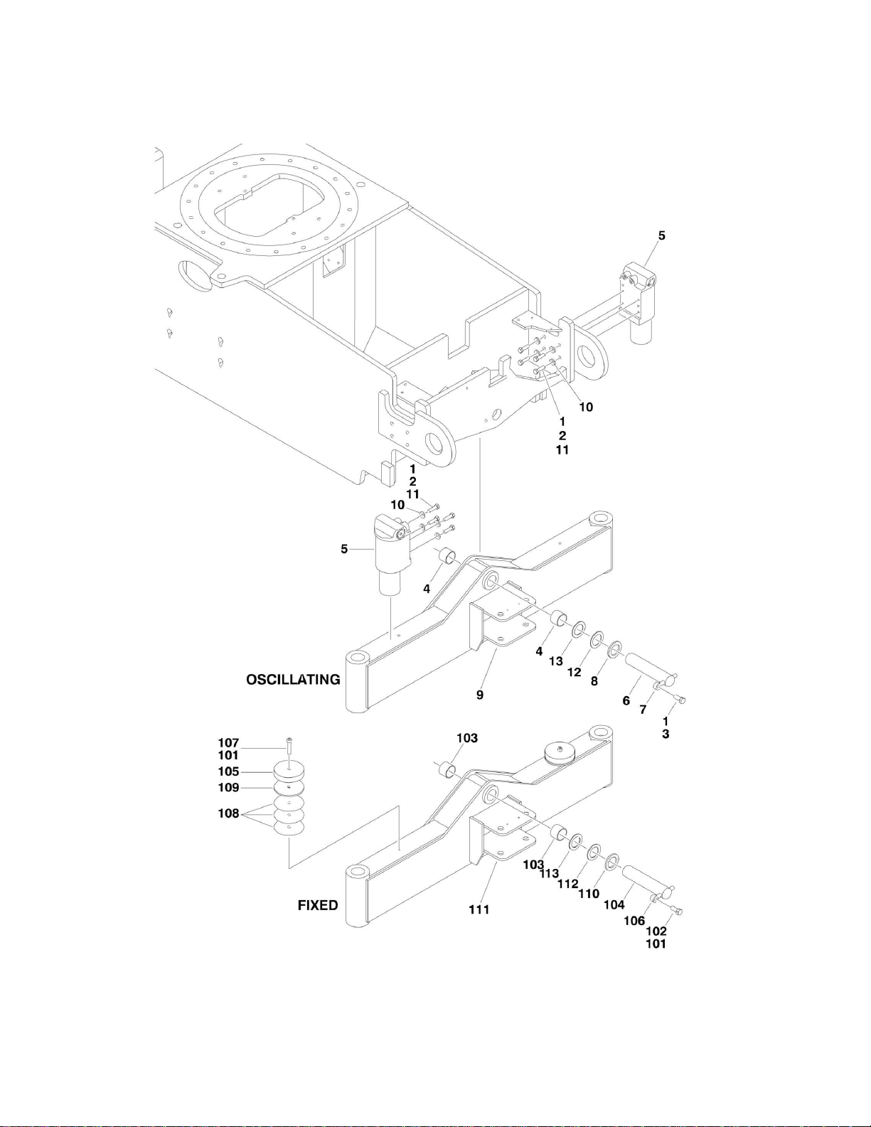
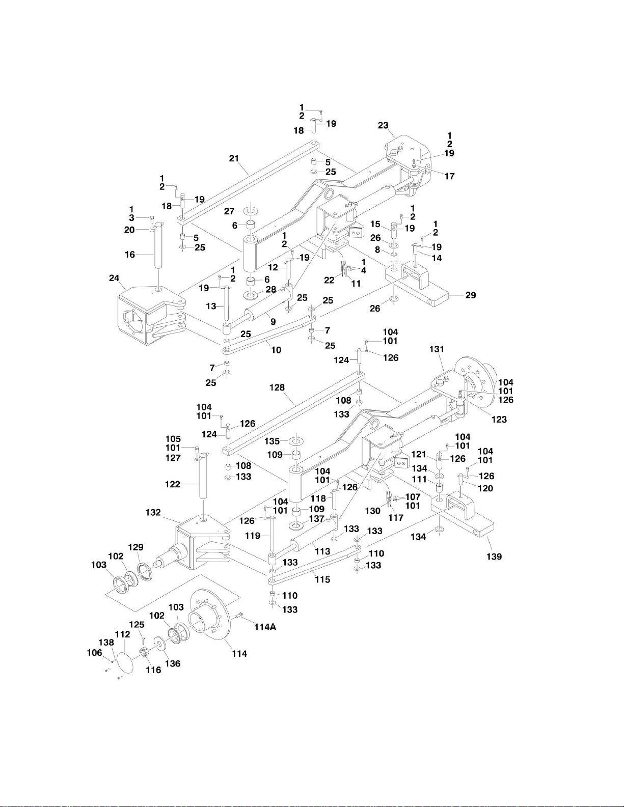
FIGURE 1-1. AXLE INSTALLATION
8 660SJ/600S 3121299
Page 9

FIGURE 1-1. AXLE INSTALLATION
ITEM
PART NUMBER
QTY
DESCRIPTION
REV
Ref
AXLE INSTALLATIONS - OSCILLATING
1001148168
Ref
Axle without Tow Package
C 1001148170
Ref
Axle with Tow Package
C 1 0100011
AR
Compound, Locking
2 0641814
8
Bolt 1/2in-13NC x 1-3/4in
3 0642012
1
Bolt 5/8in-11NC x 1-1/2in
4 0961950
2
Bearing
5
1684465
2
Lockout Cylinder Assembly (See CYLINDER SECTION for
Breakdown)
6
3423184
1
Pin 7
3841258
1
Keeper, Pin
8 4740158
AR
Thrustwasher (1/4in Thick)
9 Ref
Axle Weldment Options:
9 1001148171
1
Axle without Tow Package
9 1001148172
1
Axle with Tow Package (Not Shown)
10
4891800
8
Flatwasher 1/2in Hardened
11
0100038
AR
Primer, Locking
12
4740229
AR
Thrustwasher (1/8in Thick)
13
4071101
AR
Shim (18Ga)
1001148169
Ref
AXLE INSTALLATIONS - FIXED
C
101
0100011
AR
Compound, Locking
102
0642012
1
Bolt 5/8in-11NC x 1-1/2in
103
0961950
2
Bearing
104
3423184
1
Pin, Pivot
105
3539877
2
Plate, Stop
106
3841258
1
Keeper, Pin
107
3931840
2
Screw 1/2in-13NC x 2-1/2in
108
4070944
6
Shim (.06)
109
4070945
2
Shim (.25)
110
4740158
AR
Thrustwasher
111
1001148171
1
Axle Weldment
112
4071101
AR
Shim (18Ga)
113
4740229
AR
Thrustwasher (1/8in Thick)
SECTION 1 - FRAME
3121299 660SJ/600S 9
Page 10
SECTION 1 - FRAME
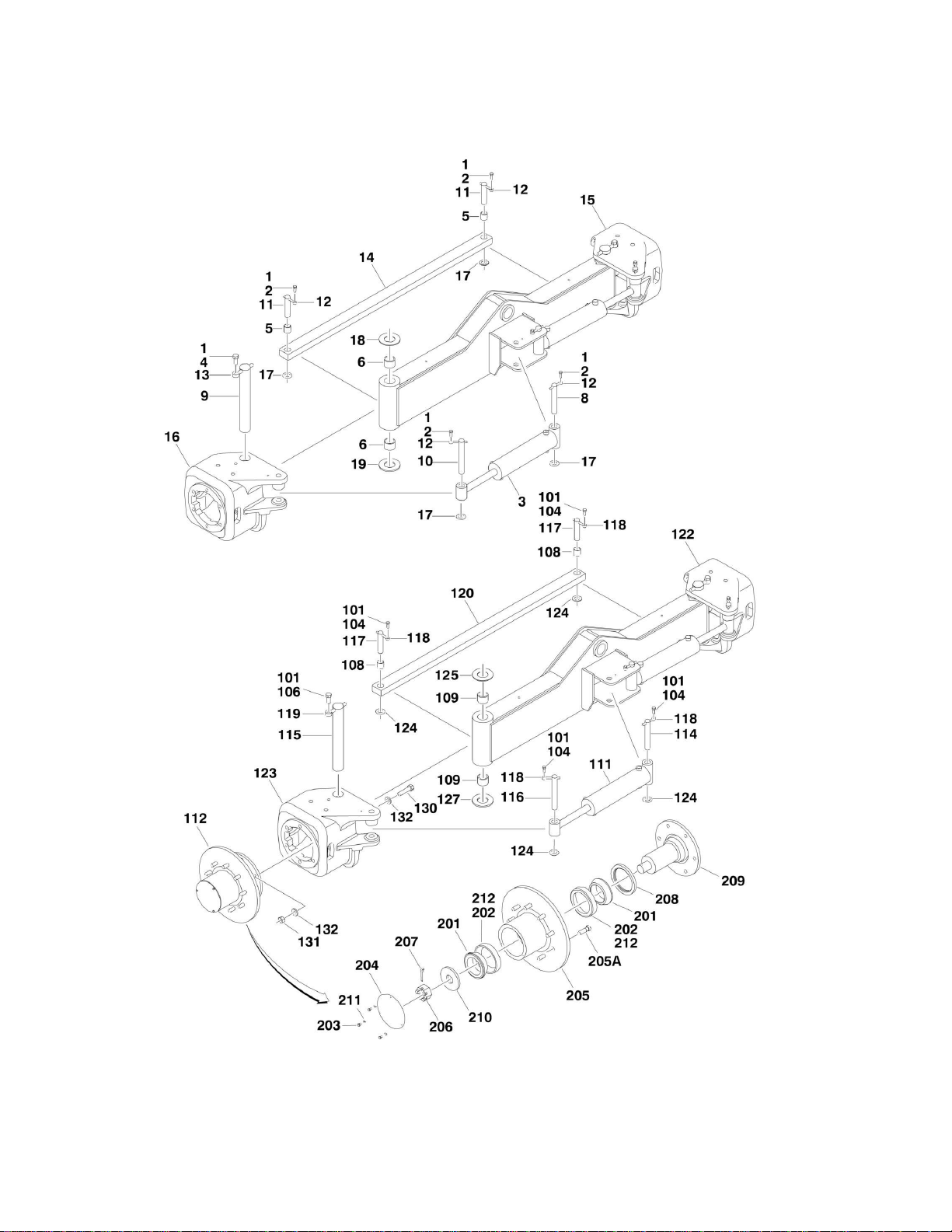
FIGURE 1-2. STEERING INSTALLATION WITHOUT TOW PACKAGE
10 660SJ/600S 3121299
Page 11

SECTION 1 - FRAME
ITEM
PART NUMBER
QTY
DESCRIPTION
REV
Ref
4WD STEERING INSTALLATION
1001148162
Ref
4WD/2WS
C 1001148163
Ref
4WD/4WS (Note: Double qty for 4WD/4WS Machines)
B 1 0100011
AR
Compound, Locking
2 0641608
6
Bolt 3/8in-16NC x 1in
3
1001097242
2
Steer Cylinder Assembly (See CYLINDER SECTION for
Breakdown)
4
0642012
2
Bolt 5/8in-11NC x 1-1/2in
5 0962356
2
Bushing
6 0962131
4
Bushing
8 3422326
2
Pin 9
3422900
2
Kingpin
10
3422902
2
Pin 11
3422903
2
Pin 12
3841143
6
Keeper, Pin
13
3841258
2
Keeper, Pin
14
1001155574
1
Tie-Rod
15
1001099387
1
Spindle - Left Side
16
1001099196
1
Spindle - Right Side
17
4740111
6
Thrustwasher
18
4740256
2
Thrustwasher
19
4740463
2
Thrustwasher
1001148161
Ref
2WD STEERING INSTALLATION
C
101
0100011
AR
Compound, Locking
104
0641608
6
Bolt 3/8in-16NC x 1in
106
0642012
2
Bolt 5/8in-11NC x 1-1/2in
108
0962356
2
Bushing
109
0962131
4
Bushing
111
1001097242
2
Steer Cylinder Assembly (See CYLINDER SECTION for
Breakdown)
112
4130410
2
Hub Assembly (See Items 201-212 for Breakdown)
114
3422326
2
Pin 115
3422900
2
Kingpin
116
3422902
2
Pin 117
3422903
2
Pin 118
3841143
6
Keeper, Pin
119
3841258
2
Keeper, Pin
120
1001155574
1
Tie-Rod
122
1001099387
1
Spindle - Left Side
123
1001099196
1
Spindle - Right Side
124
4740111
6
Thrustwasher
125
4740256
2
Thrustwasher
127
4740463
2
Thrustwasher
130
0682020
12
Bolt 5/8in-11NC x 2-1/2in (Grade 8)
131
3272001
12
Nut 5/8in-11NC (Grade 8)
132
4892000
24
Flatwasher 5/8in Hardened
4130409
Ref
HUB ASSEMBLY
C
201
0440170
2
Cone, Bearing
202
0440171
2
Cup, Bearing
203
0721003
3
Bolt #10-24NC x 3/8in
FIGURE 1-2. STEERING INSTALLATION WITHOUT TOW PACKAGE
3121299 660SJ/600S 11
Page 12

ITEM
PART NUMBER
QTY
DESCRIPTION
REV
204
1120304
1
Cap, Hub
205
2780271
1
Hub 205A
0630490
9
Stud, Wheel
206
3323403
1
Nut, Slotted 1-1/2in -12NF
207
3451010
1
Pin, Cotter 5/8in x 2-1/2in
208
3960343
1
Seal, Grease
209
4130409
1
Adapter, Spindle
210
4740283
1
Flatwasher, Hardened
211
4761000
3
Lockwasher #10
212
3020017
AR
Grease, Bearing
SECTION 1 - FRAME
12 660SJ/600S 3121299
Page 13

Page 14
SECTION 1 - FRAME
FIGURE 1-3. STEERING INSTALLATION WITH TOW PACKAGE
14 660SJ/600S 3121299
Page 15

SECTION 1 - FRAME
ITEM
PART NUMBER
QTY
DESCRIPTION
REV
Ref
4WD STEERING INSTALLATION
Ref
USA Built Machines:
1001148164
Ref
4WD/2WS
C 1001148166
Ref
4WD/4WS (Note: Double qty for 4WD/4WS Machines)
C
Ref
China Built Machines:
1001148164
Ref
4WD/2WS
C 1 0100011
AR
Compound, Locking
2 0641608
8
Bolt 3/8in-16NC x 1in
3 0642012
2
Bolt 5/8in-11NC x 1-1/2in
4 0741607
4
Screw 3/8in-16NC x 7/8in
5 0962356
2
Bushing
6 0962131
4
Bushing
7 0962292
2
Bushing
8 0962348
1
Bushing
9
1001097242
2
Steer Cylinder Assembly (See CYLINDER SECTION for
Breakdown)
10
1001148178
1
Link 11
3340966
2
Pad 12
3422326
2
Pin 13
3422567
1
Pin 14
3422813
1
Pin 15
3422848
1
Pin 16
3422900
2
Pin 17
3422902
1
Pin 18
3422903
2
Pin
19
3841143
8
Keeper, Pin
20
3841258
2
Keeper, Pin
21
1001155574
1
Tie-Rod
22
4071059
2
Shim
23
1001099387
1
Spindle - Left Side
24
4130399
1
Spindle - Right Side
25
4740111
9
Thrustwasher
26
4740155
2
Thrustwasher
27
4740256
2
Thrustwasher
28
4740463
2
Thrustwasher
29
4846935
1
Pivot
1001148165
Ref
2WD STEERING INSTALLATION
C
Ref
Note: Only Available on USA Built Machines
101
0100011
AR
Compound, Locking
102
0440170
4
Cone, Bearing
103
0440171
4
Cup, Bearing
104
0641608
8
Bolt 3/8in-16NC x 1in
105
0642012
2
Bolt 5/8in-11NC x 1-1/2in
106
0721003
6
Bolt #10-24NC x 3/8in
107
0741607
4
Screw 3/8in-16NC x 7/8in
108
0962356
2
Bushing
109
0962131
4
Bushing
110
0962292
2
Bushing
111
0962348
1
Bushing
112
1120304
2
Cap, Hub
FIGURE 1-3. STEERING INSTALLATION WITH TOW PACKAGE
3121299 660SJ/600S 15
Page 16

ITEM
PART NUMBER
QTY
DESCRIPTION
REV
113
1001097242
2
Steer Cylinder Assembly (See CYLINDER SECTION for
Breakdown)
114
2780271
2
Hub 114A
0630490
18
Stud, Wheel (9 Per Hub)
115
1001148178
1
Link 116
3323403
2
Nut, Slotted 1-1/2in -12NF
117
3340966
2
Pad 118
3422326
2
Pin 119
3422567
1
Pin 120
3422813
1
Pin 121
3422848
1
Pin 122
3422900
2
Pin 123
3422902
1
Pin 124
3422903
2
Pin 125
3451010
1
Pin, Cotter 5/8in x 2-1/2in
126
3841143
8
Keeper, Pin
127
3841258
2
Keeper, Pin
128
1001155574
1
Tie-Rod
129
3960343
2
Seal, Grease
130
4071059
2
Shim 131
4130396
1
Spindle - Left Side
132
4130400
1
Spindle - Right Side
133
4740111
9
Thrustwasher
134
4740155
2
Thrustwasher
135
4740256
2
Thrustwasher
136
4740283
2
Flatwasher, Hardened
137
4740463
2
Thrustwasher
138
4761000
6
Lockwasher #10
139
4846935
1
Pivot
SECTION 1 - FRAME
16 660SJ/600S 3121299
Page 17

Page 18
SECTION 1 - FRAME
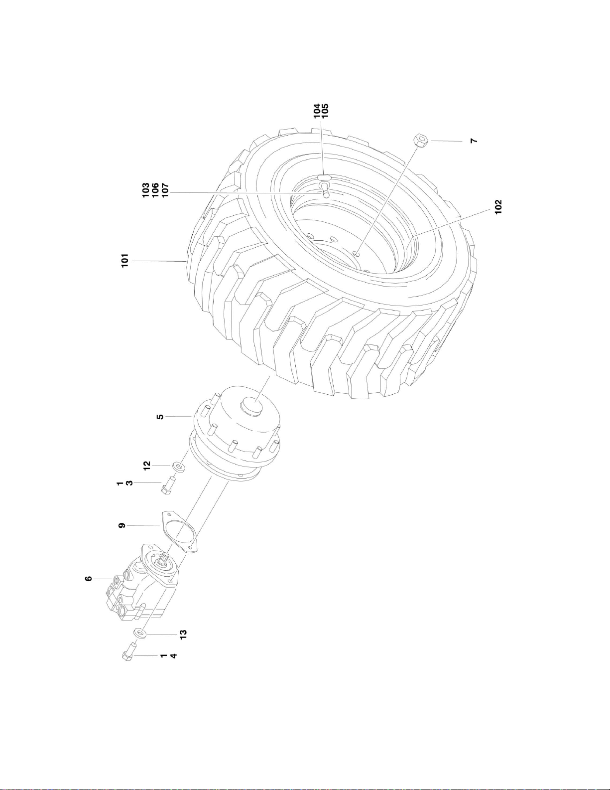
FIGURE 1-4. TIRE AND WHEEL DRIVE INSTALLATIONS
18 660SJ/600S 3121299
Page 19

SECTION 1 - FRAME
ITEM
PART NUMBER
QTY
DESCRIPTION
REV
Ref
WHEEL DRIVE INSTALLATIONS
1001149287
Ref
2WD
A 1001149288
Ref
4WD/2WS
A 1001149289
Ref
4WD/4WS
A
Ref
Note: 2WD Qty Shown. For 4WD, Double Qty Shown.
1 0100011
AR
Compound, Locking
3 0681810
4
Bolt 1/2in-13NC x 1-1/4in (Grade 8)
4 0682016
12
Bolt 5/8in-11NC x 2in (Grade 8)
5
2780269
2
Drive Hub Assembly (See DRIVE HUB ASSEMBLY for
Breakdown)
6 Ref
Drive Motor Assembly (See DRIVE MOTOR ASSEMBLY for
Breakdown)
6
3160349
2
2WD 6
3160350
2
4WD 7
3300106
18
Nut, Wheel
9 3960526
1
Gasket
12
4891800
4
Flatwasher 1/2in Hardened
13
4740393
12
Flatwasher 5/8in Hardened
Ref
TIRE AND WHEEL INSTALLATIONS OPTIONS
Ref
USA Built Machines:
1001101800
Ref
Pneumatic - OTR Tires (Available on All Specs except
Australian and CE Specs)
D
1001101802
Ref
Pneumatic W/Sealant - OTR Tires (Available on ANSI and
ANSI Export Specs Only)
C 0275860
Ref
Pneumatic Turf/Sand - Galaxy Tires (Available on ANSI
Specs Only)
1
1001101801
Ref
Foam-Filled - OTR Tires (Available on All Specs)
C
0274152
Ref
Foam-Filled - OTR Tires (Non-Marking) (Available on All
Specs)
1
Ref
China Built Machines:
1001101800
Ref
Pneumatic - OTR Tires (Available on ANSI Export and
Japanese Specs)
D
1001101801
Ref
Foam-Filled - OTR Tires (Available on All Specs)
C
Ref
Tire and Wheel Assembly Options:
1001097358
2
Pneumatic - OTR Tire (Right Side)
D 1001097357
2
Pneumatic - OTR Tire (Left Side)
D 1001097388
2
Pneumatic W/Sealant - OTR Tire (Right Side)
D 1001097387
2
Pneumatic W/Sealant - OTR Tire (Left Side)
D 4520674
4
Pneumatic Turf/Sand - Galaxy Tire (Not Shown)
A 1001097374
2
Foam-Filled - OTR Tire (Right Side)
F 1001097373
2
Foam-Filled - OTR Tire (Left Side)
F 4520340
2
Foam-Filled - OTR Tire (Non-Marking) (Right Side)
B 4520339
2
Foam-Filled - OTR Tire (Non-Marking) (Left Side)
B
Ref
Note: Assemblies may require ballast/foam filling to
manufacturer's specifications prior to installing on a
machine. Refer to Operation and Safety or Service and
Maintenance Manuals. Purchase individual tire and/or rim
only if able to foam fill tire and wheel assembly,
otherwise, purchase complete assembly.
Ref
Note: Turf/Sand Tires required additional chassis
counterweight. See SPECIAL OPTIONS SECTION before
installing this option.
101
Ref
Tire (1 Per Assembly) Options:
FIGURE 1-4. TIRE AND WHEEL DRIVE INSTALLATIONS
3121299 660SJ/600S 19
Page 20

ITEM
PART NUMBER
QTY
DESCRIPTION
REV
101
1001097351
4
Tire 39 x 15-22.5
101
4520256
4
Tire 41/18LL x 22.5 - Turf/Sand (1 Per Assembly)
102
Ref
Rim, Wheel (1 Per Assembly) Options:
102
1001097348
4
Rim, Wheel - 39 x 15-22.5 Tire (1 Per Assembly)
102
4520672
4
Rim, Wheel - Turf/Sand 22.5 x 14 (1 Per Assembly)
103
4640113
4
Valve, Air (1 Per Assembly)
104
Ref
Decal PSI Options:
104
1702701
4
Decal - 95 PSI
104
1701643
4
Decal - 70 PSI (Turf/Sand Tires 41/18LL x 22.5 Only)
105
1705364
AR
Decal - Tire Sealant (W/Sealant Only)
106
1300019
AR
Chemical, Tire Sealant (Green) (W/Sealant Only)
107
1120552
AR
Cap, Valve Stem (Green) (W/Sealant Only)
SECTION 1 - FRAME
20 660SJ/600S 3121299
Page 21

Page 22
SECTION 1 - FRAME
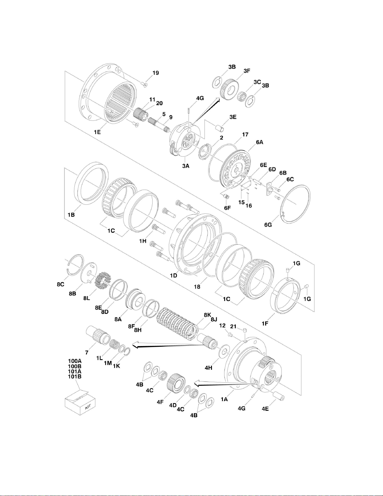
FIGURE 1-5. DRIVE HUB ASSEMBLY
22 660SJ/600S 3121299
Page 23

FIGURE 1-5. DRIVE HUB ASSEMBLY
ITEM
PART NUMBER
QTY
DESCRIPTION
REV
2780269
Ref
DRIVE HUB/BRAKE ASSEMBLY
C
1
See Note
1
Spindle/Housing Assembly (Note: Not Available - Purchase p/n
2780269 Complete Replacement. See 1A-1M for Available
Components.)
1A
7024729
1
Spindle
1B
70001119
1
Seal 1C
7024735
2
Bearing (Includes Cup and Cone)
1D
2780269
1
Housing (Note: Not Available for Purchase.)
1E
7024730
1
Ring, Gear
1F
7024744
1
Nut, Bearing
1G
See Note
2
Setscrew 1/4in-28NF x 1/2in (Note: Use Item 100A,100B,101A or
101B) 1H
7024732
9
Stud, Wheel
1K
7024125
1
Ring, Retaining
1L
7024124
1
Spring
1M
7024129
1
Thrustwasher
2 7024741
1
Thrustwasher
3
See Note
1
Carrier Assembly (Note: Not Available for Purchase. See 3A-3F for
Available Components.)
3A
7024725
1
Carrier
3B
7024127
6
Thrustwasher
3C
7024733
42
Bearing, Needle
3E
7024724
3
Shaft, Planet
3F
7024727
3
Gear, Planet
4
See Note
1
Planet Gear Sub-Assembly (Note: Not Available for Purchase. See
4A-4H for Available Components.)
4B
7024740
12
Thrustwasher
4C
7024734
84
Bearing, Needle
4D
7024736
3
Spacer, Thrust
4E
7024726
3
Shaft, Planet
4F
7024728
3
Gear, Planet
4G
7001913
6
Rollpin
4H
7024742
1
Thrustwasher
5 7017027
1
Ring, Retaining
6
See Note
1
Cover Assembly (Note: Not Available for Purchase. See 6A-6G for
Available Components.)
6A
7024731
1
Plate, Cover
6B
7017093
1
Cap, Disengage
6C
7000216
2
Bolt 1/2in-20NC x 1/2in
6D
7024739
1
Pin, Dowel
6E
7017095
1
O-Ring
6F
7017072
2
Plug, Pipe
6G
7024738
1
Ring, Retaining
7 7024722
1
Coupling
8
See Note
1
Brake, Input (Note: Not Available for Purchase. See 8A-8L for
Available Components.)
8A
70000782
1
Piston, Brake
8B
7024743
1
Plate, Pressure
8C
See Note
1
Ring, Retaining (Note: Use Item 101A or 101B)
8D
See Note
1
O-Ring (Note: Use Item 100B or 101A)
8E
See Note
1
Ring, Back-up (Note: Use Item 100B or 101A)
SECTION 1 - FRAME
3121299 660SJ/600S 23
Page 24

ITEM
PART NUMBER
QTY
DESCRIPTION
REV
8F
See Note
1
O-Ring (Note: Use Item 100B or 101A)
8H
See Note
1
Ring, Back-up (Note: Use Item 100B or 101A)
8J
7024764
8
Rotor, Brake
8K
7024764
9
Stator, Brake
8L
7024766
AR
Spring, Brake
9 7024721
1
Shaft, Input
11
7024723
1
Gear, Sun
12
See Note
1
Plug (Note: Not Available - Purchase Locally.)
15
See Note
1
Plate, ID (Not Shown) (Note: Not Available for Purchase.)
16
7000281
4
Screw, Drive
17
7024134
1
O-Ring 18
7024744
1
O-RIng 19
7017022
3
Screw, Countersunk 3/8in-16NC
20
7024737
1
Ring, Retaining
21
See Note
1
Plug (Note: Not Available - Purchase Locally.)
100
Ref
Seal Kit Options:
100A
7024744
1
Hub Seal Kit (Includes Items 1B, 1F, 1G, 17, 18 & 19)
100B
7024765
1
Brake Seal Kit (Includes Items 1G, 8C, 8D, 8E, 8F & 8H)
101
Ref
Repair Kit Options:
101A
7024764
1
Brake Lining Kit (Includes Items 1G, 8C, 8D, 8F, 8E, 8H, 8J &
8K) 101B
7024766
1
Brake Spring Kit (Includes Items 1G, 8C & 8L)
SECTION 1 - FRAME
24 660SJ/600S 3121299
Page 25

Page 26
SECTION 1 - FRAME
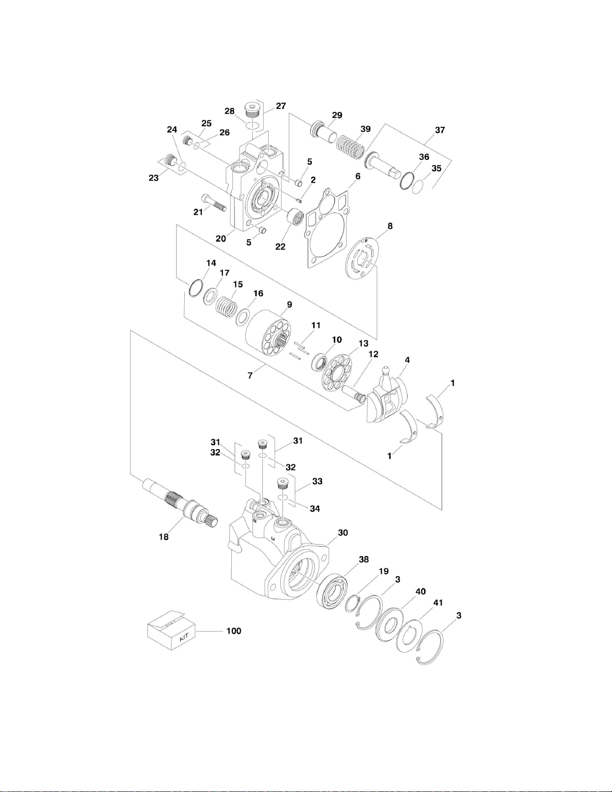
FIGURE 1-6. DRIVE MOTOR ASSEMBLY
26 660SJ/600S 3121299
Page 27

FIGURE 1-6. DRIVE MOTOR ASSEMBLY
ITEM
PART NUMBER
QTY
DESCRIPTION
REV
Ref
DRIVE MOTOR ASSEMBLY
3160349
Ref
2WD
B 3160350
Ref
4WD
B 1 7022302
2
Bearing, Journal
2 7007446
1
Pin 3
7007438
2
Ring, Retaining
4 70000794
1
Swashplate
5 See Note
2
Pin (Note: Not Available for Purchase.)
6 7022328
1
Gasket
7 7027740
1
Cylinder Block Kit (Includes Items 9-17)
8 7024862
1
Plate, Valve
9 7027740
1
Block, Cylinder
10
7027740
1
Guide, Slipper Retainer
11
7021275
3
Pin, Slipper Hold Down
12
7024865
9
Piston Assembly
13
7027740
1
Retainer, Slipper
14
7022311
1
Ring, Retaining
15
7024867
1
Spring
16
7022313
1
Washer
17
7022314
1
Retainer, Spring
18
7023910
1
Shaft 19
7007439
1
Ring, Retaining
20
70000795
1
Cap, End - Axial
21
7022368
5
Screw
22
7021249
1
Bearing, Needle
23
2220886
1
Plug (Includes Item 24)
24
7022328
1
O-Ring
25
2220883
1
Plug (Includes Item 26)
26
7022328
1
O-Ring
27
7027419
2
Plug (Includes Item 28)
28
7022328
2
O-Ring
29 Ref
Seat, Spring Options:
29
7024853
1
2WD/2WS
29
7022372
1
2WD/4WS, 4WD/2WS & 4WD/4WS
30
See Note
1
Housing (Note: Not Available - Purchase Complete Drive Motor
Assembly.)
31
2220883
2
Plug (Items Item 32)
32
7022328
2
O-Ring
33
2220886
1
Plug (Items Item 34)
34
7022328
1
O-Ring
35
7022328
1
O-Ring
36
7022328
1
Ring, Seal
37
7024871
1
Piston, Servo
38
7007437
1
Bearing
39
7022326
1
Spring
40
7022328
1
Seal, Lip
41
7022371
1
Washer, Support
100
7022328
1
Seal Kit (Includes Items 6, 24, 26, 28, 32, 34, 35, 36 & 40)
SECTION 1 - FRAME
3121299 660SJ/600S 27
Page 28
SECTION 1 - FRAME
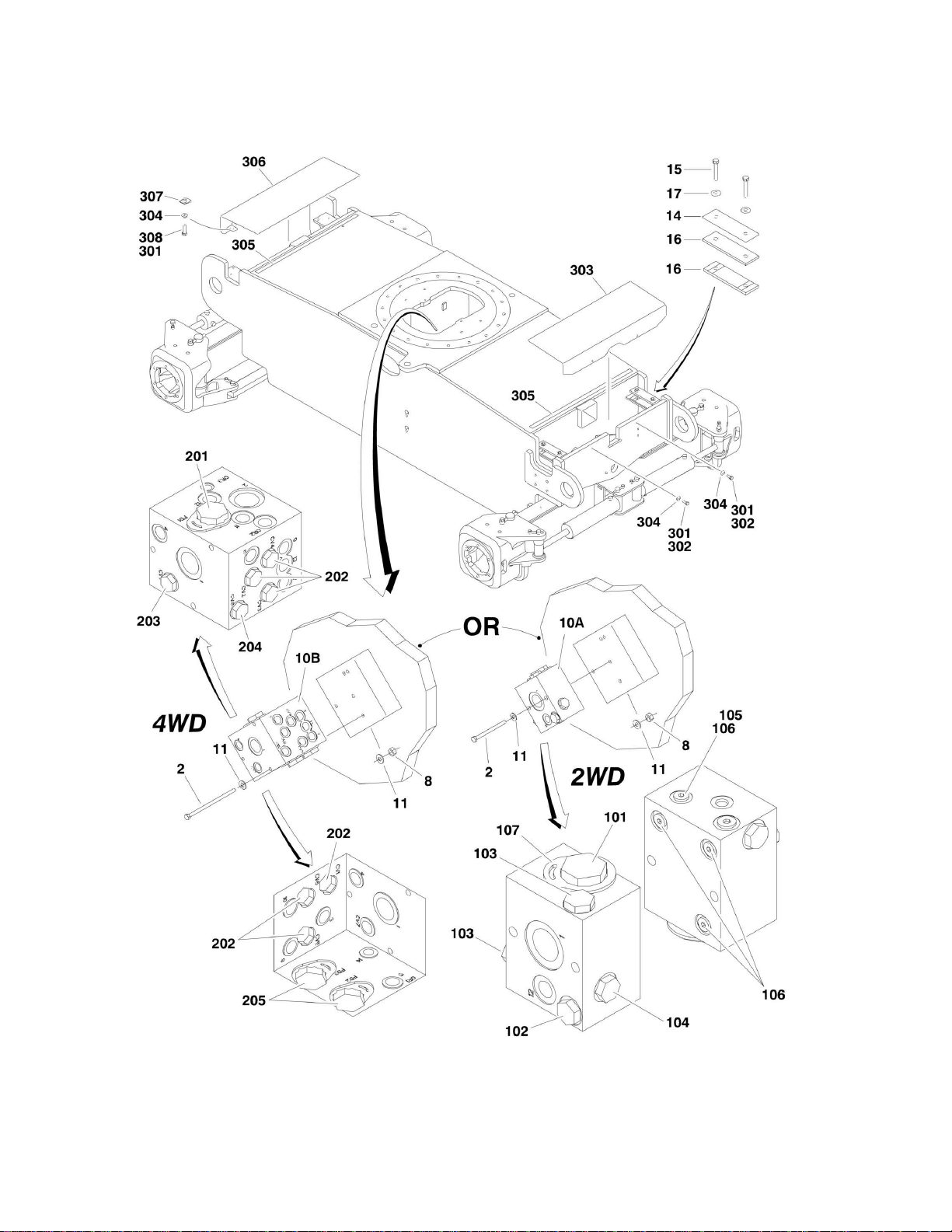
FIGURE 1-7. DRIVE VALVES AND SHIELDS INSTALLATION (FRAME MOUNTED)
28 660SJ/600S 3121299
Page 29

SECTION 1 - FRAME
ITEM
PART NUMBER
QTY
DESCRIPTION
REV
Ref
DRIVE VALVES INSTALLATION OPTIONS:
1001149287
Ref
2WD
A 1001149288
Ref
4WD/2WS
A 1001149289
Ref
4WD/4WS
A 2
Ref
Bolt 5/16in-18NC Options:
2 0641530
2
3-3/4inin Length (2WD)
2 0641552
3
6-1/2in Length (4WD)
8 3311505
AR
Locknut 5/16in-18NC
10 Ref
Flow Divider Valve Assembly Options:
10A
1001100120
1
2WD (See Items 101-107 for Breakdown)
10B
1001098503
1
4WD (See Items 201-207 for Breakdown)
11
4711500
AR
Flatwasher 5/16in Thin
14 Ref
Bar, Clamping
14
Not Required
0
2WD
14
0363012
2
4WD
15
0641618
4
Bolt 3/8in-16NC x 2-1/4in
16
3340911
4
Rubber, Clamp
17
4751600
4
Flatwasher 3/8in Regular
1001100120
Ref
FLOW DIVIDER ASSEMBLIES (2WD)
A
101
7023933
1
Valve, Cartridge (Flow Divider)
101
7021625
1
Seal Kit - Flow Divider Cartridge
102
7024892
1
Valve, Cartridge (Check)
102
7023936
1
Seal Kit - Check Cartridge
103
7022397
2
Valve, Cartridge (Check)
103
7022399
2
Seal Kit - Check Cartridge
104
7023935
1
Valve, Cartridge (Check)
104
7023936
1
Seal Kit - Check Cartridge
105
70002063
1
Orifice
106
7017406
4
Plug 107
70000781
1
Lock Down Kit
1001098503
Ref
FLOW DIVIDER ASSEMBLIES (4WD)
A
201
7023933
1
Valve, Cartridge (Flow Divider)
201
7021625
1
Seal Kit - Flow Divider Cartridge
202
70003408
6
Valve, Cartridge (Check)
202
7022399
6
Seal Kit - Check Cartridge
203
7023935
1
Valve, Cartridge (Check)
203
7023936
1
Seal Kit - Check Cartridge
204
7024892
1
Valve, Cartridge (Check)
204
7023936
1
Seal Kit - Check Cartridge
205
7023917
2
Valve, Cartridge (Flow Divider)
205
7021625
2
Seal Kit - Flow Divider Cartridge
206
70002063
1
Plug, Orifice
207
70002064
2
Plug, Orifice
Ref
FRAME SHIELDS INSTALLATION
1001150994
Ref
2WS
A 1001150995
Ref
4WS
A
301
0100011
AR
Compound, Locking
302
0641607
AR
Bolt 3/8in - 16NC x 7/8in
303
1001150845
1
Cover (Front)
304
4891600
AR
Flatwasher, 3/8in Hardened
FIGURE 1-7. DRIVE VALVES AND SHIELDS INSTALLATION (FRAME MOUNTED)
3121299 660SJ/600S 29
Page 30

ITEM
PART NUMBER
QTY
DESCRIPTION
REV
305
4280296
AR
Trim 306
1001150845
1
Cover (Rear) (4WS Only)
307
83683307
2
Nut, Tinnerman (4WS Only)
308
0641610
1
Bolt 3/8in - 16NC x 1-1/4in (4WS Only)
SECTION 1 - FRAME
30 660SJ/600S 3121299
Page 31

Page 32

SECTION 1 - FRAME
FIGURE 1-8. TOW PACKAGE INSTALLATION (OPTIONAL)
32 660SJ/600S 3121299
Page 33

SECTION 1 - FRAME
ITEM
PART NUMBER
QTY
DESCRIPTION
REV
Ref
TOW PACKAGE INSTALLATION
Ref
USA Built Machines:
1001150571
Ref
ANSI Spec
C 1001150570
Ref
CSA Spec
C 1001150569
Ref
CE Spec
A
Ref
China Built Machines:
1001150571
Ref
ANSI Export Spec
C
101
0100011
AR
Compound, Locking
102
0270528
1
Bar Assembly (See Items 201-221 for Breakdown)
103
0641516
2
Bolt 5/16in-18NC x 2in
104
Ref
Decal - Crushing Options:
104
1704578
2
ANSI/CSA Spec
104
1706960
2
CE Spec
105
Ref
Decal - Towing Instructions Options:
105
1705090
1
ANSI Spec
105
1705820
1
CSA Spec
105
Not Required
1
CE Spec
106
Ref
Nameplate - Steer/Tow Select Valve Options:
106A
3250872
1
ANSI Spec
106B
1704272
1
CSA Spec
106C
1706957
1
CE Spec
107
Ref
Screw, Self-Tapping #6-32NF x 1/2in Options:
107
3940604
4
ANSI/CSA Spec
107
Not Required
4
CE Spec
108
4420051
2 ft/.61m
Tape, Safety
109
4640261
1
Valve, Select
0270528
Ref
TOW BAR ASSEMBLY
A
201
0100011
AR
Compound, Locking
202
0362910
1
Pintle, Draw Eye
203
0642010
4
Bolt 5/8in-11NC x 1-1/4in
204
0721004
2
Screw, Hex Machine
205
0741607
24
Screw, Countersunk 3/8in-16NC x 7/8in
206
1060584
6
Cable, Lanyard
207
3420372
2
Pin, Cotter
208
3420447
1
Pin, Towing
209
3421565
2
Pin, Snap
210
3422841
2
Pin 211
3422847
1
Pin 212
3572009
2
Plate, Slide Stop
213
3572010
2
Plate, Slide Stop
214
3572011
2
Plate, Slide Stop
215
3572012
2
Plate, Slide Stop
216
3760170
8
Ring, Split
217
4568133
1
Tube, Tow Bar
218
4740036
1
Flatwasher
219
4751000
2
Flatwasher #10 Regular
220
4846295
1
Tow Bar Attach Weldment
221
4846296
1
Pintle Attach Weldment
FIGURE 1-8. TOW PACKAGE INSTALLATION (OPTIONAL)
3121299 660SJ/600S 33
Page 34

Page 35

SECTION 2 - TURNTABLE
SECTION 2 - TURNTABLE
3121299 660SJ/600S 35
Page 36

SECTION 2 - TURNTABLE
FIGURE 2-1. CONTROL VALVES INSTALLATIONS
36 660SJ/600S 3121299
Page 37

SECTION 2 - TURNTABLE
ITEM
PART NUMBER
QTY
DESCRIPTION
REV
Ref
USAGE CHART:
Ref
USA Built Machines (SN 0300171769 through 0300181891)
Ref
China Built Machines (SN B300000869 to Present)
Ref
CONTROL VALVES INSTALLATIONS
Ref
USA Built Machines (SN 0300171769 through 0300181891)
1001145279
Ref
Control Valves Installations 600S (2WS)
A 1001145280
Ref
Control Valves Installations 600S (4WS)
A 1001145281
Ref
Control Valves Installations 660SJ (2WS)
A 1001145282
Ref
Control Valves Installations 660SJ (4WS)
A
Ref
China Built Machines:
1001145279
Ref
Control Valves Installations 600S (2WS)
A 1001145280
Ref
Control Valves Installations 600S (4WS)
A 1001145281
Ref
Control Valves Installations 660SJ (2WS)
A 1001145282
Ref
Control Valves Installations 660SJ (4WS)
A
1
1001091303
1
Main Control Valve Assy Options (See MAIN CONTROL
VALVE ASSEMBLY for Breakdown)
6
2120209
1
Hydraulic Pressure Filter Assembly
6A
2120210
1
Element, Filter
6B
7020020
1
Indicator, Clogged Filter
6C
70000934
1
O-Ring, Filter Bowl (Not Shown)
7
1001099391
1
Valve Assembly (2 Speed/Brake) (See Items 101-103 for
Breakdown)
9 Ref
Valve Kit (Articulating Jib) Options:
9 Not Required
0
Valve Kit 600S
9
4640921
1
Valve Kit 660SJ (See ACCESSORY VALVE ASSEMBLY for
Breakdown)
10 Ref
4WS Valve Kit Options:
10
Not Required
0
2WS Machines
10
4640922
1
4WS Machines (See ACCESSORY VALVE ASSEMBLY for
Breakdown)
12
4711600
3
Flatwasher 3/8in Thin
15
4711500
1
Flatwasher 5/16in Thin
16
3311501
1
Nut 5/16in-18NC
17
2120164
1
Return Filter Assembly
17A
2120149
1
Element, Filter
17B
7020021
1
Switch, Clog Indicator
19
0651406
3
Bolt 1/4in-28NF x 3/4in
20
4711400
17
Flatwasher 1/4in Thin
22
0641416
2
Bolt 1/4in-20NC x 2in
26
3311405
2
Locknut 1/4in-20NC
28
0641608
3
Bolt 3/8in-16NC x 1in
29
0140001
1
Horn
30 Ref
Harness Assembly (Jib Control) Options (See ELECTRICAL
SECTION for Breakdown):
30
Not Required
0
Harness Assembly 600S
30
4921927
1
Harness Assembly 660SJ
31 Ref
Harness Assembly (4WS Control) Options (See ELECTRICAL
SECTION for Breakdown):
31
Not Required
0
2WS Machines
31
4921928
1
4WS Machines
34
4060918
40 in/10m
Flex-Trim
FIGURE 2-1. CONTROL VALVES INSTALLATIONS
3121299 660SJ/600S 37
Page 38

ITEM
PART NUMBER
QTY
DESCRIPTION
REV
36
0100011
AR
Compound, Locking
1001099391
Ref
VALVE ASSEMBLY (DUAL SELECT BRAKE/2 SPEED)
A
101
7012941
1
Cartridge without Coil
101
7010543
1
Seal Kit - 7012941 Cartridge
101
7012944
1
Coil 102
7012995
1
Cartridge without Coil
102
7012518
1
Seal Kit - 7012995 Cartridge
102
7012943
1
Coil 103
70002209
1
Plug, Orifice (Not Shown - Access to orifice is through port T)
1001150423
Ref
AUXILIARY PUMP INSTALLATION
A
201
0100011
AR
Compound, Locking
202
0811610
2
Bolt 3/8in-16NC x 1-1/4in
203
1001137458
1
Auxiliary Pump Assembly (See Items 301-307 for Breakdown)
1001137458
Ref
AUXILIARY PUMP ASSEMBLY
A
301
70003995
1
Base 302
70003996
1
Pump 303
70003997
4
Screw 1/4in-20NC x 3in
304
70003998
1
Motor 305
70003999
1
Bracket
306
70004000
2
Screw 3/8in-16NC x 1in
307
7026330
1
Seal, Shaft
SECTION 2 - TURNTABLE
38 660SJ/600S 3121299
Page 39

Page 40

SECTION 2 - TURNTABLE
FIGURE 2-2. CONTROL VALVES INSTALLATIONS
40 660SJ/600S 3121299
Page 41

SECTION 2 - TURNTABLE
ITEM
PART NUMBER
QTY
DESCRIPTION
REV
Ref
USAGE CHART:
Ref
USA Built Machines (SN 0300181891 to Present)
Ref
CONTROL VALVES INSTALLATIONS
1001160095
Ref
Control Valves Installations 600S (2WS)
A 1001160096
Ref
Control Valves Installations 600S (4WS)
A 1001159731
Ref
Control Valves Installations 660SJ (2WS)
A 1001160192
Ref
Control Valves Installations 660SJ (4WS)
A 1 0100011
AR
Compound, Locking
3 0641416
2
Bolt 1/4in-20NC x 2in
5 0641608
3
Bolt 3/8in-16NC x 1in
6 0651406
3
Bolt 1/4in-28NF x 3/4in
8 2120164
1
Return Filter Assembly
8A
2120149
1
Element, Filter
8B
7020021
1
Switch, Clog Indicator
9 2120209
1
Hydraulic Pressure Filter Assembly
9A
2120210
1
Element, Filter
9B
7020020
1
Indicator, Clogged Filter
9C
70000934
1
O-Ring, Filter Bowl (Not Shown)
11
4060918
40 in/10m
Flex-Trim
12
4711400
15
Flatwasher 1/4in Thin
14
4711600
3
Flatwasher 3/8in Thin
16
1001099391
1
Valve Assembly (2 Speed/Brake) (See Items 101-103 for
Breakdown)
18 Ref
Main Control Valve Assy Options (See MAIN CONTROL VALVE
ASSEMBLY for Breakdown):
18
1001152886
1
Main Control Valve Assy 600S (2WS) & 660SJ (2WS)
18
1001152560
1
Main Control Valve Assy 600S (4WS) & 660SJ (4WS)
1001099391
Ref
VALVE ASSEMBLY (DUAL SELECT BRAKE/2 SPEED)
A
101
7012941
1
Cartridge without Coil
101
7010543
1
Seal Kit - 7012941 Cartridge
101
7012944
1
Coil 102
7012995
1
Cartridge without Coil
102
7012518
1
Seal Kit - 7012995 Cartridge
102
7012943
1
Coil 103
70002209
1
Plug, Orifice (Not Shown - Access to orifice is through port T)
1001150423
Ref
AUXILIARY PUMP INSTALLATION
A
201
0100011
AR
Compound, Locking
202
0811610
2
Bolt 3/8in-16NC x 1-1/4in
203
1001137458
1
Auxiliary Pump Assembly (See Items 301-307 for Breakdown)
1001137458
Ref
AUXILIARY PUMP ASSEMBLY
A
301
70003995
1
Base 302
70003996
1
Pump 303
70003997
4
Screw 1/4in-20NC x 3in
304
70003998
1
Motor 305
70003999
1
Bracket
306
70004000
2
Screw 3/8in-16NC x 1in
307
7026330
1
Seal, Shaft
FIGURE 2-2. CONTROL VALVES INSTALLATIONS
3121299 660SJ/600S 41
Page 42

SECTION 2 - TURNTABLE
FIGURE 2-3. MAIN CONTROL VALVE ASSEMBLY
42 660SJ/600S 3121299
Page 43

SECTION 2 - TURNTABLE
ITEM
PART NUMBER
QTY
DESCRIPTION
REV
Ref
USAGE CHART:
Ref
USA Built Machines (SN 0300171769 through 0300181891)
Ref
China Built Machines (SN B300000869 to Present)
1001091303
Ref
MAIN CONTROL VALVE ASSEMBLIES
A 1 7017410
1
Cartridge, Without Coil
1 7012967
1
Seal Kit - 7017410 Cartridge
1A
7012944
1
Coil 2
7017464
1
Cartridge, Pressure Sensing
2 7012518
1
Seal Kit
3 7012912
1
Cartridge (Main Relief)
3 7012998
1
Seal Kit
4 70001976
1
Control Valve Assembly (Platform Level)
4 7012773
1
Seal Kit
4A
7018991
2
Coil 4A
7018912
2
Nut, Coil
5 7012914
1
Cartridge, Check Valve
5 7012918
1
Seal Kit - 7012914 Cartridge
6 7012914
1
Cartridge, Check Valve
6 7012918
1
Seal Kit - 7012914 Cartridge
7 7012912
1
Cartridge, Relief Valve (Platform Level Backward)
7 7012998
1
Seal Kit - 7012912 Cartridge
8 7012912
1
Cartridge, Relief Valve (Platform Level Forward)
8 7012998
1
Seal Kit - 7012912 Cartridge
9 7012989
1
Cartridge, Flow Control
9
7012953
1
Seal Kit - 7012989 Cartridge
10
70001976
1
Control Valve Assembly (Platform Rotate)
10
7012773
1
Seal Kit
10A
7018991
2
Coil
10A
7018912
2
Nut, Coil
11
70000579
1
Control Valve Assembly (Upper Tele):
11
70000583
1
Seal Kit Options
11A
70000582
1
Coil
11A
70000580
1
Nut, Coil
12
7012775
1
Control Valve Assembly (Flow Control)
12
7012773
1
Seal Kit
12A
7012772
2
Coil
12A
7018912
2
Nut, Coil
12A
7024015
2
Pipe, Pole
13
7010542
1
Cartridge, Shuttle
13
7010543
1
Seal Kit - 7010542 Cartridge
14
7010542
1
Cartridge, Shuttle
14
7010543
1
Seal Kit - 7010542 Cartridge
15
7010542
1
Cartridge, Shuttle
15
7010543
1
Seal Kit - 7010542 Cartridge
16
7010542
1
Cartridge, Shuttle
16
7010543
1
Seal Kit - 7010542 Cartridge
17
7010542
1
Cartridge, Shuttle
17
7010543
1
Seal Kit - 7010542 Cartridge
18
7012912
1
Cartridge, Relief Valve (Upper Lift Down)
18
7012998
1
Seal Kit - 7012912 Cartridge
FIGURE 2-3. MAIN CONTROL VALVE ASSEMBLY
3121299 660SJ/600S 43
Page 44

ITEM
PART NUMBER
QTY
DESCRIPTION
REV
19
7012775
1
Control Valve Assembly (Upper Lift)
19
7012773
1
Seal Kit
19A
7012772
2
Coil
19A
7018912
2
Nut, Coil
19A
7024015
2
Pipe, Pole
20
7012775
1
Control Valve Assembly (Swing)
20
7012773
1
Seal Kit
20A
7012772
2
Coil
20A
7018912
2
Nut, Coil
20A
7024015
2
Pipe, Pole
21
7012912
1
Cartridge, Relief Valve (Swing)
21
7012998
1
Seal Kit - 7012912 Cartridge
22
7012774
1
Control Valve Assembly (Steer)
22
7012773
1
Seal Kit
22A
7012772
2
Coil
22A
7018912
2
Nut, Coil
22A
7024014
2
Pipe, Pole
23
7012912
1
Cartridge, Relief Valve (Steer Left)
23
7012998
1
Seal Kit - 7012912 Cartridge
24
7012912
1
Cartridge, Relief Valve (Steer Right)
24
7012998
1
Seal Kit - 7012912 Cartridge
25
7018941
2
Orifice
30
4460499
15
Connector, Din with Diode (Part of Valve Harness)
31
2220885
2
Plug
2901763
Ref
ROTATE SANDWICH VALVE KIT
A
51
7021310
1
Block, Valve
SECTION 2 - TURNTABLE
44 660SJ/600S 3121299
Page 45

Page 46

SECTION 2 - TURNTABLE
FIGURE 2-4. MAIN CONTROL VALVE ASSEMBLY
46 660SJ/600S 3121299
Page 47

SECTION 2 - TURNTABLE
ITEM
PART NUMBER
QTY
DESCRIPTION
REV
Ref
USAGE CHART:
Ref
USA Built Machines (SN 0300181891 to Present)
Ref
MAIN CONTROL VALVE ASSEMBLIES
1001152886
Ref
Main Control Valve Assemblies 600S (2WS) & 660SJ (2WS)
B 1001152560
Ref
Main Control Valve Assemblies 600S (4WS) & 660SJ (4WS)
C
110
70004652
1
Cartridge, Valve Less Coil (Dump)
110
70023867
1
Seal Kit - 70004652 Valve
115
70004653
1
Coil 115
70004654
1
Nut, Coil
120
70004655
1
Cartridge, Valve
120
70004656
1
Seal Kit - 70004655 Valve
130
70004657
1
Valve, Cartridge Less Coil
130
70004594
1
Seal Kit - 70004657 Valve
135
70004595
1
Coil 135
70004597
1
Nut, Coil
135
70004596
1
O-Ring, Solenoid Tube
140
70004659
1
Valve, Solenoid Less Cartridge (Front Steer)
140
70004660
1
Seal Kit - 70004660 Valve
145
80434249
2
Coil 145
70004661
1
Nut, Coil
145
70024457
1
O-Ring, Solenoid Tube (Upper)
145
70004662
1
O-Ring, Solenoid Tube (Lower)
150
70023859
5
Valve, Cartridge
170
70004459
1
Valve, Directional Control (Telescope)
170
7012773
1
Seal Kit - 70004459 Valve
170
70004460
2
Coil
170
7021375
2
Nut, Coil
170
70004461
2
O-Ring, Solenoid Tube
190
70004666
2
Valve, Directional Control (Lift & Swing)
190
7012773
2
Seal Kit - 70004666 Valve (1 Per Assy)
190
70004463
4
Coil (2 Per Assy)
190
7021375
4
Nut, Coil (2 Per Assy)
190
70004461
1
O-Ring, Solenoid Tube (2 Per Assy)
200
70003019
3
Valve, Cartridge
200
70004052
3
Seal Kit - 70003019 Valve (1 Per Valve)
210
70003019
2
Valve, Cartridge
210
70004052
2
Seal Kit - 70003019 Valve (1 Per Valve)
220
70004667
1
Plate, Cover
230
70004670
1
Plug 240
70004668
1
Plug 700
70004671
1
Valve, Directional Control (Rear Steer) (4WS Machines Only)
700
70004672
1
Seal Kit - 70004671 Valve
710
70004673
2
Coil 730
70004674
2
Valve, Cartridge
740
See Note
4
Capscrew M5 x 60 (Note: Not Available - Purchase Locally)
801
See Note
1
Bolt Kit
802
3931032
12
Capscrew #10-24 X 2
803
See Note
2
O-Ring (Note: Not Available for Purchase)
804
See Note
1
O-Ring (Note: Not Available for Purchase)
805
See Note
4
Plug #4 (Not Shown) (Note: Not Available for Purchase)
FIGURE 2-4. MAIN CONTROL VALVE ASSEMBLY
3121299 660SJ/600S 47
Page 48

ITEM
PART NUMBER
QTY
DESCRIPTION
REV
806
See Note
4
Plug #6 (Not Shown) (Note: Not Available for Purchase)
807
See Note
1
Plug #8 (Not Shown) (Note: Not Available for Purchase)
809
See Note
2
O-Ring (Note: Not Available for Purchase)
SECTION 2 - TURNTABLE
48 660SJ/600S 3121299
Page 49

Page 50

SECTION 2 - TURNTABLE
FIGURE 2-5. ACCESSORY VALVE ASSEMBLY
50 660SJ/600S 3121299
Page 51

SECTION 2 - TURNTABLE
ITEM
PART NUMBER
QTY
DESCRIPTION
REV
Ref
ACCESSORY VALVE ASSEMBLIES
4640921
Ref
ARTICULATING JIB VALVE ASSEMBLY
D 1 7012965
1
Cartridge, Flow Control
1 7012953
1
Seal Kit - 7012965 Cartridge
2 70001976
1
Directional Control Valve Assembly
2 7012773
1
Seal Kit
2A
7018945
4
O-Ring
2B
7018912
2
Nut 2C
7012772
2
Coil 3
7017421
1
Cartridge, Relief
3 7012998
1
Seal Kit - 7017421 Cartridge
4 7017422
1
Cartridge, Relief
4 7012998
1
Seal Kit - 7017422 Cartridge
5 4460499
2
Connector, DIN with Diode (Not Shown - Part of Valve Harness)
6
7012777
4
Capscrew, Socket Head 5/16in-18NC x 2-1/4in (Used to Mount
Valve Assembly)
7
7018942
4
Capscrew, Socket Head #10-24NC x 2in
8 7012776
2
O-Ring (Used to Mount Main Valve)
4640922
Ref
4WS VALVE ASSEMBLY
B
101
7017420
1
Cartridge, Relief
101
7012998
1
Seal Kit - 7017420 Cartridge
102
7012774
1
Directional Control Valve Assembly
102
7012773
1
Seal Kit
102A
7018945
4
O-Ring
102B
7018912
2
Nut
102C
7012772
2
Coil
103
7018946
4
Capscrew, Socket Head #10-24NC x 5in (Used to Mount Main
Valve)
104
7018942
4
Capscrew, Socket Head #10-24NC x 2in
105
7018948
4
O-Ring (Used to Mount Main Valve)
106
7018947
1
Plate, O-Ring
FIGURE 2-5. ACCESSORY VALVE ASSEMBLY
3121299 660SJ/600S 51
Page 52

SECTION 2 - TURNTABLE
FIGURE 2-6. SWING DRIVE, TURNTABLE BEARING AND LOCK INSTALLATIONS
52 660SJ/600S 3121299
Page 53

SECTION 2 - TURNTABLE
ITEM
PART NUMBER
QTY
DESCRIPTION
REV
1001150390
Ref
SWING DRIVE INSTALLATION
D 1 0100019
AR
Compound, Locking
2 Ref
Bolt Options:
2 Ref
USA Built Machines
2
0642018
1
Bolt 5/8in - 11NC x 2-1/4in (SN 0300171769 through
0300179726)
2
0682018
1
Bolt 5/8in - 11NC x 2-1/4in (Grade 8) (SN 0300179727 to
Present)
2
0682018
1
China Built Machines (Bolt 5/8in - 11NC x 2-1/4in (Grade 8)
3 0682216
4
Bolt 3/4in - 10NC x 2in Grade 8
4 3312002
1
Nut, Jam 5/8in - 11NC
5 3900293
1
Capscrew 1in x 1-1/4in
6 4740057
4
Flatwasher, Hardened
7
1001101060
1
Swing Hub Assembly (See SWING MOTOR/HUB ASSEMBLY for
Breakdown)
8
4071009
1
Shim
1001150391
Ref
TURNTABLE BEARING AND REMOTE LUBE INSTALLATION
C
101
0100019
AR
Compound, Locking
102
0440207
1
Bearing, Turntable
103
0682018
36
Bolt 5/8in - 11NC x 2-1/4in Grade 8
104
3020029
AR
Lubricant
105
4892000
36
Flatwasher 5/8in Hardened
106
0100011
AR
Compound, Locking
107
1001149927
1
Hose (Includes Grease Fitting and Adapter Fittings)
1001151203
Ref
TURNTABLE LOCK INSTALLATION
B
201
3421627
1
Pin 202
3421565
1
Pin, Snap
203
3760170
2
Ring, Quick Release
204
1260017
9 in/23cm
Chain
FIGURE 2-6. SWING DRIVE, TURNTABLE BEARING AND LOCK INSTALLATIONS
3121299 660SJ/600S 53
Page 54

SECTION 2 - TURNTABLE
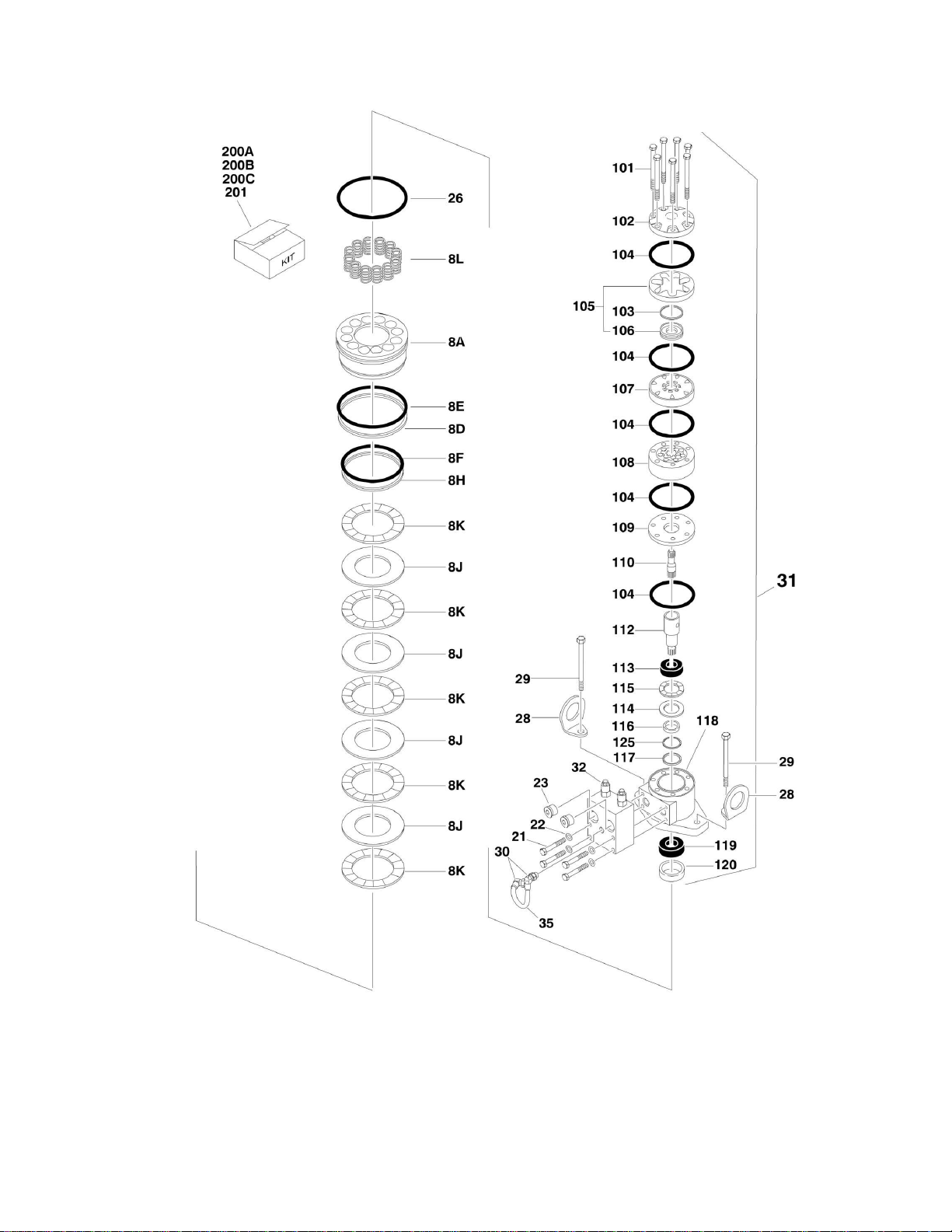
FIGURE 2-7. SWING MOTOR/HUB ASSEMBLY
54 660SJ/600S 3121299
Page 55
SECTION 2 - TURNTABLE
3121299 660SJ/600S 55
Page 56

ITEM
PART NUMBER
QTY
DESCRIPTION
REV
1001101060
Ref
SWING MOTOR/HUB ASSEMBLY
A
1
See Note
1
Housing/Shaft Assembly (Note: Not Available - Purchase
Individual Components.)
1A
7010492
1
Shaft, Output
1B
7000228
1
Seal, Lip
1C
7000255
1
Bearing Kit (Includes Cup and Cone)
1E
7000257
1
Bearing Kit (Includes Cup and Cone)
1G
7024762
1
Housing
1H
7007633
1
Washer, Thrust
1I
7000229
1
Ring, Retaining
1J
7017072
1
Plug, Pipe
2 7000246
1
Gear, Internal
3 80424002
1
Carrier Assembly
4 7000248
1
Gear, Ring
5 7000230
1
O-Ring 5A
7017070
1
O-Ring 6
1001101060
1
Housing, Brake (Note: Not Available - Purchase Complete Assy)
8 70002065
1
Gear, Sun
8A
70000782
1
Piston 8D
70002070
1
O-Ring 8E
70002071
1
Ring, Back-up
8F
70002073
1
O-Ring 8H
70002072
1
Ring, Back-up
8J
70002067
4
Disc, Rotor
8K
70002068
5
Disc, Stator
8L
70002066
14
Spring 11
7000253
2
Washer, Thrust
12
7000217
12
Bolt 3/8in-16NC x 2-1/4in (Grade 8)
13
7017080
4
Pin, Dowel
20
7017072
1
Plug, Pipe
21
7024704
4
Bolt 5/16in-18NC x 2in (Grade 8)
22
See Note
4
Lockwasher (Note: Not Available for Purchase.)
23
7017023
2
Plug, Pipe
24
See Note
1
Plate, ID (Note: Not Available for Purchase.)
25
7000281
2
Screw, Drive
26
7024763
1
O-Ring 28
See Note
2
Lug, Lifting (Note: Not Available for Purchase.)
29
70002069
2
Bolt 1/2in-13NC x 2in (Grade 8)
30
7017085
2
Elbow 31
70002075
1
Motor Assembly (See Items 101-125 for Breakdown)
32
7024784
1
Valve Assembly - Complete (No Serviceable Parts)
35
70002074
1
Tube 44
7017028
1
Ring, Internal Retaining
70002075
Ref
MOTOR ASSEMBLY
101
7024454
5
Bolt 102
7004035
1
Cover, End
103
7023318
1
Seal, Commutator
104
7004036
5
Seal, Ring
105
7024453
1
Commutator and Ring Assembly
106
7024453
1
Ring
SECTION 2 - TURNTABLE
FIGURE 2-7. SWING MOTOR/HUB ASSEMBLY
56 660SJ/600S 3121299
Page 57

SECTION 2 - TURNTABLE
ITEM
PART NUMBER
QTY
DESCRIPTION
REV
107
7024379
1
Manifold
108
7024455
1
Rotor Set
109
7024380
1
Plate, Wear
110
7024456
1
Link, Drive
112
7024458
1
Shaft, Coupling
113
7024381
1
Bearing, Inner
114
7004043
1
Washer, Thrust
115
7004044
1
Bearing, Thrust
116
7004049
1
Seal, Inner
117
7004045
1
Washer, Back-up
118
7024457
1
Housing
119
7024390
1
Bearing, Outer
120
7004047
1
Seal 125
80424043
1
Washer, Back-up
Ref
KIT OPTIONS:
200
Ref
Seal Kit Options:
200A
7024100
1
Swing Hub (Includes Items 1B, 1I, 5, 5A & 11)
200B
70002086
1
Swing Brake (Includes Items 8D, 8E, 8F, 8H & 26)
200C
7024396
1
Swing Motor (Includes Items 103, 104, 116, 117, 120 & 125)
201
70002085
1
Disc Kit - Swing Brake (Includes Items 8J & 8K)
3121299 660SJ/600S 57
Page 58

SECTION 2 - TURNTABLE
FIGURE 2-8. DEUTZ D2011 ENGINE INSTALLATION
58 660SJ/600S 3121299
Page 59

SECTION 2 - TURNTABLE
3121299 660SJ/600S 59
Page 60

ITEM
PART NUMBER
QTY
DESCRIPTION
REV
Ref
DEUTZ D2011 ENGINE INSTALLATIONS
Ref
USA Built Machines:
Ref
2WD
1001151341
Ref
Tier IVi Engines (All Specs Except ANSI and CSA Specs)
B 1001151636
Ref
Tier IVi Flex Engines (ANSI and CSA Specs Only)
A
Ref
4WD Without Arctic Package
1001151342
Ref
Tier IVi Engines (All Specs Except ANSI and CSA Specs)
B 1001151637
Ref
Tier IVi Flex Engines (ANSI and CSA Specs Only)
A
Ref
4WD With Arctic Package
1001151343
Ref
Tier IVi Engines (ANSI Export Specs)
B 1001151638
Ref
Tier IVi Flex Engines (ANSI and CSA Specs Only)
A
Ref
China Built Machines:
Ref
2WD
1001151341
Ref
Tier IVi Engines (All Specs)
B
Ref
4WD Without Arctic Package
1001151342
Ref
Tier IVi Engines (All Specs)
B
Ref
4WD With Arctic Package
1001151343
Ref
Tier IVi Engines (ANSI Export Specs)
B 1 0100011
AR
Compound, Locking
2 0100020
AR
Sealant, Pipe (Not Shown)
3 0400075
1
Battery
4 0641410
4
Bolt 1/4in-20NC x 1-1/4in
5 0641610
1
Bolt 3/8in-16NC x 1-1/4in
6 0641808
2
Bolt 1/2in-13NC x 1in
7
0642010
1
Bolt 5/8in-11NC x 1-1/4in
8
0741610
1
Screw, Countersunk 3/8in-16NC x 1-1/4in
9
1060637
1
Cable, Lanyard
10
1320022
5
Clamp, Hose
11
1701505
1
Decal - Diesel (Not Shown - Located on Hood)
12
2180348
1
Fitting, Straight Barbed
13
2220313
1
Fitting, 90
14
2221176
1
Fitting, 90 Barbed
15
2720058
26 ft/7.9m
Hose
16
2750532
6 ft/1.8m
Hose
17
3311801
1
Nut 1/2in-13NC
18
3422446
1
Pin, Pivot
19
3841143
1
Pin, Keeper
20
4711400
4
Flatwasher 1/4in Thin
21
4751400
AR
Flatwasher 1/4in Regular
22
4751500
2
Flatwasher 5/16in Regular
23
4751800
1
Flatwasher 1/2in Regular
24
4752000
1
Flatwasher 5/8in Regular
25
88521205
2
Locknut 5/16in-18NC
26
91401281
1
Hold-down, Battery
27
1001093382
2
J-Bolt
28
1001144040
1
Plate, Battery Hold-down
30
1001151565
1
Battery Cable Kit
A
30A
7027051
1
Cable, Battery (Black) (Battery - to Tray Pivot/Relay Grd)
30B
8270147
1
Terminal, Battery (with Boot)
30C
7027052
1
Cable, Battery (Black) (Battery - to Aux Pump Grd)
SECTION 2 - TURNTABLE
FIGURE 2-8. DEUTZ D2011 ENGINE INSTALLATION
60 660SJ/600S 3121299
Page 61

SECTION 2 - TURNTABLE
ITEM
PART NUMBER
QTY
DESCRIPTION
REV
30D
7027053
1
Cable, Battery (Black) (Engine Grd to Tray Pivot Grd)
30E
7027054
1
Cable (Red) (Battery + to Relays/Starter)
30F
7027055
1
Cable (Red) (Aux Relay to Aux Pump)
31
3311605
2
Locknut 3/8in-16NC
32
4751600
4
Flatwasher 3/8in Regular
33
1001151070
1
Angle, Mounting
Ref
Note: Arctic Package Items (Used on Arctic Machines
Only) - Items 51 - 61 Not Shown.
51
1060625
1
Cable, Immersion Heater (Located on bottom of Hydraulic Oil
Tank)
52
1060626
1
Cord, 3 Way Extension (Located on Left Front of Engine)
53
1320223
2
Clamp (Located on Right Front of Engine Tray)
54
1702941
1
Decal - Battery Heater (Located on Battery Heater)
55
1702942
1
Decal - Engine Block Heater (Located on Right Side of
Engine)
56
1702943
1
Decal - Hydraulic Tank Heater (Located on bottom of
Hydraulic Oil Tank)
57
1702944
1
Decal - Heater Cord (Located on Left Front of Engine)
58
2580024
1
Heater, Battery (Located on Battery)
59
2580050
1
Heater, Hydraulic Tank (Located on bottom of Hydraulic Oil
Tank)
60
3980007
1
Seat, Battery (Located on Battery)
61
1001150918
1
Cord, 8ft Extension (Located at Battery)
61
0641608
1
Bolt 3/8in-16NC x 1in
61
1060625
1
Cable, Immersion Heater (Located on bottom of Hydraulic Oil
Tank)
64 Ref
Decal - Warning Explosion/Fire Options:
64
1704972
1
ANSI Spec
64
1706098
1
Australian and CE Spec
64
1706059
1
Brazilian Spec
64
1706060
1
Chinese Spec
64
1706064
1
CSA Spec
64
1706062
1
Japanese Spec
64
1706061
1
Korean Spec
64
1706063
1
Spanish Language
Ref
ENGINE AND PUMP ASSEMBLIES
Ref
USA Built Machines:
Ref
2WD
1001150156
Ref
Tier IVi Engines (All Specs Except ANSI and CSA Specs)
B 1001151633
Ref
Tier IVi Flex Engines (ANSI and CSA Specs Only)
A
Ref
4WD Without Arctic Package
1001150155
Ref
Tier IVi Engines (All Specs Except ANSI and CSA Specs)
B 1001151632
Ref
Tier IVi Flex Engines (ANSI and CSA Specs Only)
A
Ref
4WD With Arctic Package
1001150154
Ref
Tier IVi Engines (ANSI Export Specs)
B 1001151634
Ref
Tier IVi Flex Engines (ANSI and CSA Specs Only)
A
Ref
China Built Machines:
Ref
2WD
1001150156
Ref
Tier IVi Engines (All Specs)
B
Ref
4WD Without Arctic Package
1001150155
Ref
Tier IVi Engines (All Specs)
B
Ref
4WD With Arctic Package
1001150154
Ref
Tier IVi Engines (ANSI Export Specs)
B
3121299 660SJ/600S 61
Page 62

ITEM
PART NUMBER
QTY
DESCRIPTION
REV
101
0100011
AR
Compound, Locking
102
0641407
1
Bolt 1/4in-20NC x 7/8in
103
0641812
2
Bolt 1/2in-13NC x 1-1/2in
104
3311405
1
Locknut 1/4in-20NC
105
3422532
1
Pin, Hitch
106
3600395
1
Gear Pump Assembly with Fittings (See GEAR PUMP
ASSEMBLY for Breakdown)
107
3790152
1
O-Ring
108
3931620
2
Capscrew 3/8in-16NC x 1-1/4in
109
3960389
5 ft/1.5m
Seal
110
4751400
1
Flatwasher 1/4in Regular
111
4891600
2
Flatwasher 3/8in Hardened
112
Ref
Piston Pump Assembly with Fittings Options (See PISTON
PUMP ASSEMBLY for Breakdown):
112
3600394
1
2WD
112
1001117799
1
4WD
Ref
ENGINE ASSEMBLIES
Ref
USA Built Machines:
Ref
Machines Without Arctic Package
1001150158
Ref
Tier IVi Engines (All Specs Except ANSI and CSA Specs)
C 1001151631
Ref
Tier IVi Flex Engines (ANSI and CSA Specs Only)
B
Ref
Machines With Arctic Package
1001150179
Ref
Tier IVi Engines (ANSI Export Specs)
C 1001151635
Ref
Tier IVi Flex Engines (ANSI and CSA Specs Only)
C
Ref
China Built Machines:
Ref
Machines Without Arctic Package
1001150158
Ref
Tier IVi Engines (All Specs)
C
Ref
Machines With Arctic Package
1001150179
Ref
Tier IVi Engines (ANSI Export Specs)
C
201
0100011
AR
Compound, Locking
202
0100062
AR
Compound, Locking
203
0641407
8
Bolt 1/4in-20NC x 7/8in
204
0641409
2
Bolt 1/4in-20NC x 1-1/8in
205
0641510
3
Bolt 5/16in-18NC x 1-1/4in
206
0641606
3
Bolt 3/8in-16NC x 3/4in
207
0641609
14
Bolt 3/8in-16NC x 1-1/8in
208
0641610
4
Bolt 3/8in-16NC x 1-1/4in
209
0641820
3
Bolt 1/2in-13NC x 2-1/2in
210
0700808
4
Bolt 8mm x 16mm
211
0771414
AR
Bolt 14mm x 30mm Grade 10.9
213
0940070
1
Bumper
214
0961986
2
Bushing, Flanged
215
1320016
2
Clamp
216
1320223
4
J-Clip
217
1703162
2
Decal - Caution Fan Blade
218
2060025
1
Fan
219
2220451
2
Fitting, Straight
220
2720398
2
Hose, Oil Cooler
221
2902065
1
Pump Coupling Kit (See Items 301-303 for Breakdown)
222
Ref
Oil, Motor Options (Not Shown)
222
3020016
3.75
gal/14.2L
Without Arctic Package
SECTION 2 - TURNTABLE
62 660SJ/600S 3121299
Page 63

SECTION 2 - TURNTABLE
ITEM
PART NUMBER
QTY
DESCRIPTION
REV
222
3020044
3.75
gal/14.2L
With Arctic Package
223
3200401
1
Mount, Motor
224
3200406
2
Mount, Motor
225
3311405
10
Locknut 1/4in-20NC
226
3311505
3
Locknut 5/16in-18NC
227
3311605
10
Locknut 3/8in-16NC
228
3311805
3
Locknut 1/2in-13NC
229
3520054
2
Plug, Hole
230
1001150998
1
Radiator
231
3740067
3
Relay
232
3960407
1
Gasket, Air Intake
233
3960468
1
Seal
234
3960469
1
Seal
235
4060805
37 in/1m
Flex-Trim
236
4711400
14
Flatwasher 1/4in Thin
237
4711600
3
Flatwasher 3/8in Thin
238
4740274
3
Washer, Snubbing
239
4751600
36
Flatwasher 3/8in Regular
240
4791400
6
Starwasher 1/4in
241
4812200
2
Flatwasher M14
242
4923379
1
Harness, Glow Plug
243
1001130041
1
Elbow, Air Intake
244
1001139819
1
Adapter, Air Intake
245
1001141693
1
Air Cleaner Assembly Filter Element
245
70003783
1
Element, FIlter (Not Shown)
246
1001141694
1
Clamp, Air Filter
247
Ref
Engine, Deutz - D2011 Options (See Items 401-426 for
Serviced Components):
247
Ref
USA Built Machines
247
1001146368
Ref
Tier IVi Engines (All Specs Except ANSI and CSA Specs)
247
1001151630
Ref
Tier IVi Flex Engines (ANSI and CSA Specs Only)
247
Ref
China Built Machines
247
1001146368
Ref
Tier IVi Engines (All Specs)
248
1001149704
Ref
Plate, Engine Mounting (Front Left Side)
249
1001149705
1
Plate, Engine Mounting (Rear Left Side)
250
1001149706
1
Plate, Engine Mounting (Rear Right Side)
251
1001149793
1
Tray, Engine
252
1001150915
1
Support
253
1001151078
1
Angle, Mounting
254
1001151206
1
Plate, Radiator Mounting
255
Ref
Pipe, Exhaust Options:
255
1001151251
1
Pipe used with Standard Muffler
255
See Note
1
Pipe used with Optional Mufflers (Note: See Item 419)
Ref
Note: Arctic Package Items (Used on Arctic Machines
Only) - Item 281 Not Shown.
281
2580062
1
Heater, Engine Block
2902065
Ref
PUMP COUPLING INSTALLATION
G
301
70000793
1
Coupling
302
See Note
1
Plate, Pump Adapter (Note: Not Available - Purchase p/n
2902065.)
303
See Note
8
Bolt M10 x 20mm Grade 10.9 (Note: Not Available - Purchase
3121299 660SJ/600S 63
Page 64

ITEM
PART NUMBER
QTY
DESCRIPTION
REV
Locally)
304
See Note
12
Bolt M10 x 25mm Grade 10.9 (Note: Not Available - Purchase
Locally)
305
See Note
12
Flatwasher M10 (Note: Not Available - Purchase Locally)
Ref
ENGINE COMPONENTS
Ref
USA Built Machines:
1001146368
Ref
Tier IVi Engines (All Specs Except ANSI and CSA Specs)
B 1001151630
Ref
Tier IVi Flex Engines (ANSI and CSA Specs Only)
B
Ref
China Built Machines:
1001146368
Ref
Tier IVi Engines (All Specs)
B
401
7026631
1
Dipstick
401
7020487
1
Seal, Dipstick
401
70001002
1
Tube, Dipstick
401
7020403
1
Seal, Dipstick Tube
402
70003475
1
Thermostat
403
70002718
1
Seal, Rear Main (Not Shown)
404
70001870
1
Flywheel (Not Shown)
404
7024579
1
Ring Gear (Located on Flywheel - Not Shown)
405
7020465
1
Cap, Filler
406
Ref
Gasket, Head Options (Not Shown):
406
70003456
1
Gasket with 1 Notch
406
70003457
1
Gasket with 2 Notches
406
70003003
1
Gasket with 3 Notches
406
7020431
1
Gasket, Valve Cover (Not Shown)
406
70004273
1
Gasket Kit (Note: Does not include Head Gasket)
407
70000800
1
Kit, Timing Belt/Idler (Not Shown)
408
70001850
1
Pump, Oil Lube
408
7020468
1
Seal Between Oil Pump and Engine Block (Not Shown)
409
7016331
1
Filter, Oil
410
70003472
1
Bracket, Oil Filter
410
7027236
1
Sender, Temperature
410
70003473
1
Gasket, Bracket to Engine Block
411
70004268
2
Connector, Radiator Hose (Not Shown)
411
70004269
2
Ring, Sealing (Not Shown)
412
Ref
Injector, Fuel
412
Ref
Pump, Injector Options:
412
70000912
4
Series A Injector
412
70000913
4
Series B Injector
412
70000914
4
Series C Injector
412
70000915
4
Series D Injector
413
7016328
1
Filter, Fuel
413
70001423
1
Bracket, Fuel Filter
414
70000916
1
Pump Fuel Supply
414
70001435
1
Repair Kit for 70000916 Pump
414
70000919
1
Hand Pump
414
70000918
1
Seal, Hand Pump
414
70000917
1
O-Seal Between Fuel Pump and Engine Block
415
Ref
Intake Manifold Components
415
70003469
1
Flange, Blanking
415
70003468
1
Seal (Flange to Air Intake Manifold)
415
70001871
4
Gasket, Intake Manifold to Engine Block (Not Shown)
415
70003470
8
Screw, Torx Head (Not Shown)
SECTION 2 - TURNTABLE
64 660SJ/600S 3121299
Page 65

SECTION 2 - TURNTABLE
ITEM
PART NUMBER
QTY
DESCRIPTION
REV
416
70001847
1
Breather Valve (Not Shown - Located On Front Cover)
416
70001126
1
Seal, Breather Valve
417
7027795
1
Module, Control
417
Ref
Left Module Connections:
417
7027796
1
Cable, Interconnect (Module to 70001872 Cable)
417
70004060
1
Plug, Connector
417
70001872
1
Cable, Harness
417
70004103
1
Cable (Alternator to 70001872 Cable)
417
70004271
1
Cable (Starter to 70001872 Cable)
417
Ref
Right Module Connections:
417
70004059
1
Plug, Diagnostic
418
7020408
1
V-Belt
419
Ref
Muffler Options:
419
7000695
1
Standard Muffler (Supplied with Engine)
419
3220103
1
Spark Arrester Muffler (was p/n 0256689)
419
03220104
1
Catalytic Muffler (was p/n 0256690)
419
Ref
Muffler Components:
419
1320176
1
Clamp, Saddle for 3220103 Muffler and Standard Muffler
419
70001017
1
Clamp for 3220104 Muffler
419
7024560
1
Plug, Brass (3220103 & 3220104 Mufflers)
419
See Note
1
Pipe, Exhaust Standard Muffler (Note: See Item 255)
419
7024398
1
Pipe, Exhaust (3220103 & 3220104 Mufflers)
419
7020471
4
Gasket, Exhaust Manifold to Engine Block
419
70004270
8
Stud, Muffler
420
70004056
1
Alternator
420
70001868
1
Regulator, Voltage Options (Not Shown)
420
70001866
1
Seal, Gasket for Voltage Regulator (Not Shown)
420
70000851
1
Bracket, Mounting (Not Shown)
420
70002234
1
Bracket, Adjusting (Not Shown)
421
7020479
1
Starter
421
70004058
1
Relay
421
70001498
1
Shield, Starter Heat
422
70004272
1
Sensor, Speed
422
70003932
1
Spacer, Sensor
423
7027791
1
Transmitter, Temperature
424
7027790
1
Sensor, Oil Pressure
425
7027792
1
Actuator, Throttle
425
7027276
2
Spring, Actuator
426
70000345
4
Plug, Glow (Not Shown)
Ref
RIGHT ENGINE SUPPORT INSTALLATIONS
1001151253
Ref
Machines without Generator
1001151252
Ref
Machines with Generator
501
0100011
AR
Compound, Locking
502
0641609
2
Bolt 3/8in-16NC x 1-1/8in
503
0641820
1
Bolt 1/2in-13NC x 2-1/2in
504
0711414
3
Bolt 14mm x 30mm Grade 10.9
505
3200401
1
Mount, Motor
506
3311605
2
Locknut 3/8in-16NC
507
3311805
1
Locknut 1/2in-13NC
508
4740274
1
Washer, Snubbing
509
4751600
4
Flatwasher 3/8in Regular
3121299 660SJ/600S 65
Page 66

ITEM
PART NUMBER
QTY
DESCRIPTION
REV
510
4812200
3
Flatwasher M14
511
Ref
Support, Engine (Right Front)
511A
1001149703
1
Machines without Generator
511B
1001150890
1
Machines with Generator
1001151295
Ref
EXHAUST EXTENSION INSTALLATION
A
610
1320176
1
Clamp, Saddle
611
1001145996
1
Pipe, Exhaust Extension
SECTION 2 - TURNTABLE
66 660SJ/600S 3121299
Page 67

Page 68

SECTION 2 - TURNTABLE
FIGURE 2-9. DEUTZ TD2.9L4 ENGINE INSTALLATION
68 660SJ/600S 3121299
Page 69

SECTION 2 - TURNTABLE
3121299 660SJ/600S 69
Page 70

SECTION 2 - TURNTABLE
70 660SJ/600S 3121299
Page 71

SECTION 2 - TURNTABLE
ITEM
PART NUMBER
QTY
DESCRIPTION
REV
Ref
Note: Only Available on USA Built Machines.
Ref
DEUTZ TD2.9LA ENGINE INSTALLATIONS
1001149807
Ref
2WD Machines Without Arctic Package
E 1001149813
Ref
4WD Machines Without Arctic Package
E 1001149815
Ref
All Machines With Arctic Package
E 1 0100011
AR
Compound, Locking
2 0100020
AR
Sealant, Pipe
3 0400075
1
Battery
4 0641406
3
Bolt 1/4in-20NC x 3/4in
6 0641608
1
Bolt 3/8in-16NC x 1in
7 0641609
2
Bolt 3/8in-16NC x 1-1/8in
8 0641610
3
Bolt 3/8in-16NC x 1-1/4in
9 0641808
1
Bolt 1/2in-13NC x 1in
10
0642010
1
Bolt 5/8in-11NC x 1-1/4in
12
0741610
1
Screw, Flat Head 3/8in-16NC x 1-1/4in
13
0760806
2
Bolt M8 x 12mm
14
0771212
1
Bolt M12 x 25mm Grade 10.9
15
2220313
2
Fitting, 90 Barbed
16
2221119
1
Fitting, Straight Barbed
17
2221176
1
Fitting, 90
18
1001165035
28 ft/8.5m
Hose 19
1001154405
7 ft/2.1m
Hose 20
3311405
1
Locknut 1/4in-20NC
21
3311501
2
Nut 5/16in-18NC
22
3311605
2
Locknut 3/8in-16NC
23
3422446
1
Pin, Pivot
24
3841143
1
Pin, Keeper
25
3931424
4
Capscrew 1/4in-20NC x 1-1/2in
26
4711400
8
Flatwasher 1/4in Thin
27
4711500
2
Flatwasher 5/16in Thin
28
4711600
5
Flatwasher 3/8inThin
29
4711800
1
Flatwasher 1/2in Thin
30
4751400
2
Flatwasher 1/4in Regular
31
4752000
1
Flatwasher 5/8in Regular
32
4761600
2
Lockwasher 3/8in
33
4812100
1
Flatwasher M12
34
8406101
1
Clip 35
8406102
2
Clip 36
8406112
2
Clip 37
8410013
7
Clamp
38
91401281
1
Hold-down, Battery
39
1001093382
2
J-Bolt 40
1001110425
4
Spacer
41
1001142501
1
Fitting, 90 Barbed
42
1001144040
1
Plate, Battery
43 Ref
Battery Cable Kit Options:
43
1001144440
1
Machines without Arctic Package
D
43
1001143736
1
Machines with Arctic Package
D
43A
Ref
Cable, Battery (Black) (Battery - to Tray Pivot Grd)
43A
7027063
1
Machines without Arctic Package
FIGURE 2-9. DEUTZ TD2.9L4 ENGINE INSTALLATION
3121299 660SJ/600S 71
Page 72

ITEM
PART NUMBER
QTY
DESCRIPTION
REV
43A
7027084
1
Machines with Arctic Package
43B
8270147
1
Terminal, Battery (with Boot)
43C
Ref
Cable, Battery (Black) (Battery - to Aux Pump and Relay
Grounds)
43C
7027064
1
Machines without Arctic Package
43C
7027085
1
Machines with Arctic Package
43D
Ref
Cable, Battery (Black) (Engine to Tray Pivot Grd)
43D
7027065
1
Machines without Arctic Package
43D
7027086
1
Machines with Arctic Package
43E
Ref
Cable (Red) (Aux Relay to Aux Pump)
43E
7027066
1
Machines without Arctic Package
43E
7027087
1
Machines with Arctic Package
43F
Ref
Cable (Red) (Battery + to Aux Relay/Power Module/Starter)
43F
7027067
1
Machines without Arctic Package
43F
7027088
1
Machines with Arctic Package
44
1001144660
1
Harness, Fuel (Not Shown - See ELECTRICAL SECTION for
Breakdown)
45
1001148149
1
Bracket
48
1001155823
1
Fitting, 90 Quick Disconnect
49
3740067
1
Relay 50
1001162413
1
Fuel Bracket Assembly
B
50A
0100011
AR
Compound, Locking
50B
0641607
2
Bolt 3/8in-16NC x 7/8in
50C
0721004
4
Screw M10-24NC x 1/2in
50D
3311001
4
Nut #10-24NC
50E
3311605
2
Locknut 3/8in-16NC
50F
4711500
8
Flatwasher #10
50G
4711600
4
Flatwasher 3/8inThin
50H
8405006
2
Clamp
50J
1001149528
1
Mount, Fuel Pump
50K
1001142501
1
Fitting, 90 Barbed
50L
2720615
1.5
ft/0.5m
Hose
51
1701505
1
Decal - Diesel (Not Shown - Located on Front of Fuel Tank)
Ref
Note: Arctic Package Items 77 - 87 (Used on Arctic Machines
Only) Not Shown.
77
1060625
1
Cable, Immersion Heater
78
1060626
1
Plug, 3 Way
79
1320223
3
Clamp, Muffler
80
1702941
1
Decal - Battery Heater
81
1702942
1
Decal - Engine Block Heater
82
1702943
1
Decal - Hydraulic Tank Heater
83
1702944
1
Decal - Heater Cord
84
2580024
1
Heater, Battery
85
2580050
1
Heater, Hydraulic Tank
86
3980007
1
Seat, Battery
87
1001150918
1
Cord, 8ft Extension
90 Ref
Decal - Warning Explosion/Fire Options:
90
1704972
1
ANSI Spec
90
1706098
1
Australian and CE Spec
90
1706064
1
CSA Spec
Ref
ENGINE AND PUMP ASSEMBLIES
SECTION 2 - TURNTABLE
72 660SJ/600S 3121299
Page 73

SECTION 2 - TURNTABLE
ITEM
PART NUMBER
QTY
DESCRIPTION
REV
1001149812
Ref
2WD Machines without Arctic Package
A 1001149814
Ref
4WD Machines without Arctic Package
A 1001149816
Ref
All Machines with Arctic Package
A
101
0100011
AR
Compound, Locking
102
0641406
1
Bolt 1/4in-20NC x 3/4in
103
0641808
1
Bolt 1/2in-13NC x 1in
104
0641812
2
Bolt 1/2in-13NC x 1-1/2in
105
1060637
1
Lanyard
106
3020037
AR
Grease, Pump Coupling
107
3311405
1
Locknut 1/4in-20NC
108
3311805
1
Locknut 1/2in-13NC
109
3422532
1
Pin, Hitch
110
3600395
1
Gear Pump Assembly with Fittings (See GEAR PUMP
ASSEMBLY for Breakdown)
111
3790152
1
O-Ring
112
3931620
2
Bolt 3/8in-16NC x 1-1/4in
113
3960468
1
Seal 114
3960469
1
Seal 115
4751400
2
Flatwasher 1/4in Regular
116
4751800
1
Flatwasher 1/2in Regular
117
4891600
2
Flatwasher 3/8in Hardened
118
Ref
Pump Assembly with Fittings Options (See PISTON PUMP
ASSEMBLY for Breakdown):
118
3600394
1
2WD Machines without Arctic Package
118
1001117799
1
4WD Machines without Arctic Package
118
1001117799
1
All Machines with Arctic Package
120
1001149908
1
Pipe, Exhaust
Ref
ENGINE ASSEMBLIES
1001150969
Ref
Without Arctic Package
D 1001150971
Ref
With Arctic Package
D
201
0100011
AR
Compound, Locking
202
0100020
AR
Sealant
203
0100062
AR
Compound, Locking
204
0630407
2
Screw 1/4in-20 x 5/8in
205
0641406
7
Bolt 1/4in-20NC x 3/4in
206
0641518
2
Bolt 5/16in-18NC x 2-1/4in
207
0641605
2
Bolt 3/8in-16NC x 5/8in
208
0641607
4
Bolt 3/8in-16NC x 7/8in
209
0641608
8
Bolt 3/8in-16NC x 1in
210
0641609
6
Bolt 3/8in-16NC x 1-1/8in
211
0641708
2
Bolt 7/16in-14NC x 1in
212
0681620
2
Bolt 3/8in-16NC x 2-1/2in Grade 8
213
0681820
2
Bolt 1/2in-13NC x 2-1/2in Grade 8
214
0741605
2
Screw, Flathead 3/8in-16NC x 5/8in
215
0760605
2
Bolt M6 x 10mm
216
0760606
2
Bolt M6 x 12mm
217
0760810
2
Bolt M8 x 20mm
218
0761210
1
Bolt M12 x 20mm
220
0771212
6
Bolt M12 x 25mm Grade 10.9
221
0771414
5
Bolt M14 x 30mm Grade 10.9
222
0940070
1
Bumper
223
0961986
2
Bushing, Flanged
3121299 660SJ/600S 73
Page 74

ITEM
PART NUMBER
QTY
DESCRIPTION
REV
224
1321716
1
Clamp
225
2220315
1
Fitting, Straight Barbed
226
Ref
Anti-freeze Options:
226
2300004
3.3
gal/12.5L
Without Arctic Package
226
2300041
3.3
gal/12.5L
With Arctic Package
227
2720015
40 in/1m
Hose
228
2720340
12
in/30cm
Hose 229
1001154405
20
in/51cm
Hose (was p/n 2720615)
230
2902065
1
Pump Coupling Kit (See Items 401-405 for Breakdown)
231
3200401
2
Mount, Motor
232
3271601
2
Nut 3/8in-16NC Grade 8
233
3271801
2
Nut 1/2in-13NC Grade 8
234
3311401
3
Nut 1/4in-20NC
235
3311405
10
Locknut 1/4in-20NC
236
3311505
2
Locknut 5/16in-18NC
237
3311605
16
Locknut 3/8in-16NC
238
3580320
1
Pulley
239
3910408
3
Screw #4-40NC x 1/2in
240
3931432
1
Capscrew 1/4in-20NC x 2in
241
3931512
4
Capscrew 5/16in-18NC x 3/4in
242
3931628
4
Capscrew 3/8in-16NC x 1-3/4in
243
4031914
4
Bolt M8 x 50mm
244
4032014
4
Bolt M10 x 50mm
245
4060805
15
in/38cm
Flex-Trim
246
4240099
AR
Tie-Strap (Not Shown)
247
4640751
1
Valve, Oil Drain
248
4711400
7
Flatwasher 1/4in Thin
249
4711500
5
Flatwasher 5/16in Thin
250
4711700
2
Flatwasher 7/16in Thin
251
4750400
3
Flatwasher #4 Regular
252
4751400
10
Flatwasher 1/4in Regular
253
4751500
4
Flatwasher 5/16in Regular
254
4751600
36
Flatwasher 3/8in Regular
255
4811702
3
Flatwasher M6
256
4811900
4
Flatwasher M8
257
4812000
5
Flatwasher M10
258
4812100
7
Flatwasher M12
259
4812200
5
Flatwasher M14
260
4891500
1
Flatwasher 5/16in Hardened
261
4891600
2
Flatwasher 3/8in Hardened
262
4891800
2
Flatwasher 1/2in Hardened
263
8405006
2
Clamp
264
8405009
4
Clamp
265
8405104
4
Clamp
266
8405204
2
Clamp
267
8406102
1
Clip 268
8406109
2
Clip
SECTION 2 - TURNTABLE
74 660SJ/600S 3121299
Page 75

SECTION 2 - TURNTABLE
ITEM
PART NUMBER
QTY
DESCRIPTION
REV
269
8406110
1
Clip 270
8410011
2
Clamp
270
8410013
2
Clamp
271
91403244
1
Hose 272
1001117308
1
Relay
273
1001134488
1
Fitting, 90 Barbed
274
1001135138
1
Adapter
275
1001135679
1
Adapter
276
Ref
Oil, Motor Options:
276
1001136079
2.4 gal/9L
Without Arctic Package
276
1001136172
2.4 gal/9L
With Arctic Package
277
1001136834
1
Cap, Tank
278
1001137276
1
Fan 279
1001138170
2
Mount, Motor
280
1001138173
1
Support
281
1001138175
1
Bracket
282
1001138228
1
Relay, Power Module
283
1001138248
62 in/1.6m
Tube 284
1001138557
1
Clamp
285
1001138717
1
Bracket
286
1001138827
1
Sensor, Coolant Level
287
1001139240
1
Bracket
288
1001139303
1
Bracket
289
1001139409
2
Washer, Special
290
1001139429
2
Washer, Special
291
1001139813
1
Engine, Deutz TD2.9L4 (See Items 501-535 for Serviced
Components)
292
1001155384
1
Radiator
293
1001140454
1
Mount, Front Engine
294
1001140466
1
Mount, Generator/Engine
295
1001162593
1
Plate, Radiator Mounting (was p/n 1001140487)
296
1001140535
1
Tank 297
1001140564
1
Fitting, 90 Barbed
298
1001141304
1
Harness, Glow Plug (See ELECTRICAL SECTION for
Breakdown)
299
1001141370
1
Hose 300
1001141419
1
Shim 301
1001141546
1
Shim 302
1001141583
1
Hose, Radiator - Upper
303
1001141584
1
Hose, Radiator - Lower
304
1001141585
1
Hose, Inlet
305
1001141586
1
Elbow
306
1001152489
1
Fitting, 90 Barbed
307
1001141995
1
Fitting, Straight Barbed
308
1001152501
1
Fitting, 90 Barbed
309
1001142623
1
Hose 310
1001142733
1
Pipe 311
1001143390
1
indicator, Service
312
1001143726
1
Harness, Engine (Not Shown - See ELECTRICAL SECTION for
Breakdown)
313
1001143797
1
Fitting, Straight Barbed
314
1001143907
1
Cable, Alternator Power (See ELECTRICAL SECTION for
3121299 660SJ/600S 75
Page 76

ITEM
PART NUMBER
QTY
DESCRIPTION
REV
Breakdown)
315
1001145154
1
Plate, Relay Mounting
316
1001148641
1
Bracket
317
1001150974
1
Tray 318
1001151318
1
Mount, Rear Engine
319
1001151319
1
Mount, Rear Engine
320
1001138489
1
Air Cleaner Assembly Filter Element
320
91403102
1
Element, Filter (Not Shown)
321
8405007
2
Clamp
Ref
Note: Arctic Package Item 351 (Used on Arctic Machines
Only) Not Shown.
351
1001140312
1
Heater, Engine Block
2902065
Ref
KIT PUMP COUPLING AND MOUNTING PLATE
G
401
70000793
1
Coupling
402
2902065
1
Plate, Pump Adapter
403
See Note
8
Bolt M10 x 20mm Grade 10.9 (Note: Not Available - Purchase
Locally)
404
See Note
12
Bolt M10 x 25mm Grade 10.9 (Note: Not Available - Purchase
Locally)
405
See Note
12
Flatwasher M10 (Note: Not Available - Purchase Locally)
1001139813
Ref
ENGINE COMPONENTS
H
501
70004275
1
Dipstick (Not Shown - Located On Side Left Front)
501
70024905
1
Seal 502
7020465
2
Cap, Oil Fill
503
70025111
2
Clamp 504
70025088
1
Plug 504
7020404
1
Seal 505
70001870
1
Flywheel with Ring Gear
505
7024579
1
Gear, Ring
506
Ref
Gasket and Seal Options (Not Shown):
506
70024906
1
Gasket, Head
506
70025206
1
Gasket, Small Valve Cover
506
70025207
1
Gasket, Large Valve Cover
506
7002508
1
Gasket, Valve Cover to Air Charge Elbow
506
70002718
1
Seal, Rear Main
506
70024907
1
Gasket, Front Cover
506
70025164
1
Gasket, Exhaust Manifold to Head
506
70024912
1
Gasket, Exhaust Manifold to Turbocharger
506
70004279
1
Gasket Kit
507
70025091
1
Plug 507
70025082
1
Seal 507
70025176
1
Spring 507
70025076
1
Valve 508
70025202
1
Pump, Oil Lube (Not Shown - Located Front Left SIde)
508
70025135
1
O-Ring
508
70025136
1
Seal 509
7016331
1
Filter, Oil
510
70004276
1
Cooler, Oil
510
70024925
1
Gasket
511
70024924
1
Pump, High Pressure (Not Shown - Located Front Left SIde)
511
70025152
1
O-Ring (Between Pump and Spacer)
511
70024488
1
Spacer
SECTION 2 - TURNTABLE
76 660SJ/600S 3121299
Page 77

SECTION 2 - TURNTABLE
ITEM
PART NUMBER
QTY
DESCRIPTION
REV
511
70025152
1
O-Ring (Between Spacer and Engine Block)
512
70025181
4
Injector, Fuel
512
70025140
4
Washer, Sealing
512
70025146
4
Clamp (Top of Injector)
512
70025416
4
O-Seal
512
70025154
4
Shoe, Clamping
512
70000345
4
Plug, Glow
512
70025231
1
Harness, Glow Plug (Not Shown)
513
70025153
1
Filter, Fuel
513
70024513
1
Cable, Sensor
513
70025239
1
Seal 514
70024486
1
Pump, Fuel
515
70025144
2
Clamp
516
70025160
1
Filter with Head
516
70025161
1
Filter, Fuel
517
70024504
1
Sensor, Pressure
517
70024920
1
Seal 518
70025151
1
Rail, Fuel (Not Shown)
518
70025235
1
Repair Kit
519
70025210
1
ECU (Engine Control Unit)
520
70024910
1
Pump, Water
520
70025200
1
Seal 520
70025084
2
Plug 520
7020492
2
Seal
521
70024473
1
Thermostat
521
70025143
1
O-Seal 521
70025142
1
Cover, Thermostat
522
70025178
1
Pipe 522
70025156
1
Valve, Shuttle
522
70025179
2
Gasket
522
70025180
1
Gasket
523
70025203
1
Module, EGR (Not Shown - Located on Left Side)
524
70004276
1
Turbocharger
525
70025477
1
Tensioner, Belt
526
70004277
1
Belt, Drive
527
70024914
1
Alternator
527
70025149
1
Regulator, Voltage
528
70024915
1
Starter (Not Shown - Located on Left Side)
529
70025077
1
Harness, Engine (Not Shown)
530
70024503
2
Sensor, Speed (Not Shown - Located Left Side Front and Flywheel
Housing)
530
70024917
2
Seal 531
70024918
1
Sender, Temperature (Not Shown - Located Top Front)
532
70024504
1
Sensor, Pressure (Not Shown - Located Left Side Front)
532
70024920
1
Seal 533
70024507
1
Sensor, Pressure
533
70025120
1
Seal 534
70024922
1
Sender, Temperature
534
70025212
1
Seal 535
See Note
1
Muffler (Note: Not Available at Time of Printing)
535
70004278
1
Outlet, Muffler
Ref
BAFFLES INSTALLATION
3121299 660SJ/600S 77
Page 78

ITEM
PART NUMBER
QTY
DESCRIPTION
REV
1001143484
Ref
ABS Hoods
B 1001143483
Ref
Steel Hoods
A
601
0641406
AR
Bolt 1/4in-20NC x 3/4in
602
3311405
19
Locknut 1/4in-20NC
603
4711400
38
Flatwasher 1/4in Thin
604
1001141711
1
Bracket
605
1001142031
1
Bracket
606
1001142032
1
Bracket
607
1001143449
1
Bracket
608
Ref
Baffle Options:
608
1001143575
1
ABS Hoods
608
1001143472
1
Steel Hoods
609
1001143525
1
Bracket
610
1001143860
1
Bracket, Bumper (ABS Hoods Only)
611
0641407
1
Bolt 1/4in-20NC x 7/8in
1001145750
Ref
SPARK ARRESTER INSTALLATION (OPTIONAL)
A
701
1001145751
1
Arrester, Spark
SECTION 2 - TURNTABLE
78 660SJ/600S 3121299
Page 79

Page 80

SECTION 2 - TURNTABLE
FIGURE 2-10. GM ENGINE INSTALLATION
80 660SJ/600S 3121299
Page 81

SECTION 2 - TURNTABLE
3121299 660SJ/600S 81
Page 82

ITEM
PART NUMBER
QTY
DESCRIPTION
REV
Ref
Note: Only Available on USA Built Machines.
Ref
GM ENGINE INSTALLATIONS
1001114644
Ref
2WD
F 1001114646
Ref
4WD
F 1 0100011
AR
Compound, Locking
2 0100020
AR
Sealant, Pipe
3 0100048
AR
Grease, Dielectric
4 0400075
1
Battery (Wet)
5 0641406
3
Bolt 1/4in-20NC x 3/4in
6 0641408
2
Bolt 1/4in-20NC x 1in
7 0641418
2
Bolt 1/4in-20NC x 2 1/4in
8 0641508
6
Bolt 5/16in-18NC x 1in (SN 0300171769 through 0300174311)
9
3900272
3
Capscrew 5/16in-18NC x 1-3/4in (was p/n 0641514) (SN
0300171769 through 0300174311)
10
0641608
1
Bolt 3/8in-16NC x 1in
11
0641612
2
Bolt 3/8in-16NC x 1-1/2in
12
0641808
1
Bolt 1/2in-13NC x 1in
13
0642010
1
Bolt 5/8in-11NC x 1-1/4in
14
0903510
1
Bracket, Fuel Pump Filter
15
1320022
4
Clamp, Fuel Line
16
1320222
1
Clamp
17
1320323
1
Clamp
18
1701542
1
Decal, Gas (Not Shown)
19
1701543
1
Decal, LPG (Not Shown)
20
2180418
1
Fitting, Straight
21
2220005
1
Fitting, Straight
22
2220064
1
Fitting, Adapter
23
2221176
1
Fitting, 90
24
2300004
2.7 gal
Fluid, Anti-Freeze (Not Shown)
25
2720392
1
Hose, LP
26
1001156823
1
Hose, Hi Pressure Fuel Line (6in/15cm Length) (was p/n
2720566)
27
1001156824
1
Hose, Hi Pressure Fuel Line (4ft/1.2m Length) (was p/n 2720567)
28
1001156825
1
Hose (was p/n 2720580)
29
3290405
1
Locknut M4 x 0.7
30
3290505
1
Locknut M5 x 0.8
31
3311405
5
Locknut 1/4in-20NC
32
3311505
8
Locknut 5/16in-18NC (SN 0300171769 through 0300174311)
33
3311605
AR
Locknut 3/8in-16NC
34
1001121891
1
Panel, Rubber (SN 0300171769 through 0300174311)
35
3422446
1
Pin 36
3539957
1
Plate, Hold Down (SN 0300171769 through 0300174311)
37
3790012
1
O-Ring (Not Shown - Located in Console Box)
38
3841143
1
Keeper
39
4071122
2
Shim
40
4360336
1
Switch, Toggle (Not Shown - Located in Console Box)
41
4569385
1
Tube, Fuel Line
42
4711400
8
Flatwasher 1/4in Thin
43
4711600
4
Flatwasher 3/8in Thin
44
4751400
9
Flatwasher 1/4in Regular
SECTION 2 - TURNTABLE
FIGURE 2-10. GM ENGINE INSTALLATION
82 660SJ/600S 3121299
Page 83

SECTION 2 - TURNTABLE
ITEM
PART NUMBER
QTY
DESCRIPTION
REV
45
4751500
2
Flatwasher 5/16in Regular
46
4752000
1
Flatwasher 5/8in Regular
47
88521205
2
Locknut with Nylon Lock 5/16in-18NC
48
91401281
1
Hold-down, Battery
49
1001156819
7 ft/2.1m
Hose, Fuel Line (was p/n 1001091587)
50
1001093382
2
Bolt, Battery Hold-down
53
1001123000
1
Bracket, Baffle Support (SN 0300171769 through 0300174311)
54
4740508
3
Flatwasher, Special (SN 0300171769 through 0300174310)
55
0641610
2
Bolt 3/8in-16NC x 1-1/4in (SN 0300174311 to Present)
56
4751600
4
Flatwasher 3/8in (Wide) (SN 0300174311 to Present)
57
1001153359
1
Bracket, Engine Tray Mount (SN 0300174311 to Present)
Ref
GM ENGINE AND PUMP SUB-ASSEMBLY
1001114643
Ref
2WD
E 1001114645
Ref
4WD
E
101
0100011
AR
Compound, Locking
102
0641407
1
Bolt 1/4in-20NC x 7/8in
103
0641808
1
Bolt 1/2in-13NC x 1in
104
0641812
2
Bolt 1/2in-13NC x 1-1/2in
105
1060637
1
Cable, Lanyard
106
2902531
1
Battery Cable Kit
B
106A
7016822
1
Cable (Battery - to Ground)
106B
7027015
1
Cable (Battery + to Auxiliary Relay)
106C
7027016
1
Cable (Relay to Auxiliary Pump)
106D
7027017
1
Cable (Relay to Starter)
106E
7027003
1
Cable (Auxiliary Pump to Ground)
107
3311405
1
Locknut 1/4in-20NC
108
3311805
1
Locknut 1/2in-13NC
109
3422532
1
Pin, Hitch
110
Ref
Piston Pump Assembly with Fittings Options (See PISTON
PUMP ASSEMBLY for Breakdown):
110
3600394
1
2WD
110
1001117799
1
4WD
111
3600395
1
Gear Pump Assembly with Fittings (See GEAR PUMP
ASSEMBLY for Breakdown)
112
3790012
1
O-Ring
113
3931620
2
Bolt 3/8in-16NC x 1-1/4in
114
3960389
5 ft/1.5m
Seal 115
4751400
1
Flatwasher 1/4in Regular
116
4751800
1
Flatwasher 1/2in Regular
117
4891600
2
Flatwasher 3/8in Hardened
119
1001115930
4.5 qt.
Oil, Engine (Not Shown)
1001114632
Ref
GM ENGINE ASSEMBLY
D
201
0080201
2
Fitting, 90
202
0100011
AR
Compound, Locking
203
1001114595
1
Engine, GM 3.0L (See GM Engine Supplement P/N 3121245 for
Breakdown of Additional Components)
203
70000164
4
Plug, Spark (Not Shown)
203A
7027965
1
Filter, Oil
203B
7027972
1
Filter, Fuel
203C
70002895
1
Module, Control (ECU)
204
0340041
2
Band, Mounting
205
0641406
10
Bolt 1/4in-20NC x 3/4in
3121299 660SJ/600S 83
Page 84

ITEM
PART NUMBER
QTY
DESCRIPTION
REV
206
0641606
4
Bolt 3/8in-16NC x 3/4in
207
0641608
9
Bolt 3/8in-16NC x 1in
208
0641609
4
Bolt 3/8in-16NC x 1-1/8in
209
0641610
10
Bolt 3/8in-16NC x 1-1/4in
210
0641612
4
Bolt 3/8in-16NC x 1-1/2in
211
0641828
2
Bolt 1/2in-13NC x 3-1/2in
212
0700810
4
Bolt M8 x 20mm
213
0940070
1
Bumper
214
0961986
2
Bearing, Flanged
215
1320012
3
Clamp 216
1320016
5
Clamp 217
1320022
4
Clamp 218
1320223
3
Clamp 219
1340060
1
Air Cleaner Assembly
219
7012664
1
Element, Air Cleaner
220
1580011
1
Container, Coolant Overflow
221
1703162
2
Decal - Caution Fan
222
0100020
AR
Sealant
223
2060025
1
Fan 225
2720058
1 ft/0.3m
Hose 226
1001116544
1
Duct, Elbow
227
2720563
1
Hose, Radiator (Top)
228
2720564
1
Hose, Radiator (Bottom)
229
2750532
1 ft/0.3m
Hose 230
1001091794
1
Insulation, Muffler
231
3200362
4
Mount, Engine
232
3311405
10
Locknut 1/4in-20NC
233
3311605
26
Locknut 3/8in-16NC
234
3311805
4
Locknut 1/2in-13NC
235
3539872
1
Plate, Radiator Mount
236
3572280
1
Plate, Engine Mount
237
3620040
1
Radiator
237
8180311
1
Cap, Radiator (was p/n 7019656)
238
3740067
1
Relay 239
3960468
1
Seal 240
3960469
1
Seal
241
4060805
3 ft/0.9m
Seal 242
4341239
1
Tray, Engine
243
4341241
1
Mount, Engine (Front)
244
1001116545
1
Tube, Intake
245
4569394
1
Tube, Exhaust
246
4640952
1
Valve, Oil Drain
247
4711400
12
Flatwasher 1/4in Thin
248
4711600
36
Flatwasher 3/8in Thin
249
4740274
4
Flatwasher, Snubbing
250
4751400
8
Flatwasher 1/4in Regular
251
4751600
16
Flatwasher 3/8in Regular
252
4751800
4
Flatwasher 1/2in Regular
253
4791400
2
Starwasher 1/4in
254
4831900
4
Lockwasher M8
255
4920385
10 ft/3m
Wire, Safety
SECTION 2 - TURNTABLE
84 660SJ/600S 3121299
Page 85

SECTION 2 - TURNTABLE
ITEM
PART NUMBER
QTY
DESCRIPTION
REV
256
2180877
1
Fitting 90
257
0641826
2
Bolt 1/2in-13NC x 3-1/4in
258
2720271
18
in/46cm
Hose
259
0100062
AR
Retaining Compound #680
3121299 660SJ/600S 85
Page 86

SECTION 2 - TURNTABLE
FIGURE 2-11. PISTON PUMP ASSEMBLY
86 660SJ/600S 3121299
Page 87
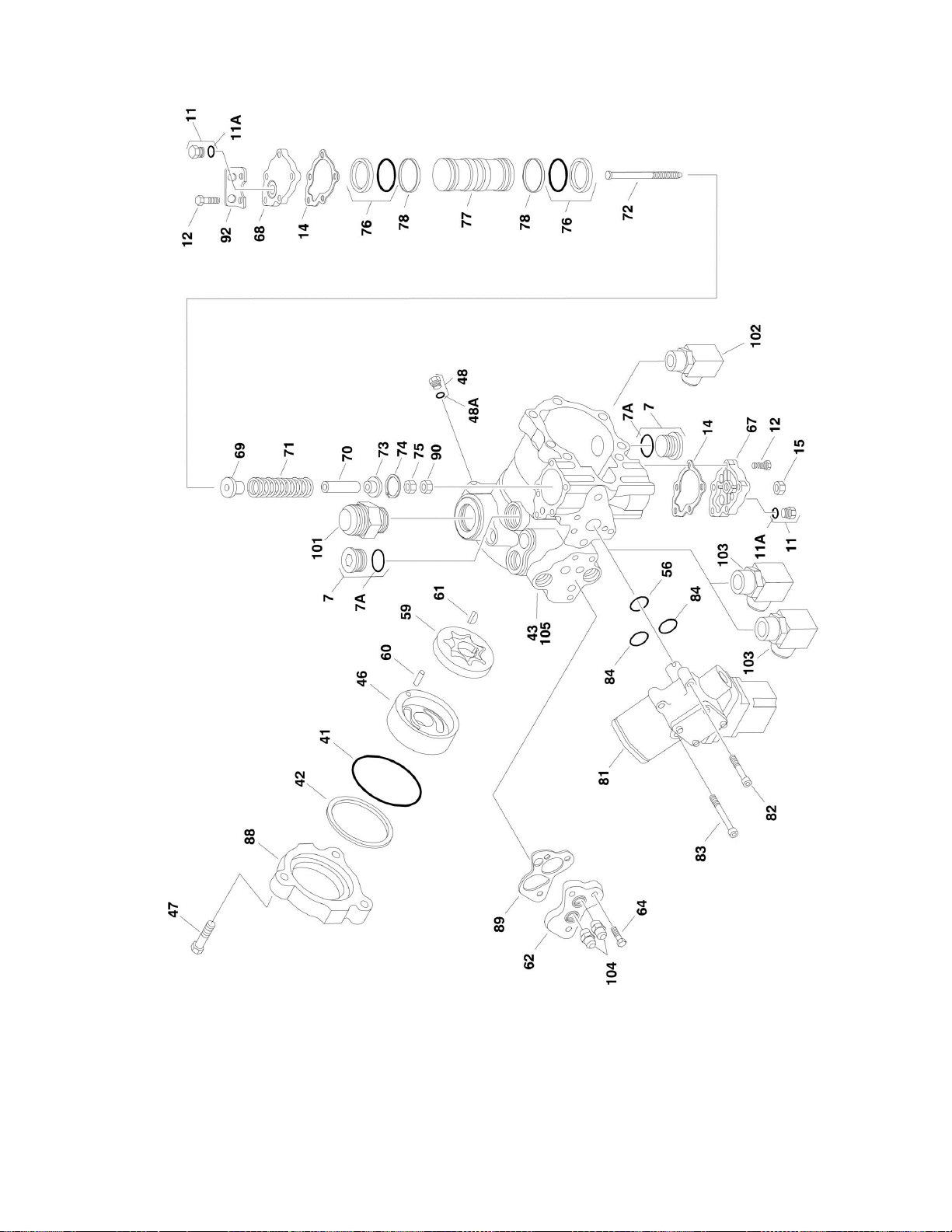
SECTION 2 - TURNTABLE
3121299 660SJ/600S 87
Page 88

ITEM
PART NUMBER
QTY
DESCRIPTION
REV
Ref
PISTON PUMP ASSEMBLY
3600388
Ref
2WD
A 3600381
Ref
4WD
A 1 7007413
1
Shim Kit
2 Ref
Plug Options:
2 7024874
1
Plug (Pump Assembly p/n 3600388) (2WD)
2 7007414
1
Plug (Pump Assembly p/n 3600381) (4WD)
3 7021232
1
O-Ring
4 7021200
1
Spring, Relief Valve
5 7007417
1
Valve, Relief
6 7021232
2
O-Ring
7 7007419
2
Plug 7A
7007418
2
O-Ring
10
7007470
2
Plug 10A
7021256
2
O-Ring
11
7007470
2
Plug 11A
7021256
2
O-Ring
12
7021223
10
Screw
14
7021232
2
Gasket, Servo Cover
15
7007423
1
Nut, Special
18
7007425
1
Bearing, Needle
19
7010116
1
Ring, Retaining
20
7010116
1
Washer
21
7010116
1
Spring
23
7010116
1
Washer
24
7010116
1
Retainer
25
7010116
3
Pin, Slipper Holddown
26
7010116
7
Piston Assembly
27
7010116
1
Retainer, Slipper
28
7010116
1
Guide, Retainer
29
7007435
1
Pin, Spring
30
7021202
1
Screw
31
7007437
1
Bearing, Ball
32
7007438
2
Ring, Retainer
33
7007439
2
Ring 34
7021203
2
Pin, Spring
35
7007441
1
Handle, Pin
36
7007442
1
Sleeve, Bearing
37
7021232
1
Gasket, Front Cover
38
7007444
1
Pin 40
7007446
1
Pin 41
7021232
1
O-Ring
42
7021232
1
Ring, Load Temper
43
7023977
1
Housing, Pump
44
7021232
1
Ring, Back-Up
45
7021232
1
O-Ring
46
7007452
1
Cover, Gerotor
47
7007453
3
Bolt, Hex
48
7007208
1
Plug 48A
7007207
1
O-Ring
SECTION 2 - TURNTABLE
FIGURE 2-11. PISTON PUMP ASSEMBLY
88 660SJ/600S 3121299
Page 89

SECTION 2 - TURNTABLE
ITEM
PART NUMBER
QTY
DESCRIPTION
REV
49 Ref
Cover, Front Options:
49
7024875
1
Cover, Front (Pump Assembly p/n 3600388) (2WD)
49
7007454
1
Cover, Front (Pump Assembly p/n 3600381) (4WD)
50
7010116
1
Block, Cylinder
51
7021207
6
Screw
53
7007457
1
Swashplate
54 Ref
Journal, Bearing Options:
54
7021210
1
Journal, Bearing (Pump Assembly p/n 3600388) (2WD)
54
7021212
1
Journal, Bearing (Pump Assembly p/n 3600381) (4WD)
55
7021232
1
Seal, Lip
56
7021232
1
O-Ring
57
7010121
1
Shaft, Main Pump
58
7021214
1
Plate, Valve
59
7007463
1
Gerotor Assembly
60
7007464
1
Pin 61
7007465
1
Key, Woodruff
62
7007466
1
Adaptor, Remote Filtration
64
7021218
3
Screw
67
7021220
1
Cover, Servo
68
7021219
1
Cover, Servo
69
7023979
1
Guide, Spring
70
7007484
1
Stop, Servo
71
7007485
1
Spring
72
7021221
1
Screw
73
7007487
1
Guide, Spring
74
7007488
1
Ring, Retaining
75
7021222
1
Locknut
76
See Note
2
Ring, Piston (Note: Use Item 200A or 200B)
77
7007494
1
Piston, Servo
78
See Note
2
O-Ring (Note: Use Item 200A or 200B)
79 Ref
Valve, Bypass Options:
79
7024877
Valve, Bypass (Pump Assembly p/n 3600388) (2WD)
79
7007472
Valve, Bypass (Pump Assembly p/n 3600381) (4WD)
80
7010122
2
Valve, Pressure Relief Options (Includes Item 6):
80
7010122
2
Valve (Pump Assembly p/n 3600388) (2WD)
80
7024851
2
Valve (Pump Assembly p/n 3600381) (4WD)
81
7007474
1
Control, Dual Oil-Filled
81
7007496
1
Coil Assembly (Pilot)
81
7007497
1
Plug (Pump)
81
7007498
1
Plug (Valve Harness)
82
7001498
2
Screw
83
7007478
2
Screw
84
7001433
2
O-Ring
86
7007475
1
Plug, Orifice/Screen (.156)
87
7007477
2
Plug, Orifice (.37)
88
7007476
1
Adapter, Auxiliary Pump
89
7021217
1
Spacer/Gasket
90
7021206
1
Nut 91
7024800
2
Spring
92
7021201
1
Bracket, Lifting
Ref
PISTON PUMP AND FITTING ASSEMBLIES
3121299 660SJ/600S 89
Page 90

ITEM
PART NUMBER
QTY
DESCRIPTION
REV
3600394
Ref
2WD
D 1001117799
Ref
4WD
A
101
2220377
1
Fitting, Straight
101
2220479
1
Fitting, Straight
102
2220578
1
Fitting, 90
103
2220646
2
Fitting, 90
104
2220947
2
Fitting, Straight
105
Ref
Pump Options (Includes Items 1 - 92)
105
3600388
1
2WD
105
3600381
1
4WD Ref
KIT OPTIONS:
200
Ref
Seal Kit Options:
200A
7021232
1
Seal Kit - Complete (Includes Items 3, 6, 14, 37, 41, 42, 44, 45,
55, 56, 76, 78, 84 & 89)
200B
7007412
1
Seal Kit - Servo Piston (Includes Items 76 & 78)
201
7010116
1
Cylinder Block Kit (Includes Items 19-28 & 50)
SECTION 2 - TURNTABLE
90 660SJ/600S 3121299
Page 91

Page 92

SECTION 2 - TURNTABLE
FIGURE 2-12. GEAR PUMP ASSEMBLY
92 660SJ/600S 3121299
Page 93

SECTION 2 - TURNTABLE
ITEM
PART NUMBER
QTY
DESCRIPTION
REV
3600242
Ref
GEAR PUMP ASSEMBLY
1 7010105
2
Bearing/Bushing
2
See Note
1
Housing (Note: Not Available - Purchase p/n 3600242 Complete
Replacement.)
3
See Note
1
Flange (Note: Not Available - Purchase p/n 3600242 Complete
Replacement.)
4
7010103
1
Cover 5
7012987
1
Gear, Drive
6 7012988
1
Gear, Idler
7 7007489
2
Ring, Anti-Extrusion
8 7007489
2
Seal 9
See Note
4
Bolt (Note: Not Available for Purchase.)
10
7010104
1
Ring, Retaining
11
See Note
4
Pin, Dowel (Note: Not Available for Purchase.)
12
7007489
2
Seal, O-Ring
13
7007489
1
Seal, Shaft
3600395
Ref
GEAR PUMP AND FITTING ASSEMBLY
A
101
2220376
1
Fitting, Straight
102
2220810
1
Fitting, Reducer
103
3600242
1
Pump (Includes Items 1 - 13)
104
4640744
1
Fitting, Check Valve
Ref
KIT OPTIONS
200
7007489
1
Seal Kit (Includes Items 7, 8, 12 & 13)
FIGURE 2-12. GEAR PUMP ASSEMBLY
3121299 660SJ/600S 93
Page 94

SECTION 2 - TURNTABLE
FIGURE 2-13. TANK INSTALLATIONS
94 660SJ/600S 3121299
Page 95

SECTION 2 - TURNTABLE
ITEM
PART NUMBER
QTY
DESCRIPTION
REV
Ref
TANKS INSTALLATIONS
1001150389
Ref
Deutz Engine Machines
C 1001150388
Ref
GM Engine Machines
B 1 0100011
AR
Compound, Locking
2 0100079
AR
Sealant, Pipe
3 0641608
2
Bolt 3/8in-16NC x 1in
4 0641618
4
Bolt 3/8in-16NC x 2-1/4in
5 0641811
2
Bolt 1/2in-13NC x 1-3/8in
6 2200222
1
Plug (Deutz Engine Machines Only)
7 3311601
AR
Nut 3/8in-16NC
8 4240113
1
Strap, Tank (Deutz Engine Machines Only)
9
4280295
25
in/63cm
Strip, Protective (Deutz Engine Machines Only)
10
4360436
1
Switch, Fuel Level
11 Ref
Tank, Fuel Options:
11
4400400
1
Deutz Engine Machines
11
1001111514
1
GM Engine Machines
11A
Ref
Cap Options:
11A
70002715
1
Standard Black Cap (GM Engine Machines) (Not Shown)
11A
7016314
1
Standard Black Cap (Deutz Engine Machines)
11A
1120487
1
Optional Blue Cap (Deutz Engine Machines) (Not Shown)
(Not Included with Tank)
11B
70002716
1
Adapter
11C
Ref
Tube, Fuel Pick-up (with Fitting) Options:
11C
70004149
1
GM Engine Machines
11C
7019658
1
Deutz Engine Machines
12
1001145172
1
Hydraulic Tank Assembly (See Items 101-110 for Breakdown)
13
4420038
75 in/1.9m
Tape, Rubber
14
4751600
AR
Flatwasher 3/8in Regular
15
4891800
2
Flatwasher 1/2in Hardened
16
1001150198
1
Tray Ref
Note: Items 54 - 75 Used on GM Engine Machines Only
54
4751800
2
Flatwasher 1/2in Regular
59
0641818
2
Bolt 1/2in-13NC x 2-1/4in
62
2221270
1
Fitting, Brass
65
4641022
1
Valve, Needle
66
3576755
1
Cover, Fuel Pump
67
0100020
AR
Sealant
68
0100062
AR
Retaining Compound #680
69
4568119
1
Tube, Fuel
71
3572423
1
Plate, Valve, Needle
72
0641508
AR
Bolt 5/16in-18NC x 1in
73
4711500
AR
Flatwasher 5/16in Thin
74
3311505
AR
Locknut 5/16in-18NC
75
1001118133
2
Bracket
1001145172
Ref
HYDRAULIC TANK ASSEMBLY
F
101
83304173
6
Flatwasher 1/4in Regular
102
7024441
1
Gauge, Sight
103
83304174
6
Nut 1/4in-20NC
104
7024446
1
Plug, Magnetic
FIGURE 2-13. TANK INSTALLATIONS
3121299 660SJ/600S 95
Page 96

ITEM
PART NUMBER
QTY
DESCRIPTION
REV
105
4060803
22
in/68cm
Trim
106
7024444
1
Cap, Vented
107
7024439
1
Cover 108
7024440
1
Gasket
109
7024445
1
Strainer
110
0100079
AR
Sealant #565
1001151010
Ref
LP TANK BRACKETS INSTALLATION (GM ENGINE MACHINES
ONLY)
C
200
Ref
Tank, LP - 43.5 Lbs Options:
200
4400275
1
Aluminum
200
4400420
1
Steel 201
1320220
2
Clamp 201
1320127
2
Clamp, Toggle (1 Per Clamp)
202
2720144
2
Hose
203
0100020
AR
Sealant, Pipe
204
2221197
1
Fitting, Reducer
205
2180125
1
Fitting, 90 Swivel
206
2220261
1
Fitting, Nipple
207
2180388
1
Fitting, Bulkhead
208
2180389
1
Valve, Relief
209
2220418
1
Fitting, Tee
210
2180387
2
Fitting, Straight
211
0641617
8
Bolt 3/8in-16NC x 2-1/8in
212
4891600
16
Flatwasher 3/8in Hardened
213
2180418
2
Fitting, Connector
214
3311605
8
Locknut 3/8in-16NC
215
1320218
2
Clamp, Spring
216
3910808
2
Screw, Round Head #8-32NC x 1/2in
217
4750800
4
Flatwasher #8 Regular
218
3310805
2
Locknut #8-32NC
219
0181949
2
Angle, Support
220
2221024
2
Fitting, Union Ball Check
SECTION 2 - TURNTABLE
96 660SJ/600S 3121299
Page 97

Page 98

SECTION 2 - TURNTABLE
FIGURE 2-14. ROTARY COUPLING INSTALLATION
98 660SJ/600S 3121299
Page 99

SECTION 2 - TURNTABLE
ITEM
PART NUMBER
QTY
DESCRIPTION
REV
Ref
ROTARY COUPLING INSTALLATIONS
1001151303
Ref
2WS
A 1001151304
Ref
4WS
A 1 0100011
AR
Compound, Locking
2 0641612
2
Bolt 3/8in-16NC x 1-1/2in
3 0641811
1
Bolt 1/2in-13NC x 1-3/8in
4 0641820
2
Bolt 1/2in-13NC x 2-1/2in
5 0903056
1
Bracket
6 3271805
2
Locknut 1/2in-13NC
7 4751600
2
Flatwasher 3/8in Regular
8 4751800
5
Flatwasher 1/2in Regular
9 3322201
2
Nut 3/4in-16NC
10 Ref
Coupling, Rotary Options (See Items 101-123 for Breakdown):
10
1001106974
1
2WS
10
1001106975
1
4WS Ref
ROTARY COUPLING ASSEMBLIES
1001106974
Ref
2WS
1001106975
Ref
4WS
101
See Note
1
Body (Note: Not Available - Purchase Complete Rotary Coupling
Assembly.)
102
Ref
Seal Options:
102
70001248
1
2WS
102
70002212
1
4WS
103
See Note
2
O-Ring (Note: Use Item 200A or 200B)
104
See Note
1
Housing (Note: Not Available - Purchase Complete Rotary
Coupling Assembly.)
105
Ref
Seal, Cap
105
70001248
6
2WS
105
70002212
9
4WS
106
Ref
O-Ring
106
70001248
6
2WS
106
70002212
9
4WS
107
Ref
Ring Options:
107
7026503
2
2WS
107
7026511
2
4WS
108
Ref
Ring, Retaining Options:
108
7026504
1
2WS
108
7013189
1
4WS
109
Ref
Plug Options:
109
80934561
2
2WS
109
80934561
4
4WS
110
See Note
1
Lug, Torque (Note: Not Available for Purchase.)
112
7026197
4
Bolt 5/16in-18NC x 1-1/4in
113
See Note
3
O-Ring (Note: Use Item 200A or 200B)
114
See Note
1
O-Ring (Note: Use Item 200A or 200B)
115
See Note
2
Bearing (Note: Use Item 200A or 200B)
116
7024404
1
Block Valve Assembly
117
7026505
1
Plug
118
7026506
1
Valve, Check
119
7026507
1
Plug
FIGURE 2-14. ROTARY COUPLING INSTALLATION
3121299 660SJ/600S 99
Page 100

ITEM
PART NUMBER
QTY
DESCRIPTION
REV
120
See Note
1
Plunger, Valve (Note: Not Available - Purchase p/n 7024404)
121
7026509
1
Spring, Compression
122
See Note
AR
Protective Netting (Not Shown) (1660303, 1660304, 1001106974
& 1001106975 Couplings) (Note: Not Available for Purchase.)
123
Ref
Seal Options:
123
70001248
1
2WS
123
70002212
1
4WS
124
See Note
4
Screw, Socket Head #10-24NC x 1/2in (Note: Not Available Purchase Locally.)
125
See Note
2
Locknut #10-24NC (Note: Not Available - Purchase Locally.)
126
See Note
4
Flatwasher #10 Regular (Note: Not Available - Purchase Locally.)
127
70003454
1
Bracket, Switch Mounting
128
4360517
1
Switch, Proximity
Ref
KIT OPTIONS
200
Ref
Seal Kit Options:
200A
70001248
1
1001106974 Couplings (Includes Items 102, 103, 105, 106, 113,
114, 115 & 123)
200B
70002212
1
1001106975 Coupling (Includes Items 102, 103, 105, 106, 113,
114, 115 & 123)
SECTION 2 - TURNTABLE
100 660SJ/600S 3121299
 Loading...