

Page 1
Service and Maintenance Manual
Models
600S/SJ
660SJ
600A/AJ
Prior to
S/N 0300080000
P/N - 3120840
November 22, 2016
Page 2

Page 3
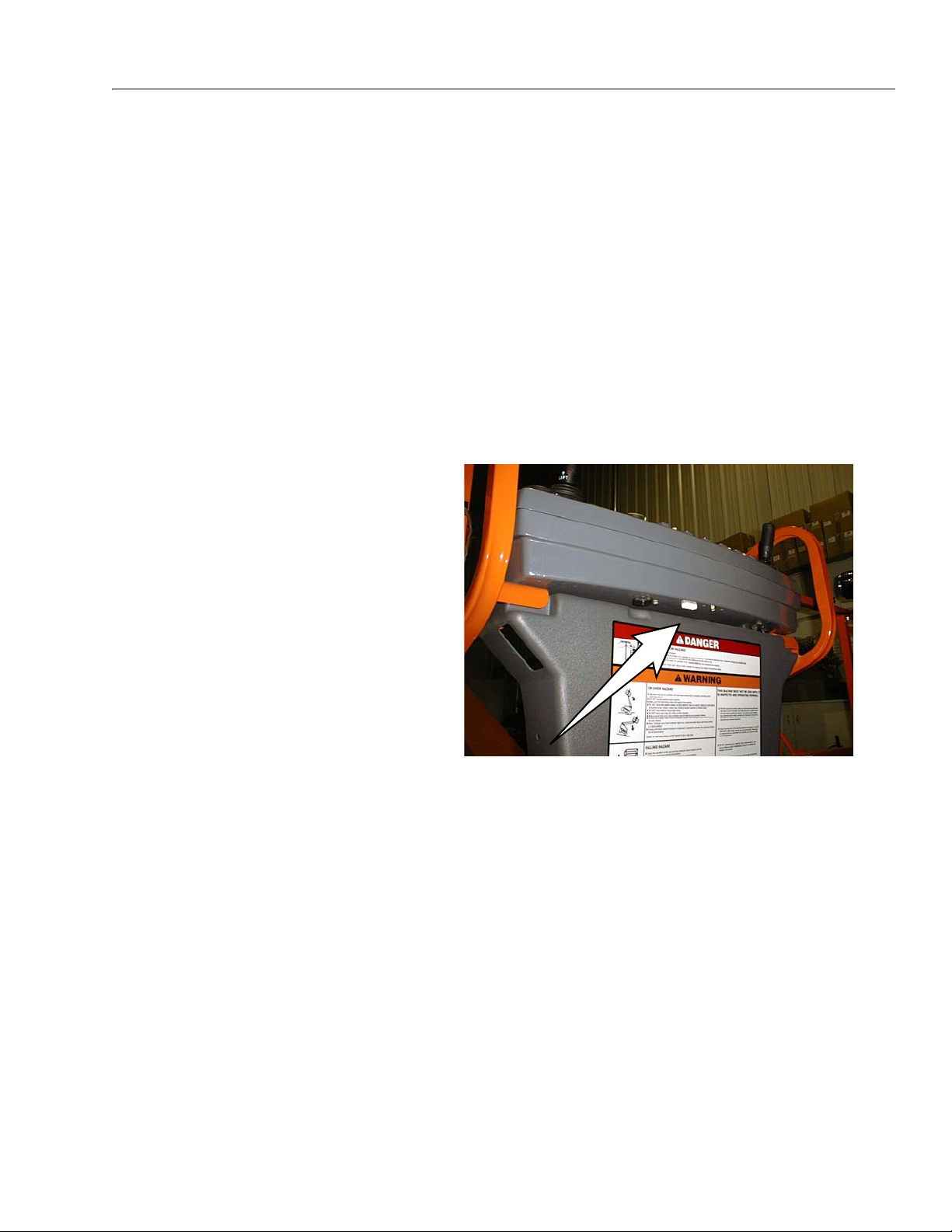
A Machine that incorporates
ADE (JLG Control System) can
be outwardly identified by the
analyzer connection at the base
of the platform control box as
shown by the arrow.
ADE Identification
All 600S, 600SJ, and 660SJ machines from S/N 61927 incorporate ADE (JLG Control System). The following machine serial numbers prior to S/N 61927 also utilize EPBCS: 58993,
58998, 59222, 59223, 59275, 59281, 59315, 59319, 59352, 59358, 59631, 59769, 60253,
60254, 60286, 60642, 60645, 61120, 61257, 61402, 61440, 61491, 61833, 61840, 61875, and
61878.
All 600A and 600AJ machines from S/N 64249 incorporate ADE (JLG Control System). The
following machine serial numbers prior to S/N 64249 also utilize EPBCS: 63908, 63912,
63932, 63936, 63938, 63954, 63959, and 63963.
– JLG Lift –
Page 4

This page left blank intentionally.
– JLG Lift –
Page 5
INTRODUCTION
SECTION A. INTRODUCTION - MAINTENANCE SAFETY
PRECAUTIONS
AGENERAL
This section contains the general safety precautions
which must be observed during maintenance of the
aerial platform. It is of utmost importance that maintenance personnel pay strict attention to these warnings and precautions to avoid possible injury to
themselves or others, or damage to the equipment.
A maintenance program must be followed to ensure
that the machine is safe to operate.
MODIFICATION OF THE MACHINE WITHOUT CERTIFICATION BY A
RESPONSIBLE AUTHORITY THAT THE MACHINE IS AT LEAST AS
SAFE AS ORIGINALLY MANUFACTURED, IS A SAFETY VIOLATION.
The specific precautions to be observed during
maintenance are inserted at the appropriate point in
the manual. These precautions are, for the most
part, those that apply when servicing hydraulic and
larger machine component parts.
Your safety, and that of others, is the first consideration when engaging in the maintenance of equipment. Always be conscious of weight. Never attempt
to move heavy parts without the aid of a mechanical
device. Do not allow heavy objects to rest in an
unstable position. When raising a portion of the
equipment, ensure that adequate support is provided.
reservoir. Pressure feed lines to system components
can then be disconnected with minimal fluid loss.
CMAINTENANCE
FAILURE TO COMPLY WITH SAFETY PRECAUTIONS LISTED IN
THIS SECTION MAY RESULT IN MACHINE DAMAGE, PERSONNEL
INJURY OR DEATH AND IS A SAFETY VIOLATION.
• ENSURE REPLACEMENT PARTS OR COMPONENTS
ARE IDENTICAL OR EQUIVALENT TO ORIGINAL PARTS
OR COMPONENTS.
• NO SMOKING IS MANDA T OR Y. NEVER REFUEL DURING ELECTRICAL STORMS. ENSURE THAT FUEL
CAP IS CLOSED AND SECURE AT ALL OTHER
TIMES.
• REMOVE ALL RINGS, WATCHES AND JEWELRY
WHEN PERFORMING ANY MAINTENANCE.
• DO NOT WEAR LONG HAIR UNRESTRAINED, OR
LOOSE-FITTING CLOTHING AND NECKTIES WHICH
ARE APT TO BECOME CAUGHT ON OR ENTANGLED
IN EQUIPMENT.
• OBSERVE AND OBEY ALL WARNINGS AND CAUTIONS ON MACHINE AND IN SERVICEMANUAL.
• KEEP OIL, GREASE, WATER, ETC. WIPED FROM
STANDING SURFACES AND HAND HOLDS.
• USE CAUTION WHEN CHECKING A HOT, PRESSURIZED COOLANT SYSTEM.
• NEVER WORK UNDER AN ELEVATED BOOM UNTIL
SINCE THE MACHINE MANUFACTURER HAS NO DIRECT CONTROL OVER THE FIELD INSPECTION AND MAINTENANCE, SAFETY
IN THIS AREA RESPONSIBILITY OF THE OWNER/OPERATOR.
B HYDRAULIC SYSTEM SAFETY
It should be noted that the machines hydraulic systems operate at extremely high potentially dangerous pressures. Every effort should be made to
relieve any system pressure prior to disconnecting
or removing any portion of the system.
Relieve system pressure by cycling the applicable
control several times with the engine stopped and
BOOM HAS BEEN SAFELY RESTRAINED FROM ANY
MOVEMENT BY BLOCKING OR OVERHEAD SLING,
OR BOOM SAFETY PROP HAS BEEN ENGAGED.
• BEFORE MAKING ADJUSTMENTS, LUBRICATING OR
PERFORMING ANY OTHER MAINTENANCE, SHUT
OFF ALL POWER CONTROLS.
• BATTERY SHOULD ALWAYS BE DISCONNECTEDDURING REPLACEMENT OF ELECTRICAL COMPONENTS.
• KEEP ALL SUPPORT EQUIPMENT AND ATTACHMENTS STOWED IN THEIR PROPER PLACE.
• USE ONL Y APPROVED, NONFLAMMABLE CLEANING
SOLVENTS.
ignition on, to direct any line pressure back into the
3120840 – JLG Lift – A-1
Page 6

INTRODUCTION
REVISON LOG
Original Issue September, 1996
Revised April 1, 1999
Revised August 4, 2000
Revised November 15, 2000
Revised February 6, 2001
Revised August 29, 2001
Revised June 13, 2002
Revised March 21, 2003
Revised January 28, 2004
Revised September 26, 2005
Revised November 22, 2016
A-2 – JLG Lift – 3120840
Page 7

TABLE OF CONTENTS
TABLE OF CONTENTS
SUBJECT - SECTION, PARAGRAPH PAGE NO.
SECTION A - INTRODUCTION - MAINTENANCE SAFETY PRECAUTIONS
A General . . . . . . . . . . . . . . . . . . . . . . . . . . . . . . . . . . . . . . . . . . . . . . . . . . . . . . . . . . . . . . . . . . . . . .A-1
B Hydraulic System Safety . . . . . . . . . . . . . . . . . . . . . . . . . . . . . . . . . . . . . . . . . . . . . . . . . . . . . . . . .A-1
C Maintenance . . . . . . . . . . . . . . . . . . . . . . . . . . . . . . . . . . . . . . . . . . . . . . . . . . . . . . . . . . . . . . . . . .A-1
SECTION 1 - SPECIFICATIONS
1.1 Capacities . . . . . . . . . . . . . . . . . . . . . . . . . . . . . . . . . . . . . . . . . . . . . . . . . . . . . . . . . . . . . . . . . . . . 1-1
Fuel Tank . . . . . . . . . . . . . . . . . . . . . . . . . . . . . . . . . . . . . . . . . . . . . . . . . . . . . . . . . . . . . . . . 1-1
Hydraulic Oil Tank . . . . . . . . . . . . . . . . . . . . . . . . . . . . . . . . . . . . . . . . . . . . . . . . . . . . . . . . . 1-1
Hydraulic System (Including Tank) . . . . . . . . . . . . . . . . . . . . . . . . . . . . . . . . . . . . . . . . . . . . 1-1
Torque Hub, Drive . . . . . . . . . . . . . . . . . . . . . . . . . . . . . . . . . . . . . . . . . . . . . . . . . . . . . . . . . 1-1
Engine Crankcase . . . . . . . . . . . . . . . . . . . . . . . . . . . . . . . . . . . . . . . . . . . . . . . . . . . . . . . . . 1-1
1.2 Component Data . . . . . . . . . . . . . . . . . . . . . . . . . . . . . . . . . . . . . . . . . . . . . . . . . . . . . . . . . . . . . . .1-1
Engine - Diesel (Liquid-Cooled) . . . . . . . . . . . . . . . . . . . . . . . . . . . . . . . . . . . . . . . . . . . . . . 1-1
Engine - Diesel (Water-Cooled). . . . . . . . . . . . . . . . . . . . . . . . . . . . . . . . . . . . . . . . . . . . . . . 1-1
Drive System (S Models) . . . . . . . . . . . . . . . . . . . . . . . . . . . . . . . . . . . . . . . . . . . . . . . . . . . . 1-1
Drive System (A Models) . . . . . . . . . . . . . . . . . . . . . . . . . . . . . . . . . . . . . . . . . . . . . . . . . . . . 1-1
Steer System (S Models). . . . . . . . . . . . . . . . . . . . . . . . . . . . . . . . . . . . . . . . . . . . . . . . . . . . 1-2
Steer System (A Models). . . . . . . . . . . . . . . . . . . . . . . . . . . . . . . . . . . . . . . . . . . . . . . . . . . . 1-2
Swing System . . . . . . . . . . . . . . . . . . . . . . . . . . . . . . . . . . . . . . . . . . . . . . . . . . . . . . . . . . . . 1-2
1.3 Performance Data . . . . . . . . . . . . . . . . . . . . . . . . . . . . . . . . . . . . . . . . . . . . . . . . . . . . . . . . . . . . . .1-2
Turning Radius (Outside) (S Models) . . . . . . . . . . . . . . . . . . . . . . . . . . . . . . . . . . . . . . . . . . 1-2
Turning Radius (Outside) (A Models) . . . . . . . . . . . . . . . . . . . . . . . . . . . . . . . . . . . . . . . . . . 1-2
Turning Radius (Inside) (S Models). . . . . . . . . . . . . . . . . . . . . . . . . . . . . . . . . . . . . . . . . . . . 1-2
Turning Radius (Inside) (A Models). . . . . . . . . . . . . . . . . . . . . . . . . . . . . . . . . . . . . . . . . . . . 1-2
Boom Elevation (S Models). . . . . . . . . . . . . . . . . . . . . . . . . . . . . . . . . . . . . . . . . . . . . . . . . . 1-3
Boom Elevation (A Models) . . . . . . . . . . . . . . . . . . . . . . . . . . . . . . . . . . . . . . . . . . . . . . . . . . 1-3
Machine Weight approximately . . . . . . . . . . . . . . . . . . . . . . . . . . . . . . . . . . . . . . . . . . . . . . . 1-3
Machine Height (Stowed) (S Models) . . . . . . . . . . . . . . . . . . . . . . . . . . . . . . . . . . . . . . . . . . 1-3
Machine Height (Stowed) (A Models) . . . . . . . . . . . . . . . . . . . . . . . . . . . . . . . . . . . . . . . . . . 1-3
Machine Length (Stowed) (S Models). . . . . . . . . . . . . . . . . . . . . . . . . . . . . . . . . . . . . . . . . . 1-3
Machine Length (Stowed) (A Models). . . . . . . . . . . . . . . . . . . . . . . . . . . . . . . . . . . . . . . . . . 1-3
Machine Width (S Models) . . . . . . . . . . . . . . . . . . . . . . . . . . . . . . . . . . . . . . . . . . . . . . . . . . 1-3
Machine Width (A Models) . . . . . . . . . . . . . . . . . . . . . . . . . . . . . . . . . . . . . . . . . . . . . . . . . . 1-3
Wheel base (S Models) . . . . . . . . . . . . . . . . . . . . . . . . . . . . . . . . . . . . . . . . . . . . . . . . . . . . . 1-3
Wheel base (A Models) . . . . . . . . . . . . . . . . . . . . . . . . . . . . . . . . . . . . . . . . . . . . . . . . . . . . . 1-3
1.4 Function Speeds . . . . . . . . . . . . . . . . . . . . . . . . . . . . . . . . . . . . . . . . . . . . . . . . . . . . . . . . . . . . . . .1-3
Machine Orientation When Doing Speed Tests . . . . . . . . . . . . . . . . . . . . . . . . . . . . . . . . . . 1-3
Test Notes . . . . . . . . . . . . . . . . . . . . . . . . . . . . . . . . . . . . . . . . . . . . . . . . . . . . . . . . . . . . . . . 1-4
1.5 Torque Requirements . . . . . . . . . . . . . . . . . . . . . . . . . . . . . . . . . . . . . . . . . . . . . . . . . . . . . . . . . . . 1-4
1.6 Lubrication. . . . . . . . . . . . . . . . . . . . . . . . . . . . . . . . . . . . . . . . . . . . . . . . . . . . . . . . . . . . . . . . . . . . 1-5
Deutz F4M1011F Engine . . . . . . . . . . . . . . . . . . . . . . . . . . . . . . . . . . . . . . . . . . . . . . . . . . . . 1-5
Continental TMD27 Engine . . . . . . . . . . . . . . . . . . . . . . . . . . . . . . . . . . . . . . . . . . . . . . . . . . 1-5
Hydraulic Oil . . . . . . . . . . . . . . . . . . . . . . . . . . . . . . . . . . . . . . . . . . . . . . . . . . . . . . . . . . . . . 1-5
Lubrication Specifications . . . . . . . . . . . . . . . . . . . . . . . . . . . . . . . . . . . . . . . . . . . . . . . . . . . 1-6
1.7 Pressure Settings . . . . . . . . . . . . . . . . . . . . . . . . . . . . . . . . . . . . . . . . . . . . . . . . . . . . . . . . . . . . . .1-6
Rexroth Valve (S Models) . . . . . . . . . . . . . . . . . . . . . . . . . . . . . . . . . . . . . . . . . . . . . . . . . . . 1-6
Rexroth Valve (A Models) . . . . . . . . . . . . . . . . . . . . . . . . . . . . . . . . . . . . . . . . . . . . . . . . . . . 1-6
1.8 Cylinder Specifications . . . . . . . . . . . . . . . . . . . . . . . . . . . . . . . . . . . . . . . . . . . . . . . . . . . . . . . . . .1-7
1.9 Major Component Weights . . . . . . . . . . . . . . . . . . . . . . . . . . . . . . . . . . . . . . . . . . . . . . . . . . . . . . .1-8
1.10 Critical Stability Weights . . . . . . . . . . . . . . . . . . . . . . . . . . . . . . . . . . . . . . . . . . . . . . . . . . . . . . . . .1-9
1.11 Serial Number Locations. . . . . . . . . . . . . . . . . . . . . . . . . . . . . . . . . . . . . . . . . . . . . . . . . . . . . . . . .1-14
3120840 – JLG Lift – i
Page 8

TABLE OF CONTENTS (Continued)
TABLE OF CONTENTS (continued)
SUBJECT - SECTION, PARAGRAPH PAGE NO.
SECTION 2 - GENERAL
2.1 Machine Preparation, Inspection, and Maintenance . . . . . . . . . . . . . . . . . . . . . . . . . . . . . . . . . . .2-1
General . . . . . . . . . . . . . . . . . . . . . . . . . . . . . . . . . . . . . . . . . . . . . . . . . . . . . . . . . . . . . . . . . 2-1
Preparation, Inspection, and Maintenance . . . . . . . . . . . . . . . . . . . . . . . . . . . . . . . . . . . . . . 2-1
Pre-Start Inspection . . . . . . . . . . . . . . . . . . . . . . . . . . . . . . . . . . . . . . . . . . . . . . . . . . . . . . . . 2-1
Pre-Delivery Inspection and Frequent Inspection . . . . . . . . . . . . . . . . . . . . . . . . . . . . . . . . . 2-1
Annual Machine Inspection . . . . . . . . . . . . . . . . . . . . . . . . . . . . . . . . . . . . . . . . . . . . . . . . . . 2-1
Preventative Maintenance . . . . . . . . . . . . . . . . . . . . . . . . . . . . . . . . . . . . . . . . . . . . . . . . . . . 2-1
2.2 Service and Guidelines . . . . . . . . . . . . . . . . . . . . . . . . . . . . . . . . . . . . . . . . . . . . . . . . . . . . . . . . . .2-2
General . . . . . . . . . . . . . . . . . . . . . . . . . . . . . . . . . . . . . . . . . . . . . . . . . . . . . . . . . . . . . . . . . 2-2
Safety and Workmanship . . . . . . . . . . . . . . . . . . . . . . . . . . . . . . . . . . . . . . . . . . . . . . . . . . . 2-2
Cleanliness. . . . . . . . . . . . . . . . . . . . . . . . . . . . . . . . . . . . . . . . . . . . . . . . . . . . . . . . . . . . . . . 2-2
Components Removal and Installation . . . . . . . . . . . . . . . . . . . . . . . . . . . . . . . . . . . . . . . . . 2-2
Component Disassembly and Reassembly . . . . . . . . . . . . . . . . . . . . . . . . . . . . . . . . . . . . . 2-3
Pressure-Fit Parts . . . . . . . . . . . . . . . . . . . . . . . . . . . . . . . . . . . . . . . . . . . . . . . . . . . . . . . . . 2-3
Bearings. . . . . . . . . . . . . . . . . . . . . . . . . . . . . . . . . . . . . . . . . . . . . . . . . . . . . . . . . . . . . . . . . 2-3
Gaskets . . . . . . . . . . . . . . . . . . . . . . . . . . . . . . . . . . . . . . . . . . . . . . . . . . . . . . . . . . . . . . . . . 2-3
Bolt Usage and Torque Application . . . . . . . . . . . . . . . . . . . . . . . . . . . . . . . . . . . . . . . . . . . 2-3
Hydraulic Lines and Electrical Wiring . . . . . . . . . . . . . . . . . . . . . . . . . . . . . . . . . . . . . . . . . . 2-3
Hydraulic System. . . . . . . . . . . . . . . . . . . . . . . . . . . . . . . . . . . . . . . . . . . . . . . . . . . . . . . . . . 2-3
Lubrication . . . . . . . . . . . . . . . . . . . . . . . . . . . . . . . . . . . . . . . . . . . . . . . . . . . . . . . . . . . . . . . 2-3
Battery . . . . . . . . . . . . . . . . . . . . . . . . . . . . . . . . . . . . . . . . . . . . . . . . . . . . . . . . . . . . . . . . . . 2-3
Lubrication and Servicing . . . . . . . . . . . . . . . . . . . . . . . . . . . . . . . . . . . . . . . . . . . . . . . . . . . 2-3
2.3 Lubrication and Information . . . . . . . . . . . . . . . . . . . . . . . . . . . . . . . . . . . . . . . . . . . . . . . . . . . . . .2-4
Hydraulic System. . . . . . . . . . . . . . . . . . . . . . . . . . . . . . . . . . . . . . . . . . . . . . . . . . . . . . . . . . 2-4
Hydraulic Oil . . . . . . . . . . . . . . . . . . . . . . . . . . . . . . . . . . . . . . . . . . . . . . . . . . . . . . . . . . . . . 2-4
Changing Hydraulic Oil . . . . . . . . . . . . . . . . . . . . . . . . . . . . . . . . . . . . . . . . . . . . . . . . . . . . . 2-4
Lubrication Specifications . . . . . . . . . . . . . . . . . . . . . . . . . . . . . . . . . . . . . . . . . . . . . . . . . . . 2-4
2.4 Cylinder Drift Test . . . . . . . . . . . . . . . . . . . . . . . . . . . . . . . . . . . . . . . . . . . . . . . . . . . . . . . . . . . . . . 2-5
Platform Drift . . . . . . . . . . . . . . . . . . . . . . . . . . . . . . . . . . . . . . . . . . . . . . . . . . . . . . . . . . . . . 2-5
Cylinder Drift . . . . . . . . . . . . . . . . . . . . . . . . . . . . . . . . . . . . . . . . . . . . . . . . . . . . . . . . . . . . . 2-5
2.5 Pins and Composite Bearing Repair Guidelines . . . . . . . . . . . . . . . . . . . . . . . . . . . . . . . . . . . . . .2-5
2.6 Welding on JLG Equipment . . . . . . . . . . . . . . . . . . . . . . . . . . . . . . . . . . . . . . . . . . . . . . . . . . . . . .2-6
Do the Following When Welding on JLG Equipment . . . . . . . . . . . . . . . . . . . . . . . . . . . . . . 2-6
Do NOT Do the Following When Welding on JLG Equipment . . . . . . . . . . . . . . . . . . . . . . . 2-6
2.7 Applying Silicone Dielectric Compound to Electrical Connections . . . . . . . . . . . . . . . . . . . . . . . .2-6
2.8 AMP Connector . . . . . . . . . . . . . . . . . . . . . . . . . . . . . . . . . . . . . . . . . . . . . . . . . . . . . . . . . . . . . . . .2-7
Applying Silicone Dielectric Compound to AMP Connectors. . . . . . . . . . . . . . . . . . . . . . . . 2-7
Assembly . . . . . . . . . . . . . . . . . . . . . . . . . . . . . . . . . . . . . . . . . . . . . . . . . . . . . . . . . . . . . . . . 2-7
Disassembly. . . . . . . . . . . . . . . . . . . . . . . . . . . . . . . . . . . . . . . . . . . . . . . . . . . . . . . . . . . . . . 2-9
Wedge Lock. . . . . . . . . . . . . . . . . . . . . . . . . . . . . . . . . . . . . . . . . . . . . . . . . . . . . . . . . . . . . . 2-9
Service - Voltage Reading . . . . . . . . . . . . . . . . . . . . . . . . . . . . . . . . . . . . . . . . . . . . . . . . . . . 2-9
2.9 Deutsch Connectors . . . . . . . . . . . . . . . . . . . . . . . . . . . . . . . . . . . . . . . . . . . . . . . . . . . . . . . . . . . .2-11
DT/DTP Series Assembly. . . . . . . . . . . . . . . . . . . . . . . . . . . . . . . . . . . . . . . . . . . . . . . . . . . . 2-11
DT/DTP Series Disassembly . . . . . . . . . . . . . . . . . . . . . . . . . . . . . . . . . . . . . . . . . . . . . . . . . 2-11
HD30/HDP20 Series Assembly . . . . . . . . . . . . . . . . . . . . . . . . . . . . . . . . . . . . . . . . . . . . . . . 2-12
HD30/HDP20 Series Disassembly. . . . . . . . . . . . . . . . . . . . . . . . . . . . . . . . . . . . . . . . . . . . . 2-12
ii – JLG Lift – 3120840
Page 9

TABLE OF CONTENTS
TABLE OF CONTENTS (continued)
SUBJECT - SECTION, PARAGRAPH PAGE NO.
SECTION 3 - CHASSIS & TURNTABLE
3.1 Drive Torque hub, Prior to S/N 75606 . . . . . . . . . . . . . . . . . . . . . . . . . . . . . . . . . . . . . . . . . . . . . .3-1
Disassembly. . . . . . . . . . . . . . . . . . . . . . . . . . . . . . . . . . . . . . . . . . . . . . . . . . . . . . . . . . . . . . 3-1
Cleaning and Inspection . . . . . . . . . . . . . . . . . . . . . . . . . . . . . . . . . . . . . . . . . . . . . . . . . . . . 3-1
Repair. . . . . . . . . . . . . . . . . . . . . . . . . . . . . . . . . . . . . . . . . . . . . . . . . . . . . . . . . . . . . . . . . . . 3-3
Assembly . . . . . . . . . . . . . . . . . . . . . . . . . . . . . . . . . . . . . . . . . . . . . . . . . . . . . . . . . . . . . . . . 3-5
3.2 Torque Hub, Drive (Auburn Gear). . . . . . . . . . . . . . . . . . . . . . . . . . . . . . . . . . . . . . . . . . . . . . . . . .3-9
Disassembly. . . . . . . . . . . . . . . . . . . . . . . . . . . . . . . . . . . . . . . . . . . . . . . . . . . . . . . . . . . . . . 3-9
Assembly . . . . . . . . . . . . . . . . . . . . . . . . . . . . . . . . . . . . . . . . . . . . . . . . . . . . . . . . . . . . . . . . 3-9
3.3 Drive Torque hub, S/N 75606 to Present . . . . . . . . . . . . . . . . . . . . . . . . . . . . . . . . . . . . . . . . . . . .3-12
Roll, Leak and Brake Testing. . . . . . . . . . . . . . . . . . . . . . . . . . . . . . . . . . . . . . . . . . . . . . . . . 3-12
Tightening and Torquing Bolts . . . . . . . . . . . . . . . . . . . . . . . . . . . . . . . . . . . . . . . . . . . . . . . 3-12
Main Disassembly . . . . . . . . . . . . . . . . . . . . . . . . . . . . . . . . . . . . . . . . . . . . . . . . . . . . . . . . . 3-13
Input Carrier Disassembly . . . . . . . . . . . . . . . . . . . . . . . . . . . . . . . . . . . . . . . . . . . . . . . . . . . 3-16
Hub-Spindle Disassembly . . . . . . . . . . . . . . . . . . . . . . . . . . . . . . . . . . . . . . . . . . . . . . . . . . . 3-17
Spindle-Brake Disassembly. . . . . . . . . . . . . . . . . . . . . . . . . . . . . . . . . . . . . . . . . . . . . . . . . . 3-18
Cover Disassembly . . . . . . . . . . . . . . . . . . . . . . . . . . . . . . . . . . . . . . . . . . . . . . . . . . . . . . . . 3-20
Input Carrier Sub-Assembly . . . . . . . . . . . . . . . . . . . . . . . . . . . . . . . . . . . . . . . . . . . . . . . . . 3-21
Output Planet Gear Sub-Assembly . . . . . . . . . . . . . . . . . . . . . . . . . . . . . . . . . . . . . . . . . . . . 3-21
Spindle - Brake Sub-Assembly . . . . . . . . . . . . . . . . . . . . . . . . . . . . . . . . . . . . . . . . . . . . . . . 3-21
Hub-Spindle Sub-Assembly . . . . . . . . . . . . . . . . . . . . . . . . . . . . . . . . . . . . . . . . . . . . . . . . . 3-22
Cover Sub-Assembly . . . . . . . . . . . . . . . . . . . . . . . . . . . . . . . . . . . . . . . . . . . . . . . . . . . . . . . 3-23
Main Assembly. . . . . . . . . . . . . . . . . . . . . . . . . . . . . . . . . . . . . . . . . . . . . . . . . . . . . . . . . . . . 3-23
Integral Brake Check . . . . . . . . . . . . . . . . . . . . . . . . . . . . . . . . . . . . . . . . . . . . . . . . . . . . . . . 3-23
3.4 Drive Brake - Mico . . . . . . . . . . . . . . . . . . . . . . . . . . . . . . . . . . . . . . . . . . . . . . . . . . . . . . . . . . . . . .3-27
Disassembly. . . . . . . . . . . . . . . . . . . . . . . . . . . . . . . . . . . . . . . . . . . . . . . . . . . . . . . . . . . . . . 3-27
Inspection . . . . . . . . . . . . . . . . . . . . . . . . . . . . . . . . . . . . . . . . . . . . . . . . . . . . . . . . . . . . . . . 3-27
Assembly . . . . . . . . . . . . . . . . . . . . . . . . . . . . . . . . . . . . . . . . . . . . . . . . . . . . . . . . . . . . . . . . 3-27
3.5 Free Wheeling Option . . . . . . . . . . . . . . . . . . . . . . . . . . . . . . . . . . . . . . . . . . . . . . . . . . . . . . . . . . .3-29
To Disengage Drive Motors and Brakes (Free Wheel) for Towing, etc. . . . . . . . . . . . . . . . . 3-29
To Engage Drive Motors and Brakes (Normal Operation) . . . . . . . . . . . . . . . . . . . . . . . . . . 3-29
3.6 Drive Motor (600S, 600A 4WD) . . . . . . . . . . . . . . . . . . . . . . . . . . . . . . . . . . . . . . . . . . . . . . . . . . . .3-30
Spare Parts Kits . . . . . . . . . . . . . . . . . . . . . . . . . . . . . . . . . . . . . . . . . . . . . . . . . . . . . . . . . . . 3-30
Replacing the Drive Shaft Seal . . . . . . . . . . . . . . . . . . . . . . . . . . . . . . . . . . . . . . . . . . . . . . . 3-31
Disassembly and Assembly . . . . . . . . . . . . . . . . . . . . . . . . . . . . . . . . . . . . . . . . . . . . . . . . . 3-32
Assembly Notes. . . . . . . . . . . . . . . . . . . . . . . . . . . . . . . . . . . . . . . . . . . . . . . . . . . . . . . . . . . 3-36
Taper Roller Bearing Initial Tension . . . . . . . . . . . . . . . . . . . . . . . . . . . . . . . . . . . . . . . . . . . 3-36
Testing and Setup . . . . . . . . . . . . . . . . . . . . . . . . . . . . . . . . . . . . . . . . . . . . . . . . . . . . . . . . . 3-38
3.7 Drive Motor Adjustment Procedure (S Models Only) . . . . . . . . . . . . . . . . . . . . . . . . . . . . . . . . . . .3-38
3.8 Oscillating Axle Bleeding Procedure and Lockout Test . . . . . . . . . . . . . . . . . . . . . . . . . . . . . . . . .3-39
Lockout Cylinder Bleeding . . . . . . . . . . . . . . . . . . . . . . . . . . . . . . . . . . . . . . . . . . . . . . . . . . 3-39
Oscillating Axle Lockout Test . . . . . . . . . . . . . . . . . . . . . . . . . . . . . . . . . . . . . . . . . . . . . . . . 3-40
3.9 Steer Adjustments (S Models) . . . . . . . . . . . . . . . . . . . . . . . . . . . . . . . . . . . . . . . . . . . . . . . . . . . .3-41
3.10 Swing Hub . . . . . . . . . . . . . . . . . . . . . . . . . . . . . . . . . . . . . . . . . . . . . . . . . . . . . . . . . . . . . . . . . . . .3-41
Adjustment Procedures . . . . . . . . . . . . . . . . . . . . . . . . . . . . . . . . . . . . . . . . . . . . . . . . . . . . . 3-41
3.11 Swing Bearing . . . . . . . . . . . . . . . . . . . . . . . . . . . . . . . . . . . . . . . . . . . . . . . . . . . . . . . . . . . . . . . . .3-42
Turntable Bearing Mounting Bolt Condition Check . . . . . . . . . . . . . . . . . . . . . . . . . . . . . . . 3-42
Wear Tolerance.(S & A Models) . . . . . . . . . . . . . . . . . . . . . . . . . . . . . . . . . . . . . . . . . . . . . . 3-43
Swing Bearing Replacement . . . . . . . . . . . . . . . . . . . . . . . . . . . . . . . . . . . . . . . . . . . . . . . . . 3-46
Swing Bearing Torque Values . . . . . . . . . . . . . . . . . . . . . . . . . . . . . . . . . . . . . . . . . . . . . . . . 3-47
3120840 – JLG Lift – iii
Page 10

TABLE OF CONTENTS (Continued)
TABLE OF CONTENTS (continued)
SUBJECT - SECTION, PARAGRAPH PAGE NO.
3.12 Swing Brake - Mico . . . . . . . . . . . . . . . . . . . . . . . . . . . . . . . . . . . . . . . . . . . . . . . . . . . . . . . . . . . . .3-47
Disassembly. . . . . . . . . . . . . . . . . . . . . . . . . . . . . . . . . . . . . . . . . . . . . . . . . . . . . . . . . . . . . . 3-47
Inspection . . . . . . . . . . . . . . . . . . . . . . . . . . . . . . . . . . . . . . . . . . . . . . . . . . . . . . . . . . . . . . . 3-49
Assembly . . . . . . . . . . . . . . . . . . . . . . . . . . . . . . . . . . . . . . . . . . . . . . . . . . . . . . . . . . . . . . . . 3-49
3.13 Tilt Alarm Switch (Machines w/ External Tilt . . . . . . . . . . . . . . . . . . . . . . . . . . . . . . . . . . . . . . . . . .3-49
Manual Adjustment . . . . . . . . . . . . . . . . . . . . . . . . . . . . . . . . . . . . . . . . . . . . . . . . . . . . . . . . 3-49
3.14 Spark Arrester Cleaning Instructions . . . . . . . . . . . . . . . . . . . . . . . . . . . . . . . . . . . . . . . . . . . . . . .3-50
3.15 Throttle Checks and Adjustments - Deutz Engine . . . . . . . . . . . . . . . . . . . . . . . . . . . . . . . . . . . . .3-50
General . . . . . . . . . . . . . . . . . . . . . . . . . . . . . . . . . . . . . . . . . . . . . . . . . . . . . . . . . . . . . . . . . 3-50
Procedure . . . . . . . . . . . . . . . . . . . . . . . . . . . . . . . . . . . . . . . . . . . . . . . . . . . . . . . . . . . . . . . 3-50
3.16 Throttle Checks and Adjustments - TMD 27 Continental Engine. . . . . . . . . . . . . . . . . . . . . . . . . . 3-50
SECTION 4 - BOOM & PLATFORM
4.1 Boom Rope Torquing Procedures . . . . . . . . . . . . . . . . . . . . . . . . . . . . . . . . . . . . . . . . . . . . . . . . . 4-1
Torque Procedures (S Models) . . . . . . . . . . . . . . . . . . . . . . . . . . . . . . . . . . . . . . . . . . . . . . . 4-1
4.2 Wear Pads . . . . . . . . . . . . . . . . . . . . . . . . . . . . . . . . . . . . . . . . . . . . . . . . . . . . . . . . . . . . . . . . . . . .4-1
Tower Boom (A Models) . . . . . . . . . . . . . . . . . . . . . . . . . . . . . . . . . . . . . . . . . . . . . . . . . . . . 4-1
Main Boom. . . . . . . . . . . . . . . . . . . . . . . . . . . . . . . . . . . . . . . . . . . . . . . . . . . . . . . . . . . . . . . 4-1
4.3 Wire Rope (S Models) . . . . . . . . . . . . . . . . . . . . . . . . . . . . . . . . . . . . . . . . . . . . . . . . . . . . . . . . . . .4-2
Inspection . . . . . . . . . . . . . . . . . . . . . . . . . . . . . . . . . . . . . . . . . . . . . . . . . . . . . . . . . . . . . . . 4-2
Three Month Inspection. . . . . . . . . . . . . . . . . . . . . . . . . . . . . . . . . . . . . . . . . . . . . . . . . . . . . 4-3
12 Year or 7000 Hour Replacement. . . . . . . . . . . . .
Additional Replacement Criteria . . . . . . . . . . . . . . . . . . . . . . . . . . . . . . . . . . . . . . . . . . . . . . 4-3
4.4 Boom Maintenance (S Models) . . . . . . . . . . . . . . . . . . . . . . . . . . . . . . . . . . . . . . . . . . . . . . . . . . .4-3
Removal . . . . . . . . . . . . . . . . . . . . . . . . . . . . . . . . . . . . . . . . . . . . . . . . . . . . . . . . . . . . . . . . . 4-3
Disassembly of Boom Sections. . . . . . . . . . . . . . . . . . . . . . . . . . . . . . . . . . . . . . . . . . . . . . . 4-8
Inspection . . . . . . . . . . . . . . . . . . . . . . . . . . . . . . . . . . . . . . . . . . . . . . . . . . . . . . . . . . . . . . . 4-9
Assembly . . . . . . . . . . . . . . . . . . . . . . . . . . . . . . . . . . . . . . . . . . . . . . . . . . . . . . . . . . . . . . . . 4-10
Installation . . . . . . . . . . . . . . . . . . . . . . . . . . . . . . . . . . . . . . . . . . . . . . . . . . . . . . . . . . . . . . . 4-12
4.5 Boom Maintenance (A Models) . . . . . . . . . . . . . . . . . . . . . . . . . . . . . . . . . . . . . . . . . . . . . . . . . . .4-12
Removal . . . . . . . . . . . . . . . . . . . . . . . . . . . . . . . . . . . . . . . . . . . . . . . . . . . . . . . . . . . . . . . . . 4-12
Disassembly of Boom Sections. . . . . . . . . . . . . . . . . . . . . . . . . . . . . . . . . . . . . . . . . . . . . . . 4-15
Inspection . . . . . . . . . . . . . . . . . . . . . . . . . . . . . . . . . . . . . . . . . . . . . . . . . . . . . . . . . . . . . . . 4-15
Assembly . . . . . . . . . . . . . . . . . . . . . . . . . . . . . . . . . . . . . . . . . . . . . . . . . . . . . . . . . . . . . . . . 4-15
Installation . . . . . . . . . . . . . . . . . . . . . . . . . . . . . . . . . . . . . . . . . . . . . . . . . . . . . . . . . . . . . . . 4-16
4.6 Tower Boom . . . . . . . . . . . . . . . . . . . . . . . . . . . . . . . . . . . . . . . . . . . . . . . . . . . . . . . . . . . . . . . . . .4-16
Removal . . . . . . . . . . . . . . . . . . . . . . . . . . . . . . . . . . . . . . . . . . . . . . . . . . . . . . . . . . . . . . . . . 4-16
Disassembly. . . . . . . . . . . . . . . . . . . . . . . . . . . . . . . . . . . . . . . . . . . . . . . . . . . . . . . . . . . . . . 4-17
Inspection . . . . . . . . . . . . . . . . . . . . . . . . . . . . . . . . . . . . . . . . . . . . . . . . . . . . . . . . . . . . . . . 4-18
Assembly . . . . . . . . . . . . . . . . . . . . . . . . . . . . . . . . . . . . . . . . . . . . . . . . . . . . . . . . . . . . . . . . 4-18
Installation . . . . . . . . . . . . . . . . . . . . . . . . . . . . . . . . . . . . . . . . . . . . . . . . . . . . . . . . . . . . . . . 4-18
4.7 Articulating Jib Boom . . . . . . . . . . . . . . . . . . . . . . . . . . . . . . . . . . . . . . . . . . . . . . . . . . . . . . . . . . .4-19
Removal . . . . . . . . . . . . . . . . . . . . . . . . . . . . . . . . . . . . . . . . . . . . . . . . . . . . . . . . . . . . . . . . . 4-19
Disassembly. . . . . . . . . . . . . . . . . . . . . . . . . . . . . . . . . . . . . . . . . . . . . . . . . . . . . . . . . . . . . . 4-19
Inspection . . . . . . . . . . . . . . . . . . . . . . . . . . . . . . . . . . . . . . . . . . . . . . . . . . . . . . . . . . . . . . . 4-19
Assembly . . . . . . . . . . . . . . . . . . . . . . . . . . . . . . . . . . . . . . . . . . . . . . . . . . . . . . . . . . . . . . . . 4-20
Main Boom Telescope Cylinder Removal . . . . . . . . . . . . . . . . . . . . . . . . . . . . . . . . . . . . . . . 4-20
Main Boom Telescope Cylinder Installation . . . . . . . . . . . . . . . . . . . . . . . . . . . . . . . . . . . . . 4-21
Main Boom Lift Cylinder Removal . . . . . . . . . . . . . . . . . . . . . . . . . . . . . . . . . . . . . . . . . . . . . 4-22
Main Boom Lift Cylinder Installation . . . . . . . . . . . . . . . . . . . . . . . . . . . . . . . . . . . . . . . . . . . 4-22
. . . . . . . . . . . . . . . . . . . . . . . . . . . . . . . 4-3
iv – JLG Lift – 3120840
Page 11

TABLE OF CONTENTS
TABLE OF CONTENTS (continued)
SUBJECT - SECTION, PARAGRAPH PAGE NO.
4.8 Limit Switches and Cam Valve Adjustment . . . . . . . . . . . . . . . . . . . . . . . . . . . . . . . . . . . . . . . . . .4-22
4.9 Platform . . . . . . . . . . . . . . . . . . . . . . . . . . . . . . . . . . . . . . . . . . . . . . . . . . . . . . . . . . . . . . . . . . . . . .4-25
Platform Sections Replacement . . . . . . . . . . . . . . . . . . . . . . . . . . . . . . . . . . . . . . . . . . . . . . 4-25
4.10 Rotator - Helac. . . . . . . . . . . . . . . . . . . . . . . . . . . . . . . . . . . . . . . . . . . . . . . . . . . . . . . . . . . . . . . . .4-25
Disassembly. . . . . . . . . . . . . . . . . . . . . . . . . . . . . . . . . . . . . . . . . . . . . . . . . . . . . . . . . . . . . . 4-25
Inspection . . . . . . . . . . . . . . . . . . . . . . . . . . . . . . . . . . . . . . . . . . . . . . . . . . . . . . . . . . . . . . . 4-27
Assembly . . . . . . . . . . . . . . . . . . . . . . . . . . . . . . . . . . . . . . . . . . . . . . . . . . . . . . . . . . . . . . . . 4-27
4.11 Drive Card Setup Procedures . . . . . . . . . . . . . . . . . . . . . . . . . . . . . . . . . . . . . . . . . . . . . . . . . . . . .4-28
Lift, Swing, and Drive Cards . . . . . . . . . . . . . . . . . . . . . . . . . . . . . . . . . . . . . . . . . . . . . . . . . 4-29
Flow Control Card . . . . . . . . . . . . . . . . . . . . . . . . . . . . . . . . . . . . . . . . . . . . . . . . . . . . . . . . . 4-29
4.12 Foot Switch Adjustment . . . . . . . . . . . . . . . . . . . . . . . . . . . . . . . . . . . . . . . . . . . . . . . . . . . . . . . . .4-30
4.13 Boom Synchronizing Procedure (A Models Only) . . . . . . . . . . . . . . . . . . . . . . . . . . . . . . . . . . . . . 4-30
SECTION 5 - HYDRAULICS
5.1 Cylinders - Theory of Operation . . . . . . . . . . . . . . . . . . . . . . . . . . . . . . . . . . . . . . . . . . . . . . . . . . .5-1
Systems Incorporating Double Acting Cylinders . . . . . . . . . . . . . . . . . . . . . . . . . . . . . . . . . 5-1
Systems Incorporating Holding Valves . . . . . . . . . . . . . . . . . . . . . . . . . . . . . . . . . . . . . . . . . 5-1
5.2 Cylinder Checking Procedure. . . . . . . . . . . . . . . . . . . . . . . . . . . . . . . . . . . . . . . . . . . . . . . . . . . . . 5-1
Cylinders Without Counterbalance Valves - Master Cylinder and Steer Cylinder . . . . . . . . 5-1
Cylinders With Single Counterbalance Valve . . . . . . . . . . . . . . . . . . . . . . . . . . . . . . . . . . . . 5-1
Cylinders With Dual Counterbalance Valves. . . . . . . . . . . . . . . . . . . . . . . . . . . . . . . . . . . . . 5-2
5.3 Cylinder Repair . . . . . . . . . . . . . . . . . . . . . . . . . . . . . . . . . . . . . . . . . . . . . . . . . . . . . . . . . . . . . . . .5-2
Disassembly. . . . . . . . . . . . . . . . . . . . . . . . . . . . . . . . . . . . . . . . . . . . . . . . . . . . . . . . . . . . . . 5-2
Cleaning and Inspection . . . . . . . . . . . . . . . . . . . . . . . . . . . . . . . . . . . . . . . . . . . . . . . . . . . . 5-4
Assembly . . . . . . . . . . . . . . . . . . . . . . . . . . . . . . . . . . . . . . . . . . . . . . . . . . . . . . . . . . . . . . . . 5-5
5.4 Cylinder Removal and Installation (S Models) . . . . . . . . . . . . . . . . . . . . . . . . . . . . . . . . . . . . . . . .5-9
Main Boom Telescope Cylinder Removal . . . . . . . . . . . . . . . . . . . . . . . . . . . . . . . . . . . . . . . 5-9
Main Boom Telescope Cylinder Installation . . . . . . . . . . . . . . . . . . . . . . . . . . . . . . . . . . . . . 5-9
Main Boom Lift Cylinder Removal . . . . . . . . . . . . . . . . . . . . . . . . . . . . . . . . . . . . . . . . . . . . . 5-10
Main Boom Lift Cylinder Installation . . . . . . . . . . . . . . . . . . . . . . . . . . . . . . . . . . . . . . . . . . . 5-11
5.5 Cylinder Removal and Installation (A Models) . . . . . . . . . . . . . . . . . . . . . . . . . . . . . . . . . . . . . . . .5-11
Main Boom Telescope Cylinder Removal . . . . . . . . . . . . . . . . . . . . . . . . . . . . . . . . . . . . . . . 5-11
Main Boom Telescope Cylinder Installation . . . . . . . . . . . . . . . . . . . . . . . . . . . . . . . . . . . . . 5-12
Main Boom Lift Cylinder Removal . . . . . . . . . . . . . . . . . . . . . . . . . . . . . . . . . . . . . . . . . . . . . 5-12
Main Boom Lift Cylinder Installation . . . . . . . . . . . . . . . . . . . . . . . . . . . . . . . . . . . . . . . . . . . 5-13
Upright Level Cylinder Removal . . . . . . . . . . . . . . . . . . . . . . . . . . . . . . . . . . . . . . . . . . . . . . 5-13
Upright Level Cylinder Installation. . . . . . . . . . . . . . . . . . . . . . . . . . . . . . . . . . . . . . . . . . . . . 5-14
Tower Boom Lift Cylinder Removal . . . . . . . . . . . . . . . . . . . . . . . . . . . . . . . . . . . . . . . . . . . . 5-14
Tower Lift Cylinder Installation. . . . . . . . . . . . . . . . . . . . . . . . . . . . . . . . . . . . . . . . . . . . . . . . 5-14
Tower Telescope Cylinder Removal . . . . . . . . . . . . . . . . . . . . . . . . . . . . . . . . . . . . . . . . . . . 5-15
Tower Telescope Cylinder Installation . . . . . . . . . . . . . . . . . . . . . . . . . . . . . . . . . . . . . . . . . 5-17
3120840 – JLG Lift – v
Page 12

TABLE OF CONTENTS (Continued)
TABLE OF CONTENTS (continued)
SUBJECT - SECTION, PARAGRAPH PAGE NO.
5.6 Variable Displacement pump (M46 series). . . . . . . . . . . . . . . . . . . . . . . . . . . . . . . . . . . . . . . . . . .5-32
Troubleshooting. . . . . . . . . . . . . . . . . . . . . . . . . . . . . . . . . . . . . . . . . . . . . . . . . . . . . . . . . . . 5-32
Inspections and Adjustments . . . . . . . . . . . . . . . . . . . . . . . . . . . . . . . . . . . . . . . . . . . . . . . . 5-35
Minor Repair and Replacement. . . . . . . . . . . . . . . . . . . . . . . . . . . . . . . . . . . . . . . . . . . . . . . 5-38
5.7 Valves - Theory of Operation. . . . . . . . . . . . . . . . . . . . . . . . . . . . . . . . . . . . . . . . . . . . . . . . . . . . . . 5-43
Solenoid Control Valve - Rexroth . . . . . . . . . . . . . . . . . . . . . . . . . . . . . . . . . . . . . . . . . . . . . 5-43
Relief Valves. . . . . . . . . . . . . . . . . . . . . . . . . . . . . . . . . . . . . . . . . . . . . . . . . . . . . . . . . . . . . . 5-43
5.8 Pressure Setting Procedures (S and A Models) . . . . . . . . . . . . . . . . . . . . . . . . . . . . . . . . . . . . . . . 5-43
Main Relief, Steer, Swing and Lift Down . . . . . . . . . . . . . . . . . . . . . . . . . . . . . . . . . . . . . . . . 5-43
Platform Level . . . . . . . . . . . . . . . . . . . . . . . . . . . . . . . . . . . . . . . . . . . . . . . . . . . . . . . . . . . . 5-44
Articulating Jib Boom (If Equipped) . . . . . . . . . . . . . . . . . . . . . . . . . . . . . . . . . . . . . . . . . . . 5-44
4 Wheel Steer (If Equipped) . . . . . . . . . . . . . . . . . . . . . . . . . . . . . . . . . . . . . . . . . . . . . . . . . 5-44
5.9 Hydraulic Component Start-Up Procedures and Recommendations . . . . . . . . . . . . . . . . . . . . . . 5-48
5.10 Hydraulic Pump W/hayes Pump Drive Coupling Lubrication. . . . . . . . . . . . . . . . . . . . . . . . . . . . .5-49
SECTION 6 - JLG CONTROL SYSTEM
6.1 Introduction . . . . . . . . . . . . . . . . . . . . . . . . . . . . . . . . . . . . . . . . . . . . . . . . . . . . . . . . . . . . . . . . . . .6-1
6.2 To Connect the JLG Control System Analyzer . . . . . . . . . . . . . . . . . . . . . . . . . . . . . . . . . . . . . . . .6-3
6.3 Using the Analyzer . . . . . . . . . . . . . . . . . . . . . . . . . . . . . . . . . . . . . . . . . . . . . . . . . . . . . . . . . . . . .6-3
6.4 Changing the Access Level of the Hand Held Analyzer. . . . . . . . . . . . . . . . . . . . . . . . . . . . . . . . . 6-5
6.5 Adjusting Parameters Using the Hand Held Analyzer . . . . . . . . . . . . . . . . . . . . . . . . . . . . . . . . . .6-7
6.6 Machine Setup . . . . . . . . . . . . . . . . . . . . . . . . . . . . . . . . . . . . . . . . . . . . . . . . . . . . . . . . . . . . . . . .6-8
6.7 Level Vehicle Description . . . . . . . . . . . . . . . . . . . . . . . . . . . . . . . . . . . . . . . . . . . . . . . . . . . . . . . .6-8
6.8 Machine Personality Settings . . . . . . . . . . . . . . . . . . . . . . . . . . . . . . . . . . . . . . . . . . . . . . . . . . . . .6-13
6.9 Analyzer Diagnostics Menu Structure. . . . . . . . . . . . . . . . . . . . . . . . . . . . . . . . . . . . . . . . . . . . . . .6-38
SECTION 7 - SCHEMATICS
7.1 General . . . . . . . . . . . . . . . . . . . . . . . . . . . . . . . . . . . . . . . . . . . . . . . . . . . . . . . . . . . . . . . . . . . . . .7-1
7.2 Troubleshooting . . . . . . . . . . . . . . . . . . . . . . . . . . . . . . . . . . . . . . . . . . . . . . . . . . . . . . . . . . . . . . .7-1
7.3 Hydraulic Circuit Checks. . . . . . . . . . . . . . . . . . . . . . . . . . . . . . . . . . . . . . . . . . . . . . . . . . . . . . . . .7-1
vi – JLG Lift – 3120840
Page 13

TABLE OF CONTENTS
LIST OF FIGURES
FIGURE NO. TITLE PAGE NO.
1-1. 600S Lug Torques . . . . . . . . . . . . . . . . . . . . . . . . . . . . . . . . . . . . . . . . . . . . . . . . . . . . . . . . . . . . . .1-4
1-2. Lubrication Point Location - S Models . . . . . . . . . . . . . . . . . . . . . . . . . . . . . . . . . . . . . . . . . . . . . .1-10
1-3. Lubrication Point Location - A Models . . . . . . . . . . . . . . . . . . . . . . . . . . . . . . . . . . . . . . . . . . . . . .1-12
1-4. Serial Number Locations. . . . . . . . . . . . . . . . . . . . . . . . . . . . . . . . . . . . . . . . . . . . . . . . . . . . . . . . .1-14
1-5. Torque Chart . . . . . . . . . . . . . . . . . . . . . . . . . . . . . . . . . . . . . . . . . . . . . . . . . . . . . . . . . . . . . . . . . .1-15
2-1. Connector Assembly Figure 1. . . . . . . . . . . . . . . . . . . . . . . . . . . . . . . . . . . . . . . . . . . . . . . . . . . . .2-7
2-2. AMP Connector . . . . . . . . . . . . . . . . . . . . . . . . . . . . . . . . . . . . . . . . . . . . . . . . . . . . . . . . . . . . . . . .2-7
2-3. Connector Assembly Figure 2. . . . . . . . . . . . . . . . . . . . . . . . . . . . . . . . . . . . . . . . . . . . . . . . . . . . .2-8
2-4. Connector Assembly Figure 3. . . . . . . . . . . . . . . . . . . . . . . . . . . . . . . . . . . . . . . . . . . . . . . . . . . . .2-8
2-5. Connector Assembly Figure 4. . . . . . . . . . . . . . . . . . . . . . . . . . . . . . . . . . . . . . . . . . . . . . . . . . . . .2-8
2-6. Connector Disassembly . . . . . . . . . . . . . . . . . . . . . . . . . . . . . . . . . . . . . . . . . . . . . . . . . . . . . . . . .2-9
2-7. Connector Installation . . . . . . . . . . . . . . . . . . . . . . . . . . . . . . . . . . . . . . . . . . . . . . . . . . . . . . . . . . .2-10
2-8. DT/DTP Contact Installation . . . . . . . . . . . . . . . . . . . . . . . . . . . . . . . . . . . . . . . . . . . . . . . . . . . . . .2-11
2-9. DT/DTP Contact Removal . . . . . . . . . . . . . . . . . . . . . . . . . . . . . . . . . . . . . . . . . . . . . . . . . . . . . . . .2-11
2-10. HD/HDP Contact Installation . . . . . . . . . . . . . . . . . . . . . . . . . . . . . . . . . . . . . . . . . . . . . . . . . . . . . . 2-12
2-11. HD/HDP Locking Contacts Into Position . . . . . . . . . . . . . . . . . . . . . . . . . . . . . . . . . . . . . . . . . . . .2-12
2-12. HD/HDP Contact Removal . . . . . . . . . . . . . . . . . . . . . . . . . . . . . . . . . . . . . . . . . . . . . . . . . . . . . . .2-12
2-13. HD/HDP Unlocking Contacts . . . . . . . . . . . . . . . . . . . . . . . . . . . . . . . . . . . . . . . . . . . . . . . . . . . . .2-12
2-14. Engine Operating Temperature Specifications - Deutz . . . . . . . . . . . . . . . . . . . . . . . . . . . . . . . . .2-16
3-1. Torque Hub, Drive (Fairfield). . . . . . . . . . . . . . . . . . . . . . . . . . . . . . . . . . . . . . . . . . . . . . . . . . . . . .3-2
3-2. Torque Hub, Drive (Auburn Gear). . . . . . . . . . . . . . . . . . . . . . . . . . . . . . . . . . . . . . . . . . . . . . . . . .3-10
3-3. Main Disassembly . . . . . . . . . . . . . . . . . . . . . . . . . . . . . . . . . . . . . . . . . . . . . . . . . . . . . . . . . . . . . .3-13
3-4. Input Carrier. . . . . . . . . . . . . . . . . . . . . . . . . . . . . . . . . . . . . . . . . . . . . . . . . . . . . . . . . . . . . . . . . . .3-14
3-5. Planet Gear Sub Assembly . . . . . . . . . . . . . . . . . . . . . . . . . . . . . . . . . . . . . . . . . . . . . . . . . . . . . . .3-15
3-6. Input Carrier. . . . . . . . . . . . . . . . . . . . . . . . . . . . . . . . . . . . . . . . . . . . . . . . . . . . . . . . . . . . . . . . . . .3-16
3-7. Planet Gear Subassembly. . . . . . . . . . . . . . . . . . . . . . . . . . . . . . . . . . . . . . . . . . . . . . . . . . . . . . . . 3-16
3-8. Hub Spindle. . . . . . . . . . . . . . . . . . . . . . . . . . . . . . . . . . . . . . . . . . . . . . . . . . . . . . . . . . . . . . . . . . .3-17
3-9. Spindle Brake . . . . . . . . . . . . . . . . . . . . . . . . . . . . . . . . . . . . . . . . . . . . . . . . . . . . . . . . . . . . . . . . .3-18
3-10. Coupling Subassembly . . . . . . . . . . . . . . . . . . . . . . . . . . . . . . . . . . . . . . . . . . . . . . . . . . . . . . . . . .3-18
3-11. Cover . . . . . . . . . . . . . . . . . . . . . . . . . . . . . . . . . . . . . . . . . . . . . . . . . . . . . . . . . . . . . . . . . . . . . . . .3-20
3-12. Hub Assembly . . . . . . . . . . . . . . . . . . . . . . . . . . . . . . . . . . . . . . . . . . . . . . . . . . . . . . . . . . . . . . . . .3-24
3-13. Bearing Cup Pressing Tool . . . . . . . . . . . . . . . . . . . . . . . . . . . . . . . . . . . . . . . . . . . . . . . . . . . . . . .3-25
3-14. Seal Pressing Tool . . . . . . . . . . . . . . . . . . . . . . . . . . . . . . . . . . . . . . . . . . . . . . . . . . . . . . . . . . . . .3-25
3-15. Bearing Cup Pressing Tool . . . . . . . . . . . . . . . . . . . . . . . . . . . . . . . . . . . . . . . . . . . . . . . . . . . . . . .3-26
3-16. Drift Pin for Lining Up Thrust Washers with Output Planet Gear . . . . . . . . . . . . . . . . . . . . . . . . . .3-26
3-17. Drive Brake Assembly (Mico) . . . . . . . . . . . . . . . . . . . . . . . . . . . . . . . . . . . . . . . . . . . . . . . . . . . . . 3-28
3-18. Disconnecting the Drive Hubs . . . . . . . . . . . . . . . . . . . . . . . . . . . . . . . . . . . . . . . . . . . . . . . . . . . .3-29
3-19. Flow Control Pilot Valves. . . . . . . . . . . . . . . . . . . . . . . . . . . . . . . . . . . . . . . . . . . . . . . . . . . . . . . . . 3-37
3-20. Drive Motor Adjustment (S Models) . . . . . . . . . . . . . . . . . . . . . . . . . . . . . . . . . . . . . . . . . . . . . . . . 3-38
3-21. Oscillating Valve Adjustment. . . . . . . . . . . . . . . . . . . . . . . . . . . . . . . . . . . . . . . . . . . . . . . . . . . . . .3-39
3-22. Brake Valve Wiring Connection. . . . . . . . . . . . . . . . . . . . . . . . . . . . . . . . . . . . . . . . . . . . . . . . . . . .3-39
3-23. Drive Manual Control Valve. . . . . . . . . . . . . . . . . . . . . . . . . . . . . . . . . . . . . . . . . . . . . . . . . . . . . . .3-39
3-24. Steer Adjustments . . . . . . . . . . . . . . . . . . . . . . . . . . . . . . . . . . . . . . . . . . . . . . . . . . . . . . . . . . . . . .3-41
3-25. Swing Torque Hub Adjustment. . . . . . . . . . . . . . . . . . . . . . . . . . . . . . . . . . . . . . . . . . . . . . . . . . . .3-42
3-26. Swing Bearing Bolt Feeler Gauge Check . . . . . . . . . . . . . . . . . . . . . . . . . . . . . . . . . . . . . . . . . . . .3-42
3-27. Swing Bearing Tolerance Measuring Point. . . . . . . . . . . . . . . . . . . . . . . . . . . . . . . . . . . . . . . . . . .3-43
3-28. Swing Bearing Tolerance Boom Placement (A Models) . . . . . . . . . . . . . . . . . . . . . . . . . . . . . . . .3-44
3-29. Swing Bearing Tolerance Boom Placement (S Models) . . . . . . . . . . . . . . . . . . . . . . . . . . . . . . . .3-45
3-30. Swing Bearing Torque Sequence . . . . . . . . . . . . . . . . . . . . . . . . . . . . . . . . . . . . . . . . . . . . . . . . . .3-47
3-31. Swing Brake Assembly (Mico) . . . . . . . . . . . . . . . . . . . . . . . . . . . . . . . . . . . . . . . . . . . . . . . . . . . .3-48
3-32. Tilt Switch Adjustment . . . . . . . . . . . . . . . . . . . . . . . . . . . . . . . . . . . . . . . . . . . . . . . . . . . . . . . . . . .3-49
3-33. Addco Adjustments - Deutz . . . . . . . . . . . . . . . . . . . . . . . . . . . . . . . . . . . . . . . . . . . . . . . .
3-34. Addco Adjustments - Continental . . . . . . . . . . . . . . . . . . . . . . . . . . . . . . . . . . . . . . . . . . . . . . . . . .3-51
3-35. Deutz Sensors for JLG Control System . . . . . . . . . . . . . . . . . . . . . . . . . . . . . . . . . . . . . . . . . . . . .3-52
. . . . . .3-50
3120840 – JLG Lift – vii
Page 14

TABLE OF CONTENTS (Continued)
LIST OF FIGURES (continued)
FIGURE NO. TITLE PAGE NO.
4-1. Dimensions of Boom Sections . . . . . . . . . . . . . . . . . . . . . . . . . . . . . . . . . . . . . . . . . . . . . . . . . . . .4-1
4-2. Clamping Wire Ropes . . . . . . . . . . . . . . . . . . . . . . . . . . . . . . . . . . . . . . . . . . . . . . . . . . . . . . . . . . .4-1
4-3. Location and Thickness of Wear Pads . . . . . . . . . . . . . . . . . . . . . . . . . . . . . . . . . . . . . . . . . . . . . .4-2
4-4. Location of Components - Platform Support . . . . . . . . . . . . . . . . . . . . . . . . . . . . . . . . . . . . . . . . . 4-3
4-5. Boom Assembly Cutaway - S Models - Sheet 1 of 3 . . . . . . . . . . . . . . . . . . . . . . . . . . . . . . . . . . . 4-4
4-6. Boom Assembly Cutaway - S Models - Sheet 2 of 3 . . . . . . . . . . . . . . . . . . . . . . . . . . . . . . . . . . . 4-5
4-7. Boom Assembly Cutaway - S Models - Sheet 3 of 3 . . . . . . . . . . . . . . . . . . . . . . . . . . . . . . . . . . . 4-6
4-8. Location of Components - Rotator and Leveling Cylinder . . . . . . . . . . . . . . . . . . . . . . . . . . . . . . .4-6
4-9. Location of Components - Boom Powertrack . . . . . . . . . . . . . . . . . . . . . . . . . . . . . . . . . . . . . . . .4-7
4-10. Disassembly of Proximity Switch Assembly . . . . . . . . . . . . . . . . . . . . . . . . . . . . . . . . . . . . . . . . . .4-8
4-11. Disassembly of Sheave Assembly . . . . . . . . . . . . . . . . . . . . . . . . . . . . . . . . . . . . . . . . . . . . . . . . . 4-8
4-12. Disassembly Wire Rope Routing Procedure . . . . . . . . . . . . . . . . . . . . . . . . . . . . . . . . . . . . . . . . .4-9
4-13. Dimension of Sheaves When New . . . . . . . . . . . . . . . . . . . . . . . . . . . . . . . . . . . . . . . . . . . . . . . . .4-9
4-14. Routing Installation of Retract Wire Ropes . . . . . . . . . . . . . . . . . . . . . . . . . . . . . . . . . . . . . . . . . . .4-10
4-15. Installing the Proximity Switch . . . . . . . . . . . . . . . . . . . . . . . . . . . . . . . . . . . . . . . . . . . . . . . . . . . .4-11
4-16. Reassembly of Components - Boom Powertrack Assembly . . . . . . . . . . . . . . . . . . . . . . . . . . . . . 4-12
4-17. Reassembly of Components - Rotator and Slave Leveling Cylinder . . . . . . . . . . . . . . . . . . . . . . .4-13
4-18. Location of Components - Boom Powertrack (A Models) . . . . . . . . . . . . . . . . . . . . . . . . . . . . . . . 4-13
4-19. Boom Powertrack Installation . . . . . . . . . . . . . . . . . . . . . . . . . . . . . . . . . . . . . . . . . . . . . . . . . . . . .4-14
4-20. Location of Components - Upright . . . . . . . . . . . . . . . . . . . . . . . . . . . . . . . . . . . . . . . . . . . . . . . . .4-16
4-21. Location of Components - Tower Boom. . . . . . . . . . . . . . . . . . . . . . . . . . . . . . . . . . . . . . . . . . . . .4-17
4-22. Location of Components - Tower Boom Powertrack . . . . . . . . . . . . . . . . . . . . . . . . . . . . . . . . . . .4-17
4-23. Location of Components - Articulating Jib Boom. . . . . . . . . . . . . . . . . . . . . . . . . . . . . . . . . . . . . .4-19
4-24. Boom Positioning and Support, Cylinder Repair (S Models). . . . . . . . . . . . . . . . . . . . . . . . . . . . .4-20
4-25. Limit Switches Adjustments (S Models) . . . . . . . . . . . . . . . . . . . . . . . . . . . . . . . . . . . . . . . . . . . . .4-23
4-26. Limit Switches Adjustments (A Models) . . . . . . . . . . . . . . . . . . . . . . . . . . . . . . . . . . . . . . . . . . . . . 4-24
4-27. Platform Section Replacement . . . . . . . . . . . . . . . . . . . . . . . . . . . . . . . . . . . . . . . . . . . . . . . . . . . . 4-25
4-29. Removing Portion of End Cap . . . . . . . . . . . . . . . . . . . . . . . . . . . . . . . . . . . . . . . . . . . . . . . . . . . .4-25
4-30. Heating Setscrew . . . . . . . . . . . . . . . . . . . . . . . . . . . . . . . . . . . . . . . . . . . . . . . . . . . . . . . . . . . . . .4-25
4-31. Removing Setscrew . . . . . . . . . . . . . . . . . . . . . . . . . . . . . . . . . . . . . . . . . . . . . . . . . . . . . . . . . . . .4-25
4-28. Rotator Assembly (Helac) . . . . . . . . . . . . . . . . . . . . . . . . . . . . . . . . . . . . . . . . . . . . . . . . . . . . . . . .4-26
4-32. Removing End Cap . . . . . . . . . . . . . . . . . . . . . . . . . . . . . . . . . . . . . . . . . . . . . . . . . . . . . . . . . . . . .4-27
4-33. Removing Shaft from Housing . . . . . . . . . . . . . . . . . . . . . . . . . . . . . . . . . . . . . . . . . . . . . . . . . . . . 4-27
4-34. Removing Sleeve from Housing . . . . . . . . . . . . . . . . . . . . . . . . . . . . . . . . . . . . . . . . . . . . . . . . . . .4-27
4-35. Actuator Timing . . . . . . . . . . . . . . . . . . . . . . . . . . . . . . . . . . . . . . . . . . . . . . . . . . . . . . . . . . . . . . . .4-28
4-36. Control Card . . . . . . . . . . . . . . . . . . . . . . . . . . . . . . . . . . . . . . . . . . . . . . . . . . . . . . . . . . . . . . . . . .4-29
5-1. Cylinder Barrel Support. . . . . . . . . . . . . . . . . . . . . . . . . . . . . . . . . . . . . . . . . . . . . . . . . . . . . . . . . . 5-3
5-2. Cap Screw Removal . . . . . . . . . . . . . . . . . . . . . . . . . . . . . . . . . . . . . . . . . . . . . . . . . . . . . . . . . . . .5-3
5-3. Cylinder Rod Support . . . . . . . . . . . . . . . . . . . . . . . . . . . . . . . . . . . . . . . . . . . . . . . . . . . . . . . . . . . 5-3
5-4. Tapered Bushing Removal . . . . . . . . . . . . . . . . . . . . . . . . . . . . . . . . . . . . . . . . . . . . . . . . . . . . . . .5-4
5-5. Composite Bearing Installation . . . . . . . . . . . . . . . . . . . . . . . . . . . . . . . . . . . . . . . . . . . . . . . . . . . .5-4
5-6. Rod Seal Installation . . . . . . . . . . . . . . . . . . . . . . . . . . . . . . . . . . . . . . . . . . . . . . . . . . . . . . . . . . . . 5-5
5-7. Poly-Pak Piston Seal Installation. . . . . . . . . . . . . . . . . . . . . . . . . . . . . . . . . . . . . . . . . . . . . . . . . . .5-5
5-8. Wiper Seal Installation. . . . . . . . . . . . . . . . . . . . . . . . . . . . . . . . . . . . . . . . . . . . . . . . . . . . . . . . . . .5-5
5-9. Installation of Head Seal Kit . . . . . . . . . . . . . . . . . . . . . . . . . . . . . . . . . . . . . . . . . . . . . . . . . . . . . .5-5
5-10. Piston Seal Kit Installation . . . . . . . . . . . . . . . . . . . . . . . . . . . . . . . . . . . . . . . . . . . . . . . . . . . . . . . .5-6
5-11. Tapered Bushing Installation . . . . . . . . . . . . . . . . . . . . . . . . . . . . . . . . . . . . . . . . . . . . . . . . . . . . .5-6
5-12. Seating the Tapered Bearing . . . . . . . . . . . . . . . . . . . . . . . . . . . . . . . . . . . . . . . . . . . . . . . . . . . . .5-7
5-13. Rod Assembly Installation. . . . . . . . . . . . . . . . . . . . . . . . . . . . . . . . . . . . . . . . . . . . . . . . . . . . . . . . 5-7
5-14. Boom Positioning and Support, Cylinder Repair (S Models). . . . . . . . . . . . . . . . . . . . . . . . . . . . .5-9
5-15. Location of Components - Telescope and Lift Cylinder . . . . . . . . . . . . . . . . . . . . . . . . . . . . . . . . .5-11
5-16. Leveling Cylinder Removal . . . . . . . . . . . . . . . . . . . . . . . . . . . . . . . . . . . . . . . . . . . . . . . . . . . . . . . 5-13
5-17. Overriding the Plunger Valve . . . . . . . . . . . . . . . . . . . . . . . . . . . . . . . . . . . . . . . . . . . . . . . . . . . . .5-13
5-18. Tower Telescope Cylinder Removal . . . . . . . . . . . . . . . . . . . . . . . . . . . . . . . . . . . . . . . . . . . . . . . .5-15
viii – JLG Lift – 3120840
Page 15

TABLE OF CONTENTS
LIST OF FIGURES (continued)
FIGURE NO. TITLE PAGE NO.
5-19. Boom Positioning and Support, Cylinder Repair (A Models). . . . . . . . . . . . . . . . . . . . . . . . . . . . .5-16
5-20. 600S Axle Lockout Cylinder (Prior to S/N 75606). . . . . . . . . . . . . . . . . . . . . . . . . . . . . . . . . . . . . .5-18
5-21. 600S Axle Lockout Cylinder (S/N 75606 to Present) . . . . . . . . . . . . . . . . . . . . . . . . . . . . . . . . . . .5-19
5-22. 600S, 600SJ, 660SJ & 600A Level Cylinder . . . . . . . . . . . . . . . . . . . . . . . . . . . . . . . . . . . . . . . . . .5-20
5-23. 600S Lift Cylinder . . . . . . . . . . . . . . . . . . . . . . . . . . . . . . . . . . . . . . . . . . . . . . . . . . . . . . . . . . . . . .5-21
5-24. 600S & 600A Jib Lift Cylinder. . . . . . . . . . . . . . . . . . . . . . . . . . . . . . . . . . . . . . . . . . . . . . . . . . . . .5-22
5-25. 600S & 600A Master Cylinder . . . . . . . . . . . . . . . . . . . . . . . . . . . . . . . . . . . . . . . . . . . . . . . . . . . .5-23
5-26. 600S & 600A Steer Cylinder. . . . . . . . . . . . . . . . . . . . . . . . . . . . . . . . . . . . . . . . . . . . . . . . . . . . . .5-24
5-27. 600S Telescope Cylinder . . . . . . . . . . . . . . . . . . . . . . . . . . . . . . . . . . . . . . . . . . . . . . . . . . . . . . . .5-25
5-28. 600A Axle Lockout Cylinder . . . . . . . . . . . . . . . . . . . . . . . . . . . . . . . . . . . . . . . . . . . . . . . . . . . . . .5-26
5-29. 600A Level (Upright) Cylinder . . . . . . . . . . . . . . . . . . . . . . . . . . . . . . . . . . . . . . . . . . . . . . . . . . . . .5-27
5-30. 600A Main Boom Lift Cylinder . . . . . . . . . . . . . . . . . . . . . . . . . . . . . . . . . . . . . . . . . . . . . . . . . . . .5-28
5-31. 600A Tower Boom Lift Cylinder . . . . . . . . . . . . . . . . . . . . . . . . . . . . . . . . . . . . . . . . . . . . . . . . . . .5-29
5-32. 600A Main Boom Telescope Cylinder . . . . . . . . . . . . . . . . . . . . . . . . . . . . . . . . . . . . . . . . . . . . . .5-30
5-33. 600A Main Boom Telescope Cylinder . . . . . . . . . . . . . . . . . . . . . . . . . . . . . . . . . . . . . . . . . . . . . .5-31
5-34. Troubleshooting - Neutral Difficult or Impossible to Find . . . . . . . . . . . . . . . . . . . . . . . . . . . . . . . .5-32
5-35. Troubleshooting - System Operating Hot . . . . . . . . . . . . . . . . . . . . . . . . . . . . . . . . . . . . . . . . . . . . 5-33
5-36. Troubleshooting - Transmission Operates in One Direction Only . . . . . . . . . . . . . . . . . . . . . . . . . 5-33
5-37. Troubleshooting - System Response is Sluggish. . . . . . . . . . . . . . . . . . . . . . . . . . . . . . . . . . . . . . 5-34
5-38. Troubleshooting - System Will Not Operate in Either Direction . . . . . . . . . . . . . . . . . . . . . . . . . . .5-35
5-39. Variable Displacement Pump . . . . . . . . . . . . . . . . . . . . . . . . . . . . . . . . . . . . . . . . . . . . . . . . . . . . .5-38
5-40. Articulating Jib Boom Pressure Adjustments . . . . . . . . . . . . . . . . . . . . . . . . . . . . . . . . . . . . . . . . .5-44
5-41. Main Control Valve Pressure Adjustments - Sheet 1 of 2 . . . . . . . . . . . . . . . . . . . . . . . . . . . . . . . . 5-45
5-42. Main Control Valve Pressure Adjustments - Sheet 2 of 2 . . . . . . . . . . . . . . . . . . . . . . . . . . . . . . . . 5-46
5-43. Location of Components - Main Control Valve . . . . . . . . . . . . . . . . . . . . . . . . . . . . . . . . . . . . . . . .5-47
6-1. Hand Held Analyzer . . . . . . . . . . . . . . . . . . . . . . . . . . . . . . . . . . . . . . . . . . . . . . . . . . . . . . . . . . . .6-1
6-2. ADE Block Diagram. . . . . . . . . . . . . . . . . . . . . . . . . . . . . . . . . . . . . . . . . . . . . . . . . . . . . . . . . . . . .6-2
6-3. Analyzer Connecting Points . . . . . . . . . . . . . . . . . . . . . . . . . . . . . . . . . . . . . . . . . . . . . . . . . . . . . .6-4
6-4. Control Module Location. . . . . . . . . . . . . . . . . . . . . . . . . . . . . . . . . . . . . . . . . . . . . . . . . . . . . . . . .6-6
6-5. Analyzer Flow Chart - Sheet 1 of 4 . . . . . . . . . . . . . . . . . . . . . . . . . . . . . . . . . . . . . . . . . . . . . . . . . 6-9
6-6. Analyzer Flow Chart - Sheet 2 of 4 . . . . . . . . . . . . . . . . . . . . . . . . . . . . . . . . . . . . . . . . . . . . . . . . . 6-10
6-7. Analyzer Flow Chart - Sheet 3 of 4 . . . . . . . . . . . . . . . . . . . . . . . . . . . . . . . . . . . . . . . . . . . . . . . . . 6-11
6-8. Analyzer Flow Chart - Sheet 4 of 4 . . . . . . . . . . . . . . . . . . . . . . . . . . . . . . . . . . . . . . . . . . . . . . . . . 6-12
7-1. Electrical Harness - S Models (Prior to S/N 61927) - Sheet 1 of 2 . . . . . . . . . . . . . . . . . . . . . . . . .7-2
7-2. Electrical Harness - S Models (Prior to S/N 61927) - Sheet 2 . . . . . . . . . . . . . . . . . . . . . . . . . . . .7-3
7-3. Electrical Harness - S Models (S/N 61927 to S/N 63909) - Sheet 1 of 2 . . . . . . . . . . . . . . . . . . . .7-4
7-4. Electrical Harness - S Models (S/N 61927 to S/N 63909) - Sheet 2 of 2 . . . . . . . . . . . . . . . . . . . .7-5
7-5. Electrical Harness - S Models (S/N 63909 to 75606) - Sheet 1 of 2. . . . . . . . . . . . . . . . . . . . . . . .7-6
7-6. Electrical Harness - S Models (S/N 63909 to 75606) - Sheet 2 of 2. . . . . . . . . . . . . . . . . . . . . . . .7-7
7-7. Electrical Harness - S Models (S/N 75606 to Present) - Sheet 1 of 2 . . . . . . . . . . . . . . . . . . . . . .7-8
7-8. Electrical Harness - S Models (S/N 75606 to Present) - Sheet 2 of 2 . . . . . . . . . . . . . . . . . . . . . .7-9
7-9. Electrical Harness - A Models (Prior to S/N 61927) - Sheet 1 of 2 . . . . . . . . . . . . . . . . . . . . . . . . .7-10
7-10. Electrical Harness - A Models (Prior to S/N 61927) - Sheet 2 of 2 . . . . . . . . . . . . . . . . . . . . . . . . .7-11
7-11. Electrical Harness - A Models (S/N 64249 to S/N 64270) - Sheet 1 of 2 . . . . . . . . . . . . . . . . . . . .7-12
7-12. Electrical Harness - A Models (S/N 64249 to S/N 64270) - Sheet 2 of 2 . . . . . . . . . . . . . . . . . . . .7-13
7-13. Electrical Harness - A Models (S/N 64270 to Present) - Sheet 1 of 2 . . . . . . . . . . . . . . . . . . . . . .7-14
7-14. Electrical Harness - A Models (S/N 64270 to Present) - Sheet 2 of 2 . . . . . . . . . . . . . . . . . . . . . .7-15
7-15. Electrical Schematic - S & SJ Models with Deutz Engine - Sheet 1. . . . . . . . . . . . . . . . . . . . . . . .7-16
7-16. Electrical Schematic - S & SJ Models with Deutz Engine - Sheet 2. . . . . . . . . . . . . . . . . . . . . . . .7-17
7-17. Electrical Schematic - A & AJ Models with Deutz Engine - Sheet 1. . . . . . . . . . . . . . . . . . . . . . . .7-18
7-18. Electrical Schematic - A & AJ Models with Deutz Engine - Sheet 2. . . . . . . . . . . . . . . . . . . . . . . .7-19
7-19. Electrical Schematic - Australian Models with Deutz Engine - Sheet 1 . . . . . . . . . . . . . . . . . . . . . 7-20
7-20. Electrical Schematic - Australian Models with Deutz Engine - Sheet 2 . . . . . . . . . . . . . . . . . . . . . 7-21
7-21. Electrical Schematic - Isuzu Engine - Sheet 1 of 4 . . . . . . . . . . . . . . . . . . . . . . . . . . . . . . . . . . . . .7-22
3120840 – JLG Lift – ix
Page 16

TABLE OF CONTENTS (Continued)
LIST OF FIGURES (continued)
FIGURE NO. TITLE PAGE NO.
7-22. Electrical Schematic - Isuzu Engine - Sheet 2 of 4. . . . . . . . . . . . . . . . . . . . . . . . . . . . . . . . . . . . .7-23
7-23. Electrical Schematic - Isuzu Engine - Sheet 3 of 4. . . . . . . . . . . . . . . . . . . . . . . . . . . . . . . . . . . . .7-24
7-24. Electrical Schematic - Isuzu Engine - Sheet 4 of 4. . . . . . . . . . . . . . . . . . . . . . . . . . . . . . . . . . . . .7-25
7-25. Electrical Schematic - ADE - Sheet 1 of 4. . . . . . . . . . . . . . . . . . . . . . . . . . . . . . . . . . . . . . . . . . . .7-26
7-26. Electrical Schematic - ADE - Sheet 2 of 4. . . . . . . . . . . . . . . . . . . . . . . . . . . . . . . . . . . . . . . . . . . .7-27
7-27. Electrical Schematic - ADE - Sheet 3 of 4. . . . . . . . . . . . . . . . . . . . . . . . . . . . . . . . . . . . . . . . . . . .7-28
7-28. Electrical Schematic - ADE - Sheet 4 of 4. . . . . . . . . . . . . . . . . . . . . . . . . . . . . . . . . . . . . . . . . . . .7-29
7-29. Hydraulic Schematic - S Models, Prior to S/N 75606 - Sheet 1 . . . . . . . . . . . . . . . . . . . . . . . . . . .7-30
7-30. Hydraulic Schematic - S Models, Prior to S/N 75606 - Sheet 2 . . . . . . . . . . . . . . . . . . . . . . . . . . .7-31
7-31. Hydraulic Schematic - S Models, Prior to S/N 75606 - Sheet 3 . . . . . . . . . . . . . . . . . . . . . . . . . . .7-32
7-32. Hydraulic Schematic - S Models, Prior to S/N 75606 - Sheet 4 . . . . . . . . . . . . . . . . . . . . . . . . . . .7-33
7-33. Hydraulic Schematic - S Models, S/N 75606 to Present - Sheet 1 of 6 . . . . . . . . . . . . . . . . . . . . . 7-34
7-34. Hydraulic Schematic - S Models, S/N 75606 to Present - Sheet 2 of 6 . . . . . . . . . . . . . . . . . . . . . 7-35
7-35. Hydraulic Schematic - S Models, S/N 75606 to Present - Sheet 3 of 6 . . . . . . . . . . . . . . . . . . . . . 7-36
7-36. Hydraulic Schematic - S Models, S/N 75606 to Present - Sheet 4 of 6 . . . . . . . . . . . . . . . . . . . . . 7-37
7-37. Hydraulic Schematic - S Models, S/N 75606 to Present - Sheet 5 of 6 . . . . . . . . . . . . . . . . . . . . . 7-38
7-38. Hydraulic Schematic - S Models, S/N 75606 to Present - Sheet 6 of 6 . . . . . . . . . . . . . . . . . . . . . 7-39
7-39. Hydraulic Schematic - A Models - Sheet 1 . . . . . . . . . . . . . . . . . . . . . . . . . . . . . . . . . . . . . . . . . . .7-40
7-40. Hydraulic Schematic - A Models - Sheet 2 . . . . . . . . . . . . . . . . . . . . . . . . . . . . . . . . . . . . . . . . . . .7-41
7-41. Hydraulic Schematic - A Models - Sheet 3 . . . . . . . . . . . . . . . . . . . . . . . . . . . . . . . . . . . . . . . . . . .7-42
7-42. Hydraulic Schematic - A Models - Sheet 4 . . . . . . . . . . . . . . . . . . . . . . . . . . . . . . . . . . . . . . . . . . .7-43
x – JLG Lift – 3120840
Page 17

TABLE OF CONTENTS
LIST OF TABLES
TABLE NO. TITLE PAGE NO.
1-1 Function Speeds (In Seconds) . . . . . . . . . . . . . . . . . . . . . . . . . . . . . . . . . . . . . . . . . . . . . . . . . . . .1-4
1-2 Torque Requirements . . . . . . . . . . . . . . . . . . . . . . . . . . . . . . . . . . . . . . . . . . . . . . . . . . . . . . . . . . .1-4
1-3 Hydraulic Oil . . . . . . . . . . . . . . . . . . . . . . . . . . . . . . . . . . . . . . . . . . . . . . . . . . . . . . . . . . . . . . . . . . 1-5
1-4 Mobil DTE 13M Specs. . . . . . . . . . . . . . . . . . . . . . . . . . . . . . . . . . . . . . . . . . . . . . . . . . . . . . . . . . . 1-5
1-5 Lubrication Specifications. . . . . . . . . . . . . . . . . . . . . . . . . . . . . . . . . . . . . . . . . . . . . . . . . . . . . . . . 1-6
1-6 Cylinder Specifications (S Models). . . . . . . . . . . . . . . . . . . . . . . . . . . . . . . . . . . . . . . . . . . . . . . . .1-7
1-7 Cylinder Specifications (A Models). . . . . . . . . . . . . . . . . . . . . . . . . . . . . . . . . . . . . . . . . . . . . . . . .1-7
1-8 Major Component Weights (S Models). . . . . . . . . . . . . . . . . . . . . . . . . . . . . . . . . . . . . . . . . . . . . .1-8
1-9 Major Component Weights (A Models). . . . . . . . . . . . . . . . . . . . . . . . . . . . . . . . . . . . . . . . . . . . . .1-8
1-10 Critical Stability Weights (S Models). . . . . . . . . . . . . . . . . . . . . . . . . . . . . . . . . . . . . . . . . . . . . . . . 1-9
1-11 Critical Stability Weights (A Models). . . . . . . . . . . . . . . . . . . . . . . . . . . . . . . . . . . . . . . . . . . . . . . . 1-9
1-12 Lubrication Chart - S Models . . . . . . . . . . . . . . . . . . . . . . . . . . . . . . . . . . . . . . . . . . . . . . . . . . . . .1-11
1-13 Lubrication Chart - A Models. . . . . . . . . . . . . . . . . . . . . . . . . . . . . . . . . . . . . . . . . . . . . . . . . . . . . .1-13
2-1 Inspection and Maintenance. . . . . . . . . . . . . . . . . . . . . . . . . . . . . . . . . . . . . . . . . . . . . . . . . . . . . .2-2
2-2 Cylinder Drift . . . . . . . . . . . . . . . . . . . . . . . . . . . . . . . . . . . . . . . . . . . . . . . . . . . . . . . . . . . . . . . . . .2-5
2-3 Inspection and Preventive Maintenance Schedule. . . . . . . . . . . . . . . . . . . . . . . . . . . . . . . . . . . . .2-13
4-1 Function Speeds . . . . . . . . . . . . . . . . . . . . . . . . . . . . . . . . . . . . . . . . . . . . . . . . . . . . . . . . . . . . . . .4-28
4-2 Flow Control Card Settings. . . . . . . . . . . . . . . . . . . . . . . . . . . . . . . . . . . . . . . . . . . . . . . . . . . . . . . 4-30
4-3 Flow Control Card Ramp Time . . . . . . . . . . . . . . . . . . . . . . . . . . . . . . . . . . . . . . . . . . . . . . . . . . . .4-30
5-1 Cylinder Head and Tapered Bushing Torque Specifications. (S Models) . . . . . . . . . . . . . . . . . . .5-8
5-2 Holding Valve Torque Specifications . . . . . . . . . . . . . . . . . . . . . . . . . . . . . . . . . . . . . . . . . . . . . . .5-8
5-3 Cylinder Head and Tapered Bushing Torque Specifications. (A Models) . . . . . . . . . . . . . . . . . . .5-8
6-1 Personality Ranges/Defaults . . . . . . . . . . . . . . . . . . . . . . . . . . . . . . . . . . . . . . . . . . . . . . . . . . . . . .6-13
6-2 Help Fault Codes, Displayed Faults, and Descriptions - Prior to S/N 66437. . . . . . . . . . . . . . . . .6-16
6-3 Help Fault Codes, Displayed Faults, and Descriptions - S/N 66937 to Present . . . . . . . . . . . . . .6-20
6-4 Machine Configuration Programming Information . . . . . . . . . . . . . . . . . . . . . . . . . . . . . . . . . . . . .6-31
6-5 Fault Code Listing . . . . . . . . . . . . . . . . . . . . . . . . . . . . . . . . . . . . . . . . . . . . . . . . . . . . . . . . . . . . . .6-34
6-6 Adjustments - Personality Descriptions . . . . . . . . . . . . . . . . . . . . . . . . . . . . . . . . . . . . . . . . . . . . .6-40
6-7 Diagnostic Menu Descriptions . . . . . . . . . . . . . . . . . . . . . . . . . . . . . . . . . . . . . . . . . . . . . . . . . . . .6-43
3120840 – JLG Lift – xi
Page 18

TABLE OF CONTENTS (Continued)
This page left blank intentionally.
xii – JLG Lift – 3120840
Page 19

SECTION 1 - SPECIFICATIONS
SECTION 1. SPECIFICATIONS
1.1 CAPACITIES
Fuel Tank
148 Liters (S Models)
114 Liters (A Models)
Hydraulic Oil Tank
Gasoline/Diesel Power - 117 Liters with 10% air space (S
Models) - 116 Liters) with 10% air space (A Models).
Hydraulic System (Including Tank)
Gasoline/Diesel Power - 141 Liters (S Models) 139 Liters
(A Models).
Torque Hub, Drive
0.5 Liters.
NOTE: Torque hubs should be one half full of lubricant.
Engine Crankcase
Deutz F4M1011F Diesel w/Filter - 10.5 Liters.
Continental TMD27 Diesel w/Filter - 6.7 Liters.
1.2 COMPONENT DATA
Engine - Diesel (Liquid-Cooled)
Manufacturer/Model- Deutz F4M1011F.
Oil Capacity.
4.5 Liters Cooling System.
11 Quarts (10.5 l) w/Filter.
16 Quarts (15 l) Total Capacity.
Idle RPM - 1000
Low RPM - 1800.
High RPM - 2800.
Alternator - 60 Amp, belt drive.
Battery - 1000 Cold Cranking Amps, 210 Minutes
Reserve Capacity, 12 VDC.
Fuel Consumption.
Low RPM - 7.19 lph.
High RPM - 9.46 lph.
Horsepower - 65 @ 3000 RPM, full load.
Engine - Diesel (Water-Cooled)
Manufacturer/Model - Continental - TMD27.
Oil Capacity.
6.7 Liters w/Filter.
5.7 Liters w/o Filter.
Low RPM - 1800.
High RPM - 2800.
Alternator - 63 Amps, Belt Drive.
Battery - 85 Amphour, 550 Cold Cranking Amps, 12 VDC.
Fuel Consumption.
Low RPM - 6.81 lph.
High RPM - 8.71 lph.
Horsepower - 66.5 @ 3000 RPM.
Coolant - 3.6 Liters.
Drive System (S Models)
Tires - 15 x 19.5, G 14 ply rating, directional tread,
pneumatic, tire pressure -5 Bar.
Drive Motor Displacement.
Standard - 2.8 cu. in. max. 1.1 cu. in. min.
(46 cm3] max. 18 cm3] min.).
Drive Hub Ratio.
Standard - 53.58:1 (2WD).
Standard - 43:1 (4WD).
Drive Brake - Automatic spring applied, hydraulically
released disc brakes.
Drive System (A Models)
Tires - 14 x 17.5 NHS, G 14 ply rating, directional tread,
pneumatic, tire pressure - 6 Bar.
Tires - 14 x 17.5, Super Heavy Duty (Airboss),
non directional tread. (n Models)
Drive Motor Displacement.
3
Standard - 46 cm
Drive Hub Ratio.
Standard - 39.96:1.
Drive Brake - Automatic spring applied, hydraulically
released disc brakes.
Tire Pressure - 14 x 17.5 NHS, 6 Bar.
max. 18 cm3 min.
3120840 – JLG Lift – 1-1
Page 20

SECTION 1 - SPECIFICATIONS
Steer System (S Models)
Tires - 15 x 19.5, G 14 ply rating, directional tread, pneumatic, tire pressure -5 Bar.
Tires - 15 x 19.5, G 14 ply rating, directional tread, foam
filled.
Toe-in, adjust for 6.35 mm overall.
Steer System (A Models)
Tires - 14 x 17.5 NHS, G 14 ply rating, directional tread,
pneumatic.
Tires - 14 x 17.5 NHS, G 14 ply rating, directional tread,
foam filled.
Tires - 14 x 17.5, Super Heavy Duty (Airboss).
NOTE: Tie rods are non-adjustable on A Models.
Swing System
Swing Motor Displacement - 75 cm3.
Swing Brake - Automatic spring applied hydraulically
released disc brakes.
Swing Hub Ratio - 50:1.
Hydraulic Gear Pump. (at 1800 RPM) 29.9 lpm.
3
Pump Displacement - 16 cm
Clockwise Rotation.
Auxiliary Power Pump.
9.8 lpm @ 82.7 Bar.
Pump Displacement - 14 cm
DC Motor.
Clockwise Rotation.
Hydraulic Filter - In-line.
Return - Bypass Type.
10 Microns Absolute.
Charge.
10 Microns Absolute.
Hydraulic Strainers (In Tank).
.
3
.
1.3 PERFORMANCE DATA
Travel Speed 600S.
2WD - 7.25 Km/hr.
4WD - 6.44 Km/hr.
Travel Speed 600A.
2WD - 5.8 Km/hr.
4WD - 6.4 Km/hr.
Gradeability.
(2WD) 30%.
(4WD) 45%.
Turning Radius (Outside) (S Models)
2WS/2WD - 5.4 m.
2WS/4WD - 6.2 m.
4WS/2WD - 3.5 m.
4WS/4WD - 3.4 m.
Turning Radius (Outside) (A Models)
2WS/2WD - 5.4 m.
2WS/4WD - 6.2 m.
2WD/4WS - 3.6 m.
4WS/4WD - 3.5 m.
Turning Radius (Inside) (S Models)
2WS/2WD - 3.7 m.
2WS/4WD - 5.25 m.
4WS/2WD - 1.65 m.
4WS/4WD - 1.2 m.
Turning Radius (Inside) (A Models)
2WS/2WD - 3.3 m.
2WS/4WD - 3.6 m.
2WD/4WS - 1.6 m.
4WS/4WD - 1.6 m.
30 Microns.
1-2 – JLG Lift – 3120840
Page 21

SECTION 1 - SPECIFICATIONS
Boom Elevation (S Models)
600S - +18.36 m
-1.87 m.
600SJ - +18.43 m
-2.98 m.
660SJ - +20.31 m
3.49 m.
Boom Elevation (A Models)
600A - +18.42 m
-0.28 m.
600AJ - +18.46 m
-0.83 m.
Machine Weight approximately
(600S) - 2WD - 9,979.2 kg.
(600SJ) - 2WD - 10,660 kg.
(660SJ) - 2WD - 11,567 kg.
(600A) - 2WD - 9,390 kg.
Machine Width (S Models)
600S/600SJ/660SJ Models
2WS/2WD - 2.42 m.
2WS/4WD - 2.42 m.
4WS/2WD - 2.42 m.
4WS/4WD - 2.42 m.
Machine Width (A Models)
600A/600AJ Models
2WS/2WD - 2.44 m.
2WS/4WD - 2.44 m.
2WD/4WS - 2.44 m.
4WS/4WD - 2.44 m.
Wheel base (S Models)
2.48 m.
Wheel base (A Models)
2.44 m.
(600AJ) - 2WD - 10,025 kg.
(600S) - 4WD - 10,211 kg.
(600SJ) - 4WD - 10,877 kg.
(660SJ) - 4WD - 11,753 kg.
(600A) - 4WD - 9594 kg.
(600AJ) - 4WD - 10,113 kg.
Machine Height (Stowed) (S Models)
2.56 m.
Machine Height (Stowed) (A Models)
2.53 m.
Machine Length (Stowed) (S Models)
600S/600SJ/660SJ Models
Over Drive Axle - 8.5 m.
Over Drive Axle - 10.05 m.
Over Drive Axle - 11.4 m.
Machine Length (Stowed) (A Models)
600A/600AJ Models
Over Drive Axle - 8.05 m.
Over Drive Axle - 8.8 m.
1.4 FUNCTION SPEEDS
Machine Orientation When Doing Speed Te st s
Lift: Telescope Retracted. Lift Up, Record Time, Lift Down,
Record Time.
Swing: Boom at Full Elevation. Telescope Retracted.
Swing the Turntable off center and stop. Swing the opposite direction and start the test when the turntable is centered up. This eliminates ramp up and down on the
controller affecting times.
Te l es c o pe : Boom at Full Elevation; Telescope Retracted;
Telescope Out, Record Time. Telescope In, Record Time.
Drive (Forward/Reverse): Test should be done on a
smooth level surface. Drive Select Switch should be set to
High Engine. Start approximately 25 ft. (7.62 m) from the
starting point so that the unit is at maximum speed when
starting the test. Results should be recorded for a 200 ft.
(60.96 m) course. Drive Forward, Record Time. Drive
Reverse, Record Time.
Drive (Above Horizontal): Test should be done on a
smooth level surface. Drive Select Switch should be set to
Low Engine. The boom should be raised above horizontal. Results should be recorded for a 50 ft. (15.24 m)
course. Drive Forward, Record Time. Drive Reverse,
Record Time.
3120840 – JLG Lift – 1-3
Page 22
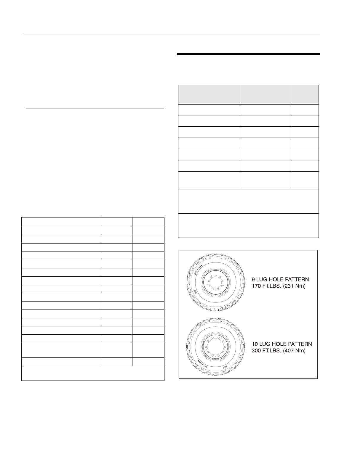
SECTION 1 - SPECIFICATIONS
Figure 1-1. 600S Lug Torques
Platform Rotate: Platform level and completely rotated
one direction. Rotate the opposite direction, Record Time.
Rotate the other direction, Record Time.
Articulating Jib: Platform level and centered with the
boom. Start with the Jib down. Jib Up, Record Time. Jib
Down, Record Time.
Te s t No te s
1. Stop watch should be started with the function, not
with the controller or switch.
2. All speed tests are run from the platform. These
speeds do not reflect the ground control operation.
3. The platform speed knob control must be at full
speed (turned clockwise completely).
4. Function speeds may vary due to cold, thick hydraulic oil. Test should be run with the oil temperature
above 100° F (38° C).
5. Some flow control functions may not work with the
speed knob clicked into the creep position.
Table 1-1. Function Speeds (In Seconds)
Function 600S 600A
Lift Up 46-60 26-32
Lift Down 33-43 26-32
Swing Right & Left* 79-101 79-101
Telescope Out 50-67 35-50
Telescope In 25-33 22-30
Platform Rotate Right & Lef t** 16-25 16-25
Jib Up 22-34 22-34
Jib Down 16-26 16-26
Lower Lift Up N.A. 37-50
Lower Lift Down N.A. 28-38
Lower Telescope Out N.A. 15-23
Lower Telescope In N.A. 09-15
Drive Forward & Reverse (2WD) 28-33 35-42
Drive Forward & Reverse (4WD) 31-37 31-37
Drive Above Horizontal - Forward &
Reverse (2WD & 4WD)
Drive Horizontal - Forward & Reverse N.A. 84-70
*Max 10% Difference Between Left & Right
**Max 15% Difference Between Left & Right
43-136 43-136
4150130 -E
1.5 TORQUE REQUIREMENTS
Table 1-2. Torque Requirements
Description To r q u e Valu e ( Dr y)
Bearing To Chassis See Note 50/600*
Bearing To Turntable See Note 50/600*
Wire Rope 15 ft. lbs (20 Nm) 150
Wheel Lugs (S Models) see Figure 1-1. 150
Wheel Lugs (A Models) 170 ft. lbs. (231 Nm) 150
Engine Mounting Bolts 165 f t. lbs. (231 Nm) A/R
Engine Manifold Mounting
Bolts
*Check swing bearing bolts for security after first 50 hours of operation and every 600 hours thereaf ter. (See Swing Bearing in Section
3.)
NOTE: When maintenance becomes necessary or a fastener
has loosened, refer to the Torque Chart to determine
proper torque value.
30 ft. lbs. (42 Nm) A/ R
Interval
Hours
1-4 – JLG Lift – 3120840
Page 23
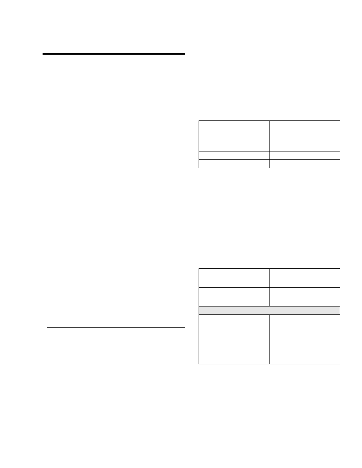
SECTION 1 - SPECIFICATIONS
1.6 LUBRICATION
Deutz F4M1011F Engine
Single Viscosity Oil (CD-SE, CD-SF).
When Outside Temperature is
Consistently
-20°F. to +25°F. (-29°C. to +4°C.) *10W
+5°F. to +50°F. (+15°C. to +10°C.) 20W-20
+40°F. to +85°F. (+4°C. to +30°C.) 30
Above 75°F. (24°C.) 40
Multi Viscosity Oil (CD-SE, CD-SF)
*This viscosity can be used at colder temperatures with
engine oil preheating.
When Outside
Tem pe ra t ur e is
Consistently
-40°F. to +75°F. (-40°C. to
+24°C.)
-15°F. to +70°F. (-26°C. to
+21°C.)
-15°F. to +85°F. (-26°C. to
+30°C.)
Above -5°F. (-21°C.) 15W-40
-5°F. to +75°F. (-21°C. to
+24°C.)
*This viscosity can be used at colder temperatures with
engine oil preheating.
NOTE: Crankcase oil should be MIL-L2104B/MIL-L2104C or
have properties of API classification CC/CD grades.
Use SAE Viscosity
Number
Use SAE Viscosity Number
*5W-30 (Synthetic)
10W-30
10W-40
15W-30
Continental TMD27 Engine
Single Viscosity Oils (CC-CD).
When Outside
Tem pe ra t ur e is
Consistently
+32°F. to +77°F. (+0°C. to
+25°C.)
Above +77°F. (+25°C.) 30
Below +32°F. (+0°C.) 10W
Multi Viscosity Oil (CC-CD)
*Not recommended for severe service, including high RPM
operation
Use SAE Viscosity Number
20
When Outside
Te m pe r at u re is
Consistently
Below +32°F. (+0°C.) 10W-30
Use SAE Viscosity Number
Hydraulic Oil
Table 1-3. Hydraulic Oil
HYDRAULIC SYSTEM
OPERATING
TEMPERATURE RANGE
-18° C to +83° C 10W
-18° C to +99° C 10W-20, 10W-30
+10° C to +210° C 20W-20
NOTE: Hydraulic oils must have anti-wear qualities at least
to API Service Classification GL-3, and sufficient
chemical stability for mobile hydraulic system service. JLG Industries recommends Mobilfluid 424
hydraulic oil, which has an SAE viscosity index of
152.
NOTE: When temperatures remain below 20° F (-7 degrees
C), JLG Industries recommends the use of Mobil
DTE 13M.
Table 1-4. Mobil DTE 13M Specs
ISO Viscosity Grade #32
Specific Gravity 0.877
Pour Point, Max -40°F (-40°C)
Flash Point, Min. 330°F (166°C)
at 40° C 33cSt
at 100° C 6.6 cSt
at 100° F 169 SUS
at 210° F 48 SUS
cp at -20° F 6,200
Viscosity Index 140
Aside from JLG recommendations, it is not advisable to
mix oils of different brands or types, as they may not contain the same required additives or be of comparable viscosities. If use of hydraulic oil other than Mobilfluid 424 is
desired, contact JLG Industries for proper recommendations.
SAE VISCOSITY GRADE
Viscosity
3120840 – JLG Lift – 1-5
Page 24

SECTION 1 - SPECIFICATIONS
Lubrication Specifications
Table 1-5. Lubrication Specifications
KEY SPECIFICATIONS
MPG
EPGL
HO
EO
NOTE: Refer to Lubrication Chart, for specific lubrication
procedures.
Multipurpose Grease having a minimum dripping point of 350° F. Excellent water resistance and adhesive
qualities, and being of extreme pressure type.
(Timken OK 40 pounds minimum.)
Extreme Pressure Gear Lube (oil)
meeting API service classification
GL-5 or MIL- Spec MIL-L-2105
Hydraulic Oil. API service classification GL-3, e.g. Mobilfluid 424.
Engine (crankcase) Oil. Gas - API SF,
SH, SG class, MIL-L-2104. Diesel API CC/CD class, MIL-L-2104B/MILL-2104C.
1.7 PRESSURE SETTINGS
Rexroth Valve (S Models)
Main Relief - 207 Bar.
Upper Boom Lift Down - 103 Bar.
Swing - 117 Bar.
Steer - 124 Bar.
Steer Reliefs - 4WS Front & Rear - 172 Bar.
Platform Level Forward - 193 Bar.
Backward - 124 Bar.
Articulating Jib Boom Up - 103 Bar.
Down - 83 Bar.
Rexroth Valve (A Models)
Main Relief - 207 Bar.
Upper Boom Lift Down - 83 Bar.
Swing - 117 Bar.
Platform Level Forward - 193 Bar.
Backward - 124 Bar.
Steer - 124 Bar.
Steer Reliefs - 4WS Front & Rear - 172 Bar.
Articulating Jib Boom Up - 103 Bar.
Down - 83 Bar.
1-6 – JLG Lift – 3120840
Page 25

SECTION 1 - SPECIFICATIONS
1.8 CYLINDER SPECIFICATIONS
Table 1-6. Cylinder Specifications (S Models)
DESRIPTON BORE STROKE ROD DIA.
600SJ 660SJ 600S 600SJ 660SJ 600S 600SJ 660SJ 600S
Lift 6.00
Tel e sc op e 3. 5
Steer 2.5
Lockout (2wd) 4
Master 3.5
Slave Level 3.5
Lift (Ar ticulating
Jib Boom)
(152.4)
(88.9)
(63.5)
(101.6)
(88.9)
(88.9)
(76.2)
DESRIPTON BORE STROKE ROD DIA.
Lower Lift 6.5
To we r T el es c op e 3
Upright Level 6
Upper Lift 4
Upper Telescope 3
Steer (2WD/2WSl 2.5
Steer (4WD/2WS) 2.5
Lockout (2WD) 3.5
Lockout (4WD 3.5
Master 3.5
Slave 3.5
Lift (Ar ticulating Jib Boom) 3
6.00
(152.4)
3.5
(88.9)
2.5
(63.5)
4
(101.6)
3.5
(88.9)
3.5
(88.9)
3
3
(76.2)
6.00
(152.4)
3.5
(88.9)
2.5
(63.5)
4
(101.6)
3
(76.2)
3
(76.2)
N/A 25.5
143.1875
44.6875
(1135.1)
(3637)
10.75
(273.1)
3.875
(98.4)
13.0625
(331.8)
13.0625
(331.8)
(647.7)
44.6875
(1135.1)
168.4375
(4278.3)
10.75
(273.1)
3.875
(98.4)
13.0625
(331.8)
13.0625
(331.8)
25.5
(647.7)
44.6875
(1135.1)
177.75
(4514.9)
10.75
(273.1)
3.875
(98.4)
8.5
(215.9)
8.5
(215.9)
N/A 1.5
3
(76.2)
2.5
(63.5)
1.25
(31.8)
1.5
(38.1)
1.5
(38.1)
1.5
(38.1)
(38.1)
3
(76.2)
2.5
(63.5)
1.25
(31.8)
1.5
(38.1)
1.5
(38.1)
1.5
(38.1)
1.5
(38.1)
3
(76.2)
2.5
(63.5)
1.25
(31.8)
1.5
(38.1)
1.5
(38.1)
1.5
(38.1)
N/A
Table 1-7. Cylinder Specifications (A Models)
600AJ 600A 600AJ 600A 600AJ 600A
(165.1)
(76.2)
(152.4)
(101.6)
(76.2)
(63.5)
(63.5)
(88.9)
(88.9)
(88.9)
(88.9)
(76.2)
6.5
(165.1)
3
(76.2)
6
(152.4)
4
(101.6)
3
(76.2)
2.5
(63.5)
2.5
(63.5)
3.5
(88.9)
3.5
(88.9)
3
(76.2)
3
(76.2)
N/A 25.5
34.0625
(865.2)
63.75
(1619.3)
34.625
(879.5)
36.625
(930.3)
134.375
(3413.1)
8.812
(204.7)
10.75
(273.1)
3.875
(98.4)
3.875
(98.4)
13.0625
(331.8)
13.0625
(331.8)
(647.7)
34.0625
(865.2)
63.75
(1619.3)
34.625
(879.5)
36.625
(930.3)
177.75
(4514.9)
8.812
(204.7)
10.75
(273.1)
3.875
(98.4)
3.875
(98.4)
8.5
(215.9)
8.5
(215.9)
N/A 1.5
2.5
(63.5)
2
(50.8)
3
(76.2)
2.5
(63.5)
2
(50.8)
1.25
(31.8)
1.25
(31.8)
2.5
(63.5)
2.5
(63.5)
1.5
(38.1)
1.5
(38.1)
(38.1)
2.5
(63.5)
2
(50.8)
3
(76.2)
2.5
(63.5)
2
(50.8)
1.25
(31.8)
1.25
(31.8)
2.5
(63.5)
2.5
(63.5)
1.5
(38.1)
1.5
(38.1)
N/A
3120840 – JLG Lift – 1-7
Page 26
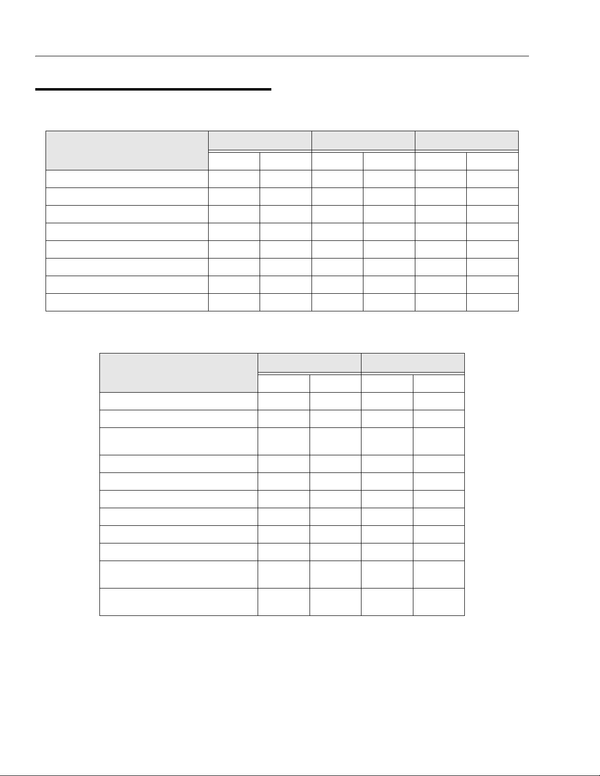
SECTION 1 - SPECIFICATIONS
1.9 MAJOR COMPONENT WEIGHTS
Table 1-8. Major Component Weights (S Models)
600SJ 660SJ 600S
LB. KG. LB. KG. LB. KG.
Platform Control Console 250 113 250 113 250 113
Platform Level Cylinder 60 27 60 27 46 21
Main Boom (Includes Lif t Cyl., Rotator, and Suppor t) 3483 1580 3783 1716 3527 1600
Turntable Complete (including engine) 7915 3590 90 65 4112 7315 3318
Chassis Complete (w/pneumatic tires) 11300 5126 11775 5341 10400 4718
Chassis Complete (w/foam-filled tires) 12580 5707 13055 5922 11680 5300
Machine Complete (GVW) - 2WD w/pneumatic tires 23500 10660 25500 11567 22000 9979
Machine Complete (GVW) - 4WD w/pneumatic tires 23980 10877 25910 11753 22510 1021 1
Table 1-9. Major Component Weights (A Models)
600AJ 600A
LB. KG. LB. KG.
Platform Control Console 250 113 250 113
Platform Level Cylinder 60 27 46 21
Main Boom (Includes Lift Cyl., Rotator, and Support)
Upright including Master Cylinder 547 248 547 2 48
Upright Level Cylinder 316 143 316 143
Tower Boom Complete 1218 553 1218 553
Turntable Complete (including engine) 9740 4418 9240 4191
Chassis Complete (w/pneumatic tires) 6834 310 0 6834 3100
Chassis Complete (w/foam-filled tires) 7918 359 2 7918 3592
Machine Complete (GVW) - 2WD w/pneumatic
tires
Machine Complete (GVW) - 4WD w/pneumatic
tires
1685 764 1832 831
22100 10025 20700 9390
22295 10113 21150 9594
1-8 – JLG Lift – 3120840
Page 27
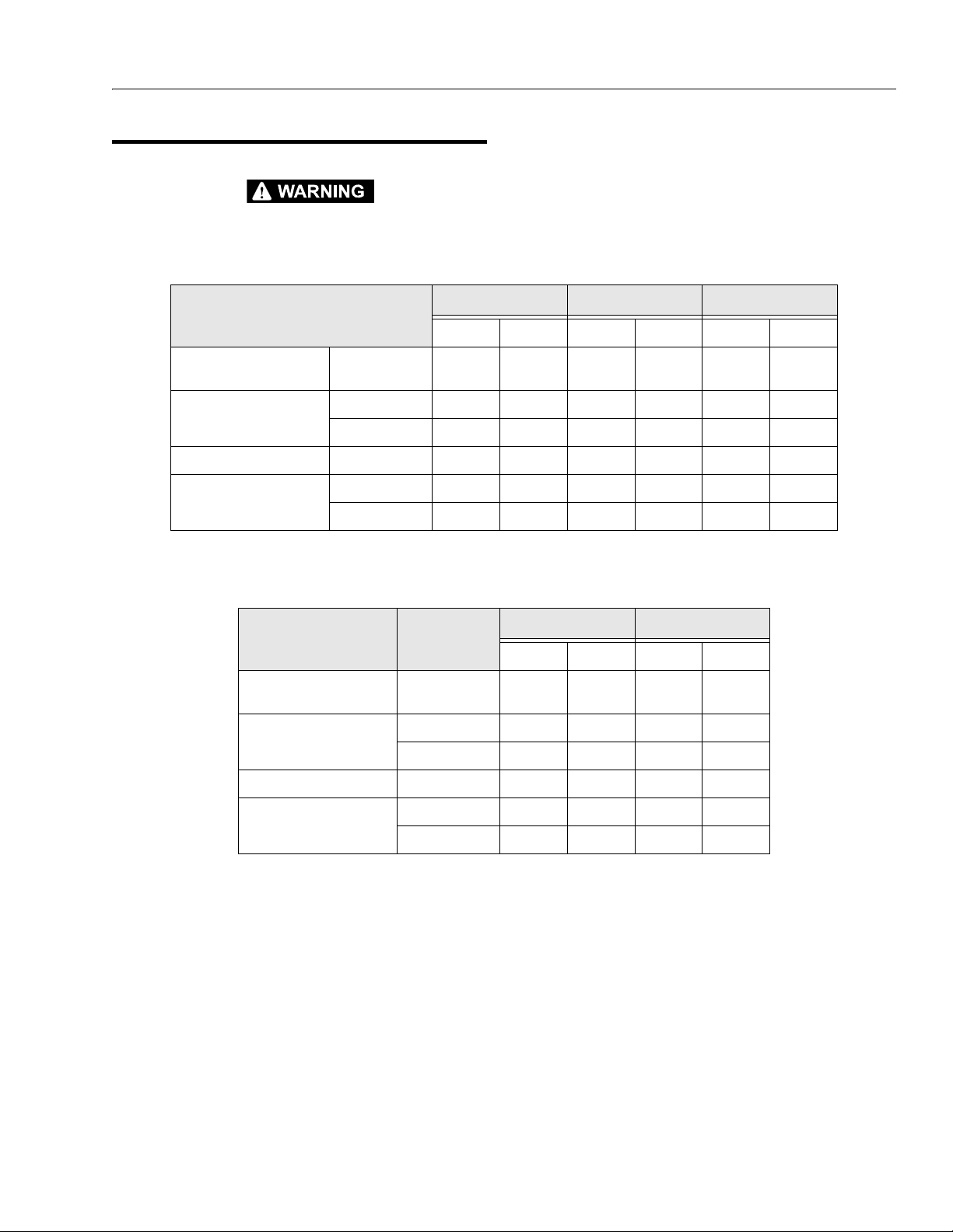
1.10 CRITICAL STABILITY WEIGHTS
SECTION 1 - SPECIFICATIONS
DO NOT REPLACE ITEMS CRITICAL TO STABILITY WITH
ITEMS OF DIFFERENT WEIGHT OR SPECIFICATION (FOR
Table 1-10. Critical Stability Weights (S Models)
Tire and Wheel (Ballasted
Only)
Engine Deutz 534 242 534 242 534 242
Counterweight Weight 3500 1588 4650 2109 2900 1315
Platform 6 f t. (1.83 M) 205 93 205 93 205 93
Size (15 - 19.5) 253 115 253 115 253 115
Continental 558 253 558 253 558 253
8 ft. (2.44 M) 230 105 230 105 230 105
Table 1-11. Critical Stability Weights (A Models)
EXAMPLE: BATTERIES, FILLED TIRES, COUNT
ENGINE & PLATFORM) DO NOT MODIFY UNIT IN ANY WAY TO
AFFECT STABILITY.
600SJ 660SJ 600S
LB. KG. LB. KG. LB. KG.
600AJ 600A
ERWEIGHT,
LB. KG. LB. KG.
Tire and Wheel (Ballasted
Only)
Engine Deutz 534 242 534 242
Counterweight Weight 6200 2812 5700 2586
Platform 6 f t. (1.83 M) 205 93 205 93
Size (14-17.5) 165 75 165 75
Continental 558 253 558 253
8 ft. (2.44 M) 230 105 230 105
3120840 – JLG Lift – 1-9
Page 28
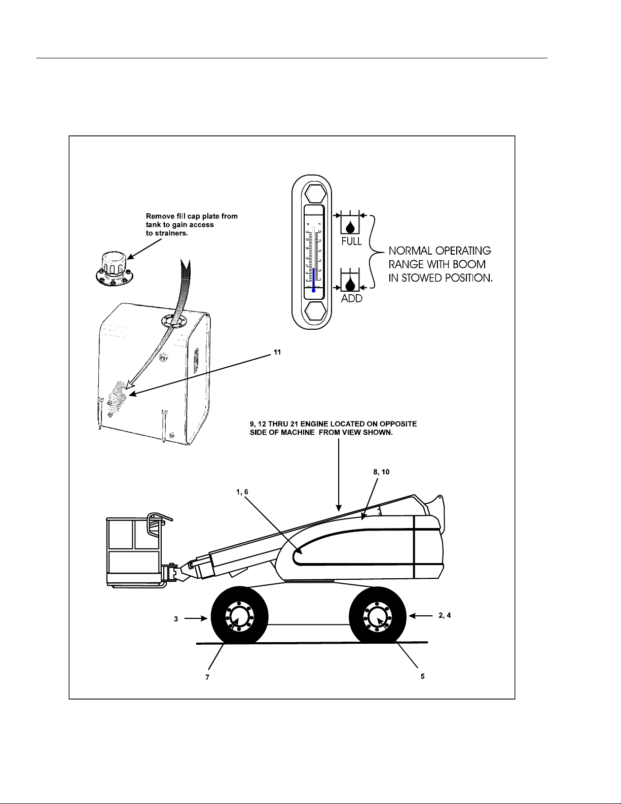
SECTION 1 - SPECIFICATIONS
Figure 1-2. Lubrication Point Location - S Models
1-10 – JLG Lift – 3120840
Page 29
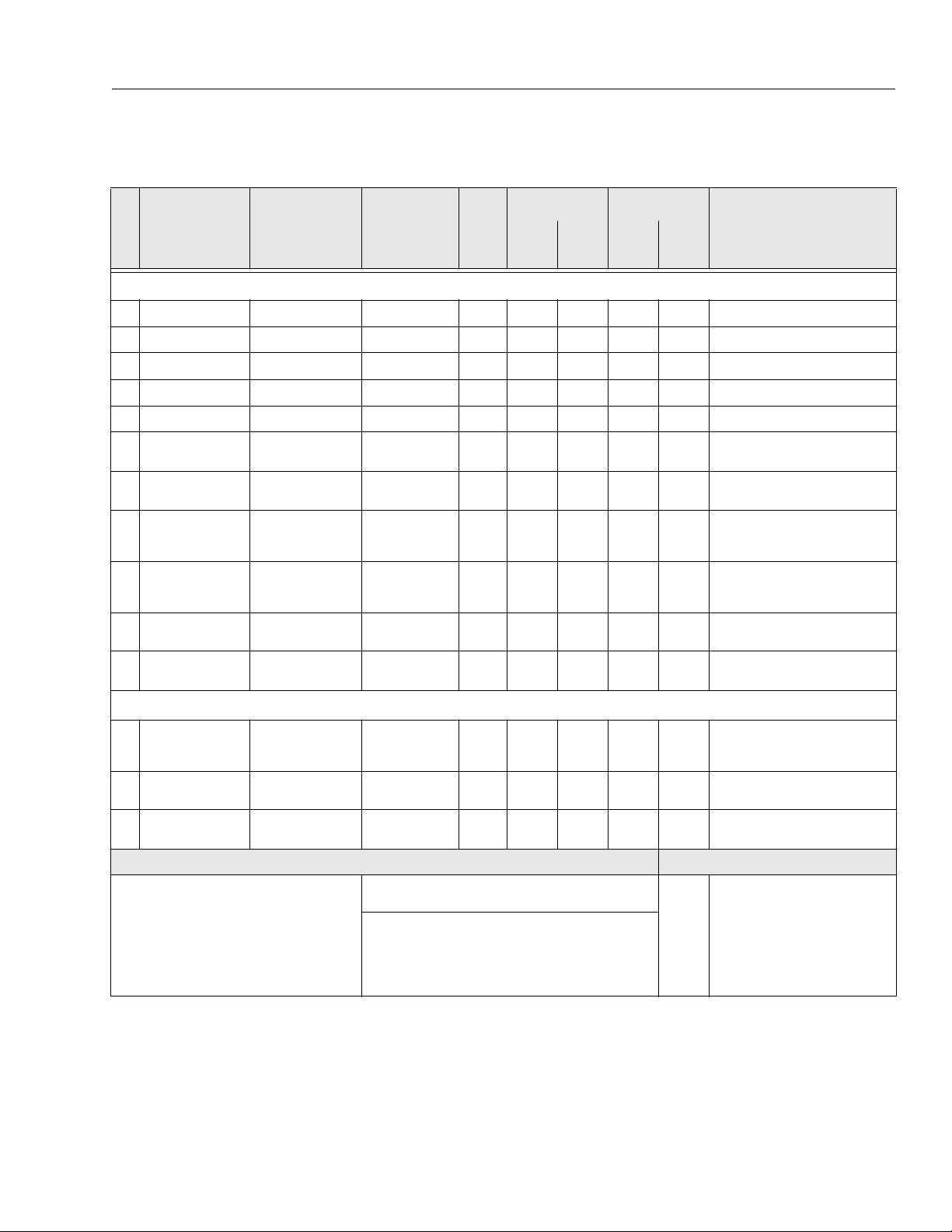
Components
Lubrication
Swing Bearing
1
Steer Spindles (2WS)*
2
Steer Spindles (4WS)*
3
Steer Spindles (4WD)*
4
Wheel Bearings
5
Swing Drive Hub
6
Wheel Drive Hub
7
Hydraulic Return Filter
8
Hydraulic Charge Filter
9
Hydraulic Oil
1
0
Suction Strainers (in tank)
1
1
SECTION 1 - SPECIFICATIONS
Table 1-12. Lubrication Chart - S Models
Interval Hours
Number/Type
Lube Points
2 Grease Fittings A/R MPG X Remote Access
8 Grease Fittings A/R MPG X
2 Grease Fittings A/R MPG X
4 Grease Fittings A/R MPG X
Repack A/R MPG X
Level/Fill Plug 0.5 liters (1/2 Full) EPGL X Check level every 150 hrs/change 1200
Level/Fill Plug 0.5 liters (1/2 Full) EPGL X Check level every 150 hrs/change 1200
N/A N/A N/A X Change after first 50 hrs. and every 300
N/A N/A N/A X Change after first 50 hrs. and every 300
Fill Cap 116 liters Tank
2 N/A N/A X Remove and clean at time of hydraulic oil
Capacity Lube
139 liters System
3
Months
150 hrs
6
Months
300 hrs
1 Year
600 hrs
2 Years
1200
hrs
Comments
hours
hours
hrs. thereafter or as indicated by Condition
Indicator.
hrs. thereafter or as indicated by Condition
Indicator.
HO X Check level daily/change 1200 hours
change.
Engines
Oil Change w/Filter - Deutz
1
2
Fuel Filter - Deutz
1
3
Air Filter - Deutz
1
4
NOTES: KEY TO LUBRICANTS
Lubrication intervals are based on ma chine operation under
normal conditions. For machin es used in multi shift operatio ns
and/or exposed to hostile en vironments or conditions, lubrication frequencies must be increased accordingly.
Fill Cap/Spin-on Ele-
ment
10.5 liters Crankcase
**4.5 liters Cooler
EO X Check level daily/Change in accordance
with engine manual.
Replaceable Element N/A N/A X
Replaceable Element N/A N/A X Or as indicated by Condition Indicator.
* Machines after S /N 38047 will have composite bushing s and no grease
fittings.
** When changing oil in the Deutz oil cooled engine, drain both the crankcase and the cooler. When refilling it is acceptable to over fill the crankcase
(16 liters, capacity of both crankcase and cooler combined). Star t engine,
allow the engine to run until the thermostat opens (approximately 105
degrees C) cooler will fill up within minutes; shut down and wait for approximately two minutes. Check oil level, fill oil to max marking on the dipstick.
EO
Engine Oil
EPGL
Extreme Pressure Gear Lube
HO
Hydraulic Fluid (Mobil #424 or equiva-
MPG
lent)
Multi-Purpose Grease
3120840 – JLG Lift – 1-11
Page 30
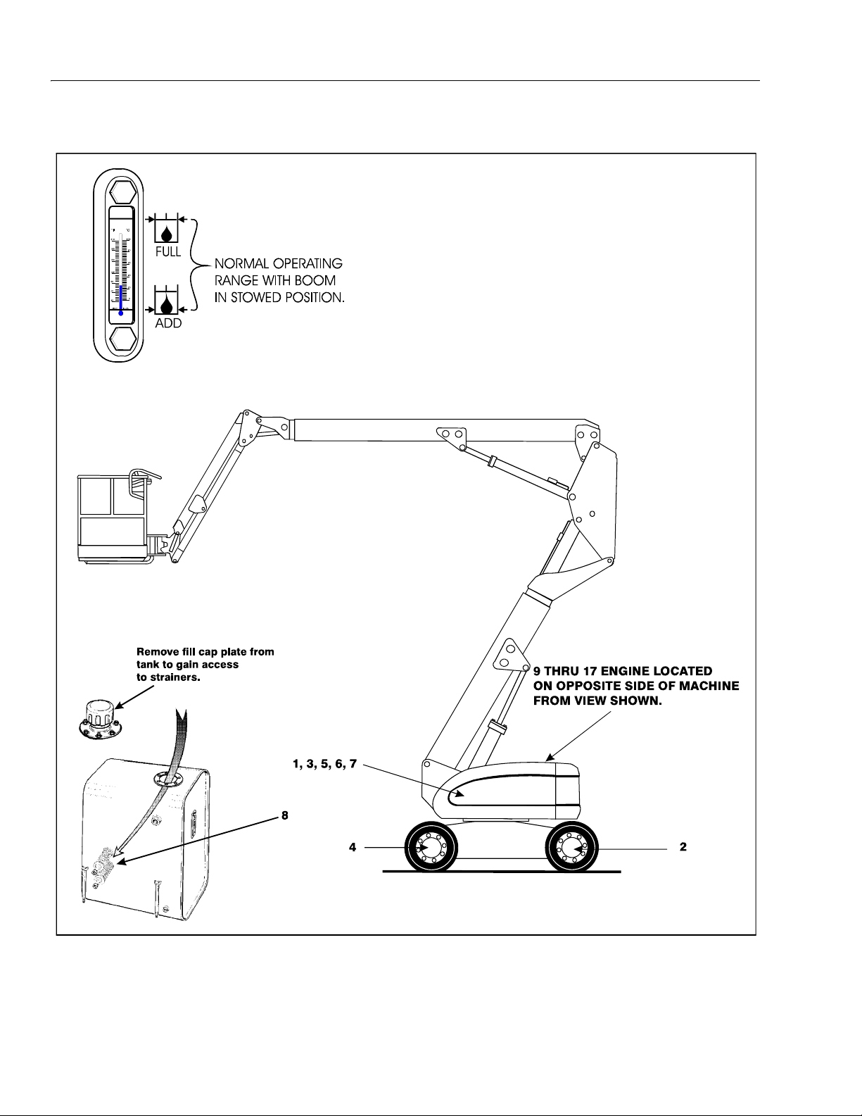
SECTION 1 - SPECIFICATIONS
Figure 1-3. Lubrication Point Location - A Models
1-12 – JLG Lift – 3120840
Page 31

Components
Lubrication
Swing Bearing
1
Wheel Bearings
2
Swing Drive Hub
3
Wheel Drive Hub
4
Hydraulic Return Filter
5
Hydraulic Charge Filter
6
Hydraulic Oil
7
Suction Strainers (in tan k)
8
SECTION 1 - SPECIFICATIONS
Table 1-13. Lubrication Chart - A Models
Interval Hours
Number/Type
Lube Points
2 Grease Fittings A/R MPG X Remote Access
Repack A/R MPG X
Level/Fill Plug 0.5 liters (1/2 Ful)l EPGL X Check level ever y 150 hrs/change 1200
Level/Fill Plug 0.5 liters (1/2 Full) EPGL X Check level ever y 150 hrs/change 1200
N/A N/A N/A X Change after first 50 hrs. and every 300
N/A N/A N/A X Change after first 50 hrs. and every 300
Fill Cap 116 lite rs Tank
2 N/A N/A X Remove and clean at time of hydraulic oil
Capacity Lube
139 liters System
3
Months
150 hrs
6
Months
300 hrs
1 Year
600 hrs
2 Years
1200
hrs
Comments
hours
hours
hrs. thereafter or as indicated by Condition
Indicator.
hrs. thereafter or as indicated by Condition
Indicator.
HO X Check level daily/change 1200 hours
change.
Engines
Oil Change w/Filter
9
Fuel Filter - Deutz
1
0
Air Filter - Deutz
1
1
NOTES: KEY TO LUBRICANTS
Lubrication inter vals are based on machine operation unde r
normal conditions. For machines used in multi shift operations
and/or exposed to hostile enviro nments or conditions, lubrication frequencies must be increased accordingly.
Fill Cap/Spin-on Ele-
ment
10.5 liters Crankcase
*4.5 liters Cooler
EO X Check level daily/Change in accordance
with engine manual.
Replaceable Element N/A N/A X
Replaceable Element N/A N/A X Or as indicated by Condition Indicator.
* When changing oil in the Deutz oil cooled engine, drain both t he crankcase
and the cooler. When refilling it is acceptable to overfill the crankcase (16
liters, capacity of both crankcase and cooler com bined). Start engine, allow
the engine to run until the thermostat opens (approximately 105 degrees C)
cooler will fill up within minutes; shut down and wait for app roximately two
minutes. Check oil level, fill oil to max marking on the dipstick.
EO
Engine Oil
EPGL
Extreme Pressure Gear Lube
Hydraulic Fluid (Mobil #424 or equiva-
HO
lent)
MPG
Multi-Purpose Grease
3120840 – JLG Lift – 1-13
Page 32

SECTION 1 - SPECIFICATIONS
Figure 1-4. Serial Number Locations
1.11 SERIAL NUMBER LOCATIONS
A serial number plate is affixed to the left rear side of the
frame. If the serial number plate is damaged or missing,
the machine serial number is stamped on the left side of
the frame.
1-14 – JLG Lift – 3120840
Page 33

SIZE
4
12
12
6
6
7
7
8
9
12
12
12
14
16
18
18
20
20
24
24
20
24
32
32
40
10
11
12
13
14
16
18
28
32
36
40
48
6
1-1/2
1-1/2
3.8100
3.4925
4.0132
39781
2983
2224
3118
4827
4712
4068
3559
2983
2712
2136
1898
1492
3200
2766
2413
2034
1844
1464
4284
3688
3227
2712
2468
1953
1736
1356
983
895
631
570
359
326
258
224
183
1003
922
678
624
434
380
244
231
176
149
895
814
570
515
326
298
231
204
163
149
21
18
16
12
95
68
61
34
34
8
7
5
5
3
3
2
2
5
4
4
2
2
1
1
142200
57380
53570
47174
43818
38554
34927
31162
27080
23360
20775
18870
15241
13653
10433
9231
8278
7539
6532
5783
4854
4332
3583
3175
2821
2141
1488
1297
817
717
599
572
417
372
272
245
1708
2373
1247
1762
895
1254
719
997
475
705
298
448
176
258
1980
2746
1492
2068
1139
1593
814
1139
651
915
434
644
271
387
149
224
122
183
88
136
109
163
75
115
48
75
31
48
18
26
10
16
4
9
12
4
3
2
1
3
2
1
68
81
34
54
19
29
2278
2630
1980
1519
1681
1193
949
1085
868
583
353
637
407
231
163
204
149
122
75
102
68
41
23
11
5
4
2
1
14
6
4
2
1
48
26
33113
35381
29076
24404
19187
17509
13336
9662
6532
5262
4105
3085
3425
2540
1678
2241
1515
1052
583
426
277
191
916
508
408
263
172
27035
21546
19142
14697
10796
7394
5874
4854
3.3401
3.5687
2.9337
2.4613
1.9380
1.5392
1.1735
0.8484
0.5740
0.4623
0.3604
0.2700
0.1969
0.1331
0.0925
0.0508
0.0808
0.0445
0.0356
0.0232
0.0153
0.0374
0.0258
0.0168
2.7254
2.1742
1.6840
1.2929
0.9474
0.6502
0.5156
0.4061
0.3015
0.2230
0.1473
3.1750
2.8575
2.5400
2.2225
1.9050
1.5875
1.4288
1.2700
1.1112
0.9525
0.7938
0.6350
0.4826
0.4166
0.3505
0.2845
1-1/4
1-1/8
1
7/8
3/4
5/8
9/16
1/2
7/16
5/16
3/8
1/4
10
8
THD
SAE GRADE 5 BOLTS& GRADE 2 NUTS
SAE GRADE 5
SAE GRADE 8
SAE GRADE 8 BOLTS& GRADE 8 NUTS
UNBRAKO 1960 SERIES
SOCKET HEAD CAP SCREW
WITH LOC-WEL PATCH
BOLT
DIA.
(CM)
CLAMP
LOAD
(KG)
CLAMP
LOAD
(KG)
CLAMP LOAD
(KG)
TORQUE
TORQUE
(DRY OR
LOC. 263)
(DRY OR
LOC. 263)
(LOCTITE
262)
(LOCTITE
262)
(LOCTITE
)
242 OR 271
(LOCTITE
)
242 OR 271
TORQUE
(as received)
(LUB.)
(LUB.)
NM
NM
NM
NM
NM
NM
NM
NM
NM
Note: These torque values do not apply to cadium plated fasteners.
THREAD
STRESS
AREA
(SQ. CM)
1220
109
75
41
41
109
81
75
48
48
27
25
109
14
6
3607
1302
122
19
163
68
5322
1342
122
VALUES FOR ZINC PLATED BOLTS ONLY
UNPLATED
CAP SCREWS
22
23
38
43
68
92
108
133
61
148
183
207
325
363
523
576
785
858
968
1087
1368
1516
1792
2042
2379
2676
18
19
34
37
61
68
95
102
149
156
210
224
285
298
495
542
793
861
1173
1241
1681
1871
2373
2549
3145
3308
4122
4433
71669
63731
59648
52391
48671
43954
38828
34610
30074
27488
23088
20956
16919
15150
11612
10251
9208
8256
7253
6437
5384
4822
3983
3493
2631
2377
1651
1442
1079
931
724
658
456
408
277
244
209
188
146
130
95
85
61
54
34
30
1396
1566
1970
2183
2586
2935
3430
3856
Figure 1-5. Torque Chart
SECTION 1 - SPECIFICATIONS
3120840 – JLG Lift – 1-15
Page 34

SECTION 1 - SPECIFICATIONS
This page left blank intentionally.
1-16 – JLG Lift – 3120840
Page 35

SECTION 2. GENERAL
SECTION 2 - GENERAL
2.1 MACHINE PREPARATION, INSPECTION, AND MAINTENANCE
General
This section provides the necessary information needed
by those personnel that are responsible to place the
machine in operation readiness and maintain its safe
operating condition. For maximum service life and safe
operation, ensure that all the necessary inspections and
maintenance have been completed before placing the
machine into service.
Preparation, Inspection, and Maintenance
It is important to establish and conform to a comprehensive inspection and preventive maintenance program. The
following table outlines the periodic machine inspections
and maintenance recommended by JLG Industries, Inc.
Consult your national, regional, or local regulations for further requirements for aerial work platforms. The frequency
of inspections and maintenance must be increased as
environment, severity and frequency of usage requires.
Pre-Start Inspection
It is the User’s or Operator’s primary responsibility to perform a Pre-Start Inspection of the machine prior to use
daily or at each change of operator. Reference the Operator’s and Safety Manual for completion procedures for the
Pre-Start Inspection. The Operator and Safety Manual
must be read in its entirety and understood prior to performing the Pre-Start Inspection.
Pre-Delivery Inspection and Frequent Inspection
The Pre-Delivery Inspection and Frequent Inspection shall
be performed by a qualified JLG equipment mechanic.
JLG Industries, Inc. recognizes a qualified JLG equipment
mechanic as a person who, by possession of a recognized degree, certificate, extensive knowledge, training, or
experience, has successfully demonstrated the ability and
proficiency to service, repair, and maintain the subject
JLG product model.
The Pre-Delivery Inspection and Frequent Inspection procedures are performed in the same manner, but at different times. The Pre-Delivery Inspection shall be performed
prior to each sale, lease, or rental delivery. The Frequent
Inspection shall be accomplished for each machine in service for 3 months or 150 hours (whichever comes first);
out of service for a period of more than 3 months; or when
purchased used. The frequency of this inspection must be
increased as environment, severity and frequency of
usage requires.
Reference the JLG Pre-Delivery and Frequent Inspection
Form and the Inspection and Preventative Maintenance
Schedule for items requiring inspection during the performance of these inspections. Reference the appropriate
areas of this manual for servicing and maintenance procedures.
Annual Machine Inspection
The Annual Machine Inspection must be performed by a
Factory-Certified Service Technician on an annual basis,
no later than thirteen (13) months from the date of the
prior Annual Machine Inspection. JLG Industries, Inc. recognizes a Factory-Certified Service Technician as a person who has successfully completed the JLG Service
Training School for the subject JLG product model. Reference the machine Service and Maintenance Manual and
appropriate JLG inspection form for performance of this
inspection.
Reference the JLG Annual Machine Inspection Form and
the Inspection and Preventative Maintenance Schedule for
items requiring inspection during the performance of this
inspection. Reference the appropriate areas of this manual for servicing and maintenance procedures.
For the purpose of receiving safety-related bulletins, it is
important that JLG Industries, Inc. has updated ownership
information for each machine. When performing each
Annual Machine Inspection, notify JLG Industries, Inc. of
the current machine ownership.
Preventative Maintenance
In conjunction with the specified inspections, maintenance shall be performed by a qualified JLG equipment
mechanic. JLG Industries, Inc. recognizes a qualified JLG
equipment mechanic as a person who, by possession of a
recognized degree, certificate, extensive knowledge, training, or experience, has successfully demonstrated the
ability and proficiency to service, repair, and maintain the
subject JLG product model.
Reference the Preventative Maintenance Schedule and
the appropriate areas of this manual for servicing and
maintenance procedures. The frequency of service and
maintenance must be increased as environment, severity
and frequency of usage requires.
3120840 – JLG Lift – 2-1
Page 36

SECTION 2 - GENERAL
Table 2-1. Inspection and Maintenance
Ty pe F re qu en cy
Pre-Start Inspec-
tion
Pre-Delivery
Inspection
Frequent Inspec-
tion
Annual Machine
Inspection
Preventative
Maintenance
Annually, no later than 13 months from the
At interval s as specified in the Service and
Prior to use each day; or
At each Operator change.
Prior to each sale, lease, or
rental delivery.
In service for 3 months or 150 hours,
whichever comes first; or
Out of service for a period of mo re than 3
months; or
Purchased used.
date of the prior inspection.
Maintenance Manual.
2.2 SERVICE AND GUIDELINES
General
The following information is provided to assist you in the
use and application of servicing and maintenance procedures contained in this book.
Safety and Workmanship
Your safety, and that of others, is the first consideration
when engaging in the maintenance of equipment. Always
be conscious of weight. Never attempt to move heavy
parts without the aid of a mechanical device. Do not allow
heavy objects to rest in an unstable position. When raising
a portion of the equipment, ensure that adequate support
is provided.
Cleanliness
1. The most important single item in preserving the
long service life of a machine is to keep dirt and foreign materials out of the vital components. Precautions have been taken to safeguard against this.
Shields, covers, seals, and filters are provided to
keep air, fuel, and oil supplies clean; however, these
items must be maintained on a scheduled basis in
order to function properly.
Primary
Responsibility
User or Operator User or Operator Operator and Safety Manual
Owner, Dealer, or User Qualified JLG
Owner, Dealer, or User Qualified JLG
Owner, Dealer, or User Factory-Cer tified
Owner, Dealer, or User Qualified JLG
2. At any time when air, fuel, or oil lines are disconnected, clear adjacent areas as well as the openings
and fittings themselves. As soon as a line or component is disconnected, cap or cover all openings to
prevent entry of foreign matter.
3. Clean and inspect all parts during servicing or maintenance, and assure that all passages and openings
are unobstructed. Cover all parts to keep them
clean. Be sure all parts are clean before they are
installed. New parts should remain in their containers until they are ready to be used.
Service
Qualification
Mechanic
Mechanic
Service Technician
Mechanic
Reference
Service and Maintenance
Manual and applicable JLG
inspection form.
Service and Maintenance
Manual and applicable JLG
inspection form.
Service and Maintenance
Manual and applicable JLG
inspection form.
Service and Maintenance
Manual
Components Removal and Installation
1. Use adjustable lifting devices, whenever possible, if
mechanical assistance is required. All slings (chains,
cables, etc.) should be parallel to each other and as
near perpendicular as possible to top of part being
lifted.
2. Should it be necessary to remove a component on
an angle, keep in mind that the capacity of an eyebolt or similar bracket lessens, as the angle between
the supporting structure and the component
becomes less than 90 degrees.
3. If a part resists removal, check to see whether all
nuts, bolts, cables, brackets, wiring, etc., have been
removed and that no adjacent parts are interfering.
2-2 – JLG Lift – 3120840
Page 37

SECTION 2 - GENERAL
Component Disassembly and Reassembly
When disassembling or reassembling a component, complete the procedural steps in sequence. Do not partially
disassemble or assemble one part, then start on another.
Always recheck your work to assure that nothing has been
overlooked. Do not make any adjustments, other than
those recommended, without obtaining proper approval.
Pressure-Fit Parts
When assembling pressure-fit parts, use an anti-seize or
molybdenum disulfide base compound to lubricate the
mating surface.
Bearings
1. When a bearing is removed, cover it to keep out dirt
and abrasives. Clean bearings in nonflammable
cleaning solvent and allow to drip dry. Compressed
air can be used but do not spin the bearing.
2. Discard bearings if the races and balls (or rollers)
are pitted, scored, or burned.
3. If bearing is found to be serviceable, apply a light
coat of oil and wrap it in clean (waxed) paper. Do not
unwrap reusable or new bearings until they are
ready to install.
4. Lubricate new or used serviceable bearings before
installation. When pressing a bearing into a retainer
or bore, apply pressure to the outer race. If the bearing is to be installed on a shaft, apply pressure to the
inner race.
Gaskets
Check that holes in gaskets align with openings in the
mating parts. If it becomes necessary to hand-fabricate a
gasket, use gasket material or stock of equivalent material
and thickness. Be sure to cut holes in the right location, as
blank gaskets can cause serious system damage.
2. Unless specific torque requirements are given within
the text, standard torque values should be used on
heat-treated bolts, studs, and steel nuts, in accordance with recommended shop practices. (See
Torque Chart Section 1.)
Hydraulic Lines and Electrical Wiring
Clearly mark or tag hydraulic lines and electrical wiring, as
well as their receptacles, when disconnecting or removing
them from the unit. This will assure that they are correctly
reinstalled.
Hydraulic System
1. Keep the system clean. If evidence of metal or rubber particles are found in the hydraulic system, drain
and flush the entire system.
2. Disassemble and reassemble parts on clean work
surface. Clean all metal parts with non-flammable
cleaning solvent. Lubricate components, as
required, to aid assembly.
Lubrication
Service applicable components with the amount, type,
and grade of lubricant recommended in this manual, at
the specified intervals. When recommended lubricants are
not available, consult your local supplier for an equivalent
that meets or exceeds the specifications listed.
Battery
Clean battery, using a non-metallic brush and a solution of
baking soda and water. Rinse with clean water. After
cleaning, thoroughly dry battery and coat terminals with
an anti corrosion compound.
Lubrication and Servicing
Components and assemblies requiring lubrication and
servicing are shown in the Lubrication Chart in Section 1.
Bolt Usage and Torque Application
1. Use bolts of proper length. A bolt which is too long
will bottom before the head is tight against its related
part. If a bolt is too short, there will not be enough
thread area to engage and hold the part properly.
When replacing bolts, use only those having the
same specifications of the original, or one which is
equivalent.
3120840 – JLG Lift – 2-3
Page 38

SECTION 2 - GENERAL
2.3 LUBRICATION AND INFORMATION
Hydraulic System
1. The primary enemy of a hydraulic system is contamination. Contaminants enter the system by various
means, e.g., using inadequate hydraulic oil, allowing
moisture, grease, filings, sealing components, sand,
etc., to enter when performing maintenance, or by
permitting the pump to cavitate due to insufficient
system warm-up or leaks in the pump supply (suction) lines.
2. The design and manufacturing tolerances of the
component working parts are very close, therefore,
even the smallest amount of dirt or foreign matter
entering a system can cause wear or damage to the
components and generally results in faulty operation. Every precaution must be taken to keep
hydraulic oil clean, including reserve oil in storage.
Hydraulic system filters should be checked,
cleaned, and/or replaced as necessary, at the specified intervals required in the Lubrication Chart in
Section 1. Always examine filters for evidence of
metal particles.
3. Cloudy oils indicate a high moisture content which
permits organic growth, resulting in oxidation or corrosion. If this condition occurs, the system must be
drained, flushed, and refilled with clean oil.
3. The only exception to the above is to drain and fill
the system with Mobil DTE 13 oil or its equivalent.
This will allow start up at temperatures down to -20
degrees F (-29 degrees C). However, use of this oil
will give poor performance at temperatures above
120 degrees F (49 degrees C). Systems using DTE
13 oil should not be operated at temperatures above
200 degrees F (94 degrees C) under any condition.
Changing Hydraulic Oil
1. Use of any of the recommended crankcase or
hydraulic oils eliminates the need for changing the
oil on a regular basis. However, filter elements must
be changed after the first 50 hours of operation and
every 300 hours thereafter. If it is necessary to
change the oil, use only those oils meeting or
exceeding the specifications appearing in this manual. If unable to obtain the same type of oil supplied
with the machine, consult local supplier for assistance in selecting the proper equivalent. Avoid mixing petroleum and synthetic base oils. JLG
Industries recommends changing the hydraulic oil
annually.
2. Use every precaution to keep the hydraulic oil clean.
If the oil must be poured from the original container
into another, be sure to clean all possible contaminants from the service container. Always clean the
mesh element of the filter and replace the cartridge
any time the system oil is changed.
4. It is not advisable to mix oils of different brands or
types, as they may not contain the same required
additives or be of comparable viscosities. Good
grade mineral oils, with viscosities suited to the
ambient temperatures in which the machine is operating, are recommended for use.
NOTE: Metal particles may appear in the oil or filters of new
machines due to the wear-in of meshing components.
Hydraulic Oil
1. Refer to Section 1 for recommendations for viscosity
ranges.
2. JLG recommends Mobilfluid 424 hydraulic oil, which
has an SAE viscosity of 10W-30 and a viscosity
index of 152.
NOTE: Start-up of hydraulic system with oil temperatures
below -15 degrees F (-26 degrees C) is not recommended. If it is necessary to start the system in a
sub-zero environment, it will be necessary to heat
the oil with a low density, 100VAC heater to a minimum temperature of -15 degrees F (-26 degrees C).
3. While the unit is shut down, a good preventive maintenance measure is to make a thorough inspection
of all hydraulic components, lines, fittings, etc., as
well as a functional check of each system, before
placing the machine back in service.
Lubrication Specifications
Specified lubricants, as recommended by the component
manufacturers, are always the best choice, however,
multi-purpose greases usually have the qualities which
meet a variety of single purpose grease requirements.
Should any question arise, regarding the use of greases in
maintenance stock, consult your local supplier for evaluation. Refer to Section 1 for an explanation of the lubricant
key designations appearing in the Lubrication Chart.
2-4 – JLG Lift – 3120840
Page 39

SECTION 2 - GENERAL
2.4 CYLINDER DRIFT TEST
Maximum acceptable cylinder drift is to be measured
using the following methods.
Platform Drift
Measure the drift of the platform to the ground. Lower
booms (if equipped) slightly elevated, upper boom fully
extended with the rated load in the platform and power off.
Maximum allowable drift is 2 inches (5 cm) in 10 minutes.
If the machine does not pass this test, proceed with the
following.
Cylinder Drift
Table 2-2. Cylinder Drift
Cylinder Bore Diameter
inches mm inches mm
3 76.2 0.026 0.66
3.5 89 0.019 0.48
4 101.6 0.015 0.38
5 127 0.009 0.22
6 152.4 0.006 0.15
7 177.8 0.005 0.13
8 203.2 0.0038 0.10
9 228.6 0.0030 0.08
Max. Acceptable Drift
in 10 Minutes
2.5 PINS AND COMPOSITE BEARING REPAIR GUIDELINES
Filament wound bearings.
1. Pinned joints should be disassembled and
inspected if the following occurs:
a. Excessive sloppiness in joints.
b. Noise originating from the joint during operation.
2. Filament wound bearings should be replaced if any
of the following is observed:
a. Frayed or separated fibers on the liner surface.
b. Cracked or damaged liner backing.
c. Bearings that have moved or spun in their hous-
ing.
d. Debris embedded in liner surface.
3. Pins should be replaced if any of the following is
observed (pin should be properly cleaned prior to
inspection):
a. Detectable wear in the bearing area.
b. Flaking, pealing, scoring, or scratches on the pin
surface.
c. Rusting of the pin in the bearing area.
4. Re-assembly of pinned joints using filament wound
bearings.
Drift is to be measured at the cylinder rod with a calibrated
dial indicator. The cylinder oil must be at ambient temperature and temperature stabilized.
The cylinder must have the normal load, which is the normal platform load applied.
If the cylinder passes this test, it is acceptable.
NOTE: This information is based on 6 drops per minute cyl-
inder leakage.
a. Housing should be blown out to remove all dirt
and debris...bearings and bearing housings
must be free of all contamination.
b. Bearing / pins should be cleaned with a solvent
to remove all grease and oil...filament wound
bearing are a dry joint and should not be lubricated.
c. Pins should be inspected to ensure it is free of
burrs, nicks, and scratches which would damage the bearing during installation and operation.
3120840 – JLG Lift – 2-5
Page 40

SECTION 2 - GENERAL
2.6 WELDING ON JLG EQUIPMENT
NOTE: This instruction applies to repairs, or modifications to
the machine and to welding performed from the
machine on an external structure, or component,
Do the Following When Welding on JLG Equipment
• Disconnect the battery.
• Disconnect the moment pin connection (where fitted)
• Ground only to structure being welded.
Do NOT Do the Following When Welding on JLG Equipment
• Ground on frame and weld on any other area than the
chassis.
• Ground on turntable and weld on any other area than
the turntable.
• Ground on the platform/support and weld on any other
area than the platform/support.
• Ground on a specific boom section and weld on any
other area than that specific boom section.
• Allow pins, wear pads, wire ropes, bearings, gearing,
seals, valves, electrical wiring, or hoses to be between
the grounding position and the welded area.
FAILURE TO COMPLY WITH THE ABOVE REQUIREMENTS MAY
RESULT IN COMPONENT DAMAGE (I.E. ELECTRONIC MODULES,
SWING BEARING, COLLECTOR RING, BOOM WIRE ROPES ETC.)
2.7 APPLYING SILICONE DIELECTRIC COMPOUND TO ELECTRICAL CONNECTIONS
Silicone Dielectric Compound must be used on all electrical connections for the following reasons:
• To prevent oxidation at the mechanical joint between
male and female pins.
• To prevent electrical malfunction caused by low level
conductivity between pins when wet.
Use the following procedure to apply Silicone Dielectric
Compound to the electrical connectors. This procedure
applies to all plug connections not enclosed in a box. Silicone grease should not be applied to connectors with
external seals.
1. To prevent oxidation, silicone grease must be
packed completely around male and female pins on
the inside of the connector prior to assembly. This is
most easily achieved by using a syringe.
NOTE: Over a period of time, oxidation increases electri cal
resistance at the connection, eventually causing circuit failure.
2. To prevent shorting, silicone grease must be packed
around each wire where they enter the outside of the
connector housing. Also, silicone grease must be
applied at the joint where the male and female connectors come together. Any other joints (around
strain reliefs, etc.) where water could enter the connector should also be sealed.
NOTE: This condition is especially co mmon whe n machines
are pressure washed since the washing solution is
much more conductive than water.
3. Anderson connectors for the battery boxes and battery chargers should have silicone grease applied to
the contacts only.
NOTE: Curing-type sealants might also be used to prevent
shorting and would be less messy, but would make
future pin removal more difficult.
2-6 – JLG Lift – 3120840
Page 41

SECTION 2 - GENERAL
Figure 2-1. Connector Assembly Figure 1
Figure 2-2. AMP Connector
2.8 AMP CONNECTOR
Applying Silicone Dielectric Compound to AMP Connectors
Silicone Dielectric Compound must be used on the AMP
connections for the following reasons:
• To prevent oxidation at the mechanical joint between
male and female pins.
• To prevent electrical malfunction caused by low level
conductivity between pins when wet.
Use the following procedure to apply Silicone Dielectric
Compound to the electrical connectors.
1. To prevent oxidation and low level conductivity, silicone dielectric grease must be packed completely
around male and female pins on the inside of the
connector after the mating of the housing to the
header. This is easily achieved by using a syringe to
fill the header with silicone dielectric compound, to a
point just above the top of the male pins inside the
header. When assembling the housing to the
header, it is possible that the housing will become
air locked, thus preventing the housing latch from
engaging.
2. Pierce one of the unused wire seals to allow the
trapped air inside the housing to escape.
3. Install a hole plug into this and/or any unused wire
seal that has silicone dielectric compound escaping
from it.
Assembly
Check to be sure the wedge lock is in the open, or asshipped, position (See Figure 2-1.). Proceed as follows:
1. To insert a contact, push it straight into the appropriate circuit cavity as far as it will go (See Figure 2-3.).
2. Pull back on the contact wire with a force of 1 or 2
lbs. to be sure the retention fingers are holding the
contact (See Figure 2-3.).
3120840 – JLG Lift – 2-7
Page 42

SECTION 2 - GENERAL
Figure 2-3. Connector Assembly Figure 2
Figure 2-4. Connector Assembly Figure 3
Figure 2-5. Connector Assembly Figure 4
3. After all required contacts have been inserted, the
wedge lock must be closed to its locked position.
Release the locking latches by squeezing them
inward (See Figure 2-4.).
4. Slide the wedge lock into the housing until it is flush
with the housing (See Figure 2-5.).
2-8 – JLG Lift – 3120840
Page 43

SECTION 2 - GENERAL
Figure 2-6. Connector Disassembly
Disassembly
1. Insert a 4.8 mm (3/16") wide screwdriver blade
between the mating seal and one of the red wedge
lock tabs.
2. Pry open the wedge lock to the open position.
3. While rotating the wire back and forth over a half
turn (1/4 turn in each direction), gently pull the wire
until the contact is removed.
NOTE: The wedge lock should never b e removed from the
housing for insertion or removal of the contacts.
Wedge Lock
The wedge lock has slotted openings in the forward, or
mating end. These slots accommodate circuit testing in
the field, by using a flat probe such as a pocket knife. DO
NOT use a sharp point such as an ice pick.
Service - Voltage Reading
DO NOT PIERCE WIRE INSULATION TO TAKE VOLTAGE READINGS.
It has been common practice in electrical troubleshooting
to probe wires by piercing the insulation with a sharp
point. This practice should be discouraged when dealing
with the AMPSEAL plug assembly, or any other sealed
connector system. The resulting pinholes in the insulation
will allow moisture to invade the system by traveling along
the wire strands. This nullifies the effectiveness of the connector seals and could result in system failure.
3120840 – JLG Lift – 2-9
Page 44

SECTION 2 - GENERAL
Figure 2-7. Connector Installation
2-10 – JLG Lift – 3120840
Page 45

SECTION 2 - GENERAL
Figure 2-8. DT/DTP Contact Installation
A
B
C
D
Figure 2-9. DT/DTP Contact Removal
A
B
C
2.9 DEUTSCH CONNECTORS
DT/DTP Series Assembly
1. Grasp crimped contact about 25mm behind the contact barrel.
2. Hold connector with rear grommet facing you.
3. Push contact straight into connector grommet until a
click is felt. A slight tug will confirm that it is properly
locked in place.
4. Once all contacts are in place, insert wedgelock with
arrow pointing toward exterior locking mechanism.
The wedgelock will snap into place. Rectangular
wedges are not oriented. Thy may go in either way.
DT/DTP Series Disassembly
1. Remove wedgelock using needlenose pliers or a
hook shaped wire to pull wedge straight out.
2. To remove the contacts, gently pull wire backwards,
while at the same time releasing the locking finger
by moving it away from the contact with a screwdriver.
3. Hold the rear seal in place, as removing the contact
may displace the seal.
NOTE: The receptacle is shown - use the same procedure
for plug.
3120840 – JLG Lift – 2-11
Page 46

SECTION 2 - GENERAL
Figure 2-10. HD/HDP Contact Installation
A
B
C
Figure 2-11. HD/HDP Locking Contacts Into Position
Figure 2-12. HD/HDP Contact Removal
AB
C
Figure 2-13. HD/HDP Unlocking Contacts
HD30/HDP20 Series Assembly
1. Grasp contact about 25mm behind the contact
crimp barrel.
2. Hold connector with rear grommet facing you.
3. Push contact straight into connector grommet until a
positive stop is felt. A slight tug will confirm that it is
properly locked in place.
HD30/HDP20 Series Disassembly
1. With rear insert toward you, snap appropriate size
extractor tool over the wire of contact to be
removed.
2. Slide tool along into the insert cavity until it engages
contact and resistance is felt.
3. Pull contact-wire assembly out of connector.
NOTE: For unused wire cavitie s, insert sealing plugs for full
environmental sealing
2-12 – JLG Lift – 3120840
NOTE: Do not twist or insert tool at an angle.
Page 47

Table 2-3. Inspection and Preventive Maintenance Schedule
INTERVAL
SECTION 2 - GENERAL
Pre-
Delivery
or Frequent
Inspection
2
3
AREA
Boom Assembly
Boom Weldments 1,2,4 1,2,4
Hose/Cable Carrier Installations 1,2,9,12 1,2,9,12
Pivot Pins and Pin Retainer s 1,2 1, 2
Sheaves, Sheave Pins 1,2 1,2
Bearings 1,2 1,2
Wear Pads 1,2 1,2
Covers or Shields 1,2 1,2
Extend/Retract Chain or Cable Systems 1,2,3 1,2,3
Platform Assembly
Platform 1,2 1,2
Railing 1,2 1 1,2
Gate 511,5
Floor 1,2 1 1,2
Rotator 9,5
Lanyard Anchorage Point 2 1,2,10 1,2,10
Tur nt ab le Assem bl y
Swing Bearing or Worm Ge ar 1,2,14 1,2,3,13,14
Oil Coupling 9
Swing Drive System
Tur n ta bl e L oc k 1,2,5 1,2,5
Hood, Hood Props, Hood Latches 5 1,2,5
Chassis Assembly
Tires 1 16,17 16,17,18 16,17,18
Wheel Nuts/Bolts 1 15 15 15
Wheel Bearings 14,24
Oscillating Axle/Lockout Cylinder Systems 5,8
Outrigger or Extendable Axle Systems 5,8 5,8
Steer Components
Drive Motors
To rq u e H ub s 11 11
Functions/Controls
Platform Controls 5 5 6 6
Pre-Start
Inspection
9
9
9
9
9
1
Preventive
Maintenance
Weekly
Monthly
Preventive
Maintenance
Annual
(Yearly)
Inspection
4
Every 2
Years
3120840 – JLG Lift – 2-13
Page 48

SECTION 2 - GENERAL
Table 2-3. Inspection and Preventive Maintenance Schedule
INTERVAL
AREA
Pre-Start
Inspection
1
Preventive
Maintenance
Weekly
Monthly
Preventive
Maintenance
Pre-
Delivery
or Frequent
Inspection
2
3
4
Annual
(Yearly)
Inspection
Ground Controls 5 5 6 6
Function Control Locks, Guards, or Detents 1,5 1,5 5 5
Footswitch 1,5 5 5
Emergency Stop Switches (Ground & Platform) 5 5 5
Function Limit or Cutout Switch Systems 5 5
Capacity Indicator 5
Drive Brakes 5
Swing Brakes 5
Boom Synchronization/Sequencing Systems 5
Manual Descent or Auxiliary Power 5 5
Power System
9
Engine Idle, Throttle, and RPM 3 3
Engine Fluids (Oil, Coolant, Fuel) 11 9,11 11 11
Air/Fuel Filter 1,7 7 7
Exhaust System 1,9 9 9
Batteries 5 1,9 19
Battery Fluid 11 11 11
Battery Charger 5 5
Fuel Reservoir, Cap, and Breather 11,9 2 1,5 1,5
Hydraulic/Electric System
9
Hydraulic Pumps 1,9 1,2,9
Hydraulic Cylinders 1,9,7 2 1,2,9 1,2,9
Cylinder Attachment Pi ns and Pin Retainers 1,9 1,2 1,2
Hydraulic Hoses, Lines, and Fittings 1,9 12 1,2,9,12 1,2,9,12
Hydraulic Reservoir, Cap, and Breather 11 1,9 2 1,5 1,5 24
Hydraulic Filter 1,9 7 7
Hydraulic Fluid 11 7,11 7,11
Electrical Connections 1 20 20
Instruments, Gauges, Switches, Lights, Horn 1 5,23
General
Operators and Safety Manuals in Storage Box 21 21 21
ANSI and EMI Manuals/Handbooks Installed 21
Capacity Decals Installed, Secure, Legible 21 21 21
All Decals/Placards Installed, Secure, Legible 21 21 21
Walk-Around Inspection Per formed 21
Every 2
Years
2-14 – JLG Lift – 3120840
Page 49

Table 2-3. Inspection and Preventive Maintenance Schedule
INTERVAL
SECTION 2 - GENERAL
Pre-
Delivery
or Frequent
Inspection
2
3
Annual
(Yearly)
Inspection
AREA
Pre-Start
Inspection
1
Preventive
Maintenance
Weekly
Monthly
Preventive
Maintenance
Annual Machine Inspection Due 21
No Unauthorized Modifications or Additions 21 21
All Relevant Safety Publications Incorporated 21 21
General Structural Condition and Welds 2,4 2,4
All Fasteners, Pins, Shields, and Covers 1,2 1,2
Grease and Lubricate to Specifications 22 22
Function Test of All Systems 21 21 21, 22
Paint and Appearance 7 7
Stamp Inspection Date on Frame 22
Notify JLG of Machine Ownership 22
Footnotes:
1
Prior to use each day; or at each Operator change
2
Prior to each sale, lease, or delivery
3
In service for 3 months or 150 Hours; or Out of service for 3 months or more; or Purchased used
4
Annually, no later than 13 months from the date of the prior inspection
Per for mance Codes :
1 - Check for proper and secure installation
2 - Visual inspection for damage, cracks, distor tion or excessive wear
3 - Check for proper adjustment
4 - Check for cracked or broken welds
5 - Operates Properly
6 - Returns to neutral or "off" position when released
7 - Clean and free of debris
8 - Interlocks function properly
9 - Check for signs of leakage
10 - Decals installed and legible
11 - Check for proper fluid level
12 - Check for chafing and proper routing
13 - Check for proper tolerances
14 - Properly lubricated
15 - Torqued to proper specification
16 - No gouges, excessive wear, or cords showing
17 - Properly inflated and seated around rim
18 - Proper and authorized components
19 - Fully charged
20 - No loose connections, corrosion, or abrasions
21 - Verify
22 - Perform
23 - Sealed Properly
24 - Drain, Clean, Refill
4
Every 2
Years
3120840 – JLG Lift – 2-15
Page 50

SECTION 2 - GENERAL
Figure 2-14. Engine Operating Temperature Specifications - Deutz
4150548 A
2-16 – JLG Lift – 3120840
Page 51

SECTION 3 - CHASSIS & TURNTABLE
SECTION 3. CHASSIS & TURNTABLE
3.1 DRIVE TORQUE HUB, PRIOR TO S/N 75606
Disassembly
1. Position hub over suitable container and remove
drain plugs (10) from unit. Allow oil to completely
drain, then replace drain plugs.
2. Remove eight bolts (41) and four shoulder bolts (42)
securing cover assembly to hub (7). Remove cover
assembly (23) and discard o-ring seal (22).
3. Lift carrier assembly and top thrust washer and
thrust bearing(39, 40) from hub. Thrust washer may
stick inside cover.
4. Pry ring gear (21) loose from hub and remove it.
Remove o-ring seal (22) from hub counter bore and
discard it.
5. Remove input gear (37) and thrust spacer (36) from
input shaft assembly and remove input shaft assembly from hub.
6. Lift internal gear (12) and thrust washer and thrust
bearing (39, 40) from hub. Thrust washer may stick
to bottom of carrier.
7. Remove retaining ring (9) from spindle (1) and discard; lift hub from spindle.
Cleaning and Inspection
1. Thoroughly clean all parts in an approved cleaning
solvent.
2. Inspect bearing cups and cones for damage, pitting,
corrosion, or excessive wear. If necessary, replace
bearings as a complete set ensuring that they
remain covered until use.
3. Inspect bearing mounting surfaces on spindle, hub,
input shaft and carrier. Replace components as necessary.
4. Inspect all geared components for chipped or broken teeth and for excessive or uneven wear patterns.
5. Inspect carrier for damage, especially in anti-roll pin
and planet shaft hole areas.
6. Inspect all planet shafts for scoring or other damage.
7. Inspect all threaded components for damage including stretching, thread deformation, or twisting.
8. Inspect seal mounting area in hub for burrs or sharp
edges. Dress applicable surfaces or replace components as necessary.
9. Inspect cover for cracks or other damage, and oring sealing area for burrs or sharp edges. Dress
applicable surfaces or replace cover as necessary.
EYE PROTECTION SHOULD BE WORN DURING RETAINING RING
REMOVAL.
8. Remove inside bearing cone (6) and bearing shim
(8).
9. If necessary, pry seal (2) out of hub using screwdriver or pry bar. With seal removed, outside bearing
cone (4) can be removed.
10. If necessary, remove inner and outer bearing cones
(3, 5) using a suitable slide hammer puller.
WHEN REBUILDING TORQUE HUB, REMOVE AND REPLACE ALL
O-RINGS AND RETAINING RINGS.
3120840 – JLG Lift – 3-1
Page 52

SECTION 3 - CHASSIS & TURNTABLE
Figure 3-1. Torque Hub, Drive (Fairfield)
3-2 – JLG Lift – 3120840
Page 53

SECTION 3 - CHASSIS & TURNTABLE
Repair
1. Cover Assembly.
a. Remove two bolts (25) securing disconnect cap
(26) to cover (23) and remove cap.
b. Remove two bolts (25) securing cover cap (24)
to cover and remove cap.
c. Remove disconnect rod (27) from cap and
remove o-rings (28, 29) from cover cap. Discard
o-rings.
d. If necessary, remove pipe plug (30) from cover.
e. Clean and inspect parts in accordance with
Cleaning and Inspection procedures. Replace
parts as necessary.
f. If removed, screw pipe plug into cover.
g. Slip o-ring (29) over cover cap and against face.
h. Place o-ring (28) into cover cap internal groove.
Disconnect rod may be used to push o-ring into
groove.
i. Place cover cap into cover with large hole
located over pipe plug. Secure cover cap to
cover with two bolts. Torque bolts to 7.9-9.0 Nm.
h. Apply a coat of grease or petroleum jelly to clus-
ter gear bore.
i. Place sixteen needle rollers into cluster gear
bore.
j. Place disconnect cap over cover cap with nipple
facing out and secure with two bolts. Torque
bolts to 7.9-9.0 Nm.
k. Turn cover over and push disconnect rod into
cover cap. Rod will be held in place by friction
from o-ring.
2. Carrier Assembly.
a. Drive anti-roll pin (19) into planet shaft (17) using
a suitable punch.
b. Using a suitable press, press planet shaft from
carrier (13). After planet shaft is removed, drive
anti-roll pin from shaft.
c. Remove cluster gear (18) and thrust washers
(14) from carriers.
d. Remove sixteen needle rollers (15) from cluster
gear bore.
e. Remove spacer (16) from cluster gear bore and
remove second set of sixteen needle rollers (15).
f. Repeat steps (a) through (e) for remaining two
cluster gears.
g. Clean and inspect all parts in accordance with
Cleaning and Inspection procedures. Replace
parts as necessary.
j. Place spacer into opposite side of cluster gear
and against needle rollers.
3120840 – JLG Lift – 3-3
Page 54

SECTION 3 - CHASSIS & TURNTABLE
k. Place second set of sixteen needle rollers into
cluster gear.
l. Apply grease or petroleum jelly to tang side of
two thrust washers. Place thrust washers against
bosses in carrier with washer tang fitting into slot
in carrier outside diameter.
Ensure chamfered side of hole in planet shaft is
lined up with pin hole in carrier.
o. Drive anti-roll pin flush into carrier hole, locking
planet shaft into place.
m. While keeping thrust washers in place, slide
cluster gear into carrier with larger gear on side
with small pin hole.
n. Line up cluster gear and thrust washers with
hole in carrier and slide planet shaft through.
p. repeat steps (h) through (o) for remaining two
cluster gears.
3. Input Shaft Assembly.
EYE PROTECTION SHOULD BE WORN DURING RETAINING RING
REMOVAL AND INSTALLATION.
a. Carefully remove retaining ring (33) from coun-
terbore in the spindle (1) and discard retaining
ring.
b. Remove two spacers (31) and spring (32) from
input shaft.
c. Clean and inspect all parts in accordance with
Cleaning and Inspection procedures. Replace
parts as necessary.
3-4 – JLG Lift – 3120840
Page 55

SECTION 3 - CHASSIS & TURNTABLE
d. Place washer (31), spring (32), and washer (31),
in that order, onto input shaft.
e. Install retaining ring into input shaft groove to
secure spacers and spring to shaft.
2. Place bearing cone (4) into bearing cup (3) in small
end of hub.
3. Press new seal (2) into hub counter bore with flat
metal side facing in. Use a flat object to ensure that
seal is pressed evenly and is flush with hub face.
Assembly
1. Using a suitable press, press new bearing cups (3,
5), with large inside diameters facing out, into hub
(7) counter bores.
4. Lower hub onto spindle (1) with large open end up.
3120840 – JLG Lift – 3-5
Page 56

SECTION 3 - CHASSIS & TURNTABLE
5. Place bearing cone (6) over end of spindle and into
bearing cup.
6. Place bearing shim (8) over end of spindle and
against bearing cone.
8. Place internal gear (12) onto end of spindle.
9. Install thrust washers and thrust bearing (39, 40) on
the portion of the spindle which extends into the
internal gear.
EYE PROTECTION SHOULD BE WORN DURING RETAINING RING
INSTALLATION.
7. Install new retaining ring (9) completely into spindle
groove and against bearing shim. Ensure retaining
ring is entirely in groove.
10. Install retaining ring (34) into input shaft retaining
ring groove.
3-6 – JLG Lift – 3120840
Page 57

SECTION 3 - CHASSIS & TURNTABLE
11. Place input shaft assembly (35) into spindle bore
with unsplined end facing out.
12. Place thrust spacer (36) over input shaft (35) with
counter bore side facing spindle.
ing of o-ring may be necessary to insure proper
seating.
15. Place carrier assembly on a flat surface with large
gears up and positioned as shown. Find punch
marked tooth on each large gear and locate at 12
o’clock (straight up) from each planet pin. Marked
tooth will be located just under carrier on upper two
gears.
13. Locate the four counter reamed holes in the face of
the hub, mark them for later identification.
14. Place o-ring (22) into hub counter bore. Use petroleum or grease to hold o-ring in place. Slight stretch-
16. With shoulder side of ring gear (21) facing down,
place ring gear over (into mesh with) large gears.
Ensure punch marks remain in correct location during ring gear installation.
17. While holding ring gear, input gear, and cluster
gears in mesh, place small side of cluster gears into
3120840 – JLG Lift – 3-7
Page 58

SECTION 3 - CHASSIS & TURNTABLE
mesh with internal gear. On ring gear, locate hole
marked ‘X’ over one of counter bored holes in hub.
NOTE: If gears do not mesh easily or carrier assembly does
not rotate freely, then remove carrier and ring gear
and check cluster gear timing.
18. Install input gear (37) into carrier, meshing with large
diameter cluster gears (18). Counter bore in bore of
input gear must be to outside of carrier assembly.
20. Install thrust washers and thrust bearing (39, 40) into
carrier counter bore.
21. Place o-ring (22) into cover assembly counter bore.
Use petroleum jelly or grease to hold o-ring in place.
19. After inserting at least one shoulder bolt in the
proper location, rotate the carrier. Check freedom of
rotation and timing.
22. Place cover assembly over ring gear with oil level
check plug in cover located approximately 90
degrees from oil fill plug in hub.
3-8 – JLG Lift – 3120840
Page 59

SECTION 3 - CHASSIS & TURNTABLE
23. Locate four shoulder bolts (42), 90 degrees apart
into counter bored holes in hub marked in step (13).
Torque shoulder bolts to 64 Nm.
24. Install bolts (41) in remaining holes. Torque bolts to
64 Nm.
3.2 TORQUE HUB, DRIVE (AUBURN GEAR)
Disassembly
1. Position hub over suitable container and remove
drain plugs (27) from unit. Allow oil to completely
drain, then replace drain plugs.
2. Remove twelve bolts (25) and flat washers (26) and
the cover from the hub (9). The thrust washer (21)
and the disengage plunger (22) usually remain with
cover (24) when it is removed. Remove thrust
washer (21), disengage plunger (22) and o-ring (23)
from the cover (24), discard o-ring seal (23).
3. Remove primary sun gear (20) from input shaft (2).
4. Remove the primary carrier assembly (19).
5. Remove the secondary carrier assembly (18). It may
be necessary to remove the ring gear (17) first, if difficulty is encountered removing the carrier.
6. Remove the input shaft (2) from spindle (3). Remove
the retaining rings (14), washers (15), and spring
(16) from input shaft (2) only if replacement is
required.
NOTE: The retaining rings (14), washers (15) and disen-
gage spring (16) are not included in unit equipped
with a cast iron disengage cover (29).
25. Place coupling (1) into spindle and onto input shaft.
26. Fill hub one-half full of EPGL 90 lubricant before
operation.
7. If not previously removed (see step 5), remove ring
gear (17) from hub (9). It may be necessary to strike
ring gear (17) with a rubber mallet to loosen from
hub (9).
8. Remove the retaining ring (13) from groove in spindle (3).
NOTE: Use a retaining ring expander tool to remove retain-
ing ring (13).
9. Lift hub (9) from spindle (3). If bearings are not a
loose fit, it may be necessary to press spindle (3)
from hub (9).
10. Remove oil seals (4) and (5) and bearing cones (6 &
11) from the hub (9). Inspect bearing cups (7 & 10)
in position and remove only if replacement is
required.
Assembly
1. If necessary press new bearing cups (7 & 10) in
each end of the hub (9). It is recommended that
bearing cups (7 & 10) and cones (6 & 11) be
replaced in sets.
3120840 – JLG Lift – 3-9
Page 60

SECTION 3 - CHASSIS & TURNTABLE
Figure 3-2. Torque Hub, Drive (Auburn Gear)
3-10 – JLG Lift – 3120840
Page 61

SECTION 3 - CHASSIS & TURNTABLE
2. Assemble bearing cone (6) into cup (7) at seal end
of hub (9) and press a new seal (5) into hub. Install
boot seal (4) on the hub (9) if hub is so equipped.
3. Position spindle (3) upright on bench. Lubricate lips
of seals (4) and (5) and lower hub onto spindle (3).
Hub should be centered as it is lowered over spindle
(3) to prevent seal damage.
4. Assemble bearing cone (11) over spindle (3) and
into bearing cup (10). Replace thrust washer (12)
over spindle end splines and on bearing cone (11).
5. Select the thickest ring (13) that can be assembled
into the ring groove of the splined end of spindle (3)
above bearing. Bearing should have from 0.00 - 0.15
mm of end play when proper retaining ring (13) is
installed.
6. For hubs equipped with the standard spring disconnect or optional quick disconnect, assemble a
washer (15), spring (16), a second washer (15), and
retaining ring (14) in the middle grooves of the input
shaft (2). Install second retaining ring (14) in groove
near small end of input shaft.
7. Assemble the splined end of the input shaft (2) down
into spindle (3).
8. Assemble the secondary carrier assembly (18) to
spindle (3) at splines.
9. Clean mating surfaces and apply a bead of silicone
sealant to face of hub (9) that mates with ring gear
(17). Assemble ring gear (17) to hub (9), being careful to align bolt holes.
10. Assemble the primary carrier assembly (19) into the
ring gear (17). It will be necessary to rotate carrier to
align secondary sun gear (part of primary carrier
assembly (19)) with planet gear teeth in secondary
carrier assembly (18). Assemble primary sun gear
(20) over input shaft (2). Rotate primary sun gear
(20) to align input shaft (2) to gear splines and gear
teeth in primary carrier assembly (19).
11. Lubricate o-ring (23) and assemble in groove inside
cover hole, then push disengage plunger (22) into
cover with pointed end facing inside of hub.
NOTE: These parts (22 & 23) are not included in hub s pro-
duced with a cast iron disengage cover (29).
12. For hubs with the standard spring disengage,
assemble the thrust washer (21) with tangs engaged
with cover (24). Note: A small amount of grease
applied to the back side of thrust washer (21) will
hold washer in place.
13. Assemble cover (24), aligning holes of cover and
ring gear. Assemble the twelve bolts (25) and flat
washer (26). Torque bolts to 61 - 67 Nm.
3120840 – JLG Lift – 3-11
Page 62

SECTION 3 - CHASSIS & TURNTABLE
3.3 DRIVE TORQUE HUB, S/N 75606 TO PRESENT
Roll, Leak and Brake Testing
Torque-Hub units should always be roll and leak tested
before disassembly and after assembly to make sure that
the unit's gears, bearings and seals are working properly.
The following information briefly outlines what to look for
when performing these tests.
NOTE: The brake must be released before performing th e
roll test. This can be accomplished by either pressurizing the brake using the Brake Leak Test procedure below or by tightening the bolts into the piston
through the end plate (See Brake Disassembly Procedure)
NOTE: Bolts must be removed while performing brake
release test
THE ROLL TEST
The purpose of the roll test is to determine if the unit's
gears are rotating freely and properly. You should be able
to rotate the gears in your unit by applying constant force
to the roll checker. If you feel more drag in the gears only
at certain points, then the gears are not rolling freely and
should be examined for improper installation or defects.
Some gear packages roll with more difficulty than others.
Do not be concerned if the gears in your unit seem to roll
hard as long as they roll with consistency.
THE LEAK TEST (MAIN UNIT)
The purpose of a leak test is to make sure the unit is air
tight. You can tell if your unit has a leak if the pressure
gauge reading on your leak checking fitting starts to fall
after the unit has been pressurized and allowed to equalize. Leaks will most likely occur at the pipe plugs, the
main seal or wherever o-rings or gaskets are located. The
exact location of a leak can usually be detected by brushing a soap and water solution around the main seal and
where the o-rings or gaskets meet on the exterior of the
unit, then checking for air bubbles. If a leak is detected in
a seal, o-ring or gasket, the part must be replaced, and
the unit rechecked. Leak test at 10 psi for 20 minutes.
THE BRAKE TEST
Reference: Sample Model 7HBE
lined letter is the brake option. Options are A, B, C, D, E,
or X.
Input Brake 2,200 in-lb (248 Nm) Static, 280 psi (19.3 bar) Full
A
Release 3000 psi (207 bar) maximum o-ring check.
B Input Brake 1,900 in-lb (215 Nm) Static, 240 psi (16.5 bar) Full
Release 3000 psi (207 bar) maximum o-ring check.
Input Brake 1,600 in-lb (181 Nm) Static, 200 psi (13.8 bar) Full
C
Release 3000 psi (207 bar) maximum o-ring check.
D Input Brake 1,400 in-lb (158 Nm) Static, 180 psi (12.4 bar) Full
Release 3000 psi (207 bar) maximum o-ring check.
E Input Brake 1,250 in-lb (141 Nm) Static, 160 psi (11.0 bar) Full
Release 3000 psi (207 bar) maximum o-ring check.
– No Brake
X
If brake does not release at these pressure values, brake
has to be inspected, repaired or replaced.
NOTE: Failure to perform this test may result in damaged or
ineffective brake parts.
01F0B30057. The under-
Tightening and Torquing Bolts
If an air impact wrench is used to tighten bolts, extreme
care should be taken to ensure that the bolts are not tightened beyond their specified torque.
The following steps describe how to tighten and torque
bolts or socket head cap screws in a bolt circle.
1. Tighten (but do not torque) bolt "A" until snug.
2. Go to the opposite side of the bolt circle and tighten
bolt "B" until equally snug.
3. Crisscross around the bolt circle and tighten remaining bolts.
4. Now use a torque wrench to apply the specified
torque to bolt "A".
3-12 – JLG Lift – 3120840
Page 63

SECTION 3 - CHASSIS & TURNTABLE
6 . C o v er
6G. Retaining Ring
15. ID Plate
Figure 3-3. Main Disassembly
5. Using the same sequence, crisscross around the
bolt circle and apply an equal torque to the remaining bolts.
Main Disassembly
1. Perform Roll Check, Leak Check and Brake Check if
applicable prior to disassembling the unit.
2. Drain oil from unit. Note the condition and volume of
the oil.
3. Remove Retaining Ring (6G) by prying the open end
of Retaining Ring out of the groove in the Ring Gear
(1E) with a screwdriver, then grasp the loose end
with pliers and pull the Retaining Ring completely
out of the groove.
4. Remove the Cover Subassembly (6) from the unit.
The unit can be carefully pressurized with air to pop
the cover out of the unit.
3120840 – JLG Lift – 3-13
Page 64

SECTION 3 - CHASSIS & TURNTABLE
1A. Spindle
1D. Housing
1E. Ring Gear
3 . I n p ut C ar r i er
4 . P l a ne t Ge a r
4E. Planet Shaft
4G. Roll Pin
4H. Thrust Washer
5 . R e ta i n in g Ri n g
9 . I n p ut S ha f t
10. First Stage Sun Gear
11. Second Stage Sun
Gear
18. O-ring
19. Bolt
20. Retaining Ring
Figure 3-4. Input Carrier
5. Remove the First Stage Sun Gear (10) if applicable.
NOTE: On units with ratios greater than 36:1 numerically,
there will not be a separate First Stage Sun Gear
(10), as the gear teeth will be integral to the Input
Shaft (9).
6. Remove the Input Carrier Subassembly (3).
7. Remove the Input Shaft (9).
8. Remove the Second Stage Sun Gear (11).
NOTE: On units with a ratio 48:1, the Sun Gear (11) and the
Input Shaft (9) will need to be removed together.
9. Loosen and remove the three Flat Head Bolts (19)
that retain the Ring Gear (1E) to the Housing (1G).
10. Lift the Ring Gear (1E) off of the Housing (1D).
3-14 – JLG Lift – 3120840
11. Remove the O-ring (18) from between the Housing
(1D) and the Ring Gear (1E).
12. Using a 1/8” diameter punch, drive the Roll Pin (4G)
into the Planet Shaft (4E) until it bottoms against the
Spindle (1A).
13. Grasp the Roll Pin (4G) using needle nosed pliers or
some sort of hooked tool, and pull the Planet Shaft
(4E) out of the Spindle (1A).
14. Using a 1/8” diameter punch, drive the Roll Pin (4G)
out of the Planet Shaft (4E).
NOTE: The Roll Pins (4G) should not be reused when reas-
sembling the unit.
Page 65

SECTION 3 - CHASSIS & TURNTABLE
4B. Thrust Washer
4C. Needle Roller
4D. Thrust Spacer
4F. Planet Gear
Figure 3-5. Planet Gear Sub Assembly
15. Slide the Planet Gear Subassembly (4) out of the
Spindle (1A) being careful to not drop the Needle
Bearings (4C) in the process.
16. Remove 4 Thrust Washers (4B), 28 Needle Rollers
(4C) and the Thrust Spacer (4D) from the Second
Stage Planet Gear (4F).
17. Repeat Steps 12 though 16 for the remaining two
Planet Gears (4F).
18. Remove the Thrust Washer (4H) from the counterbore in the Spindle (1A).
3120840 – JLG Lift – 3-15
Page 66

SECTION 3 - CHASSIS & TURNTABLE
3A. Carrier
3B. Thrust Washer
3E. Planet Shaft
3F. Planet Gear
4G. Roll Pin
Figure 3-6. Input Carrier
3C. Needle Bearing
3F. Planet Gear
Figure 3-7. Planet Gear Subassembly
Input Carrier Disassembly
1. Using a 1/8” diameter punch, drive the Roll Pin (4G)
into the Planet Shaft (3E) until it bottoms against the
Carrier (3A).
2. Using a soft face hammer, tap the Planet Shaft (3E)
out of the Carrier (3A).
3. Using a 1/8” diameter punch, drive the Roll Pin (4G)
out of the Planet Shaft (3E).
NOTE: The Roll Pins (4G) should not be reused when reas-
sembling the unit.
4. Slide the Planet Gear (3F) and the two Thrust Washers (3B) out of the Carrier (3A).
5. Remove the 14 needle Bearings (3C) from the bore
of the Planet Gear (3F).
6. Repeat steps 1 through 5 for each of the two remain-
3-16 – JLG Lift – 3120840
ing planet gears.
Page 67

Hub-Spindle Disassembly
1A. Barrel
1B. Seal
1C. Bearing Cone
1D. Hub
1F. Bearing Nut
1G. Setscrew
1H. Stud
1Q. Boot Seal
Figure 3-8. Hub Spindle
SECTION 3 - CHASSIS & TURNTABLE
1. Place unit on bench with Spindle (1A) end down.
2. Remove 2 Set Screws (1G) and Bearing Nut (1F)
using T-206569.
NOTE: The holes in the Bearing Nut (1F) for the Set Screws
(1G) were staked for retention of the Set Screws
(1G). The holes will need to be cleaned up pri or to
removing the Set Screws.
3. Remove “A” position Bearing Cone (1C) from Bearing Cup (1C) in Hub (1D).
4. While supporting the unit on Hub (1D) flange, press
Spindle (1A) out of Hub (1D).
5. Lift Hub (1D) off of Spindle (1A). Remove Boot Seal
(1Q) from Hub (1D) if applicable.
6. If necessary, press 9 Studs (1H) out of Hub (1D).
Locate Hub (1D) on Seal (1B) end.
7. Remove Seal (1B) from Hub (1D).
NOTE: The Seal (1B) should NOT be reused when reas-
sembling the unit.
8. Remove “B” position Bearing Cone (1C) from Bearing Cup (1C) in Hub (1D).
9. Remove “B” position Bearing Cone (1C) from Hub
(1D).
10. Using a soft steel rod, knock both Bearing Cups
(1C) out of Hub (1D).
3120840 – JLG Lift – 3-17
Page 68

SECTION 3 - CHASSIS & TURNTABLE
1A. Spindle
7 . C o u pl i ng S ub a ss e m bl y
8A. Piston
8B. Pressure Plate
8C. Retaining Ring
8D. O-Ring
8E. Backup Ring
8F. O -Ring
8H. Backup Ring
8J. Rotor
8K. Stator
8L. Compression
Spring
12. Plastic Plug
21. Pipe Plug
22. Flat Head Capscrew
Figure 3-9. Spindle Brake
1K. Retaining Ring
1L. Spring
1M. Spacer
7 . C o u pl i ng
Figure 3-10. Coupling Subassembly
Spindle-Brake Disassembly
NOTE: This procedure applies only to units with integral
Input Brake (8).
EYE PROTECTION MUST BE WORN WHILE PERFORMING THE
STEPS 1-3 IN THIS PROCEDURE.
1. Compress the Compression Springs (8L) by installing two 1/4-20 x 5/8” Flat Head Cap Screws (22)
through Pressure Plate (8B) and into Piston (8A) and
tightening incrementally until spring force has been
taken off of the Retaining Ring (8C).
NOTE: Flat Head Cap Screws (22) are removed prior to
shipping new units since they are for transit and service only. They are included in most brake repair
kits.
2. Using retaining ring pliers, remove Retaining Ring
(8C) from the groove in the Spindle (1A).
3. Back Flat Head Cap Screws (22) incrementally out
3-18 – JLG Lift – 3120840
of Piston (8A) until spring force is relieved from the
Page 69

Pressure Plate (8B). Then, remove Flat Head Cap
Screws (22) and Pressure Plate (8B) from brake cavity in Spindle (1A).
4. Remove Compression Springs (8L) from Piston (8A).
EYE PROTECTION MUST BE WORN WHILE PERFORMING THE
NEXT STEP IN THIS PROCEDURE.
5. Using an air hose, slowly and carefully pressurize
the brake port in the Spindle (1A) until the Piston
(8A) comes out of piston bore of Spindle (1A), Then
pull the Piston (8A) the rest of the way out of the
Spindle (1A) by hand.
6. Remove Backup Rings (8E) & (8H) and O-rings (8D)
& (8F) from grooves in Piston (8A).
7. Remove Rotors (8J) and Stators (8K) from brake
cavity in Spindle (1A).
8. Remove Coupling Subassembly (7) from brake cavity in Spindle (1A).
9. Remove Retaining Ring (1K) out of the internal
groove using appropriate tool.
10. Remove the Spacer (1M) & Spring (1L) out of the
bore of Coupling (7).
SECTION 3 - CHASSIS & TURNTABLE
11. Remove Plastic Plug (12) & Pipe Plug (21) from
Spindle (1A) if applicable.
3120840 – JLG Lift – 3-19
Page 70

SECTION 3 - CHASSIS & TURNTABLE
2. Thrust Washer
6A. Cover
6B. Disengage Cap
6C. Bolt
6D. Disengage
Rod
6E. O-Ring
6F. Pipe Plug
17. O-Ring
Figure 3-11. Cover
Cover Disassembly
1. Remove O-Ring (17) from groove in Cover (6A).
2. Remove Thrust Washer (2) from Cover (6A) pockets.
3. Unscrew two Hex Head Bolts (6C) and remove Disengage Cap (6B) from Cover (6A).
4. Pull Disengage Rod (6D) out from Cover (6A).
3-20 – JLG Lift – 3120840
5. Use appropriate tool to remove O-ring (6E) from
internal groove in Cover (6A).
6. Remove two O-Ring Pipe Plugs (6F) from Cover
(6A).
Page 71

SECTION 3 - CHASSIS & TURNTABLE
Input Carrier Sub-Assembly
1. Apply a liberal coat of grease to the bore of one
Input Planet Gear (3F).
2. Line the inside of the Planet Gear (3F) with 14 Needle Rollers (3C).
NOTE: The last roller installed must be installed end wise.
That is, the end of the last roller must be placed in
between the ends of the two rollers which form the
space, and then slid, parallel to the other rollers, into
place.
3. Set Carrier (3A) in an upright position.
4. Insert a Planet Shaft (3E) into the planet shaft hole in
the end of the Carrier (3A) opposite the splined end.
The end of the planet shaft that does NOT have the
roll pin hole should be inserted into the carrier
FIRST.
5. Place one Thrust Washer (3B) onto the end of Planet
Shaft (3E). Make sure the flat faces towards the
inside of the carrier and make sure the button fits in
the pocket on the inside of the Carrier (3A) towards
the OD.
6. Following the thrust washer, place Planet Gear (3F)
with needle rollers, onto Planet Shaft (3E).
7. Following the planet gear, place one more Thrust
Washer (3B) onto Planet Shaft (3E). Align the Thrust
Washer (3B) in the same manner described in Step
5.
8. Now insert Planet Shaft (3E) through the opposite
planet shaft hole on Carrier (3A). Use an alignment
punch or similar tool to align the roll pin holes on
Carrier (3A) and Planet Shaft (3E).
NOTE: Be sure not to hit the Planet Gears (3F) when driving
in the Roll Pins (4G).
Output Planet Gear Sub-Assembly
1. Apply a liberal coat of grease to the bore of one Output Planet Gear (4F).
2. Line the inside of the Planet Gear (4F) with 14 Needle Rollers (4C).
NOTE: The last roller installed must be installed end wise.
That is, the end of the last roller must be placed in
between the ends of the two rollers which form the
space, and then slid, parallel to the other rollers, into
place.
3. Place Spacer (4D) into the bore of the Output Planet
(4F).
4. Repeat Step 2 to put in second roll of Needle Rollers
(4C).
5. Apply grease to hold two Thrust Washers (4B)
together and onto Output Planet Gear (4F) counterbore. Do the same to the other side.
6. Repeat Steps 1-5 to finish the assembly of the two
remaining Output Planet Gears (4F).
Spindle - Brake Sub-Assembly
1. Place Spindle (1A) such that the flange side is up.
2. Place Stator (8K) into the Spindle (1A) scallop cuts.
3. Place Rotor (8J) on top of Stator (8K).
4. Repeat steps 2 & 3 until there are a total of 9 Stators
(8K) and 8 Rotors (8J) installed.
5. Place Piston (8A) such that the smaller O.D. end is
facing upward. Grease the two O-Rings and the two
Backup Rings.
6. Install large Backup Ring (8E) in the large-diameter
groove at the bottom of the Piston (8A).
9. Drive Roll Pin (4G) down into the aligned roll pin
holes. Pin should be flush with the flat of carrier.
10. Repeat Steps 1-9 for the installation of the two
remaining Planet Gears (3F).
NOTE: Some grease may need to be applied to the Thrust
Washers (3B) to hold them in place while installing
the planet gears.
7. Install large O-Ring (8D) in the large-diameter
groove at the bottom of the Piston (8A), on top of the
large Backup Ring (8E).
8. Install small O-Ring (8F) in the small-diameter
groove near the top of the Piston (8A). Make sure
the O-Ring is seated on the bottom of the groove.
3120840 – JLG Lift – 3-21
Page 72

SECTION 3 - CHASSIS & TURNTABLE
9. Install small Backup Ring (8H) in the small-diameter
groove near the top of the Piston (8A), on top of the
small O-Ring (8F).
10. Insert Piston (8A) into Spindle (1A) until it contacts
the Stator (8K).
11. Insert the appropriate number of Springs (8L),
based on the assembly print, into Piston (8A)counterbore.
12. Place Spring (1L) into Coupling (7) counterbore.
Place the Pressure plate (1M) on top of Spring (1L).
13. Use appropriate tool to install Retaining Ring (1K)
into the retaining ring groove in the coupling (7)
counterbore.
14. Insert Coupling sub-Assembly (7) through Rotors
(8J).
15. Place Pressure Plate (8B) on top of Springs (8L).
16. Use two ¼ -20 x .625 flat head Cap Screws (22) by
bolting the Pressure Plate (8B) and Piston (8A)
together or some other appropriate tools to install
Retaining Ring on top of Pressure Plate (8B) until
Retaining Ring (8C) is seated.
NOTE: Remove 2 Screws from units when done, otherwise
brake will not function.
6. Set Spindle assembly (1A) on the bench with the
flange down. Turn Hub (1D) over and lower onto
Spindle (5). Install boot (21) if applicable.
7. Install Bearing Cone of part (1C) into Bearing Cup,
position "A".
8. Apply Loctite 243 on Bearing Nut (1F) thread. Screw
Nut (1F) on top of Bearing Cone of part (1C). Leave
.003-.005 inches endplay to check the initial rolling
torque with the unit tied down. Then torque Bearing
Nut (1F) until rolling torque is 40 to 50 in-lbs greater
than initial rolling torque. Using tool T-206569 for the
Bearing Nut.
NOTE: Final torque i s initial rolling torque plus 40-50 in-lbs.
E.g., if the initial rolling torque is 30 in-lbs, the final
rolling torque is between 70-80 in-lbs. Be sure to
rotate hub as the torque is applied to properly seat
the bearing. Be sure the torque wrench is tangent to
the Hub (1D) OD.
9. Using appropriate tool, install two Set Screws (1G)
into Bearing Nut (1F) threaded holes. Make sure Set
Screw is driven into the spindle thread. Tighten the
set screws to damage the thread and stake the edge
of the nut around the Set Screws (1G) so the nut will
not loosen.
10. Place Thrust Washer (4H) into counterbore of Spindle (1A).
17. Install Pipe Plug (21) if applicable
Hub-Spindle Sub-Assembly
NOTE: Spray a light film of oil on all component parts during
assembly. Spray a generous amount of oil on bearings during installation.
1. Press Bearing Cup of part (1C), position "A", into
Hub using T-158422 pressing tool.
2. Turn hub over and press Bearing Cup of part (1C),
position "B", into hub using T-158422 pressing
tool.(T).
3. Place Bearing Cone of part (1C), into Bearing Cup of
part (1C), position "B".
4. Grease Seal (1B) lip and press seal into Hub (1D)
using appropriate tool until seal is flush with end of
hub.(T).
5. Place Hub (1D) into pressing base. Press nine
Studs (1H) into Hub.
NOTE: Use enough pressure to press in studs. Don t use
excessively high pressure to press in studs or hub
may crack.
11. Place Planet Gear Sub-assembly (4) into Spindle
(1A) through gap between two Studs (1H). Align the
planet gear bore with one of the planet shaft holes
on the spindle (1A) assembly using T-209919.
12. Insert a Planet Shaft (4E) into the planet shaft hole
described in Step (11) on Spindle (1A). The end of
the planet shaft that does NOT have the roll pin hole
should be inserted into the Spindle FIRST.
13. Now insert Planet Shaft (4E) through the first set of
Thrust Washers (4B), Planet gear, then the second
set of Washers (4B). Use an alignment punch or similar tool to align roll pin holes on Spindle (1A) and
Planet Shaft (4E).
NOTE: Be sure not to hit the Planet Gears (4F) when driving
in Roll Pins (4G).
14. Drive Roll Pin (4G) down into the aligned roll pin
holes. Pin should be flush with OD of spindle.
15. Repeat Steps (11-14) for the installation of the two
remaining Planet Gears (4F).
3-22 – JLG Lift – 3120840
Page 73

SECTION 3 - CHASSIS & TURNTABLE
Cover Sub-Assembly
1. Grease O-Ring (6E) and insert into internal groove in
Cover (6A).
2. Assemble Disengage Cap (6B) onto Cover (6A)
using two Hex Head Bolts (6C). Torque bolts to 7080 in-lbs.
3. Insert Disengage Rod (6D) into hole in Cover (6A)
until it touches the inside of the Disengage Cap (6B).
NOTE: The Disengage Rod can be inserted either end first.
4. Grease Face of Thrust Washer (2) and place in
Cover (6A) making sure that tangs on washer seat
into pockets in cover.
5. Install O-Ring Pipe Plugs (6F) into Cover (6A). The
plugs should be hand tight.
Main Assembly
NOTE: All components should receive a generous amount
of lubricant oil as they are bei ng assembled.
1. Place Hub-Spindle Sub-Assembly on the bench.
2. Grease O-Ring (18) and place it into groove of Hub
(1D).
3. Place Ring Gear (1E) onto Hub (1D). Align the three
shipping Cap Screw Holes on Hub (1D) and Ring
Gear (1E).
4. Install three shipping Cap Screws (19) into ring gear
and hub. Torque them to 15-20 ft-lbs.
5. Place External Retaining Ring (5) over 13T spline to
the retaining groove on Input Shaft (9).
NOTE: For ratio 48:1, assemble Output Sun Gear (11) over
Input Shaft (9) first, then install External Retaining
Ring (5).
6. Using appropriate tool to install Retaining Ring (20)
into groove on Output Sun (11).
11. Install Cover Sub-Assembly (6) into Ring Gear (1E)
counterbore and install Retaining Ring (6G) into
groove in Ring Gear (1E).
12. Attach ID Tag (15) onto unit using Drive Screws (16).
13. Check disconnect, roll and air check unit, leak check
brake, and record release pressure.
14. Insert Plastic Plug (12) into place if applicable.
Integral Brake Check
1. Using appropriate fittings, connect hydraulic line
from hand pump to brake port.
2. Check to see that brake is set by trying to rotate
Input Shaft (9). This can be accomplished by installing an appropriate tool (any tool that can locate on
the splines of the Input Coupling (7), such as a mating splined shaft) into Input Coupling (7).
3. Bleed brake. Increase hydraulic pressure gradually
while trying to rotate the input until brake just starts
to release. Note this pressure. Make sure the pressure falls into the appropriate range below.
BRAKE
CODE
A 200-260 13.7-17.9
B 170-220 11.7-15.1
C 140-185 9.6-12.7
D 130-155 8.9-10.6
E 115-145 7.9-9.9
4. Increase pressure to 1,000 psi and hold for 30 seconds to check for leaks. Repair leaks if necessary.
NOTE: Make sure that brake re-engages when p ressure is
released.
NOTE: When done, make sure Input Coupling (7) is cen-
tered in Spindle (1A) to make installation of motor
possible without release of brake.
JUST RELEASE
PRESSURE RANGE
PSI BAR
7. Place Input Shaft (9) spline end into mesh with Internal Coupling (7) splines.
8. With the modified spline end facing up, place the
Output Gear (11) into mesh with the planet gears
from the Hub-Spindle Sub-Assembly.
9. Place Input Carrier Sub-Assembly (3A) onto Output
Sun Gear (11) splines. Drop Input Sun (10) into
mesh with planet gears for specific ratios, if
required. (No timing required).
10. Grease O-Ring (17) and insert into groove in Cover
Sub-Assembly (6).
3120840 – JLG Lift – 3-23
Page 74

SECTION 3 - CHASSIS & TURNTABLE
1A. Spindle
1B. Lip Seal
1C. Tapered Bearing
1D. Housing
1E. Ring Gear
1F. Bearing Nut
1G. Setscrew
1H. Stud
1K. Retaining Ring
1L. Spring
1M. Thrust Washer
1Q. Seal Boot
2 . T h r u st S pa c er
3A. Carrier
3B. Thrust Washer
3C. Needle Bearing
3E. Planet Shaft
3F. Planet Gear
4B. Thrust Washer
4C. Needle Bearing
4D. Thrust Spacer
4E. Planet Shaft
4F. Planet Gear
4G. Roll Pin
4H. Thrust Washer
5. Retaining Ring
6A. Cover
6B. Disengage Cap
6C. Bolt
6D. Dowel Pin
6E. O-Ring
6F. Pipe Plug
6G. Retaining Ring
7 . C o u pl i ng
8A. Brake Piston
8B. Pressure Plate
8C. Retaining Ring
8D. O-Ring
8E. Backup Ring
8F. O-Ring
8H. Backup Ring
8J. Brake Rotor
8K. Brake Stator
8L. Spring
9 . I n p ut S ha f t
10. Sun Gear
11. Sun Gear
12. Plastic Plug
15. ID Plate
16. Drive Screw
17. O-Ring
18. O-Ring
19. Bolt
20. Retaining Ring
21. O-Ring Plug
Figure 3-12. Hub Assembly
3-24 – JLG Lift – 3120840
Page 75

SECTION 3 - CHASSIS & TURNTABLE
Figure 3-13. Bearing Cup Pressing Tool
Figure 3-14. Seal Pressing Tool
3120840 – JLG Lift – 3-25
Page 76

SECTION 3 - CHASSIS & TURNTABLE
Figure 3-15. Bearing Cup Pressing Tool
Figure 3-16. Drift Pin for Lining Up Thrust Washers with Output Planet Gear
3-26 – JLG Lift – 3120840
Page 77

SECTION 3 - CHASSIS & TURNTABLE
3.4 DRIVE BRAKE - MICO
Disassembly
1. With shaft protrusion downward, remove end cover
(13) by removing capscrews (12).
END COVER IS UNDER SPRING TENSION OF APPROXIMATELY
681 KG. THE FOUR CAPSCREWS SHOULD BE LOOSENED EVENLY
TO RELIEVE THIS FORCE. IF A HYDRAULIC PRESS IS AVAILABLE
(1362 KG MAXIMUM), THE COVER CAN BE HELD IN POSITION
WHILE REMOVING THE CAPSCREWS AND LOCKWASHERS.
2. Remove case seal (11) from housing (7) then
remove bleeder screw (14) from end cover (13).
3. Remove piston (24) from end cover (13).
4. Remove o-ring (19), back-up ring (18), o-ring (21)
and back-up ring (20) from piston (24).
5. Remove separators (10) from housing (7).
6. Remove stack assembly, consisting of discs (23),
return plate (8) and friction discs (22) from housing
(7).
Assembly
NOTE: Lubricate all seals and o-rings with clean hydrau lic
oil prior to assembly.
1. Press new rotary seal (1) into housing (7). Note the
direction of seal.
2. Install new bearing (2) on shaft (4).
3. Install shaft assembly and retaining ring (3) into
housing (7).
4. Install dowel pins (17), spring retainer (16), and
springs (5 & 6) into housing (7).
NOTE: Be sure to use the same number of springs and
spring pattern as recorded during disassembly.
5. Position new large diameter return plate (8) in housing with tabs guided by dowel pins (17) until disc
rests on springs (5 & 6).
NOTE: Discs (8 & 23) and friction discs (22) should remain
dry during installation. No oil contaminate disc surfaces.
7. Remove dowel pins (17), springs (5 & 6) from housing (7).
8. Remove retaining ring (3) from housing (7).
9. Remove shaft by pressing or using a soft mallet on
male end of shaft (4).
10. Remove retaining ring (15) bearing (2) from shaft
(4).
11. Press rotary seal (1) from housing (7).
Inspection
1. Clean all parts thoroughly.
2. Closely inspect all parts for excessive wear, cracks
and chips. Replace parts as necessary.
3. Discard seals and o-rings.
4. Closely inspect bearings and bearing contact surfaces. Replace as necessary.
NOTE: Bearings may be reused if, after thorough inspec-
tion, they are inspection, they are found to be in
good condition.
6. Place new disc (22) on shaft (4) until it contacts
return plate (8).
7. Add additional discs (23) as required to complete
assembly.
8. Insert separators (10) in holes of return plate (8).
9. Install new o-ring (19), new back-up ring (18), new oring (20) and new back-up ring (21) on piston (24).
Insert piston (24) into end cover (13) being careful
not to shear o-rings or back-up rings.
10. Install new case seal (11) in housing (7) then install
bleeder screw (14) in end cover.
11. Position end cover (13) on housing (7) aligning
dowel pins (17) with holes in end cover.
12. Insert capscrews (12) and tighten evenly to draw
end cover (13) to housing (7). Torque capscrews to
75 Nm.
3120840 – JLG Lift – 3-27
Page 78

SECTION 3 - CHASSIS & TURNTABLE
Figure 3-17. Drive Brake Assembly (Mico)
3-28 – JLG Lift – 3120840
Page 79

SECTION 3 - CHASSIS & TURNTABLE
DISCONNECT
CAP
DISCONNECT
CAP
(REVERSED)
DRIVE
HUB
DRIVE
HUB
Drive Hub Engaged
Drive Hub Disconnected
Figure 3-18. Disconnecting the Drive Hubs
3.5 FREE WHEELING OPTION
To Disengage Drive Motors and Brakes (Free Wheel) for Towing, etc.
1. Chock wheels securely if not on flat level surface.
2. Disconnect both drive hubs by inverting disconnect
caps in center of hubs.
If equipped, move steer/tow selector valve to float (tow)
position by pulling valve knob out.
To Engage Drive Motors and Brakes (Normal Operation)
1. If equipped, move steer/tow valve to steer position
by pushing valve knob in.
2. Connect both drive hubs by inverting disconnect
cap in center of hub.
Remove chocks from wheels as required.
3120840 – JLG Lift – 3-29
Page 80

SECTION 3 - CHASSIS & TURNTABLE
3.6 DRIVE MOTOR (600S, 600A 4WD)
Spare Parts Kits
Sealing kit, existing spare parts: shaft sealing ring, 6 different O-rings and a circlip (sealing mat.: perbunan)
Same sealing kit like shown above only seal material
changed to Viton
Drive shaft
3-30 – JLG Lift – 3120840
Page 81

SECTION 3 - CHASSIS & TURNTABLE
Bearing set/miscellaneous parts
Rotary group complete 9 pistons, cylinder sub-assembly,
valve plate (cw or ccw corresponding to the order) retaining plate and retaining ball.
Spare parts kit DFR pilot valve
Replacing the Drive Shaft Seal
1. Remove the snap ring
Swash Plate
Parts of the control device: control piston, piston rod,
plug, spring stopper max
flow, hex. nut, and hex. head nut
2. Change the shaft seal and check its sliding surface
(drive shaft) and housing, grease the sealing ring.
3. Be careful while you seal the drive shaft, use an
adhesive tape to protect the splines.
3120840 – JLG Lift – 3-31
Page 82

SECTION 3 - CHASSIS & TURNTABLE
4. Assemble the sealing ring. The fitting tool will hold
the sealing ring in the correct position in the pump
housing.
5. Assemble the snap ring.
Disassembly and Assembly
1. Disassemble the pilot valve.
2. Mark the position of the port plate and remove the
socket screw from the port plate.
6. Assemble the snap ring in the correct position.
3. Remove the port plate together with the valve plate
(hold the valve plate so that the plate can’t fall
down).
3-32 – JLG Lift – 3120840
Page 83

SECTION 3 - CHASSIS & TURNTABLE
4. Remove the O-ring.
5. Disassemble the taper roller bearing.
8. Loosen the retaining nut of the stopper max flow and
remove it.
9. Turn in the stopper max flow to get swivel angle
zero.
6. Remove the adjustment shim.
7. Unscrew the cap nut and remove it.
10. Disassemble the rotary group in horizontal position.
11. Disassemble the stopper - max. flow.
3120840 – JLG Lift – 3-33
Page 84

SECTION 3 - CHASSIS & TURNTABLE
12. Remove the threaded pin (stopper - max.flow)
13. Disassemble the plug.
16. Disassembly of the swash plate.
17. Remove the spring.
14. Disassemble the control piston while moving the
swash plate.
15. The swash plate must be lifted a little bit to disas-
semble the piston rod.
18. Remove both bearing shells.
19. Remove the drive shaft.
3-34 – JLG Lift – 3120840
Page 85

SECTION 3 - CHASSIS & TURNTABLE
20. Remove the snap ring.
21. Disassemble the sealing ring.
23. Remove the O-ring. Lifting of the valve plate isn’t
shown.
24. A usual commercial bearing puller is used to disassemble the external bearing ring of the taper roller
bearing inside the port plate. Take care not to damage the surface of the port plate.
22. The external front bearing ring is pulled out of the
pump housing.
25. The spring has additional pretension while you disassemble the three pressure pins inside the cylinder.
3120840 – JLG Lift – 3-35
Page 86

SECTION 3 - CHASSIS & TURNTABLE
Assembly Notes
1. Measurement of the taper roller bearing pretension.
2. Note that there is a correct connection of the piston
rod and the swash plate.
4. Pumps counterclockwise driven must have a position of the valve plate 4 degrees de-centered in ccw
position.
5. Assembly of the port plate and the pump housing:
Note the correct position of the drilling that connects
high pressure to the control valve. Check control
valve drill position at the pump housing and fit
together.
3. Pumps clockwise driven must have a position to the
valve plate 4 degrees out of center in the same
direction de-centered like drive direction. (Note
spare parts exist as cw and ccw valve plates.)
Taper Roller Bearing Initial Tension
Cast iron pump housing must have initial tension of the
bearings: 0........0,05 mm, grind Pos. 12 if necessary.
3-36 – JLG Lift – 3120840
Page 87

SECTION 3 - CHASSIS & TURNTABLE
NOTE: Differential volume if you are rotating the threaded pin -
each rotation is appr. 3,1 cm3.
Figure 3-19. Flow Control Pilot Valves
3120840 – JLG Lift – 3-37
Page 88

SECTION 3 - CHASSIS & TURNTABLE
Figure 3-20. Drive Motor Adjustment (S Models)
Te s t in g a nd Se t up
DR: When pressure line is closed adjust the pressure of
the controller (if it’s DFR design then open the adjustable
orifice and increase force of the spring - FR -).
FR: If swivel angle is in the mid position adjust differential
pressure 14 bar adjustable orifice is partly closed).
Mechanical flow limiter: While screwing in the threaded
pin you will be able to reduce the flow from Vg max to 50%
of Vg max.
3.7 DRIVE MOTOR ADJUSTMENT PROCEDURE (S MODELS ONLY)
1. Remove the cap nut from adjustment screw.
2. Loosen jam nut on the adjustment screw and make
adjustment.
3. Measure from top of jam nut to the end of adjustment screw. Refer to Figure 3-20., Drive Motor
Adjustment (S Models).
4. Tighten jam nut, install cap nut.
NOTE: The “o” ring must be seated in groove in cap nut.
3-38 – JLG Lift – 3120840
Page 89

SECTION 3 - CHASSIS & TURNTABLE
Figure 3-21. Oscillating Valve Adjustment
Figure 3-22. Brake Valve Wiring Connection
Figure 3-23. Drive Manual Control Valve
3.8 OSCILLATING AXLE BLEEDING PROCEDURE AND LOCKOUT TEST
Lockout Cylinder Bleeding
ENSURE PLATFORM IS FULLY LOWERED AND BOOM IS CENTERED OVER REAR AXLE PRIOR TO BEGINNING BLEEDING PROCEDURE.
ENSURE MACHINE IS ON A LEVEL SURFACE AND REAR WHEELS
ARE BLOCKED, BRAKE WIRE IS DISCONNECTED.
1. Making sure machine is on a level surface and rear
wheels are blocked, brake wire is disconnected.
2. Center boom over rear axle making sure that cam
valve is depressed.
3. Using a Phillips screwdriver, remove screw from
connection on the brake valve and remove connector as shown.
4. Use suitable containers to retain any residual
hydraulic fluid, place containers under each lockout
cylinder.
5. Open all four bleeder screws (two on each lockout
cylinder).
6. Start the engine, position drive control lever on the
main hydraulic pump forward or reverse as shown.
3120840 – JLG Lift – 3-39
7. Close bleeder screws when all air is dissipated
(bled).
8. Perform oscillating axle lockout test.
9. If necessary, repeat steps 1 thru 8.
Page 90

SECTION 3 - CHASSIS & TURNTABLE
Oscillating Axle Lockout Test
LOCKOUT SYSTEM TEST MUST BE PERFORMED QUARTERLY,
ANY TIME A SYSTEM COMPONENT IS REPLACED, OR WHEN
IMPROPER SYSTEM OPERATION IS SUSPECTED.
NOTE: Ensure boom is fully retracted, lowered, and cen-
tered between drive wheels prior to beginning lockout cylinder test.
1. Place a 15 cm high block with ascension ramp in
front of left front wheel.
2. From platform control station, activate machine
hydraulic system.
3. Place FUNCTION SPEED CONTROL and DRIVE
SPEED/TORQUE SELECT control switches to their
respective LOW positions.
4. Place DRIVE control lever to FORWARD position
and carefully drive machine up ascension ramp until
left front wheel is on top of block.
5. Carefully activate SWING control lever and position
boom over right side of machine.
9. Place the 6 inch (15.2 cm) high block with ascension
ramp in front of right front wheel.
10. Place DRIVE control lever to FORWARD and carefully drive machine up ascension ramp until right
front wheel is on top of block.
11. Carefully activate SWING control lever and position
boom over left side of machine.
12. With boom over left side of machine, place DRIVE
control lever to REVERSE and drive machine off of
block and ramp.
13. Have an assistant check to see that right front wheel
remains locked in position off of ground.
14. Carefully activate SWING control lever and return
boom to stowed position (centered between drive
wheels). When boom reaches center, stowed position, lockout cylinders should release and allow
wheel to rest on ground, it may be necessary activate DRIVE to release cylinders.
If lockout cylinders do not function properly, have qualified
personnel correct the malfunction prior to any further
operation.
6. With boom over right side of machine, place DRIVE
control lever to REVERSE and drive machine off of
block and ramp.
7. Have an assistant check to see that left front wheel
remains locked in position off of ground.
8. Carefully activate SWING control lever and return
boom to stowed position (centered between drive
wheels). When boom reaches center, stowed position, lockout cylinders should release and allow
wheel to rest on ground, it may be necessary activate DRIVE to release cylinders.
3-40 – JLG Lift – 3120840
Page 91

SECTION 3 - CHASSIS & TURNTABLE
Figure 3-24. Steer Adjustments
3.9 STEER ADJUSTMENTS (S MODELS)
NOTE: Spindles do not stop on cylinder stroke. Adjust steer-
ing stops as follows: Adjust item #1 to achieve 44°
inside turn angles. Steer full left and adjust RH item
#2 to contact axle. Steer full right and adjust LH item
#2 to contact axle. (2WS/2WD)
Spindles do not stop on cylinder stroke. Adjust steering stops as follows: Adjust item #1 to achieve 39°
inside turn angles. Steer full left and adjust RH item
#2 to contact axle. Steer full right and adjust LH item
#2 to contact axle. (2WS/4WD)
3.10 SWING HUB
Adjustment Procedures
NOTE: The swing bearing high spot is usually marked by
colored paint.
1. Ensure swing drive is located on bearing gear max
eccentric tooth (high spot).
2. With mounting free to slide, shim between pinion
and bearing gear teeth to achieve .008 - .012 backlash.
3. Install a pry bar into hole in turntable base plate and
pry swing hub back tight against shim and bearing.
4. Torque bolts according to the torque chart in Section
1.
3120840 – JLG Lift – 3-41
Page 92

SECTION 3 - CHASSIS & TURNTABLE
Figure 3-25. Swing Torque Hub Adjustment
.0015" Feeler Gauge
Figure 3-26. Swing Bearing Bolt Feeler Gauge Check
3.11 SWING BEARING
Turntable Bearing Mounting Bolt Condition Check
NOTE: This check is designed to repla ce the existing bear-
ing bolt torque checks on JLG Lifts in service. This
check must be performed after the first 50 hours of
machine operation and every 600 hours of machine
operation thereafter. If during this check any bolts
are found to be missing or loose, replace missing or
loose bolts with new bolts and torque to the value
specified in the torque chart, after lubricating the bolt
threads with loctite #271. After replacing and
retorquing bolt or bolts recheck all existing bolts for
looseness.
1. Check the frame to bearing. Attach bolts as follows:
a. Elevate the fully retracted boom to 70 degrees
(full elevation).
b. At the positions indicated on Figure 3-26., Swing
Bearing Bolt Feeler Gauge Check, try and insert
the .0015" feeler gauge between the bolt head
and hardened washer at the arrow indicated
position.
c. Assure that the .0015" feeler gauge will not pen-
etrate under the bolt head to the bolt shank.
d. Swing the turntable 90 degrees, and check
some selected bolts at the new position.
e. Continue rotating the turntable at 90 degrees
intervals until a sampling of bolts have been
checked in all quadrants.
2. Check the turntable to bearing. Attach bolts as follows:
a. Elevate the fully retracted boom to 70 degrees
(full elevation).
b. At the positions indicated on Figure 3-26., Swing
Bearing Bolt Feeler Gauge Check, try and insert
the .0015" feeler gauge between the bolt head
and hardened washer at the arrow indicated
position.
c. Lower the boom to horizontal and fully extend
the boom.
d. At the position indicated below, try and insert the
.0015" feeler gauge between the bolt head and
hardened washer at the arrow indicated position.
3-42 – JLG Lift – 3120840
Page 93

SECTION 3 - CHASSIS & TURNTABLE
SWING
BEARING
FRAME REF.
TURNTABLE REF.
MEASURING
POINT
Figure 3-27. Swing Bearing Tolerance Measuring
Point
Wear Tolerance.(S & A Models)
1. From the underside of the machine, at rear center,
with the boom fully elevated and fully retracted, as
shown in (Figure 3-29., Swing Bearing Tolerance
Boom Placement (S Models) and Figure 3-28.,
Swing Bearing Tolerance Boom Placement (A Models), using a magnetic base dial indicator, measure
and record the distance between the swing bearing
and turntable. (See Figure 3-27., Swing Bearing Tolerance Measuring Point)
2. At the same point, with the boom at horizontal and
fully extended, and the tower boom fully elevated as
shown in Figure 3-29., Swing Bearing Tolerance
Boom Placement (S Models) and Figure 3-28.,
Swing Bearing Tolerance Boom Placement (A Models) - Swing Bearing Tolerance Boom Placement) B,
using a magnetic base dial indicator, measure and
record the distance between the swing bearing and
turntable. (See Figure 3-27., Swing Bearing Tolerance Measuring Point)
3. If a difference greater than 1.40 mm is determined,
the swing bearing should be replaced.
4. If a difference less than 1.40 mm is determined, and
any of the following conditions exist, the bearing
should be removed, disassembled, and inspected
for the following:
5. If bearing inspection shows no defects, reassemble
and return to service.
THE SWING BEARING IS ONE OF THE MOST CRITICAL POINTS ON
AN AERIAL LIFT. IT IS HERE THAT THE STRESSES OF LIFTING
ARE CONCENTRATED, AT THE CENTER OF ROTATION. BECAUSE
OF THIS, PROPER MAINTENANCE OF THE SWING BEARING
BOLTS IS A MUST FOR SAFE OPERATION.
a. Metal particles in the grease.
b. Increased drive power required.
c. Noise.
d. Rough rotation.
3120840 – JLG Lift – 3-43
Page 94

SECTION 3 - CHASSIS & TURNTABLE
Figure 3-28. Swing Bearing Tolerance Boom Placement (A Models)
3-44 – JLG Lift – 3120840
Page 95

SECTION 3 - CHASSIS & TURNTABLE
Figure 3-29. Swing Bearing Tolerance Boom Placement (S Models)
3120840 – JLG Lift – 3-45
Page 96

SECTION 3 - CHASSIS & TURNTABLE
Swing Bearing Replacement
1. Removal.
a. From Ground Control station, operate the boom
adequately to provide access to frame opening
or, if equipped, to rotary coupling.
NEVER WORK BENEATH THE BOOM WITHOUT FIRST ENGAGING
BOOM SAFETY PROP OR PROVIDING ADEQUATE OVERHEAD
SLING SUPPORT AND/OR BLOCKING.
b. Attach an adequate support sling to the boom
and draw all slack from sling. Prop or block the
boom if feasible.
c. From inside turntable, remove mounting hard-
ware which attach rotary coupling retaining yoke
brackets to turntable.
HYDRAULIC LINES AND PORTS SHOULD BE CAPPED IMMEDIATELY AFTER DISCONNECTING LINES TO AVOID THE ENTRY OF
CONTAMINANTS INTO THE SYSTEM.
d. Tag and disconnect the hydraulic lines from the
fittings on the top of the rotary coupling. Use a
suitable container to retain any residual hydraulic fluid. Immediately cap lines and ports.
e. Attach suitable overhead lifting equipment to the
base of the turntable weldment.
f. Use a suitable tool to scribe a line on the inner
race of the swing bearing and on the underside
of the turntable. This will aid in aligning the bearing upon installation. Remove the bolts and
washers which attach the turntable to the bearing inner race. Discard the bolts.
g. Use the lifting equipment to carefully lift the com-
plete turntable assembly from the bearing.
Ensure that no damage occurs to the turntable,
bearing or frame-mounted components.
h. Carefully place the turntable on a suitably sup-
ported trestle.
i. Use a suitable tool to scribe a line on the outer
race of the swing bearing and the frame. This
line will aid in aligning the bearing upon installation. Remove the bolts and washers which
attach the outer race of the bearing to the frame.
Discard the bolts. Use suitable lifting equipment
to remove the bearing from the frame, then
move the bearing to a clean, suitably supported
work area.
2. Installation.
a. Using suitable lifting equipment, carefully lower
the swing bearing into position on the frame.
Ensure the scribed line of the outer race of the
bearing aligns with the scribed line on the frame.
If a new swing bearing is used, ensure that the
filler plug fitting is at 90 degrees from the fore
and aft center line of the frame.
JLG INDUSTRIES RECOMMENDS THAT ALL REMOVED BEARING
BOLTS BE DISCARDED AND REPLACED WITH NEW BOLTS. SINCE
THE SWING BEARING IS THE ONLY STRUCTURAL LINK BETWEEN
THE FRAME AND TURNTABLE, IT IS IMPERATIVE THAT SUCH
REPLACEMENT HARDWARE MEETS JLG SPECIFICATIONS. USE
OF GENUINE JLG HARDWARE IS HIGHLY RECOMMENDED.
b. Apply a light coating of Loctite #271 to the new
bearing bolts, and loosely install the bolts and
washers through the frame and outer race of
bearing.
IF COMPRESSED AIR OR ELECTRICALLY OPERATED IMPACT
WRENCH IS USED FOR TIGHTENING THE BEARING ATTACHMENT
BOLTS, THE TORQUE SETTING ACCURACY OF THE TOOL SHOULD
BE CHECKED PRIOR TO USE.
c. Refer to the Torque Sequence diagram as
shown in Figure 3-30., Swing Bearing Torque
Sequence. Spray a light coat of Safety Solvent
13 on the new bearing bolts. Then apply a light
coating of Loctite #271 to the new bearing bolts,
and install the bolts and washers through the
frame and outer race of the bearing. Tighten the
bolts to an initial torque of 326 Nm w/Loctite.
d. Remove the lifting equipment from the bearing.
e. Using suitable lifting equipment, carefully posi-
tion the turntable assembly above the machine
frame.
f. Carefully lower the turntable onto the swing
bearing, ensuring that the scribed line of the
inner race of the bearing aligns with scribed line
on the turntable. If a new swing bearing is used,
ensure that the filler plug fitting is at 90 degrees
from the fore and aft center line of the turntable.
g. Spray a light coat of Safety Solvent 13 on the
new bearing bolts. Then apply a light coating of
Loctite #271 to the new bearing bolts, and
install the bolts and washers through the turntable and inner race of the bearing.
h. Following the Torque Sequence diagram shown
in Figure 3-30., Swing Bearing Torque
Sequence, tighten the bolts to a torque of 326
Nm w/Loctite.
i. Remove the lifting equipment.
j. Install the rotary coupling retaining yoke brack-
ets, apply a light coating of Loctite #242 to the
3-46 – JLG Lift – 3120840
Page 97

SECTION 3 - CHASSIS & TURNTABLE
Figure 3-30. Swing Bearing Torque Sequence
attaching bolts and secure the yoke to the turntable with the mounting hardware.
k. Connect the hydraulic lines to the rotary cou-
pling as tagged prior to removal.
l. At ground control station, use boom lift control
to lower boom to stowed position.
m. Using all applicable safety precautions, activate
the hydraulic system and check the swing system for proper and safe operation.
Swing Bearing Torque Values
1. Outer Race - 326 Nm w/Loctite, 298 Nm dry.
2. Inner Race - 326 Nm w/Loctite, 298 Nm dry.
3. See Swing Bearing Torquing Sequence.
CHECK THE INNER AND OUTER SWING BEARING BOLTS FOR
MISSING OR LOOSENESS AFTER FIRST 50 HOURS OF OPERATION, AND EVERY 600 HOURS THEREAFTER.
3.12 SWING BRAKE - MICO
Disassembly
1. With shaft protrusion downward, remove end cover
(13) by removing capscrews (12).
END COVER IS UNDER SPRING TENSION OF APPROXIMATELY
681 KG. THE FOUR CAPSCREWS SHOULD BE LOOSENED EVENLY
TO RELIEVE THIS FORCE. IF A HYDRAULIC PRESS IS AVAILABLE
(1362 KG MAXIMUM), THE COVER CAN BE HELD IN POSITION
WHILE REMOVING THE CAPSCREWS AND LOCKWASHERS.
2. Remove case seal (11) from housing (7) then
remove bleeder screw (14) from end cover (52).
3. Remove piston (22) from end cover (13).
4. Remove o-ring (17), back-up ring (16), o-ring (19)
and back-up ring (18) from piston (22).
5. Remove separators (10) from housing (52).
6. Remove stack assembly, consisting of discs (21),
return plate (8) and friction discs (20) from housing
(52).
7. Remove dowel pins (15), springs (5 & 6) from housing (52).
8. Remove retaining ring (3) from housing (52).
3120840 – JLG Lift – 3-47
Page 98

SECTION 3 - CHASSIS & TURNTABLE
Figure 3-31. Swing Brake Assembly (Mico)
3-48 – JLG Lift – 3120840
Page 99

SECTION 3 - CHASSIS & TURNTABLE
Figure 3-32. Tilt Switch Adjustment
9. Remove shaft by pressing or using a soft mallet on
male end of shaft (51).
10. Remove retaining ring (54) bearing (2) from shaft
(51).
11. Press rotary seal (1) from housing (51).
Inspection
1. Clean all parts thoroughly.
2. Closely inspect all parts for excessive wear, cracks
and chips. Replace parts as necessary.
3. Discard seals and o-rings.
4. Closely inspect bearings and bearing contact surfaces. Replace as necessary.
NOTE: Bearings may be reused if, after thorough inspec-
tion, they are found to be in good condition.
Assembly
NOTE: Lubricate all seals and o-rings with clean hydraulic
oil prior to assembly.
10. Install new case seal (11) in housing (52), then
install bleeder screw (14) in end cover.
11. Position end cover (13) on housing (52), aligning
dowel pins (15) with holes in end cover.
Insert capscrews (12) and tighten evenly to draw end
cover (13) to housing (52). Torque capscrews to 75 Nm.
3.13 TILT ALARM SWITCH (MACHINES W/ EXTERNAL TILT
PERFORM TILT ALARM SWITCH LEVELING PROCEDURE A MINIMUM OF EVERY SIX MONTHS TO ENSURE PROPER OPERATION
AND ADJUSTMENT OF SWITCH.
Manual Adjustment
1. Park the machine on a flat, level surface. Ensure
machine is level and tires are filled to rated pressure.
NOTE: Ensure switch mounting bracket is level and
securely attached.
1. Press new rotary seal (1) into housing (52). Note the
direction of seal.
2. Install new bearing (2) on shaft (51).
3. Install shaft assembly and retaining ring (3) into
housing (52).
4. Install dowel pins (15), spring retainer (55), and
springs (5 & 6) into housing (52).
NOTE: Be sure to use the same number of springs and
spring pattern as recorded during disassembly.
5. Position new large diameter return plate (8) in housing with tabs guided by dowel pins (15) until disc
rests on springs (5 & 6).
NOTE: Discs (21 & 8) and friction discs (20) should remain
dry during installation. Oil will contaminate disc surfaces.
6. Place new disc (20) on shaft (51) until it contacts
return plate (8).
7. Add additional discs (21) as required to complete
assembly.
8. Insert separators (10) in holes of return plate (8).
2. Level the base of the indicator by tightening the
three flange nuts through approximately one quarter
of its spring travel. DO NOT ADJUST THE “X” NUT
DURING THE REMAINDER OF THE PROCEDURE.
3. With the electrical connections complete, using bubble level on top of indicator, slowly tighten or loosen
the three flange nuts until indicator is level.
4. Individually push down on one corner at a time;
there should be enough travel to cause the switch to
trip. If the switch does not trip in all three tests, the
flange nuts have been tightened too far. Loosen the
“X” nut and repeat steps (2). through (4).
9. Install new o-ring (17), new back-up ring (16), new oring (19) and new back-up ring (18) on piston (22).
Insert piston (22) into end cover (13), being careful
not to shear o-rings or back-up rings.
3120840 – JLG Lift – 3-49
Page 100

SECTION 3 - CHASSIS & TURNTABLE
Figure 3-33. Addco Adjustments - Deutz
3.14 SPARK ARRESTER CLEANING INSTRUCTIONS
1. Remove the cleanout plug in the bottom of spark
arrester (muffler).
2. Without causing deformation (or any type of damage to the spark arrester) repeatedly tap on the
arrester near the cleanout plug. This may be enough
to begin drainage of the spark trap.
3. An industrial vacuum cleaner can do a complete job
at this point.
a. Or, IN A SAFE AREA, start the engine. Then
alternate between low idle and high idle for two
to three minutes.
b. Or, operate the engine as required by the appli-
cation for two to three minutes.
4. Install the cleanout plug.
3.15 THROTTLE CHECKS AND ADJUSTMENTS - DEUTZ ENGINE
General
Four LEDs are incorporated tn the controller. They are as
follows:
Procedure
NOTE: Never run fuel tank dry. Diesel engines cannot be
restarted after running out of fuel until fuel system
has been air-vented or bled of air. See Deutz Instruction Manual for procedure.
1. Power the ignition switch at the ground control
panel. Set the mid rpm.
2. Supply 12 volts of power to the white wire on the
controller. Set the high engine rpm.
NOTE: Actuator rod travel must stop slightly before lever
makes contact with throttle lever stop. Failure to do
so will burn out actuator.
• Red - failure: signals a problem with the system needs service or adjustment
• Green - clutch engaged; operation normal while system is powered.
• Amber - motor extend
• Amber - motor retract
The controller is designed so that when the system voltage reaches 10.5 volts, the actuator clutch will be
released and the motor drive turned off in order to prevent
unpredictable operation from occurring.
When a failure condition occurs (i.e. position time-out) the
controller will release the clutch and turn off the actuator
motor. This will prevent unnecessary motor wear.
3.16 THROTTLE CHECKS AND ADJUSTMENTS - TMD 27 CONTINENTAL ENGINE
NOTE: Never run fuel tank dry. Diesel engines cannot be
restarted after running out of fuel until fuel system
has been air-vented or ‘bled’ of air. See Continental
Instruction Manual for procedure.
3-50 – JLG Lift – 3120840
 Loading...