


 Loading...
Intel® Desktop Board DH55PJ
Product Guide
Order Number: E93622-001

Revision History
Revision |
Revision History |
Date |
-001 |
First release of the Intel® Desktop Board DH55PJ Product Guide |
April 2010 |
Disclaimer
INFORMATION IN THIS DOCUMENT IS PROVIDED IN CONNECTION WITH INTEL® PRODUCTS. NO LICENSE, EXPRESS OR IMPLIED, BY ESTOPPEL OR OTHERWISE, TO ANY INTELLECTUAL PROPERTY RIGHTS IS GRANTED BY THIS DOCUMENT. EXCEPT AS PROVIDED IN INTEL’S TERMS AND CONDITIONS OF SALE FOR SUCH PRODUCTS, INTEL ASSUMES NO LIABILITY WHATSOEVER, AND INTEL DISCLAIMS ANY EXPRESS OR IMPLIED WARRANTY, RELATING TO SALE AND/OR USE OF INTEL PRODUCTS INCLUDING LIABILITY OR WARRANTIES RELATING TO FITNESS FOR A PARTICULAR PURPOSE, MERCHANTABILITY, OR INFRINGEMENT OF ANY PATENT, COPYRIGHT OR OTHER INTELLECTUAL PROPERTY RIGHT. Intel products are not intended for use in medical, life saving, or life sustaining applications. Intel may make changes to specifications and product descriptions at any time, without notice.
Intel Desktop Board DH55PJ may contain design defects or errors known as errata which may cause the product to deviate from published specifications. Current characterized errata are available on request.
Contact your local Intel sales office or your distributor to obtain the latest specifications and before placing your product order.
Copies of documents which have an ordering number and are referenced in this document, or other Intel literature, may be obtained from Intel Corporation by going to the World Wide Web site at: http://www.intel.com/ or by calling 1-800-548-4725.
Intel is a trademark of Intel Corporation in the United States and other countries. * Other names and brands may be claimed as the property of others.
Copyright © 2010, Intel Corporation. All rights reserved.

Preface
This Product Guide gives information about board layout, component installation, BIOS update, and regulatory requirements for Intel® Desktop Board DH55PJ.
Intended Audience
The Product Guide is intended for technically qualified personnel. It is not intended for general audiences.
Use Only for Intended Applications
All Intel Desktop Boards are evaluated as Information Technology Equipment (I.T.E.) for use in personal computers (PC) for installation in homes, offices, schools, computer rooms, and similar locations. The suitability of this product for other PC or embedded non-PC applications or other environments, such as medical, industrial, alarm systems, test equipment, etc. may not be supported without further evaluation by Intel.
Document Organization
The chapters in this Product Guide are arranged as follows:
1Desktop Board Features: a summary of product features
2Installing and Replacing Desktop Board Components: instructions on how to install the Desktop Board and other hardware components
3Updating the BIOS: instructions on how to update the BIOS
AError Messages and Indicators: information about BIOS error messages and beep codes
BRegulatory Compliance: describes the board’s adherence to safety standards and EMC regulations and its product certifications
Conventions
The following conventions are used in this manual:
 CAUTION
Cautions warn the user about how to prevent damage to hardware or loss of data.
 NOTE
NOTE
Notes call attention to important information.
iii
Intel Desktop Board DH55PJ Product Guide
Terminology
The table below gives descriptions of some common terms used in the product guide.
Term |
Description |
|
|
GB |
Gigabyte (1,073,741,824 bytes) |
|
|
GHz |
Gigahertz (one billion hertz) |
|
|
KB |
Kilobyte (1024 bytes) |
|
|
MB |
Megabyte (1,048,576 bytes) |
|
|
Mb |
Megabit (1,048,576 bits) |
|
|
MHz |
Megahertz (one million hertz) |
|
|
iv

Contents
1 |
Desktop Board Features |
|
|
Supported Operating Systems.............................................................................. |
11 |
|
Desktop Board Components................................................................................. |
12 |
|
Processor.......................................................................................................... |
14 |
|
Intel® H55 Express Chipset ................................................................................. |
14 |
|
Main Memory..................................................................................................... |
15 |
|
Graphics Subsystem........................................................................................... |
15 |
|
Integrated Graphics .................................................................................... |
15 |
|
Analog Display (VGA)........................................................................... |
15 |
|
Digital Visual Interface (DVI-D) ............................................................. |
16 |
|
PCI Express* x16 Graphics .......................................................................... |
16 |
|
Audio Subsystem ............................................................................................... |
16 |
|
LAN Subsystem ................................................................................................. |
17 |
|
USB 2.0 Support ................................................................................................ |
18 |
|
Serial ATA Support............................................................................................. |
18 |
|
Expandability..................................................................................................... |
18 |
|
Legacy I/O........................................................................................................ |
19 |
|
BIOS ................................................................................................................ |
19 |
|
Serial ATA Auto Configuration....................................................................... |
19 |
|
PCI*/PCI Express Auto Configuration............................................................. |
19 |
|
Security Passwords ..................................................................................... |
20 |
|
Hardware Management ....................................................................................... |
20 |
|
Hardware Monitoring and Fan Speed Control .................................................. |
20 |
|
Fan Monitoring ........................................................................................... |
20 |
|
Power Management ............................................................................................ |
21 |
|
Software Support ....................................................................................... |
21 |
|
ACPI.................................................................................................. |
21 |
|
Hardware Support ...................................................................................... |
21 |
|
Power Connectors ............................................................................... |
21 |
|
Fan Headers ....................................................................................... |
21 |
|
LAN Wake Capabilities.......................................................................... |
22 |
|
Instantly Available PC Technology.......................................................... |
22 |
|
+5 V Standby Power Indicator LED ........................................................ |
23 |
|
Wake from USB .................................................................................. |
23 |
|
PCI PME# Signal Wake-up Support ........................................................ |
23 |
|
PCI Express WAKE# Signal Wake-up Support .......................................... |
24 |
|
Wake from PS/2 Devices ...................................................................... |
24 |
|
Wake from Serial Port .......................................................................... |
24 |
|
Speaker............................................................................................................ |
24 |
|
Real-Time Clock Subsystem................................................................................. |
24 |
2 |
Installing and Replacing Desktop Board Components |
|
|
Before You Begin ............................................................................................... |
25 |
|
Installation Precautions....................................................................................... |
26 |
|
Prevent Power Supply Overload .................................................................... |
26 |
|
Observe Safety and Regulatory Requirements................................................. |
26 |
|
Installing the I/O Shield ...................................................................................... |
27 |
v
Intel Desktop Board DH55PJ Product Guide |
|
|
|
Installing and Removing the Desktop Board ........................................................... |
28 |
|
Installing and Removing a Processor..................................................................... |
29 |
|
Installing a Processor .................................................................................. |
29 |
|
Installing a Processor Fan Heat Sink.............................................................. |
34 |
|
Connecting the Processor Fan Heat Sink Cable................................................ |
34 |
|
Removing the Processor .............................................................................. |
34 |
|
Installing and Removing System Memory .............................................................. |
35 |
|
Installing DIMMs ........................................................................................ |
36 |
|
Removing DIMMs........................................................................................ |
38 |
|
Installing and Removing PCI Express x16 Graphics Cards......................................... |
38 |
|
Installing a PCI Express x16 Graphics Card .................................................... |
38 |
|
Removing a PCI Express x16 Graphics Card.................................................... |
39 |
|
Connecting Serial ATA (SATA) Cables.................................................................... |
41 |
|
Connecting to the Internal Headers ...................................................................... |
42 |
|
Front Panel Audio Header ............................................................................ |
43 |
|
Internal Mono Speaker Header ..................................................................... |
43 |
|
S/PDIF Header ........................................................................................... |
44 |
|
Parallel Port Header .................................................................................... |
44 |
|
Alternate Front Panel Power LED Header ........................................................ |
45 |
|
Front Panel Header ..................................................................................... |
45 |
|
Front Panel USB 2.0 Headers........................................................................ |
46 |
|
Serial Header............................................................................................. |
47 |
|
Connecting to the Audio System........................................................................... |
47 |
|
Connecting Chassis Fan and Power Supply Cables................................................... |
48 |
|
Connecting Chassis Fan Cables ..................................................................... |
48 |
|
Connecting Power Supply Cables .................................................................. |
49 |
|
Setting the BIOS Configuration Jumper ................................................................. |
50 |
|
Clearing Passwords ............................................................................................ |
51 |
|
Replacing the Battery ......................................................................................... |
52 |
3 |
Updating the BIOS |
|
|
Updating the BIOS with the Intel® Express BIOS Update Utility................................. |
59 |
|
Updating the BIOS with the ISO Image BIOS Update File or the Iflash Memory |
|
|
Update Utility............................................................................................... |
60 |
|
Obtaining the BIOS Update File .................................................................... |
60 |
|
Updating the BIOS with the ISO Image BIOS Update File ................................. |
60 |
|
Updating the BIOS with the Iflash Memory Update Utility ................................. |
61 |
|
Recovering the BIOS................................................................................... |
62 |
A |
Error Messages and Indicators |
|
|
BIOS Error Codes............................................................................................... |
63 |
|
BIOS Error Messages .......................................................................................... |
64 |
B |
Regulatory Compliance |
|
|
Safety Standards ............................................................................................... |
65 |
|
Battery Caution .......................................................................................... |
65 |
|
European Union Declaration of Conformity Statement.............................................. |
66 |
|
Product Ecology Statements ................................................................................ |
67 |
|
Recycling Considerations ............................................................................. |
67 |
|
China RoHS ............................................................................................... |
70 |
|
EMC Regulations ................................................................................................ |
71 |
|
FCC Declaration of Conformity...................................................................... |
71 |
vi
|
|
Contents |
|
Canadian Department of Communications Compliance Statement...................... |
72 |
|
Japan VCCI Statement ................................................................................ |
72 |
|
Korea Class B Statement ............................................................................. |
73 |
|
Ensure Electromagnetic Compatibility (EMC) Compliance.................................. |
73 |
Product Certifications.......................................................................................... |
74 |
|
|
Board-Level Certifications ............................................................................ |
74 |
|
Chassisand Component-Level Certifications .................................................. |
75 |
ENERGY STAR*, e-Standby, and ErP Compliance .................................................... |
75 |
|
Figures |
|
|
1. |
Intel Desktop Board DH55PJ Components ........................................................ |
12 |
2. |
LAN Connector LEDs ..................................................................................... |
17 |
3. |
Location of the Standby Power Indicator .......................................................... |
23 |
4. |
Installing the I/O Shield ................................................................................ |
27 |
5. |
Intel Desktop Board DH55PJ Mounting Screw Hole Locations............................... |
28 |
6. |
Unlatch the Socket Lever ............................................................................... |
29 |
7. |
Lift the Load Plate......................................................................................... |
30 |
8. |
Remove the Socket Cover.............................................................................. |
31 |
9. |
Remove the Processor from the Protective Cover .............................................. |
32 |
10. |
Install the Processor ..................................................................................... |
32 |
11. |
Lower the Load Plate..................................................................................... |
33 |
12. |
Secure the Load Plate in Place........................................................................ |
33 |
13. |
Connecting the Processor Fan Heat Sink Power Cable to the Processor |
|
|
Fan Header.................................................................................................. |
34 |
14. |
Dual Channel Memory Configuration Example ................................................... |
35 |
15. |
Use DDR3 DIMMs ......................................................................................... |
36 |
16. |
Installing a DIMM ......................................................................................... |
37 |
17. |
Installing a PCI Express x16 Graphics Card ...................................................... |
39 |
18. |
Removing a PCI Express x16 Graphics Card...................................................... |
40 |
19. |
Connecting a Serial ATA Cable........................................................................ |
41 |
20. |
Internal Headers .......................................................................................... |
42 |
21. |
Back Panel Audio Connectors ......................................................................... |
47 |
22. |
Location of the Chassis Fan Headers................................................................ |
48 |
23. |
Connecting Power Supply Cables .................................................................... |
49 |
24. |
Location of the BIOS Configuration Jumper Block .............................................. |
50 |
25. |
Removing the Battery ................................................................................... |
57 |
26. |
Intel Desktop Board DH55PJ China RoHS Material Self Declaration Table .............. |
70 |
vii
Intel Desktop Board DH55PJ Product Guide |
|
|
Tables |
|
|
1. |
Feature Summary.......................................................................................... |
9 |
2. |
Intel Desktop Board DH55PJ Components ........................................................ |
13 |
3. |
LAN Connector LEDs ..................................................................................... |
18 |
4. |
Front Panel Audio Signal Names for Intel HD Audio............................................ |
43 |
5. |
Front Panel Audio Header Signal Names for AC ’97 Audio ................................... |
43 |
6. |
Internal Mono Speaker Header ....................................................................... |
43 |
7. |
S/PDIF Header Signal Names ......................................................................... |
44 |
8. |
Parallel Port Header ...................................................................................... |
44 |
9. |
Alternate Front Panel Power LED Header Signal Names ...................................... |
45 |
10. |
Front Panel Header Signal Names ................................................................... |
45 |
11. |
USB 2.0 Header Signal Names........................................................................ |
46 |
12. |
Serial Port Header ........................................................................................ |
47 |
13. |
Jumper Settings for the BIOS Setup Program Modes.......................................... |
51 |
14. |
BIOS Beep Codes ......................................................................................... |
63 |
15. |
Front-panel Power LED Blink Codes ................................................................. |
64 |
16. |
BIOS Error Messages .................................................................................... |
64 |
17. |
Safety Standards.......................................................................................... |
65 |
18. |
EMC Regulations........................................................................................... |
71 |
19. |
Regulatory Compliance Marks......................................................................... |
74 |
viii

1 Desktop Board Features
This chapter briefly describes the features of Intel® Desktop Board DH55PJ. Table 1 summarizes the major features of the Desktop Board.
Table 1. Feature Summary
Form Factor |
MicroATX (243.84 millimeters [9.60 inches] x 243.84 millimeters |
|
|
[9.60 inches]) |
|
|
|
|
Processor |
• |
Intel® Core™ i7, Intel® Core™ i5, Intel® Core™ i3 and Intel® |
|
Pentium processors in an LGA1156 socket: |
|
|
|
|
|
|
― Integrated graphics processing (processors with Intel® Graphics |
|
|
Technology) |
|
|
― External graphics interface controller |
|
|
― Integrated memory controller |
|
|
|
Chipset |
Intel® H55 Express Chipset consisting of the Intel® H55 Express |
|
|
Platform Controller Hub (PCH) |
|
|
|
|
Memory |
• |
Two 240-pin DDR3 SDRAM Dual Inline Memory Module (DIMM) |
|
|
sockets |
|
• |
Support for DDR3 1333 MHz and DDR3 1066 MHz DIMMs |
|
• |
Support for 1 Gb and 2 Gb memory technology |
|
• |
Support for up to 8 GB of system memory with two DIMMs using |
|
|
2 Gb memory technology |
|
• |
Support for non-ECC memory |
|
|
|
Graphics |
• |
Integrated graphics support for processors with Intel Graphics |
|
|
Technology: |
|
|
― VGA |
|
|
― DVI-D |
|
• |
Discrete graphics support for PCI Express* 2.0 x16 add-in graphics |
|
|
card |
|
|
|
Audio |
Intel® High Definition Audio via the Realtek* ALC888S audio codec |
|
Expansion |
• |
One PCI Express 2.0 x16 add-in card connector |
Capabilities |
• |
Two PCI Express 2.0 x1 add-in card connectors |
|
||
|
• |
One PCI* bus connector |
|
|
|
continued
9

Intel Desktop Board DH55PJ Product Guide
Table 1. Feature Summary (continued)
Peripheral |
• |
Twelve USB 2.0 ports: |
Interfaces |
|
― Six ports are implemented with stacked back panel connectors |
|
|
|
|
|
― Six ports are implemented with three dual-port internal headers |
|
• |
Four Serial ATA (SATA) 3.0 Gb/s ports |
|
• |
One serial port header |
|
• |
One parallel port header |
|
• |
One PS/2 back panel connector |
|
|
|
LAN Support |
Intel® 82578DC Gigabit (10/100/1000 Mb/s) Ethernet LAN controller |
|
|
including an RJ-45 back panel connector with integrated status LEDs |
|
|
|
|
BIOS |
• |
Intel® BIOS resident in an SPI Flash device |
|
• |
Support for Advanced Configuration and Power Interface (ACPI), |
|
|
Plug and Play, and SMBIOS |
|
|
|
Instantly Available |
• |
Support for PCI Local Bus Specification Revision 2.2 |
PC Technology |
• |
Support for PCI Express Base Specification Revision 2.0 |
|
||
|
• |
Suspend to RAM support |
|
• |
Wake on PCI, PCI Express, LAN, front panel, PS/2, serial, and USB |
|
|
ports |
|
|
|
Hardware |
• |
Intel® Quiet System Technology (Intel® QST) implemented through |
Management |
|
the Intel® Management Engine (Intel® ME) in the H55 PCH |
|
• |
Voltage sense to detect out of range power supply voltages |
|
• |
Thermal sense to detect out of range thermal values |
|
• |
Three fan headers using PWM control |
|
• |
4-pin headers for processor, front, and rear fans |
|
• |
4-wire and 3-wire (linear) fan speed control support for front and |
|
|
rear fans |
|
• |
Support for Platform Environmental Control Interface (PECI) |
|
|
|
10
Desktop Board Features
Supported Operating Systems
The Desktop Board supports the following operating systems:
•Microsoft Windows* 7 Ultimate 64-bit edition
•Microsoft Windows 7 Ultimate 32-bit edition
•Microsoft Windows 7 Home Premium 64-bit edition
•Microsoft Windows 7 Home Premium 32-bit edition
•Microsoft Windows 7 Home Basic 64-bit edition
•Microsoft Windows 7 Home Basic 32-bit edition
•Microsoft Windows Vista* Ultimate 32-bit edition
•Microsoft Windows Vista Business 32-bit edition
•Microsoft Windows Vista Home Premium 32-bit edition
•Microsoft Windows Vista Home Basic 32-bit edition
•Microsoft Windows Vista Ultimate 64-bit edition
•Microsoft Windows Vista Business 64-bit edition
•Microsoft Windows Vista Home Premium 64-bit edition
•Microsoft Windows Vista Home Basic 64-bit edition
•Microsoft Windows* XP Media Center Edition 2005
•Microsoft Windows XP Professional
•Microsoft Windows XP Professional x64 Edition
•Microsoft Windows XP Home
11

Intel Desktop Board DH55PJ Product Guide
Desktop Board Components
Figure 1 shows the approximate location of the major components on Intel Desktop Board DH55PJ.
Figure 1. Intel Desktop Board DH55PJ Components
12
Desktop Board Features
Table 2. Intel Desktop Board DH55PJ Components
Label |
Description |
|
|
A |
PCI bus add-in card connector |
|
|
B |
PCI Express 2.0 x1 add-in card connector |
|
|
C |
Battery |
|
|
D |
PCI Express 2.0 x1 add-in card connector |
|
|
E |
PCI Express 2.0 x16 add-in card connector |
|
|
F |
Back panel connectors |
|
|
G |
12 V processor core voltage connector (2 x 2 pin) |
|
|
H |
Rear chassis fan header |
|
|
I |
Processor socket |
|
|
J |
Processor fan header |
|
|
K |
DDR3 Channel A, DIMM 0 socket |
|
|
L |
DDR3 Channel B, DIMM 0 socket |
|
|
M |
Front chassis fan header |
|
|
N |
Main power connector (2 x 12 pin) |
|
|
O |
Parallel port header |
|
|
P |
Serial ATA connectors (4) |
|
|
Q |
BIOS configuration jumper block |
|
|
R |
Alternate front panel power LED header |
|
|
S |
Front panel header |
|
|
T |
Standby power indicator LED |
|
|
U |
Front panel USB 2.0 headers (3) |
|
|
V |
Speaker |
|
|
W |
Serial port header |
|
|
X |
S/PDIF header |
|
|
Y |
Front panel audio header |
|
|
Z |
Internal mono speaker header |
|
|
13
Intel Desktop Board DH55PJ Product Guide
Online Support
For more information on Intel Desktop Board DH55PJ consult the following online resources:
• |
Intel Desktop Board DH55PJ |
http://www.intel.com/products/motherboard/DH55PJ/i |
|
|
ndex.htm |
• |
Desktop Board Support |
http://support.intel.com/support/motherboards/deskt |
|
|
op/DH55PJ |
• |
Available configurations for Intel |
http://www.intel.com/products/motherboard/DH55PJ/i |
|
Desktop Board DH55PJ |
ndex.htm |
• |
Supported processors |
http://processormatch.intel.com |
• |
Chipset information |
http://www.intel.com/products/desktop/chipsets/inde |
|
|
x.htm |
• |
BIOS and driver updates |
http://downloadcenter.intel.com/ |
• |
Integration information |
http://www.intel.com/support/go/buildit |
Processor
 CAUTION
Failure to use an appropriate power supply and/or not connecting the 12 V (2 x 2 pin) power connector to the Desktop Board may result in damage to the board, or the system may not function properly.
Intel Desktop Board DH55PJ supports the Intel Core i7, and Intel Core i5, Intel Core i3, and Intel Pentium processors in an LGA1156 socket. Processors are not included with the Desktop Board and must be purchased separately. The processor connects to the Desktop Board through the LGA1156 socket.
For information on supported processors for Intel Desktop Board DH55PJ, go to http://processormatch.intel.com.
Intel® H55 Express Chipset
The Intel H55 Express Chipset, consisting of the Intel H55 Platform Controller Hub (PCH), provides interfaces to the processor and the USB, SATA, LPC, audio, network, display, PCI, and PCI Express x1 interfaces. The PCH is a centralized controller for the board’s I/O paths.
14

Desktop Board Features
Main Memory
 NOTE
NOTE
To be fully compliant with all applicable Intel® SDRAM memory specifications, the board should be populated with DIMMs that support the Serial Presence Detect (SPD) data structure. If your memory modules do not support SPD, you will see a notification to this effect on the screen at power up. The BIOS will attempt to configure the memory controller for normal operation.
The board has two DIMM sockets and supports the following memory features:
•Two independent memory channels with interleaved mode support
•Support for non-ECC, unbuffered, single-sided or double-sided DIMMs with x8 organization
•8 GB maximum total system memory (with 2 Gb memory technology)
•Minimum total system memory: 1 GB using a 1 Gb x8 module
•Serial Presence Detect
•DDR3 1333 MHz and DDR3 1066 MHz SDRAM DIMMs
 NOTE
NOTE
32-bit operating systems are limited to a maximum of 4 GB of memory. These operating systems will report less than 4 GB because of the memory used by add-in graphics cards and other system resources.
Graphics Subsystem
The board supports either integrated graphics (Intel Graphics Technology) or PCI Express 2.0 x16 graphics.
Integrated Graphics
The board supports integrated graphics through the Intel Flexible Display Interface (FDI) for processors with Intel Graphics Technology.
Analog Display (VGA)
The VGA port supports analog displays. The maximum supported resolution is 2048 x 1536 (QXGA) at a 75 Hz refresh rate.
The VGA port is enabled for the POST whenever a monitor is attached regardless of the DVI connector status.
15
Intel Desktop Board DH55PJ Product Guide
Digital Visual Interface (DVI-D)
The DVI-D port supports digital DVI displays. The maximum supported resolution is 1920 x 1200 at 60 Hz refresh (WUXGA). The DVI-D port is compliant with the DVI 1.0 specification.
The DVI-D port is only enabled for POST when there is no monitor attached to the VGA connector.
PCI Express* x16 Graphics
The Intel Core i7, Intel Core i5, Intel Core i3, and Intel Pentium processors in an LGA1156 socket support discrete add-in graphics cards via the PCI Express 2.0 x16 add-in card connector. The board supports the following PCI Express speeds:
•PCI Express GEN2 frequency of 2.5 GHz which results in 5.0 Gb/s in each direction (500 MB/s) per lane. The maximum theoretical bandwidth on the interface is
8 GB/s in each direction, simultaneously, when operating in x16 mode.
•PCI Express GEN1 frequency of 1.25 GHz resulting in 2.5 Gb/s each direction (250 MB/s) per lane. The maximum theoretical bandwidth on the interface is 4 GB/s in each direction, simultaneously, when operating in x16 mode.
Audio Subsystem
The board supports Intel High Definition Audio through a Realtek ALC888S audio codec.
The Realtek ALC888S-based audio subsystem provides the following features:
•Advanced jack sense for the back panel audio connectors that enables the audio codec to recognize the device that is connected to an audio port. The back panel audio connectors are capable of retasking according to the user’s definition, or can be automatically switched depending on the recognized device type.
•Stereo input and output via back panel connectors
•Headphone and Mic in functions for front panel audio connectors
•A signal-to-noise (S/N) ratio of 90 dB
The board provides onboard audio headers and back panel connectors.
16
Desktop Board Features
The onboard audio headers include the following:
•Front panel audio (a 2 x 5 pin header that provides headphone and mic in signals for front panel audio connectors)
•S/PDIF audio header (1 x 4 pin header)
•Internal mono speaker header (1 x 2 pin header)
Front panel headphone output is supported by a separate audio channel pair, allowing multi-streaming audio configurations such as simultaneous 6-channel (5.1) surround sound playback and stereo audio conferencing (through speakers connected to the back panel audio connectors and a headset connected to front panel audio connectors).
The onboard internal mono speaker header allows connection to an internal, lowpower speaker for basic system sound capability. The subsystem is capable of driving a target speaker load of 8 Ω at 1 W (rms) or 4 Ω at 1.5 W (rms).
The onboard S/PDIF header allows connection to coaxial or optical adapters for digital audio output.
The back panel audio connectors (see Figure 21 on page 47) are configurable through the audio device drivers. Audio software and drivers are available from http://downloadcenter.intel.com/.
LAN Subsystem
The LAN subsystem includes:
•Intel 82578DC Gigabit (10/100/1000 Mb/s) Ethernet LAN controller
•RJ-45 LAN connector with integrated status LEDs
LAN software and drivers are available at http://downloadcenter.intel.com/.
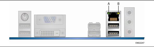
Two LEDs are built into the RJ-45 LAN connector located on the back panel (see Figure 2). These LEDs indicate the status of the LAN as shown in Table 3.
Figure 2. LAN Connector LEDs
17
Intel Desktop Board DH55PJ Product Guide
Table 3. LAN Connector LEDs
LED |
LED Color |
LED State |
Indicates |
|
|
|
|
A (Link/Activity) |
Green |
Off |
LAN link is not established |
|
|
|
|
|
|
On |
LAN link is established |
|
|
|
|
|
|
Blinking |
LAN activity is occurring |
|
|
|
|
B (Link Speed) |
N/A |
Off |
10 Mb/s data rate |
|
|
|
|
|
Green |
On |
100 Mb/s data rate |
|
|
|
|
|
Yellow |
On |
1000 Mb/s data rate |
|
|
|
|
USB 2.0 Support
The board supports up to twelve USB 2.0 ports provided by two EHCI host controllers in the PCH that allow the use of EHCI-compatible drivers.
The port arrangement is as follows:
•Six ports via stacked back panel connectors
•Six front panel ports via three dual-port internal headers
USB 2.0 support requires both an operating system and drivers that fully support USB 2.0 transfer rates.
Serial ATA Support
The board provides four internal SATA connectors through the PCH.
Expandability
Intel Desktop Board DH55PJ provides the following expansion capability:
•One PCI Express 2.0 x16 port
•Two PCI Express 2.0 x1 ports
•One PCI bus interface
18
Desktop Board Features
Legacy I/O
The board’s Legacy I/O Controller provides the following legacy features:
•One serial port header
•One parallel port header with Extended Capabilities Port (ECP) and Enhanced Parallel Port (EPP) support
•Serial IRQ interface compatible with serialized IRQ support for PCI Conventional bus systems
•PS/2-style keyboard/mouse interface
•Intelligent power management, including a programmable wake-up event interface
•PCI Conventional bus power management support
The BIOS Setup program provides configuration options for the Legacy I/O controller.
BIOS
The BIOS provides the Power-On Self-Test (POST), the BIOS Setup program, and the PCI Express and SATA auto-configuration utilities. The BIOS is stored in the Serial Peripheral Interface (SPI) Flash device.
The BIOS can be updated by following the instructions in Chapter 3 starting on page 59.
Serial ATA Auto Configuration
If you install a Serial ATA device (such as a hard drive) in your computer, the autoconfiguration utility in the BIOS automatically detects and configures the device for your computer. You do not need to run the BIOS Setup program after installing a Serial ATA device. You can override the auto-configuration options by specifying manual configuration in the BIOS Setup program.
PCI*/PCI Express Auto Configuration
If you install a PCI or PCI Express add-in card in your computer, the PCI/PCI Express auto-configuration utility in the BIOS automatically detects and configures the resources (IRQs, DMA channels, and I/O space) for that add-in card. You do not need to run the BIOS Setup program after you install a PCI or PCI Express add-in card.
19
Intel Desktop Board DH55PJ Product Guide
Security Passwords
The BIOS includes security features that restrict whether the BIOS Setup program can be accessed and who can boot the computer. A supervisor password and a user password can be set for the BIOS Setup and for booting the computer, with the following restrictions:
•The supervisor password gives unrestricted access to view and change all Setup options. If only the supervisor password is set, pressing <Enter> at the password prompt of Setup gives the user restricted access to Setup.
•If both the supervisor and user passwords are set, you must enter either the supervisor password or the user password to access Setup. Setup options are then available for viewing and changing depending on whether the supervisor or user password was entered.
•Setting a user password restricts who can boot the computer. The password prompt is displayed before the computer is booted. If only the supervisor password is set, the computer boots without asking for a password. If both passwords are set, you can enter either password to boot the computer.
For instructions on resetting the password, go to Clearing Passwords on page 51.
Hardware Management
The hardware management features of Intel Desktop Board DH55PJ enable the board to be compatible with the Wired for Management (WfM) specification. The board has several hardware management features including the following:
•Fan speed monitoring and control
•Thermal and voltage monitoring
Hardware Monitoring and Fan Speed Control
The features of the hardware monitoring and fan speed control include:
•Intel Quiet System Technology, delivering acoustically-optimized thermal management
•Thermal sensors in the processor and PCH, as well as near the CPU voltage regulators and system memory
•Monitoring of system voltages to detect levels above or below acceptable values
•Thermally monitored closed-loop fan control for all three fans that can adjust fan speed as needed
Fan Monitoring
Fan monitoring can be observed via the BIOS Setup program, Intel® Desktop Utilities, or third-party software.
20
Desktop Board Features
Power Management
Power management is implemented at several levels, including software support through the Advanced Configuration and Power Interface (ACPI) and the following hardware support:
•Power connectors
•Fan headers
•LAN wake capabilities
•Instantly Available PC technology (Suspend to RAM)
•+5 V standby power indicator LED
•Wake from USB
•PCI Power Management Event signal (PME#) wakeup support
•PCI Express WAKE# signal support
•Wake from PS/2 devices
•Wake from serial port
Software Support
ACPI
ACPI gives the operating system direct control over the power management and Plug and Play functions of a computer. The use of ACPI with the Desktop Board requires an operating system that provides full ACPI support.
Hardware Support
Power Connectors
ATX12V-compliant power supplies can turn off the computer power through system control. When an ACPI-enabled computer receives the correct command, the power supply removes all non-standby voltages.
When resuming from an AC power failure, the computer returns to the power state it was in before power was interrupted (either on or off). The computer’s response can be set by using the Last Power State feature in the BIOS Setup program’s Boot menu.
The Desktop Board has two power connectors. See Figure 23 on page 49 for the location of the power connectors.
Fan Headers
The function/operation of the fans is as follows:
•The fans are on when the board is in the ACPI S0 or S1 state.
•The fans are off when the computer is in the ACPI S3, S4, or S5 state.
•Each fan header is wired to a tachometer input.
•All fan headers support closed-loop fan control that can adjust the fan speed or switch the fan on or off as needed.
21
Intel Desktop Board DH55PJ Product Guide
•All fan headers have a +12 V DC connection (up to 12 V DC when using 3-wire chassis fans.
•All fan headers are controlled by Pulse Width Modulation.
•The front and rear chassis fans support Linear Fan Control on 3-wire fans.
The Desktop Board has a 4-pin processor fan header and two 4-pin chassis fan headers compatible with 4-wire and 3-wire chassis fans.
LAN Wake Capabilities
 CAUTION
For LAN wake capabilities, the 5 V standby line for the power supply must be capable of delivering adequate +5 V standby current. Failure to provide adequate standby current when using this feature can damage the power supply.
LAN wakeup capabilities enable remote wake-up of the computer through a network. The LAN subsystem monitors network traffic and upon detecting a Magic Packet* frame, it asserts a wake-up signal that powers up the computer.
Instantly Available PC Technology
 CAUTION
For Instantly Available PC technology, the 5 V standby line for the power supply must be capable of delivering adequate +5 V standby current. Failure to provide adequate standby current when using this feature can damage the power supply and/or effect ACPI S3 sleep state functionality.
Instantly Available PC technology enables the board to enter the ACPI S3 (Suspend-to- RAM) sleep state. Instantly Available PC technology enables the board to enter the ACPI S3 (Suspend-to-RAM) sleep-state. While in the S3 sleep-state, the computer will appear to be off (the power supply is off and the front panel power LED will behave as configured by the BIOS “S3 State Indicator” option). When signaled by a wake-up device or event, the system quickly returns to its last known wake state. When signaled by a wake-up device or event, the computer quickly returns to its last known awake state.
The Desktop Board supports the PCI Bus Power Management Interface Specification. Add-in cards that support this specification can participate in power management and can be used to wake the computer.
The use of Instantly Available PC technology requires operating system support and PCI 2.2 compliant add-in cards, PCI Express add-in cards, and drivers.
22
Desktop Board Features
+5 V Standby Power Indicator LED
 CAUTION
If the AC power has been switched off and the standby power indicator is still lit, disconnect the power cord before installing or removing any devices connected to the board. Failure to do so could damage the board and any attached devices.
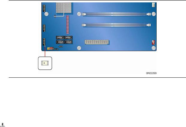
The Desktop Board’s standby power indicator, shown in Figure 3, is lit when there is standby power still present on the board even when the computer appears to be off. For example, when this green LED is lit, standby power is still present at the memory module sockets and the PCI bus connectors.
Figure 3. Location of the Standby Power Indicator
For more information on standby current requirements for the Desktop Board, refer to the Technical Product Specification at http://support.intel.com/support/motherboards/desktop/
Wake from USB
 NOTE
NOTE
Wake from USB requires the use of a USB peripheral that supports Wake from USB and an operating system that supports Wake from USB.
USB bus activity wakes the computer from an ACPI S1 or S3 state.
PCI PME# Signal Wake-up Support
When the PME# signal on the PCI bus is asserted, the computer wakes from an ACPI S1, S3, S4, or S5 state.
23
Loading...