


 Loading...
Intel® Ethernet Adapters and Devices
User Guide

Overview
Welcometothe User's Guide forIntel® Ethernet Adapters anddevices. This guidecovers hardwareand softwareinstallation, setupprocedures, andtroubleshootingtips forIntel network adapters, connections, and otherdevices.
Installing the Network Adapter
If youareinstallinganetwork adapter, follow this procedurefrom step1.
If youareupgradingthedriversoftware, start withstep5 .
NOTE: If youupdatethefirmware, youmust updatethedriversoftwaretothesamefamily version.
1.Makesurethat youareinstallingthelatest driversoftwareforyouradapter. Visit Intel's support web- site todownloadthelatest drivers.
2.Review system requirements.
3.Insert theadapter(s)inthecomputer.
4.Attachthe copper or fiber network cable(s).
5.Install thedriver.
6.ForWindows systems, install the Intel® PROSet software.
If youhaveany problems withbasic installation, see Troubleshooting.
Youcannow set upadvancedfeatures, if necessary. Theavailablefeatures andtheconfigurationprocess varies withtheadapterandyouroperatingsystem.
Before You Begin
Supported Devices
Forhelpidentifyingyournetwork deviceandfindingsupporteddevices, click thelink below:
http://www.intel.com/support
Compatibility Notes
InorderforanadapterbasedontheXL710controllertoreachits full potential, youmust install it inaPCIe Gen3x8slot. Installingit inashorterslot, oraGen2orGen1slot, will limit thethroughput of theadapter.
SomeolderIntel® Ethernet Adapters donot havefull softwaresupport forthemost recent versions of Microsoft Windows*. Many olderIntel Ethernet Adapters havebasedrivers suppliedby Microsoft Windows. Lists of supporteddevices perOS areavailableat http://www.intel.com/support/go/network/adapter/nicoscomp.htm
Supported Operating Systems
Supported 32-bit Operating Systems
NOTE: Microsoft* Windows* 32-bit operatingsystems areonly supportedonIntel 1GbE Ethernet Adapters andslowerdevices. All adapters support 32-bit versions of Linux* andFreeBSD*.
Basic softwareanddrivers aresupportedonthefollowingoperatingsystems:

•DOS
•SunSoft* Solaris* (drivers andsupport areprovidedby theoperatingsystem vendor)
Advancedsoftwareanddrivers aresupportedonthefollowingoperatingsystems:
•Microsoft Windows 7
•Microsoft Windows 8.1
•Microsoft Windows 10
•Linux*, v2.4kernel orhigher
•FreeBSD*
Supported Intel® 64 Architecture Operating Systems
•Microsoft* Windows* 7
•Microsoft Windows 8.1
•Microsoft Windows 10
•Microsoft* Windows Server* 2008R2
•Microsoft Windows Server2012
•Microsoft Windows Server2012R2
•Microsoft Windows Server2016
•Microsoft Windows Server2016NanoServer
•VMWareESXi 5.5
•VMWare* ESXi* 6.0
•VMWareESXi 6.5U1‡
•Ubuntu14.04
•RedHat* Linux*
•Novell* SUSE* Linux
•FreeBSD*
‡If youupgradetoVMWareESXi 6.5U1orlater, youmust usenativemodedrivers (availableinthelatest driversoftwarepackage)insteadof VMKLinux legacy modedrivers.
Supported Operating Systems for Itanium-based Systems
• Linux, v2.x kernel andhigher, except v2.6
SomeolderIntel® Ethernet Adapters donot havefull softwaresupport forthemost recent versions of Microsoft Windows*. Many olderIntel Ethernet Adapters havebasedrivers suppliedby Microsoft Windows. Lists of supporteddevices perOS areavailableat http://www.intel.com/support/go/network/adapter/nicoscomp.htm
Hardware Compatibility
Beforeinstallingtheadapter, check yoursystem forthefollowing:
•Thelatest BIOS foryoursystem
•OneopenPCI Express slot
NOTE: TheIntel® 10Gigabit AT ServerAdapterwill only fit intox8orlargerPCI Express slots.

Somesystems havephysical x8PCI Express slots that actually support lowerspeeds. Please check yoursystem manual toidentify theslot.
Cabling Requirements
Intel Gigabit Adapters
Fiber Optic Cables
• |
Laserwavelength: 850nanometer(not visible). |
• |
SC Cabletype: |
|
• Multi-modefiberwith50microncorediameter; maximum lengthis 550meters. |
|
• Multi-modefiberwith62.5microncorediameter; maximum lengthis 275meters. |
|
• Connectortype: SC. |
• |
LC Cabletype: |
•Multi-modefiberwith50microncorediameter; maximum lengthis 550meters.
•Multi-modefiberwith62.5microncorediameter; maximum lengthis 275meters.
•Connectortype: LC.
Copper Cables
• 1000BASE-T or100BASE-TX onCategory 5orCategory 5ewiring, twisted4-paircopper:
•MakesureyouuseCategory 5cablingthat complies withtheTIA-568wiringspecification. For moreinformationonthis specification, seetheTelecommunications Industry Association's web site: www.tiaonline.org.
•Maximum Lengthis 100meters.
•Category 3wiringsupports only 10Mbps.
NOTE: ToinsurecompliancewithCISPR 24andtheEU’s EN55024, devices basedonthe82576 controllershouldbeusedonly withCAT 5E shieldedcables that areproperly terminatedaccording totherecommendations inEN50174-2.
Intel 10 Gigabit Adapters
Fiber Optic Cables
• |
Laserwavelength: 850nanometer(not visible). |
• |
SC Cabletype: |
|
• Multi-modefiberwith50microncorediameter; maximum lengthis 550meters. |
|
• Multi-modefiberwith62.5microncorediameter; maximum lengthis 275meters. |
|
• Connectortype: SC. |
• |
LC Cabletype: |
•Multi-modefiberwith50microncorediameter; maximum lengthis 550meters.
•Multi-modefiberwith62.5microncorediameter; maximum lengthis 275meters.
•Connectortype: LC.
Copper Cables
•Maximum lengths forIntel® 10Gigabit ServerAdapters andConnections that use10GBASE-T onCategory 6, Category 6a, orCategory 7wiring, twisted4-paircopper:
•Maximum lengthforCategory 6is 55meters.
•Maximum lengthforCategory 6ais 100meters.
•Maximum lengthforCategory 7is 100meters.
•ToensurecompliancewithCISPR 24andtheEU's EN55024, Intel® 10Gigabit Server Adapters andConnections shouldbeusedonly withCAT 6ashieldedcables that areproperly terminatedaccordingtotherecommendations inEN50174-2.
• 10Gigabit Ethernet overSFP+ Direct AttachedCable(Twinaxial) • Lengthis 10meters max.
Intel 40 Gigabit Adapters
Fiber Optic Cables
• |
Laserwavelength: 850nanometer(not visible). |
• |
SC Cabletype: |
|
• Multi-modefiberwith50microncorediameter; maximum lengthis 550meters. |
|
• Multi-modefiberwith62.5microncorediameter; maximum lengthis 275meters. |
|
• Connectortype: SC. |
• |
LC Cabletype: |
•Multi-modefiberwith50microncorediameter; maximum lengthis 550meters.
•Multi-modefiberwith62.5microncorediameter; maximum lengthis 275meters.
•Connectortype: LC.
Copper Cables
• 40Gigabit Ethernet overSFP+ Direct AttachedCable(Twinaxial)
• Lengthis 7meters max
Installation Overview
Installing the Adapter
1.Turnoff thecomputerandunplugthepowercord.
2.Removethecomputercoverandtheadapterslot coverfrom theslot that matches youradapter.
3.Insert theadapteredgeconnectorintotheslot andsecurethebracket tothechassis.
4.Replacethecomputercover, thenpluginthepowercord.
Install Drivers and Software
Windows* Operating Systems
Youmust haveadministrativerights totheoperatingsystem toinstall thedrivers.
1.Downloadthelatest drivers from the support website andtransferthem tothesystem.
2.If theFoundNew HardwareWizardscreenis displayed, click Cancel.

3.Start theautorunlocatedinthedownloadedthesoftwarepackage. Theautorunmay automatically start afteryouhaveextractedthefiles.
4.Click Install Drivers and Software.
5.Follow theinstructions intheinstall wizard.
Installing Linux* Drivers from Source Code
1.Downloadandexpandthebasedrivertarfile.
2.Compilethedrivermodule.
3.Install themoduleusingthemodprobecommand.
4.AssignanIP address usingtheifconfigcommand.
Optimizing Performance
YoucanconfigureIntel network adapteradvancedsettings tohelpoptimizeserverperformance.
Theexamples below provideguidanceforthreeserverusagemodels:
•Optimizedforquick responseandlow latency – useful forvideo, audio, andHighPerformanceComputingCluster(HPCC)servers
•Optimizedforthroughput – useful fordatabackup/retrieval andfileservers
•OptimizedforCPU utilization – useful forapplication, web, mail, anddatabaseservers
NOTES:
•Therecommendations below areguidelines andshouldbetreatedas such. Additional factors suchas installedapplications, bus type, network topology, andoperatingsystem alsoaffect system performance.
•Theseadjustments shouldbeperformedby ahighly skillednetwork administrator. They are not guaranteedtoimproveperformance. Not all settings shownheremay beavailable throughnetwork driverconfiguration, operatingsystem orsystem BIOS. Linux users, seethe README fileintheLinux driverpackageforLinux-specific performanceenhancement details.
•Whenusingperformancetest software, refertothedocumentationof theapplicationfor optimal results.
General Optimization
• Install theadapterinanappropriateslot.
NOTE: SomePCIex8slots areactually configuredas x4slots. Theseslots haveinsufficient bandwidthforfull lineratewithsomedual port devices. Thedrivercandetect this situation andwill writethefollowingmessageinthesystem log: “PCI-Express bandwidthavailablefor this cardis not sufficient foroptimal performance. Foroptimal performanceax8PCIExpress slot is required.”If this erroroccurs, movingyouradaptertoatruex8slot will resolve theissue.
•InorderforanIntel® X710/XL710basedNetwork Adaptertoreachits full potential, youmust install it inaPCIeGen3x8slot. Installingit inashorterslot, oraGen2orGen1slot, will impact thethroughput theadaptercanattain.
•Usethepropercablingforyourdevice.
•EnableJumboPackets, if yourothernetwork components canalsobeconfiguredforit.
•Increasethenumberof TCP andSocket resources from thedefault value. ForWindows basedsystems, wehavenot identifiedsystem parameters otherthantheTCP Window Sizewhichsignificantly impact performance.
•Increasetheallocationsizeof DriverResources (transmit/receivebuffers). However, most TCP traffic patterns work best withthetransmit bufferset toits default value, andthereceivebufferset toits minimum value.
•Whenpassingtraffic onmultiplenetwork ports usinganI/Oapplicationthat runs onmost orall of the cores inyoursystem, considersettingtheCPU Affinity forthat applicationtofewercores. This should reduceCPU utilizationandinsomecases may increasethroughput forthedevice. Thecores selected forCPU Affinity must belocal totheaffectednetwork device's ProcessorNode/Group. Youcanuse thePowerShell commandGet-NetAdapterRSS tolist thecores that arelocal toadevice. Youmay needtoincreasethenumberof cores assignedtotheapplicationtomaximizethroughput. Refertoyour operatingsystem documentationformoredetails onsettingtheCPU Affinity.
•If youhavemultiple10Gpbs (orfaster)ports installedinasystem, theRSS queues of eachadapter port canbeadjustedtousenon-overlappingsets of processors withintheadapter's local NUMA Node/Socket. ChangetheRSS BaseProcessorNumberforeachadapterport sothat thecombination of thebaseprocessorandthemax numberof RSS processors settings ensurenon-overlappingcores.
1.Identify theadapterports tobeadjustedandinspect at theirRssProcessorArray usingthe Get-NetAdapterRSS PowerShell cmdlet.
2.Identify theprocessors withNUMA distance0. Thesearethecores intheadapter's local NUMA Node/Socket andwill providethebest performance.
3.Adjust theRSS Baseprocessoroneachport touseanon-overlappingset of processors within thelocal set of processors. Youcandothis manually orusingthefollowingPowerShell command:
Set-NetAdapterAdvancedProperty -Name <Adapter Name> -DisplayName "RSS Base
Processor Number" -DisplayValue <RSS Base Proc Value>
4.UsetheGet-NetAdpaterAdvancedproperty cmdlet tocheck that theright values havebeenset:
Get-NetAdpaterAdvancedproperty -Name <Adapter Name>
ForExample: Fora4port adapterwithLocal processors 0, 2, 4, 6, 8, 10, 12, 14, 16, 18, 20, 22, 24, 26, 28, 30, and'Max RSS processor' of 8, set theRSS baseprocessors to0, 8, 16and24.
Optimized for quick response and low latency
•MinimizeordisableInterrupt ModerationRate.
•DisableOffloadTCP Segmentation.
•DisableJumboPackets.
•IncreaseTransmit Descriptors.
•IncreaseReceiveDescriptors.
•IncreaseRSS Queues.

Optimized for throughput
•EnableJumboPackets.
•IncreaseTransmit Descriptors.
•IncreaseReceiveDescriptors.
•Onsystems that support NUMA, set thePreferredNUMA Nodeoneachadaptertoachievebetterscalingacross NUMA nodes.
Optimized for CPU utilization
•MaximizeInterrupt ModerationRate.
•Keepthedefault settingforthenumberof ReceiveDescriptors; avoidsettinglargenumbers of Receive Descriptors.
•DecreaseRSS Queues.
•InHyper-V environments, decreasetheMax numberof RSS CPUs.
Remote Storage
Theremotestoragefeatures allow youtoaccess aSAN orothernetworkedstorageusingEthernet protocols. This includes DataCenterBridging(DCB), iSCSI overDCB, andFibreChannel overEthernet (FCoE).
DCB (Data Center Bridging)
DataCenterBridging(DCB)is acollectionof standards-basedextensions toclassical Ethernet. It provides a lossless datacentertransport layerthat enables theconvergenceof LANs andSANs ontoasingleunified fabric.
Furthermore, DCB is aconfigurationQuality of Serviceimplementationinhardware. It uses theVLAN priority tag(802.1p)tofiltertraffic. That means that thereare8different priorities that traffic canbefilteredinto. It also enables priority flow control (802.1Qbb)whichcanlimit oreliminatethenumberof droppedpackets during network stress. Bandwidthcanbeallocatedtoeachof thesepriorities, whichis enforcedat thehardwarelevel (802.1Qaz).
Adapterfirmwareimplements LLDP andDCBX protocol agents as per802.1AB and802.1Qaz respectively. ThefirmwarebasedDCBX agent runs inwillingmodeonly andcanaccept settings from aDCBX capable peer. Softwareconfigurationof DCBX parameters viadcbtool/lldptool arenot supported.
iSCSI Over DCB
Intel® Ethernet adapters support iSCSI softwareinitiators that arenativetotheunderlyingoperatingsystem. Inthecaseof Windows, theMicrosoft iSCSI SoftwareInitiator, enables connectionof aWindows host toan external iSCSI storagearray usinganIntel Ethernet adapter.
Inthecaseof OpenSourcedistributions, virtually all distributions includesupport foranOpeniSCSI Software InitiatorandIntel® Ethernet adapters will support them. Pleaseconsult yourdistributiondocumentationfor additional configurationdetails ontheirparticularOpeniSCSI initiator.

Intel® 82599andX540-basedadapters support iSCSI withinaDataCenterBridgingcloud. Usedin conjunctionwithswitches andtargets that support theiSCSI/DCB applicationTLV, this solutioncanprovide guaranteedminimum bandwidthforiSCSI traffic betweenthehost andtarget. This solutionenables storage administrators tosegment iSCSI traffic from LAN traffic, similartohow they cancurrently segment FCoE from LAN traffic. Previously, iSCSI traffic withinaDCB supportedenvironment was treatedas LAN traffic by switchvendors. Pleaseconsult yourswitchandtarget vendors toensurethat they support theiSCSI/DCB applicationTLV.
Intel® Ethernet FCoE (Fibre Channel over Ethernet)
FibreChannel overEthernet (FCoE)is theencapsulationof standardFibreChannel (FC)protocol frames as datawithinstandardEthernet frames. This link-level encapsulation, teamedwithanFCoE-awareEthernet-to- FC gateway, acts toextendanFC fabric toincludeEthernet-basedhost connectivity. TheFCoE specification focuses onencapsulationof FC frames specific tostorageclass traffic, as definedby theFibreChannel FC-4 FCP specification.
NOTE: Support fornew operatingsystems will not beaddedtoFCoE. Thelast operatingsystem versions that support FCoE areas follows:
•Microsoft* Windows Server* 2012R2
•RHEL7.2
•RHEL6.7
•SLES 12SP1
•SLES 11SP4
•VMware* ESX 6.0U3
Jumbo Frames
Thebasedriversupports FCoE mini-JumboFrames (2.5k bytes)independent of theLAN JumboFrames setting.
FCoE VN to VN (VN2VN) Support
FCoE VN toVN, alsocalledVN2VN, is astandardforconnectingtwoend-nodes (ENodes)directly using FCoE. AnENodecancreateaVN2VN virtual link withanotherremoteENodeby not connectingtoFC or FCoE switches (FCFs)inbetween, soneitherport zoningnoradvancefibrechannel services is required. The storagesoftwarecontrols access to, andsecurity of, LUNs usingLUN masking. TheVN2VN fabric may have alossless Ethernet switchbetweentheENodes. This allows multipleENodes toparticipateincreatingmore thanoneVN2VN virtual link intheVN2VN fabric. VN2VN has twooperational modes: Point toPoint (PT2PT) andMultipoint.
NOTE: Themodeof operationis usedonly duringinitialization.
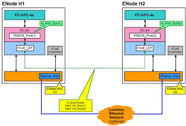
Point to Point (PT2PT) Mode
InPoint toPoint mode, thereareonly twoENodes, andthey areconnectedeitherdirectly orthrougha lossless Ethernet switch:

MultiPoint Mode
If morethantwoENodes aredetectedintheVN2VN fabric, thenall nodes shouldoperateinMultipoint mode:
Enabling VN2VN in Microsoft Windows
ToenableVN2VN inMicrosoft Windows:
1.Start Windows DeviceManager.
2.OpentheappropriateFCoE miniport property sheet (generally underStoragecontrollers)andclick on theAdvancedtab.
3.Select theVN2VN settingandchoose"Enable."
Remote Boot
RemoteBoot allows youtoboot asystem usingonly anEthernet adapter. Youconnect toaserverthat contains anoperatingsystem imageandusethat toboot yourlocal system.
Intel® Boot Agent
TheIntel® Boot Agent is asoftwareproduct that allows yournetworkedclient computertoboot usinga program codeimagesuppliedby aremoteserver. Intel Boot Agent complies withthePre-boot eXecution Environment (PXE)Version2.1Specification. It is compatiblewithlegacy boot agent environments that use BOOTP protocol.
Supported Devices
Intel Boot Agent supports all Intel 10Gigabit Ethernet, 1Gigabit Ethernet, andPRO/100Ethernet Adapters.

Intel® Ethernet iSCSI Boot
Intel® Ethernet iSCSI Boot provides thecapability toboot aclient system from aremoteiSCSI disk volume locatedonaniSCSI-basedStorageAreaNetwork (SAN).
NOTE: Release20.6is thelast releaseinwhichIntel® Ethernet iSCSI Boot supports Intel® Ethernet DesktopAdapters andNetwork Connections. StartingwithRelease20.7, Intel Ethernet iSCSI Boot nolongersupports Intel Ethernet DesktopAdapters andNetwork Connections.
Intel® Ethernet FCoE Boot
Intel® Ethernet FCoE Boot provides thecapability toboot aclient system from aremotedisk volumelocated onanFibreChannel StorageAreaNetwork (SAN).
Using Intel® PROSet for Windows Device Manager
Therearetwoways tonavigatetotheFCoE properties inWindows DeviceManager: by usingthe"Data Center" tabontheadapterproperty sheet orby usingtheIntel® "Ethernet Virtual StorageMiniport Driverfor FCoE StorageControllers" property sheet.
Supported Devices
A list of Intel Ethernet Adapters that support FCoE canbefoundat
http://www.intel.com/support/go/network/adapter/fcoefaq.htm
Virtualization Support
Virtualizationmakes it possibleforoneormoreoperatingsystems torunsimultaneously onthesamephysical system as virtual machines. This allows youtoconsolidateseveral servers ontoonesystem, evenif they are runningdifferent operatingsystems. Intel® Network Adapters work with, andwithin, virtual machines with theirstandarddrivers andsoftware.
NOTES:
•Somevirtualizationoptions arenot availableonsomeadapter/operatingsystem combinations.
•Thejumboframesettinginsideavirtual machinemust bethesame, orlowerthan, thesetting onthephysical port.
•WhenyouattachaVirtual Machinetoatenant overlay network throughtheVirtual NIC ports onaVirtual Switch, theencapsulationheaders increasetheMaximum TransmissionUnit (MTU)sizeonthevirtual port. TheEncapsulationOverheadfeatureautomatically adjusts the physical port's MTU sizetocompensateforthis increase.
•See http://www.intel.com/technology/advanced_comm/virtualization.htm formoreinformationonusingIntel Network Adapters invirtualizedenvironments.
Using Intel® Network Adapters in a Microsoft* Hyper-V* Environment
WhenaHyper-V Virtual NIC (VNIC)interfaceis createdintheparent partition, theVNIC takes ontheMAC address of theunderlyingphysical NIC. Thesameis truewhenaVNIC is createdonateam orVLAN. Since theVNIC uses theMAC address of theunderlyinginterface, any operationthat changes theMAC address of

theinterface(forexample, settingLAA ontheinterface, changingtheprimary adapteronateam, etc.), will causetheVNIC toloseconnectivity. Inordertoprevent this loss of connectivity, Intel® PROSet will not allow youtochangesettings that changetheMAC address.
NOTES:
•If FibreChannel overEthernet (FCoE)/DataCenterBridging(DCB)is present ontheport, configuringthedeviceinVirtual MachineQueue(VMQ)+ DCB modereduces thenumberof VMQ VPorts availableforguest OSes. This does not apply toIntel® Ethernet Controller X710baseddevices.
•Whensent from insideavirtual machine, LLDP andLACP packets may beasecurity risk. TheIntel® Virtual Functiondriverblocks thetransmissionof suchpackets.
•TheVirtualizationsettingontheAdvancedtabof theadapter's DeviceManagerproperty sheet is not availableif theHyper-V roleis not installed.
•WhileMicrosoft supports Hyper-V ontheWindows* 8.1client OS, Intel® Ethernet adapters donot support virtualizationsettings (VMQ, SR-IOV)onWindows 8.1client.
•ANS teamingof VF devices insideaWindows 2008R2guest runningonanopensource hypervisoris supported.
The Virtual Machine Switch
Thevirtual machineswitchis part of thenetwork I/Odatapath. It sits betweenthephysical NIC andthe virtual machineNICs androutes packets tothecorrect MAC address. EnablingVirtual MachineQueue(VMQ) offloadinginIntel® PROSet will automatically enableVMQ inthevirtual machineswitch. Fordriver-only installations, youmust manually enableVMQ inthevirtual machineswitch.
Using ANS VLANs
If youcreateANS VLANs intheparent partition, andyouthencreateaHyper-V Virtual NIC interfaceonan ANS VLAN, thentheVirtual NIC interface*must* havethesameVLAN ID as theANS VLAN. Usinga different VLAN ID ornot settingaVLAN ID ontheVirtual NIC interfacewill result inloss of communicationon that interface.
Virtual Switches boundtoanANS VLAN will havethesameMAC address as theVLAN, whichwill havethe sameaddress as theunderlyingNIC orteam. If youhaveseveral VLANs boundtoateam andbindavirtual switchtoeachVLAN, all of thevirtual switches will havethesameMAC address. Clusteringthevirtual switches togetherwill causeanetwork errorinMicrosoft’s clustervalidationtool. Insomecases, ignoringthis errorwill not impact theperformanceof thecluster. However, suchaclusteris not supportedby Microsoft. UsingDeviceManagertogiveeachof thevirtual switches auniqueaddress will resolvetheissue. Seethe Microsoft TechNet article ConfigureMAC Address SpoofingforVirtual Network Adapters formore information.
Virtual MachineQueues (VMQ)andSR-IOV cannot beenabledonaHyper-V Virtual NIC interfaceboundtoa VLAN configuredusingtheVLANs tabinWindows DeviceManager.
Using an ANS Team or VLAN as a Virtual NIC
If youwant touseateam orVLAN as avirtual NIC youmust follow thesesteps:

NOTES:
•This applies only tovirtual NICs createdonateam orVLAN. Virtual NICs createdona physical adapterdonot requirethesesteps.
•ReceiveLoadBalancing(RLB)is not supportedinHyper-V. DisableRLB whenusing Hyper-V.
1.UseIntel® PROSet tocreatetheteam orVLAN.
2.OpentheNetwork Control Panel.
3.Opentheteam orVLAN.
4.OntheGeneral Tab, uncheck all of theprotocol bindings andclick OK.
5.Createthevirtual NIC. (If youcheck the"Allow management operatingsystem tosharethenetwork adapter." box youcandothefollowingstepintheparent partition.)
6.OpentheNetwork Control Panel fortheVirtual NIC.
7.OntheGeneral Tab, check theprotocol bindings that youdesire.
NOTE: This stepis not requiredfortheteam. WhentheVirtual NIC is created, its protocols arecorrectly bound.
Command Line for Microsoft Windows Server* Core
Microsoft Windows Server* Coredoes not haveaGUI interface. If youwant touseanANS Team orVLAN as aVirtual NIC, youmust use Microsoft* Windows PowerShell* toset uptheconfiguration. UseWindows PowerShell tocreatetheteam orVLAN.
NOTE: Support fortheIntel PROSet commandlineutilities (prosetcl.exeandcrashdmp.exe)has beenremoved, andis nolongerinstalled. This functionality has beenreplacedby theIntel Netcmdlets forMicrosoft* Windows PowerShell*. Pleasetransitionall of yourscripts and processes tousetheIntel Netcmdlets forMicrosoft Windows PowerShell.
Thefollowingis anexampleof how toset uptheconfigurationusingMicrosoft* Windows PowerShell*.
1.Get all theadapters onthesystem andstorethem intoavariable. $a = Get-IntelNetAdapter
2.Createateam by referencingtheindexes of thestoredadapterarray.
New-IntelNetTeam -TeamMembers $a[1],$a[2] -TeamMode
VirtualMachineLoadBalancing -TeamName “Team1”
Virtual Machine Queue Offloading
EnablingVMQ offloadingincreases receiveandtransmit performance, as theadapterhardwareis ableto perform thesetasks fasterthantheoperatingsystem. Offloadingalsofrees upCPU resources. Filteringis basedonMAC and/orVLAN filters. Fordevices that support it, VMQ offloadingis enabledinthehost partition ontheadapter's DeviceManagerproperty sheet, underVirtualizationontheAdvancedTab.

EachIntel® Ethernet Adapterhas apool of virtual ports that aresplit betweenthevarious features, suchas VMQ Offloading, SR-IOV, DataCenterBridging(DCB), andFibreChannel overEthernet (FCoE). Increasing thenumberof virtual ports usedforonefeaturedecreases thenumberavailableforotherfeatures. Ondevices that support it, enablingDCB reduces thetotal pool availableforotherfeatures to32. EnablingFCoE further reduces thetotal pool to24.
NOTE: This does not apply todevices basedontheIntel® Ethernet X710orXL710controllers.
Intel PROSet displays thenumberof virtual ports availableforvirtual functions underVirtualizationproperties onthedevice's AdvancedTab. It alsoallows youtoset how theavailablevirtual ports aredistributedbetween VMQ andSR-IOV.
Teaming Considerations
•If VMQ is not enabledforall adapters inateam, VMQ will bedisabledfortheteam.
•If anadapterthat does not support VMQ is addedtoateam, VMQ will bedisabledfortheteam.
•Virtual NICs cannot becreatedonateam withReceiveLoadBalancingenabled. ReceiveLoadBalancingis automatically disabledif youcreateavirtual NIC onateam.
•If ateam is boundtoaHyper-V virtual NIC, youcannot changethePrimary orSecondary adapter.
Virtual Machine Multiple Queues
Virtual MachineMultipleQueues (VMMQ) enables ReceiveSideScaling(RSS)forvirtual ports attachedtoa physical port. This allows RSS tobeusedwithSR-IOV andinsideaVMQ virtual machine, andoffloads the RSS processingtothenetwork adapter. RSS balances receivetraffic across multipleCPUs orCPU cores. This settinghas noeffect if yoursystem has only oneprocessingunit.
SR-IOV Overview
SingleRoot IOVirtualization(SR-IOV)is aPCI SIGspecificationallowingPCI Express devices toappearas multipleseparatephysical PCI Express devices. SR-IOV allows efficient sharingof PCI devices among Virtual Machines (VMs). It manages andtransports datawithout theuseof ahypervisorby providing independent memory space, interrupts, andDMA streams foreachvirtual machine.
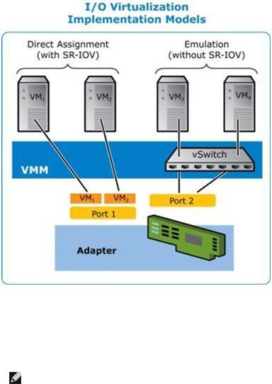
SR-IOV architectureincludes twofunctions:
•Physical Function(PF)is afull featuredPCI Express functionthat canbediscovered, managedand configuredlikeany otherPCI Express device.
•Virtual Function(VF)is similartoPF but cannot beconfiguredandonly has theability totransferdatain andout. TheVF is assignedtoaVirtual Machine.
NOTES:
•SR-IOV must beenabledintheBIOS.
•InWindows Server2012, SR-IOV is not supportedwithteamingandVLANS. This occurs becausetheHyper-V virtual switchdoes not enableSR-IOV onvirtual interfaces suchas teamingorVLANs. ToenableSR-IOV, removeall teams andVLANs.
SR-IOV Benefits
SR-IOV has theability toincreasethenumberof virtual machines supportedperphysical host, improvingI/O devicesharingamongvirtual machines forhigheroverall performance:
•Provides nearnativeperformanceduetodirect connectivity toeachVM throughavirtual function
•Preserves VM migration
•Increases VM scalability onavirtualizedserver
•Provides dataprotection

iWARP (Internet Wide Area RDMA Protocol)
RemoteDirect Memory Access, orRDMA, allows acomputertoaccess anothercomputer's memory without interactingwitheithercomputer's operatingsystem databuffers, thus increasingnetworkingspeedand throughput. Internet WideAreaRDMA Protocol (iWARP)is aprotocol forimplementingRDMA across Internet Protocol networks.
Microsoft* Windows* provides twoforms of RDMA: Network Direct (ND)andNetwork Direct Kernel (NDK). ND allows user-modeapplications touseiWARP features. NDK allows kernel modeWindows components (suchas FileManager)touseiWARP features. NDK functionality is includedintheIntel basenetworking drivers. ND functionality is aseparateoptionavailableduringIntel driverandnetworkingsoftwareinstallation. If youplantomakeuseof iWARP features inapplications youaredeveloping, youwill needtoinstall theusermodeNetwork Direct (ND)featurewhenyouinstall thedrivers. (SeeInstallationbelow.)
NOTE: EventhoughNDK functionality is includedinthebasedrivers, if youwant toallow NDK's RDMA featureacross subnets, youwill needtoselect "EnableiWARP routingacross IP Subnets" ontheiWARP ConfigurationOptions screenduringbasedriverinstallation(seeInstallationbelow).
Requirements
TheIntel® Ethernet UserModeiWARP Provideris supportedonLinux* operatingsystems andMicrosoft* Windows Server* 2012R2orlater. ForWindows installations, Microsoft HPC Pack orIntel MPI Library must beinstalled.
Installation
NOTE: ForinstallationonWindows Server2016NanoServer, seeInstallingonNanoServerbelow.
Network Direct Kernel (NDK)features areincludedintheIntel basedrivers. Follow thesteps below toinstall user-modeNetwork Direct (ND)iWARP features.
1.From theinstallationmedia, runAutorun.exetolaunchtheinstaller, thenchoose"Install Drivers and Software" andaccept thelicenseagreement.
2.OntheSetupOptions screen, select "Intel® Ethernet UserModeiWARP Provider".
3.OntheiWARP ConfigurationOptions screen, select "EnableiWARP routingacross IP Subnets" if desired. Notethat this optionis displayedduringbasedriverinstallationevenif usermodeiWARP was not selected, as this optionis applicabletoNetwork Direct Kernel functionality as well.
4.If Windows Firewall is installedandactive, select "CreateanIntel® Ethernet iWARP Port MappingServiceruleinWindows Firewall" andthenetworks towhichtoapply therule. If Windows Firewall is disabledoryouareusingathirdparty firewall, youwill needtomanually addthis rule.
5.Continuewithdriverandsoftwareinstallation.
Installing on Nano Server
Follow thesteps below toinstall theIntel® Ethernet UserModeiWARP ProvideronMicrosoft Windows Server2016NanoServer.
1.Createadirectory from whichtoinstall theiWARP files. Forexample, C:\Nano\iwarp.
2.Copy thefollowingfiles intoyournew directory:
•\Disk\APPS\PROSETDX\Winx64\DRIVERS\i40wb.dll
•\Disk\APPS\PROSETDX\Winx64\DRIVERS\i40wbmsg.dll
•\Disk\APPS\PROSETDX\Winx64\DRIVERS\indv2.cat
•\Disk\APPS\PROSETDX\Winx64\DRIVERS\indv2.inf
•\Disk\APPS\PROSETDX\Winx64\DRIVERS\indv2.sys
3.RuntheDISM commandtoinject theiWARP files intoyourNanoServerimage, usingthedirectory youcreatedinstep1fortheAddDriverpathparameter. Forexample, "DISM .../Add-DriverC:\Nan- o\iwarp"
4.Createaninboundfirewall ruleforUDP port 3935.
5.If desired, usetheWindows PowerShell commands below toenableiWARP routingacross IP Subnets.
•Set-NetOffloadGlobalSetting -NetworkDirectAcrossIPSubnets Allow
•DisableAdapter
•EnableAdapter
Customer Support
•MainIntel websupport site: http://support.intel.com
•Network products information: http://www.intel.com/network
Legal / Disclaimers
Copyright (C)2016, Intel Corporation. All rights reserved.
Intel Corporationassumes noresponsibility forerrors oromissions inthis document. Nordoes Intel makeany commitment toupdatetheinformationcontainedherein.
Intel is atrademark of Intel CorporationintheU.S. and/orothercountries.
*Othernames andbrands may beclaimedas theproperty of others.
This softwareis furnishedunderlicenseandmay only beusedorcopiedinaccordancewiththeterms of the license. Theinformationinthis manual is furnishedforinformational useonly, is subject tochangewithout notice, andshouldnot beconstruedas acommitment by Intel Corporation. Intel Corporationassumes no responsibility orliability
forany errors orinaccuracies that may appearinthis document orany softwarethat may beprovidedin associationwiththis document. Except as permittedby suchlicense, nopart of this document may be reproduced, storedinaretrieval system, ortransmittedinany form orby any means without theexpress writtenconsent of Intel Corporation.
Installing the Adapter
Select the Correct Slot
OneopenPCI-Express slot, x4, x8, orx16, dependingonyouradapter.
NOTE: Somesystems havephysical x8PCI Express slots that actually only support lowerspeeds. Pleasecheck yoursystem manual toidentify theslot.
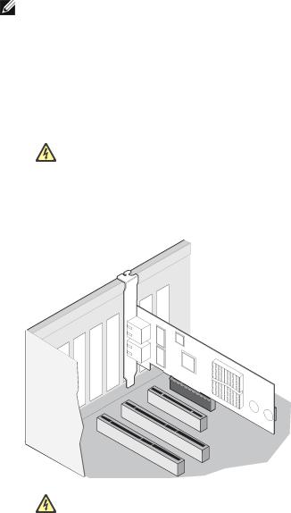
Insert the Adapter into the Computer
1.If yourcomputersupports PCI Hot Plug, seeyourcomputerdocumentationforspecial installation instructions.
2.Turnoff andunplugyourcomputer. Thenremovethecover.
CAUTION: Turnoff andunplugthepowerbeforeremovingthecomputer's cover. Failureto dosocouldendangeryouandmay damagetheadapterorcomputer.
3.Removethecoverbracket from anavailableslot.
4.Insert theadapter, pushingit intotheslot until theadapteris firmly seated. Youcaninstall asmaller PCI Express adapterinalargerPCI Express slot.
CAUTION: SomePCI Express adapters may haveashort connector, makingthem morefragilethanPCI adapters. Excessiveforcecouldbreak theconnector. Usecautionwhenpressingtheboardintheslot.
5.Securetheadapterbracket withascrew, if required.
6.Replacethecomputercoverandpluginthepowercord.
7.Poweronthecomputer.
Connecting Network Cables
Connect theappropriatenetwork cable, as describedinthefollowingsections.
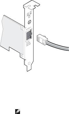
Connect the RJ-45 Network Cable
Connect theRJ-45network cableas shown:
Typeof cablingtouse:
• 10GBASE-T onCategory 6, Category 6a, orCategory 7wiring, twisted4-paircopper:
•Lengthis 55meters max forCategory 6.
•Lengthis 100meters max forCategory 6a.
•Lengthis 100meters max forCategory 7.
NOTE: FortheIntel® 10Gigabit AT ServerAdapter, toensurecompliancewithCISPR 24 andtheEU’s EN55024, this product shouldbeusedonly withCategory 6ashieldedcables that areproperly terminatedaccordingtotherecommendations inEN50174-2.
• For1000BASE-T or100BASE-TX, useCategory 5orCategory 5ewiring, twisted4-paircopper:
•MakesureyouuseCategory 5cablingthat complies withtheTIA-568wiringspecification. For moreinformationonthis specification, seetheTelecommunications Industry Association's web site: www.tiaonline.org.
•Lengthis 100meters max.
•Category 3wiringsupports only 10Mbps.
CAUTION: If using less than 4-pair cabling, you must manually configure the speed and duplex setting of the adapter and the link partner. In addition, with 2- and 3-pair cabling the adapter can only achieve speeds of up to 100Mbps.
•For100BASE-TX, useCategory 5wiring.
•For10Base-T, useCategory 3or5wiring.
•If youwant tousethis adapterinaresidential environment (at any speed), useCategory 5wiring. If the cableruns betweenrooms orthroughwalls and/orceilings, it shouldbeplenum-ratedforfiresafety.
Inall cases:
•Theadaptermust beconnectedtoacompatiblelink partner, preferably set toauto-negotiatespeedand duplex forIntel gigabit adapters.
•Intel Gigabit and10Gigabit ServerAdapters usingcopperconnections automatically accommodate eitherMDI orMDI-X connections. Theauto-MDI-X featureof Intel gigabit copperadapters allows you todirectly connect twoadapters without usingacross-overcable.
Connect the Fiber Optic Network Cable
CAUTION: The fiber optic ports contain a Class 1 laser device. When the ports are disconnected, always cover them with the provided plug. If an abnormal fault occurs, skin or eye damage may result if in close proximity to the exposed ports.
Removeandsavethefiberoptic connectorcover. Insert afiberoptic cableintotheports onthenetwork adapterbracket as shownbelow.
Most connectors andports arekeyedforproperorientation. If thecableyouareusingis not keyed, check to besuretheconnectoris orientedproperly (transmit port connectedtoreceiveport onthelink partner, andvice versa).
Theadaptermust beconnectedtoacompatiblelink partneroperatingat thesamelaserwavelengthas the adapter.
Conversioncables tootherconnectortypes (suchas SC-to-LC)may beusedif thecablingmatches the optical specifications of theadapter, includinglengthlimitations.
Insert thefiberoptic cableas shownbelow.
Connection requirements
• 40GBASE-SR4/MPO on850nanometeroptical fiber:
•Utilizing50/125micronOM3, lengthis 100meters max.
•Utilizing50/125micronOM4, lengthis 150meters max.
• 25GBASE--SR/LC on850nanometeroptical fiber:
•Utilizing50micronmultimode, lengthis 300meters max.
•Utilizing62.5micronmultimode, lengthis 33meters max.

• 10GBASE-SR/LC on850nanometeroptical fiber:
•Utilizing50micronmultimode, lengthis 300meters max.
•Utilizing62.5micronmultimode, lengthis 33meters max.
• 1000BASE-SX/LC on850nanometeroptical fiber:
•Utilizing50micronmultimode, lengthis 550meters max.
•Utilizing62.5micronmultimode, lengthis 275meters max.
Supported SFP+ and QSFP+ Modules
Adapters Based on the 710 Series of Controllers
Forinformationonsupportedmedia, seethefollowinglink:
http://www.intel.com/content/dam/www/public/us/en/documents/release-notes/xl710-ethernet-controller- feature-matrix.pdf
NOTES:
•SomeIntel brandednetwork adapters basedontheX710/XL710controlleronly support Intel brandedmodules. Ontheseadapters, othermodules arenot supportedandwill not function.
•Forconnections basedonthe710series of controllers, support is dependent onyoursystem board. Pleaseseeyourvendorfordetails.
•Inall cases Intel recommends usingIntel optics; othermodules may functionbut arenot validatedby Intel. Contact Intel forsupportedmediatypes.
•Insystems that donot haveadequateairflow tocool theadapterandoptical modules, you must usehightemperatureoptical modules.
•ForXXV710basedSFP+ adapters Intel recommends usingIntel optics andcables. Other modules may functionbut arenot validatedby Intel. Contact Intel forsupportedmediatypes.
82599-Based Adapters
NOTES:
•If your82599-basedIntel® Network AdaptercamewithIntel optics, oris anIntel® Ethernet ServerAdapterX520-2, thenit only supports Intel optics and/orthedirect attachcables listed below.
•82599-Basedadapters support all passiveandactivelimitingdirect attachcables that comply withSFF-8431v4.1andSFF-8472v10.4specifications.
|
Supplier |
|
Type |
|
Part Numbers |
|
|
|
|
|
|||
|
|
|
|
|
|
|
|
SR Modules |
|
|
|
|
|
|
|
|
|
|
|
|
|
Intel |
|
DUALRATE 1G/10G SFP+ SR (bailed) |
|
AFBR-703SDZ- |
|
|
|
|
|
|
IN2 |
|
|
|
|
|
|
|
|
|
Intel |
|
DUALRATE 1G/10G SFP+ SR (bailed) |
|
FTLX8571D3BCV- |
|
|
|
|
|
|
|
|
|
|
|
|
|
|
|
|
|
|
|
|
|
|
|
|
IT |
|
|
|
|
|
|
|
|
|
|
|
|
|
|
|
|
|
|
|
|
|
|
|
|
Intel |
|
DUALRATE 1G/10G SFP+ SR (bailed) |
|
|
|
|
AFBR-703SDDZ- |
|
|
|
|
|
|
|
|
|
|
|
IN1 |
|
|
|
|
|
|
|
|
|
|
|
|
|
LR Modules |
|
|
|
|
|
|
|
|
|
|
|
|
|
|
|
|
|
|
|
|
|
Intel |
|
DUALRATE 1G/10G SFP+ LR (bailed) |
|
|
|
|
FTLX1471D3BCV- |
|
|
|
|
|
|
|
|
|
|
|
IT |
|
|
|
|
|
|
|
|
|
|
|
|
|
Intel |
|
DUALRATE 1G/10G SFP+ LR (bailed) |
|
|
|
|
AFCT-701SDZ- |
|
|
|
|
|
|
|
|
|
|
|
IN2 |
|
|
|
|
|
|
|
|
|
|
|
|
|
Intel |
|
DUALRATE 1G/10G SFP+ LR (bailed) |
|
|
|
|
AFCT-701SDDZ- |
|
|
|
|
|
|
|
|
|
|
|
IN1 |
|
|
|
|
|
|
|
|
|
|
|
|
|
QSFP Mod- |
|
|
|
|
|
|
|
|
|
|
ules |
|
|
|
|
|
|
|
|
|
|
|
|
|
|
|
|
|
|
|
|
|
Intel |
|
TRIPLE RATE 1G/10G/40G QSFP+ SR (bailed)(40G not sup- |
E40GQSFPSR |
|
|||||
|
|
|
|
portedon82599) |
|
|
|
|
|
|
|
|
|
|
|
|
|
|
|
||
|
|
|
|
|
|
|||||
Thefollowingis alist of 3rdparty SFP+ modules that havereceivedsometesting. Not all modules are |
|
|||||||||
applicabletoall devices. |
|
|
|
|
|
|
||||
|
Supplier |
|
Type |
|
Part Numbers |
|
|
|
||
|
|
|
|
|
|
|||||
|
|
|
|
|
|
|
|
|
|
|
|
Finisar |
|
SFP+ SR bailed, 10G singlerate |
|
FTLX8571D3BCL |
|
|
|
||
|
|
|
|
|
|
|
|
|
|
|
|
Avago |
|
SFP+ SR bailed, 10G singlerate |
|
AFBR-700SDZ |
|
|
|
||
|
|
|
|
|
|
|
|
|
|
|
|
Finisar |
|
SFP+ LR bailed, 10G singlerate |
|
FTLX1471D3BCL |
|
|
|
||
|
|
|
|
|
|
|
|
|
|
|
|
|
|
|
|
|
|
|
|
|
|
|
Finisar |
|
DUALRATE 1G/10G SFP+ SR (NoBail) |
|
FTLX8571D3QCV-IT |
|
|
|
||
|
|
|
|
|
|
|
|
|
|
|
|
Avago |
|
DUALRATE 1G/10G SFP+ SR (NoBail) |
|
AFBR-703SDZ-IN1 |
|
|
|
||
|
|
|
|
|
|
|
|
|
|
|
|
Finisar |
|
DUALRATE 1G/10G SFP+ LR (NoBail) |
|
FTLX1471D3QCV-IT |
|
|
|
||
|
|
|
|
|
|
|
|
|
|
|
|
Avago |
|
DUALRATE 1G/10G SFP+ LR (NoBail) |
|
AFCT-701SDZ-IN1 |
|
|
|
||
|
|
|
|
|
|
|
|
|
|
|
|
|
|
|
|
|
|
|
|
|
|
|
Finisar |
|
1000BASE-T SFP |
|
FCLF8522P2BTL |
|
|
|
||
|
|
|
|
|
|
|
|
|
|
|
|
|
|
|
|
|
|
|
|
|
|

|
Avago |
|
1000BASE-T SFP |
|
ABCU-5710RZ |
|
|
|
|
|
|||
|
|
|
|
|
|
|
|
|
|
|
|
|
|
|
HP |
|
1000BASE-SX SFP |
|
453153-001 |
|
|
|
|
|
|
|
|
|
|
|
|
|
|
|
82598-Based Adapters
NOTES:
•Intel® Network Adapters that support removableoptical modules only support theiroriginal moduletype(i.e., theIntel® 10Gigabit SR Dual Port Express Moduleonly supports SR optical modules). If youpluginadifferent typeof module, thedriverwill not load.
•82598-Basedadapters support all passivedirect attachcables that comply withSFF-8431 v4.1andSFF-8472v10.4specifications. Activedirect attachcables arenot supported.
•Hot Swapping/hot pluggingoptical modules is not supported.
•Only singlespeed, 10Gigabit modules aresupported.
•LAN onMotherboard(LOMs)may support DA, SR, orLR modules. Othermoduletypes are not supported. Pleaseseeyoursystem documentationfordetails.
Thefollowingis alist of SFP+ modules anddirect attachcables that havereceivedsometesting. Not all modules areapplicabletoall devices.
|
Supplier |
|
Type |
|
Part Numbers |
|
|
|
|
|
|||
|
|
|
|
|
|
|
|
Finisar |
|
SFP+ SR bailed, 10G singlerate |
|
FTLX8571D3BCL |
|
|
|
|
|
|
|
|
|
Avago |
|
SFP+ SR bailed, 10G singlerate |
|
AFBR-700SDZ |
|
|
|
|
|
|
|
|
|
Finisar |
|
SFP+ LR bailed, 10G singlerate |
|
FTLX1471D3BCL |
|
|
|
|
|
|
|
|
|
Molex |
|
1m - Twin-ax cable |
|
74752-1101 |
|
|
|
|
|
|
|
|
|
Molex |
|
3m - Twin-ax cable |
|
74752-2301 |
|
|
|
|
|
|
|
|
|
Molex |
|
5m - Twin-ax cable |
|
74752-3501 |
|
|
|
|
|
|
|
|
|
Molex |
|
10m - Twin-ax cable |
|
74752-9004 |
|
|
|
|
|
|
|
|
|
Tyco |
|
1m - Twin-ax cable |
|
2032237-2 |
|
|
|
|
|
|
|
|
|
Tyco |
|
3m - Twin-ax cable |
|
2032237-4 |
|
|
|
|
|
|
|
|
|
Tyco |
|
5m - Twin-ax cable |
|
2032237-6 |
|
|
|
|
|
|
|
|
|
|
|
|
|
|
|
Tyco |
|
10m - Twin-ax cable |
|
1-2032237-1 |
|
|
|||
|
|
|
|
|
|
|
|
|
|
THIRD PARTYOPTIC MODULESAND CABLESREFERRED TOABOVEARELISTED ONLYFOR THEPURPOSEOF HIGHLIGHTINGTHIRD PARTYSPECIFICATIONSAND POTENTIALCOMPATIBILITY, AND ARENOT RECOMMENDATIONSOR ENDORSEMENT OR SPONSORSHIPOF ANYTHIRD PARTY'SPRODUCT BYINTEL. INTELISNOT ENDORSINGOR PROMOTINGPRODUCTSMADEBYANYTHIRD PARTYAND THE THIRD PARTYREFERENCEISPROVIDED ONLYTOSHAREINFORMATION REGARDINGCERTAIN OPTIC MODULESAND CABLESWITH THE ABOVESPECIFICATIONS. THEREMAYBEOTHER MANUFACTURERSOR SUPPLIERS, PRODUCINGOR SUPPLYINGOPTIC MODULESAND CABLESWITH SIMILAR OR MATCHINGDESCRIPTIONS. CUSTOMERSMUST USETHEIR OWN DISCRETION AND DILIGENCETOPURCHASE OPTIC MODULESAND CABLESFROM ANYTHIRD PARTYOF THEIR CHOICE. CUSTOMERSARESOLELYRESPONSIBLEFOR ASSESSING THESUITABILITYOF THEPRODUCT AND/OR DEVICESAND FOR THESELECTION OF THEVENDOR FOR PURCHASINGANYPRODUCT. THE OPTIC MODULESAND CABLESREFERRED TOABOVEARENOT WARRANTED OR SUPPORTED BYINTEL. INTELASSUMESNOLIABILITY WHATSOEVER, AND INTELDISCLAIMSANYEXPRESSOR IMPLIED WARRANTY, RELATINGTOSALEAND/OR USEOF SUCH THIRD PARTY PRODUCTSOR SELECTION OF VENDOR BYCUSTOMERS.
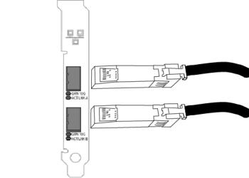
Connect the Direct Attach Cable
Insert theDirect Attachnetwork cableas shownbelow.
Typeof cabling:
•40Gigabit Ethernet overSFP+ Direct AttachedCable(Twinaxial) • Lengthis 7meters max.
•25Gigabit Ethernet overSFP28Direct AttachedCable(Twinaxial) • Lengthis 5meters max.
• Foroptimal performance, must useCA-25G-LwithRS-FEC and25GBASE-CR
•10Gigabit Ethernet overSFP+ Direct AttachedCable(Twinaxial)
• Lengthis 10meters max.
PCI Hot Plug Support
Most Intel® Ethernet ServerAdapters areenabledforuseinselectedservers equippedwithHot Plugsupport. Exceptions: Intel Gigabit QuadPort Serveradapters donot support Hot Plugoperations.
If youreplaceanadapterinaHot Plugslot, donot placetheremovedadapterback intothesamenetwork until theserverhas rebooted(unless youreturnit tothesameslot andsameteam as before). This prevents a conflict inhavingtwoof thesameEthernet addresses onthesamenetwork.
Thesystem will requireareboot if you

•Changetheprimary adapterdesignator.
•Addanew adaptertoanexistingteam andmakethenew adaptertheprimary adapter.
•Removetheprimary adapterfrom thesystem andreplaceit withadifferent typeof adapter.
NOTE: ToreplaceanexistingSLA-teamedadapterinaHot Plugslot, first unplugtheadapter cable. Whentheadapteris replaced, reconnect thecable.
PCI Hot Plug Support for Microsoft* Windows* Operating Systems
Intel® network adapters areenabledforuseinselectedservers equippedwithPCI Hot Plugsupport and running Microsoft* Windows* operatingsystems. FormoreinformationonsettingupandusingPCI Hot Plug support inyourserver, seeyourhardwareand/orHot Plugsupport documentationfordetails. PCI Hot Plug only works whenyouhot pluganidentical Intel network adapter.
NOTES:
•TheMAC address anddriverfrom theremovedadapterwill beusedby thereplacement adapterunless youremovetheadapterfrom theteam andaddit back in. If youdonot removeandrestorethereplacement adapterfrom theteam, andtheoriginal adapteris used elsewhereonyournetwork, aMAC address conflict will occur.
•ForSLA teams, ensurethat thereplacement NIC is amemberof theteam beforeconnecting it totheswitch.

Microsoft* Windows* Installation and Configuration
Installing Windows Drivers and Software
NOTE: Tosuccessfully install oruninstall thedrivers orsoftware, youmust haveadministrative privileges onthecomputercompletinginstallation.
Install the Drivers
NOTES:
•This will updatethedrivers forall supportedIntel® network adapters inyoursystem.
•TheRoll Back Driverfeatureof Windows Server(availableontheAdapterProperties dialog's Driver tab)will not work correctly if anadapterteam orIntel PROSet arepresent onthesystem. BeforeyouusetheRoll Back Driverfeature, useIntel PROSet toremoveany teams, thenremoveIntel PROSet using Programs and Features from theControl Panel of Windows.
•UsingMicrosoft Windows UpdatetoupgradeordowngradeyourEthernet network drivers is not supported. Pleasedownloadthelatest driverpackagefrom the support website.
Beforeinstallingorupdatingthedrivers, insert youradapter(s)inthecomputerandpluginthenetwork cable. WhenWindows discovers thenew adapter, it attempts tofindanacceptableWindows driveralready installed withtheoperatingsystem.
If found, thedriveris installedwithout any userintervention. If Windows cannot findthedriver, theFoundNew HardwareWizardwindow is displayed.
Regardless of whetherWindows finds thedriver, it is recommendedthat youfollow theprocedurebelow to install thedriver. Drivers forall Intel adapters supportedby this softwarereleaseareinstalled.
1.Downloadthelatest drivers from the support website andtransferthem tothesystem.
2.If theFoundNew HardwareWizardscreenis displayed, click Cancel.
3.Start theautorunlocatedinthedownloadedthesoftwarepackage. Theautorunmay automatically start afteryouhaveextractedthefiles.
4.Click Install Drivers and Software.
5.Follow theinstructions intheinstall wizard.
NOTE: Intel® PROSet is installedby default whenyouinstall thedevicedrivers.
Installing the Base Driver and Intel® PROSet on Nano Server
Driver Installation
NOTE: Installingdrivers requires administratorrights totheoperatingsystem.
Toinstall drivers onMicrosoft* Windows Server* NanoServer:

1.Identify whichdrivers toinject intotheoperatingsystem.
2.Createadirectory from whichtoinstall thedrivers. Forexample, C:\Nano\Drivers
3.Copy theappropriatedrivers fortheoperatingsystem andhardware. Forexample, "copy D:\PROXGB\Winx64\NDIS65\*.* c:\Nano\Drivers /y"
4.If youareusingtheNew-NanoServerImagemodule, usetheabovepathforthe -DriversPathpara- meter. Forexample, "New-NanoServerImage ...-DriversPathC:\Nano\Drivers"
5.If youareusingDISM.exeas well, usetheabovepathforthe/AddDriverparameter. Forexample, "DISM .../Add-DriverC:\Nano\Drivers"
Intel PROSet Installation
Toinstall Intel PROSet onMicrosoft* Windows Server* NanoServer:
1.UsetheNew-NanoServerImagecmdlet toaddthePROSetNS.zipfilefrom the
.\Disk\APPS\PROSETDX\NanoServerdirectory toyour -CopyPathparameter.
2.AppendtheNanoSetup.ps1file(locatedinthesamedirectory)toyour -SetupCompleteCommands parameter.
Forexample:
New-NanoServerImage ...
-CopyPath "<PATH>\PROSetNS.zip", "<PATH>\NanoSetup.ps1" `
-SetupCompleteCommands "PowerShell ""C:\NanoSetup.ps1"""
Seethelink below formoreinformationondeployingaNanoServerimageandusingthecmdlet: https://msdn.microsoft.com/en-us/library/mt126167.aspx
Installing Intel PROSet
Intel PROSet forWindows DeviceManageris anadvancedconfigurationutility that incorporates additional configurationanddiagnostic features intothedevicemanager.
NOTES:
•Youmust install Intel® PROSet forWindows DeviceManagerif youwant touseIntel® ANS teams orVLANs.
•Intel PROSet forWindows DeviceManageris installedby default whenyouinstall the devicedrivers. Forinformationonusage, see UsingIntel® PROSet forWindows Device Manager.
Intel PROSet forWindows DeviceManageris installedwiththesameprocess usedtoinstall drivers.
NOTES:
•Youmust haveadministratorrights toinstall oruseIntel PROSet forWindows Device Manager.
•UpgradingPROSet forWindows DeviceManagermay takeafew minutes.

1. Ontheautorun, click Install Base Drivers and Software.
NOTE: Youcanalsorunsetup64.exefrom thefiles downloadedfrom CustomerSupport.
2.Proceedwiththeinstallationwizarduntil the Custom Setup pageappears.
3.Select thefeatures toinstall.
4.Follow theinstructions tocompletetheinstallation.
If Intel PROSet forWindows DeviceManagerwas installedwithout ANS support, youcaninstall support by clicking Install Base Drivers and Software ontheautorun, orrunningsetup64.exe, andthenselectingthe Modify optionwhenprompted. From theIntel® Network Connections window, select Advanced Network Services thenclick Next tocontinuewiththeinstallationwizard.
Command Line Installation for Base Drivers and Intel® PROSet
Driver Installation
Thedriverinstall utility DxSetup.exeallows unattendedinstallationof drivers from acommandline.
NOTES:
•Intel® 10GbE Network Adapters donot support unattendeddriverinstallation.
•Intel PROSet cannot beinstalledwithmsiexec.exe. Youmust use DxSetup.exe.
Theseutilities canbeusedtoinstall thebasedriver, intermediatedriver, andall management applications for supporteddevices.
DxSetup.exe Command Line Options
By settingtheparameters inthecommandline, youcanenableanddisablemanagement applications. If parameters arenot specified, only existingcomponents areupdated.
DxSetup.exesupports thefollowingcommandlineparameters:
|
Parameter |
|
Definition |
|
|
|
|
||
|
|
|
|
|
|
BD |
|
BaseDriver |
|
|
|
|
"0", donot install thebasedriver. |
|
|
|
|
"1", install thebasedriver. |
|
|
|
|
|
|
|
ANS |
|
AdvancedNetwork Services |
|
|
|
|
"0", donot install ANS. If ANS is already installed, it will beuninstalled. |
|
|
|
|
"1", install ANS. TheANS property requires DMIX=1. |
|
|
|
|
NOTE: If theANS parameteris set toANS=1, bothIntel PROSet andANS |
|
|
|
|
will beinstalled. |
|
|
|
|
|
|
|
DMIX |
|
PROSet forWindows DeviceManager |
|
|
|
|
|
|
|
|
|
|
|
NOTE: If DMIX=0, ANS will not beinstalled. If DMIX=0andIntel PROSet, ANS, andFCoE arealready installed, Intel PROSet, ANS, andFCoE will be uninstalled.

Parameter |
Definition |
|
|
|
"1", install Intel PROSet feature. TheDMIX property requires BD=1. |
|
NOTE: If DMIX=0, ANS will not beinstalled. If DMIX=0andIntel PROSet, |
|
ANS, andFCoE arealready installed, Intel PROSet, ANS, andFCoE will be |
|
uninstalled. |
|
|
FCOE |
FibreChannel overEthernet |
|
"0", donot install FCoE. If FCoE is already installed, it will beuninstalled. |
|
"1", install FCoE. TheFCoE property requires DMIX=1. |
|
NOTE: Evenif FCOE=1is passed, FCoE will not beinstalledif theoperating |
|
system andinstalledadapters donot support FCoE. |
|
|
ISCSI |
iSCSI |
|
"0", donot install iSCSI. If iSCSI is already installed, it will beuninstalled. |
|
"1", install FCoE. TheiSCSI property requires DMIX=1. |
|
|
IWARP_ |
iWARP routing |
ROUTING |
"0", donot install iWARP routing. |
|
|
|
"1", install iWARP routing. |
|
|
IWARP_ |
Installs theiWARP firewall rule. Formoreinformationsee iWARP (Internet WideArea |
FIREWALL |
RDMA Protocol) section. |
|
"0", donot install iWARP firewall rule. |
|
"1", install iWARP firewall rule. If "1" is selected, thefollowingparameters areallowed |
|
inadditiontoIWARP_FIREWALL. |
•IWARP_FIREWALL_DOMAIN [0|1] - Applies firewall ruletocorporatedomains.
•IWARP_FIREWALL_PUBLIC [0|1] - Applies firewall ruletopublic networks
•IWARP_FIREWALL_PRIVATE [0|1] - Applies firewall ruletoprivatenetworks
FORCE |
"0", check that theinstalleddevicesupports afeature(FCOE, iSCSI)andonly install |
|
|
|
thefeatureif suchadeviceis found. |
|
|
|
"1", install thespecifiedfeatures regardless of thepresenceof supportingdevices. |
|
|
|
|
|
|
/q[r|n] |
/q --- |
silent install options |
|
|
r |
ReducedGUI Install (only displays critical warningmessages) |
|
n Silent install
Loading...