


Intel® Server Board
M10JNP2SB
User Guide
An overview of product features, functions, architecture, support specifications, and instructions
for essential component installation.
Rev 1.1
November 2019
M10JNP2SB
Intel® Server Products and Solutions
<Blank page>
|
|
|
Intel® Server Board M10JNP2SB User Guide |
|
|
|
|
|
|
|
Document Revision History |
|
|
|
|
|
Date |
Revision |
Changes |
|
October 2019 |
1.0 |
First release. |
|
|
|
|
|
October 2019 |
1.01 |
Added product regulatory compliance table. |
|
|
|
|
|
November 2019 |
1.1 |
Chapter 3 - Added Supported processors |
|
|
|
|
3

Intel® Server Board M10JNP2SB User Guide
Disclaimers
Intel technologies’ features and benefits depend on system configuration and may require enabled hardware, software, or service activation. Learn more at Intel.com, or from the OEM or retailer.
You may not use or facilitate the use of this document in connection with any infringement or other legal analysis concerning Intel products described herein. You agree to grant Intel a non-exclusive, royalty-free license to any patent claim thereafter drafted which includes subject matter disclosed herein.
No license (express or implied, by estoppel or otherwise) to any intellectual property rights is granted by this document.
The products described may contain design defects or errors known as errata which may cause the product to deviate from published specifications. Current characterized errata are available on request.
Intel disclaims all express and implied warranties, including without limitation, the implied warranties of merchantability, fitness for a particular purpose, and non-infringement, as well as any warranty arising from course of performance, course of dealing, or usage in trade.
Intel warranties that this product will perform to its published specifications. However, all computer systems are inherently subject to unpredictable system behavior under various environmental and other conditions.
This product is not intended to be the sole source for any critical data and the user must maintain a verified backup. Failure to do so or to comply with other user notices in the product user guide and specification documents may result in loss of or access to data.
Copies of documents which have an order number and are referenced in this document may be obtained by calling 1-800-548-4725 or by visiting www.intel.com/design/literature.htm.
Intel and the Intel logo, are trademarks of Intel Corporation or its subsidiaries in the U.S. and/or other countries. *Other names and brands may be claimed as the property of others.
Copyright © Intel Corporation. All rights reserved.
4
Intel® Server Board M10JNP2SB User Guide
Product Safety Overview
Heed safety instructions: Before working with your server product, whether you are using this guide or any other resource as a reference, pay close attention to the safety instructions. You must adhere to the assembly instructions in this guide to ensure and maintain compliance with existing product certifications and approvals. Use only the described, regulated components specified in this guide. Use of other products/components will void the UL listing and other regulatory approvals of the product and will most likely result in noncompliance with product regulations in the region(s) in which the product is sold.
Hazardous conditions, devices and cables: Hazardous electrical conditions may be present on power, telephone, and communication cables. Turn off the system and disconnect all telecommunications systems, networks, and modems attached to it before performing any service. Otherwise, personal injury or equipment damage can result.
Installing or removing jumpers: A jumper is a small plastic encased conductor that slips over two jumper pins. Some jumpers have a small tab on top that you can grip with your fingertips or with a pair of fine needle nosed pliers. If your jumpers do not have such a tab, take care when using needle nosed pliers to remove or install a jumper; grip the narrow sides of the jumper with the pliers, never the wide sides. Gripping the wide sides can damage the contacts inside the jumper, causing intermittent problems with the function controlled by that jumper. Take care to grip with, but not squeeze, the pliers or other tool you use to remove a jumper, or you may bend or break the pins on the board.
Electrostatic Discharge (ESD)
Electrostatic discharge can cause damage to your computer or the components within it. ESD can occur without the user feeling a shock while working inside the system chassis or while improperly handling electronic devices like processors, memory or other storage devices, and add-in cards.
Intel recommends the following steps be taken when performing any procedures described within this document or while performing service to any computer system.
•Where available, all system integration and/or service should be performed at a properly equipped ESD workstation.
•Wear ESD protective gear like a grounded antistatic wrist strap, sole grounders, and/or conductive shoes.
•Wear an anti-static smock or gown to cover any clothing that may generate an electrostatic charge.
•Remove all jewelry.
•Disconnect all power cables and cords before opening the Server Chassis
•Power down the system and remove power feed from the Server Board before performing any integration or service
•Touch any unpainted metal surface of the chassis before performing any integration or service.
•Hold all circuit boards and other electronic components by their edges only.
•After removing electronic devices from the system or from their protective packaging, place them component side up on to a grounded anti-static surface or conductive foam pad. Do not place electronic devices on to the outside of any protective packaging.
5
Intel® Server Board M10JNP2SB User Guide
Table of Contents
1. |
Introduction............................................................................................................................................................... |
10 |
|
|
1.1 |
Intel Server Board Use Disclaimer .......................................................................................................................... |
10 |
2. |
Server Board Overview............................................................................................................................................ |
11 |
|
|
2.1 |
Server Board Features Overview ............................................................................................................................. |
11 |
|
2.2 |
Server Board Component / Feature Identification........................................................................................... |
13 |
|
2.3 |
Server Board Mechanical Drawings........................................................................................................................ |
14 |
|
2.4 |
Product Architecture Overview................................................................................................................................ |
18 |
3. |
Processor Support.................................................................................................................................................... |
19 |
|
|
3.1 |
Processor Features........................................................................................................................................................ |
20 |
|
3.1.1 |
Intel® Xeon® E-2100 processor family.......................................................... |
Error! Bookmark not defined. |
|
3.1.2 |
Intel® Xeon® E-2200 processor family.......................................................... |
Error! Bookmark not defined. |
4. |
Memory Support....................................................................................................................................................... |
21 |
|
|
4.1 |
Supported Memory ....................................................................................................................................................... |
21 |
|
4.2 |
General Memory Population Rules......................................................................................................................... |
22 |
|
4.3 |
Memory RAS Features.................................................................................................................................................. |
22 |
5. |
Server Board I/O....................................................................................................................................................... |
23 |
|
|
5.1 |
PCIe Add-In Card Support.......................................................................................................................................... |
23 |
|
5.1.1 |
PCIe* Enumeration and Allocation ......................................................................................................................... |
23 |
|
5.2 |
1U One-Slot PCIe Riser Card Option (iPC – JNP1URISER)............................................................................ |
24 |
|
5.3 |
Networking........................................................................................................................................................................ |
24 |
|
5.4 |
USB....................................................................................................................................................................................... |
25 |
|
5.4.1 |
External USB 3.1 Connectors.................................................................................................................................... |
25 |
|
5.4.2 |
Front Panel USB 3.1 Connector ............................................................................................................................... |
25 |
|
5.5 |
Onboard SATA Support .............................................................................................................................................. |
26 |
|
5.5.1 |
SATADOM support........................................................................................................................................................ |
26 |
6. |
Server Management................................................................................................................................................. |
27 |
|
|
6.1 |
Shared Management Interface ................................................................................................................................. |
27 |
|
6.2 |
Embedded Web Server................................................................................................................................................ |
27 |
7. On-Board Connector/Header Pin-Out Overview .............................................................................................. |
29 |
||
|
7.1 |
Power Connectors ......................................................................................................................................................... |
29 |
|
7.2 |
Onboard Storage Connectors................................................................................................................................... |
30 |
|
7.2.1 |
SATA 6 Gbps Connectors ........................................................................................................................................... |
30 |
|
7.2.2 |
SATADOM 6 Gbps Connectors................................................................................................................................. |
30 |
|
7.2.3 |
SATA SGPIO Connector............................................................................................................................................... |
30 |
|
7.3 |
Fan Connectors............................................................................................................................................................... |
31 |
|
7.3.1 |
System Fan Connectors............................................................................................................................................... |
31 |
|
7.3.2 |
Processor Fan Connectors ......................................................................................................................................... |
31 |
|
7.4 |
Front Panel Headers and Connectors ................................................................................................................... |
31 |
|
7.4.1 |
Front Panel Header ....................................................................................................................................................... |
31 |
|
7.4.2 |
Front Panel USB 3.1 Connector ............................................................................................................................... |
31 |
6 |
|
|
|
|
Intel® Server Board M10JNP2SB User Guide |
|
7.5 |
Dedicated LAN Activity LED Headers..................................................................................................................... |
32 |
7.6 |
Other Headers and Connectors ............................................................................................................................... |
32 |
7.6.1 |
Serial Port Connectors................................................................................................................................................. |
32 |
7.6.2 |
Power Supply Monitoring Interface (PSMI) Connector .................................................................................. |
33 |
7.6.3 |
IPMB Header..................................................................................................................................................................... |
33 |
7.6.4 |
Chassis Intrusion Header ............................................................................................................................................ |
33 |
7.6.5 |
ID LED Header.................................................................................................................................................................. |
33 |
8. Reset and Recovery Jumpers................................................................................................................................. |
34 |
|
8.1 |
Clear CMOS Jumper Block......................................................................................................................................... |
34 |
8.2 |
BIOS Recovery Jumper................................................................................................................................................ |
35 |
9. Server Board and Essential System Component Installation and Removal ............................................... |
36 |
|
9.1 |
Installing the Server Board......................................................................................................................................... |
37 |
9.2 |
Server Board Removal ................................................................................................................................................. |
37 |
9.3 |
Installing the Processor............................................................................................................................................... |
38 |
9.4 |
Processor Heat Sink Installation.............................................................................................................................. |
41 |
9.5 |
Heat Sink Removal......................................................................................................................................................... |
42 |
9.6 |
Removing the Processor ............................................................................................................................................. |
43 |
9.7 |
Memory (DIMM) Installation ...................................................................................................................................... |
43 |
9.8 |
Memory (DIMM) Removal............................................................................................................................................ |
43 |
9.9 |
Connecting SATA Drives ............................................................................................................................................. |
44 |
9.10 |
Removing SATA Drives ................................................................................................................................................ |
44 |
9.11 |
Connecting System Fans............................................................................................................................................. |
45 |
9.12 |
Disconnecting System Fans....................................................................................................................................... |
46 |
Appendix A. |
Usage Tips............................................................................................................................................... |
47 |
Appendix B. |
Getting Help............................................................................................................................................ |
48 |
Appendix C. POST Code Errors.................................................................................................................................. |
49 |
|
Appendix D. |
Additional References.......................................................................................................................... |
58 |
Appendix E. |
Safety Instructions ................................................................................................................................ |
59 |
Appendix F. Safety and Regulatory Certifications................................................................................................. |
69 |
|
Appendix G. Statement Of Volatility ........................................................................................................................ |
72 |
|
Glossary ............................................................................................................................................................................. |
|
74 |
List of Figures |
|
|
Figure 1. Intel® Server Board M10JNP2SB ..................................................................................................................................... |
11 |
|
Figure 2. Server board component / feature identification..................................................................................................... |
13 |
|
Figure 3. Server board mounting holes ........................................................................................................................................... |
14 |
|
Figure 4. Component height restrictions ........................................................................................................................................ |
15 |
|
Figure 5. Major components and connectors 1 of 2 .................................................................................................................. |
16 |
|
Figure 6. Major components and connectors 2 of 2 .................................................................................................................. |
17 |
|
Figure 7. Intel® Server Board M10JNP2SB block diagram....................................................................................................... |
18 |
|
7
Intel® Server Board M10JNP2SB User Guide |
|
Figure 8. Memory subsystem architecture ..................................................................................................................................... |
21 |
Figure 9. DIMM slot identification ...................................................................................................................................................... |
21 |
Figure 10. PCIe slot identification ...................................................................................................................................................... |
23 |
Figure 11. 1U one-slot PCIe* riser card option (iPC – JNP1Uriser) ...................................................................................... |
24 |
Figure 12. Rear networking ports....................................................................................................................................................... |
24 |
Figure 13. External USB 3.1 Gen2 ports .......................................................................................................................................... |
25 |
Figure 14. Front panel USB 3.0 connector ..................................................................................................................................... |
26 |
Figure 15. SATADOM connector pinout .......................................................................................................................................... |
26 |
Figure 16. BMC embedded web server user interface............................................................................................................... |
28 |
Figure 17. Board jumper identification ............................................................................................................................................ |
34 |
Figure 18. Server board mounting hole location......................................................................................................................... |
36 |
Figure 19. Removing the socket protection cap .......................................................................................................................... |
38 |
Figure 20. Opening the socket lever ................................................................................................................................................. |
38 |
Figure 21. Opening the processor load plate................................................................................................................................ |
39 |
Figure 22. Installing the processor .................................................................................................................................................... |
39 |
Figure 23. Closing the load plate........................................................................................................................................................ |
40 |
Figure 24. Closing the socket lever.................................................................................................................................................... |
40 |
Figure 25. Installing the heat sink ...................................................................................................................................................... |
41 |
Figure 26. Connecting the fan cable ................................................................................................................................................. |
41 |
Figure 27. Removing the fan cable .................................................................................................................................................... |
42 |
Figure 28. Removing the heat sink..................................................................................................................................................... |
42 |
Figure 29. DIMM installation................................................................................................................................................................. |
43 |
Figure 30. DIMM removal....................................................................................................................................................................... |
43 |
Figure 31. Attaching SATA cables ...................................................................................................................................................... |
44 |
Figure 32. Removing SATA cables ..................................................................................................................................................... |
44 |
Figure 33. System fan connector identification ........................................................................................................................... |
45 |
Figure 34. Connecting system fan cables ....................................................................................................................................... |
45 |
Figure 35. Removing system fan cables .......................................................................................................................................... |
46 |
List of Tables
Table 1. Intel® Server Board M10JNP2SB features/specifications ...................................................................................... |
11 |
|
Table 2. Intel® Xeon® E-2200 processor family features list................................................................................................... |
19 |
|
Table 3. |
Intel® Xeon® E-2100 processor family features list................................................................................................... |
19 |
Table 4. DIMM population recommendations .............................................................................................................................. |
22 |
|
Table 5. Memory RAS features............................................................................................................................................................ |
22 |
|
Table 6. |
One-slot PCIe* riser card slot description..................................................................................................................... |
24 |
Table 7. |
10/100/1000 Mbps LAN link/activity LED matrix...................................................................................................... |
25 |
Table 8 PWR1 pin-out............................................................................................................................................................................. |
29 |
|
Table 9. PWR2 pin-out............................................................................................................................................................................ |
29 |
|
Table 10. SATA connector pin-out.................................................................................................................................................... |
30 |
|
8 |
|
|
Intel® Server Board M10JNP2SB User Guide |
|
Table 11. SATADOM connector pin-out.......................................................................................................................................... |
30 |
Table 12. SGPIO connector pin-out.................................................................................................................................................. |
30 |
Table 13. System fan connector pin-out......................................................................................................................................... |
31 |
Table 14. Processor fan connector pin-out ................................................................................................................................... |
31 |
Table 15. Front panel header pin-out.............................................................................................................................................. |
31 |
Table 16. Front panel USB 3.1 connector pinout........................................................................................................................ |
31 |
Table 17. LAN 3 activity LED header................................................................................................................................................. |
32 |
Table 18. LAN 4 activity LED header................................................................................................................................................. |
32 |
Table 19. TPM header pin-out............................................................................................................................................................. |
32 |
Table 20. COM1 port pin-out............................................................................................................................................................... |
32 |
Table 21. COM2 port pin-out............................................................................................................................................................... |
33 |
Table 22. PSMI connector pin-out..................................................................................................................................................... |
33 |
Table 23. IPMB header pin-out ........................................................................................................................................................... |
33 |
Table 24. Chassis intrusion header pin-out................................................................................................................................... |
33 |
Table 25. ID LED header pin-out ........................................................................................................................................................ |
33 |
Table 26. PEI phase.................................................................................................................................................................................. |
50 |
Table 27. Product safety compliance ............................................................................................................................................... |
69 |
Table 28. Product EMC compliance .................................................................................................................................................. |
69 |
Table 29. Product regulatory compliance markings .................................................................................................................. |
70 |
Table 30. Product regulatory compliance ...................................................................................................................................... |
71 |
Table 31. Server board components ................................................................................................................................................ |
73 |
9

Intel® Server Board M10JNP2SB User Guide
1.Introduction
This user guide provides a high level overview of the features, functions, and architecture of the Intel® Server Board M10JNP2SB. This document replaces the document previously known as the Technical Product Specification (TPS).
This guide is divided in two main parts going from chapters 2 to 8 providing information about the server board features and functions, followed by instructions on how to install or service essential system components on chapter 9.
For additional information about this server board, refer to the documents listed in Appendix D.
1.1Intel Server Board Use Disclaimer
Intel Corporation server boards support add-in peripherals and contain a number of high-density VLSI and power delivery components that need adequate airflow to cool. It is the responsibility of the system integrator to consult vendor datasheets and operating parameters to determine the amount of airflow required for a specific system configuration and operating environment. Intel Corporation cannot be held responsible if components fail or the server board does not operate correctly when used outside any of its published operating or non-operating limits.
10
Intel® Server Board M10JNP2SB User Guide
2.Server Board Overview
The Intel® Server Board M10JNP2SB is a monolithic printed circuit board assembly with features for data center and office environments running multiple applications under a continuous work load. This server board is designed to support the Intel® Xeon® E 2200 processor family.
Figure 1. Intel® Server Board M10JNP2SB
2.1Server Board Features Overview
Table 1. Intel® Server Board M10JNP2SB features/specifications
Feature |
|
|
Description |
Processor support |
|
• One LGA1151 processor socket |
|
|
|||
|
|
• Supports one of the following processors: |
|
|
|
|
o Intel® Xeon E-2224 processor |
|
|
|
o Intel® Xeon E-2236 processor |
|
|
|
o Intel® Xeon E-2278G processor |
|
|
• Maximum supported Thermal Design Power (TDP) of up to 95 W |
|
|
|
Note: Server Systems based on this server board may support a lower maximum Thermal |
|
|
|
Design Power (TDP). Consult chassis vendor specifications for maximum supported processor |
|
|
|
TDP limits. |
|
|
|
|
|
Memory |
|
• |
Four DIMM Slots |
|
|
• |
Two memory channels |
|
|
• DDR4 UDIMM ECC, 2666 MT/s, 1.2V |
|
|
|
• Up to 128GB total installed memory |
|
|
|
|
|
Chipset |
|
Intel® C246 Chipset |
|
|
|
|
|
Network Ports |
|
• Four 1GbE Base-T, RJ45 |
|
|
|
• One dedicated management port, RJ45 |
|
|
|
|
|
Onboard Storage Support |
|
• Six SATA 6 Gbps ports (6 Gb/s, 3 Gb/s and 1.5 Gb/s transfer rates are supported) |
|
|
|
• Two 7-pin SATA-DOM connectors |
|
11

|
|
Intel® Server Board M10JNP2SB User Guide |
|
|
|
Feature |
|
Description |
|
Embedded SATA software RAID |
|
|
• |
Intel® RSTe |
|
|
|
PCIe* Add-in Card Slots |
• |
Slot 1: PCIe* 3.0 x8 slot (x4 electrical) |
|
• Slot 2: PCIe* 3.0 x8 slot (x8 electrical) |
|
|
• Slot 3: PCIe* 3.0 x16 slot (x8 electrical) |
|
|
|
|
Riser Card Support |
: Support for one PCIe 3.0 riser card on PCIe slot 3. (Sold separately. Optional Intel Accessory) |
|
|
||
|
|
|
Video |
• |
Integrated 2D video controller |
|
• 16 MB of DDR4 video memory |
|
|
• One DB-15 external connector |
|
|
• Two External Display Port connectors |
|
|
|
|
USB |
• |
Four external USB 3.1 Gen2 ports |
|
• One 2x10 pin connector providing front panel support for (2) USB 3.1 Gen1 ports |
|
|
|
|
Serial Port |
• Two internal DH-10 serial port connectors |
|
|
||
|
|
|
Server Management |
• |
Integrated baseboard management controller, IPMI 2.0 compliant |
|
• Dedicated RJ45 management port |
|
|
• |
Shared management interface |
|
|
|
Security |
• |
Trusted platform module 2.0 support (China Version) – iPC JNPTPMCH |
|
|
(accessory option) |
|
• Trusted platform module 2.0 support (Rest of World) – iPC JNPTPM |
|
|
|
(accessory option) |
|
|
|
System Fan Support |
• |
Two 4-pin processor fan headers |
|
• Six 6-pin front system fan headers |
|
|
• One 4-pin rear system fan header |
|
|
|
|
Front Panel Support |
• One 2x12 pin SSI front panel header |
|
|
||
|
|
|
12

Intel® Server Board M10JNP2SB User Guide
2.2Server Board Component / Feature Identification
Figure 2. Server board component / feature identification
13
Intel® Server Board M10JNP2SB User Guide
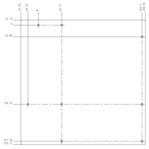
2.3Server Board Mechanical Drawings
Figure 3. Server board mounting holes
14
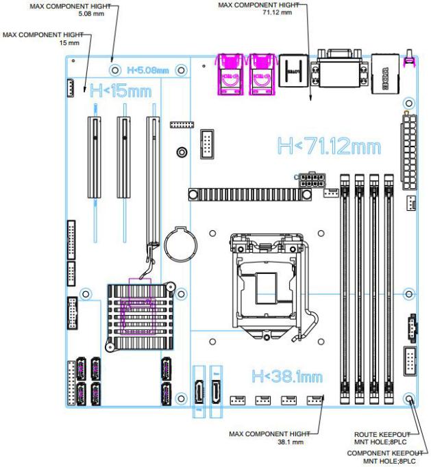
Intel® Server Board M10JNP2SB User Guide
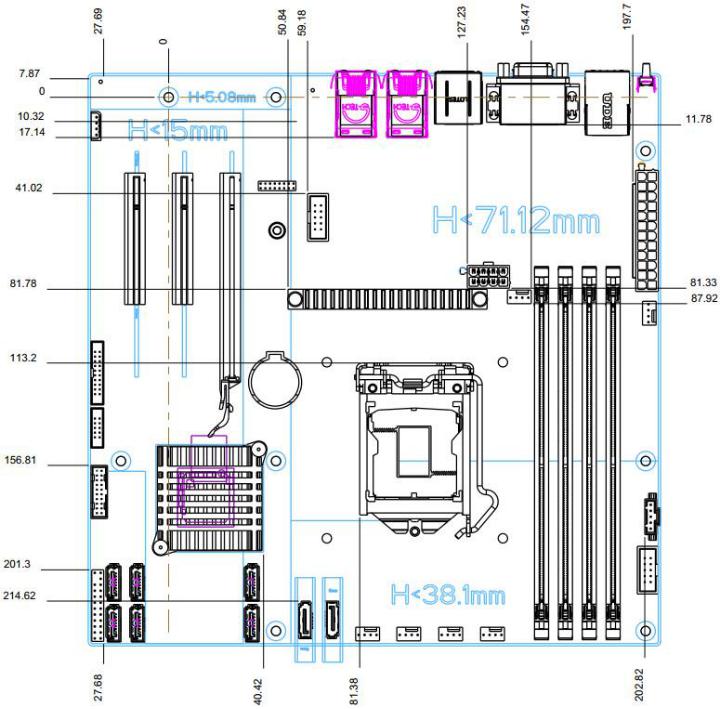
Figure 4. Component height restrictions
15
Intel® Server Board M10JNP2SB User Guide
Figure 5. Major components and connectors 1 of 2
16
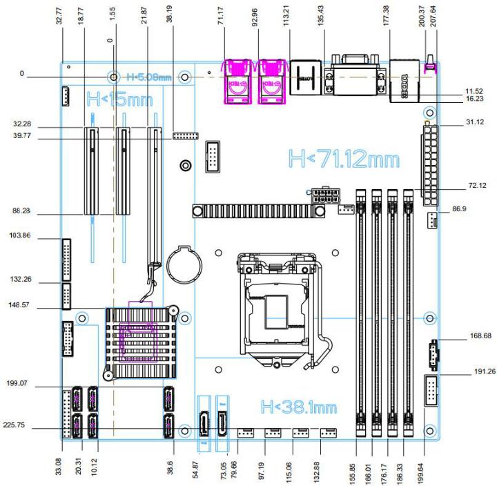
Intel® Server Board M10JNP2SB User Guide
Figure 6. Major components and connectors 2 of 2
17
Intel® Server Board M10JNP2SB User Guide
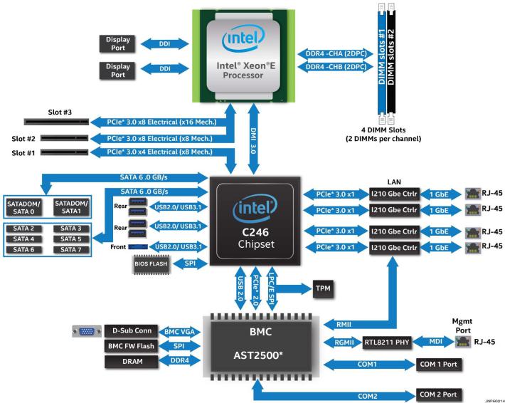
2.4Product Architecture Overview
The architecture of Intel® Server Board M10JNP2SB is developed around the integrated features and functions of the Intel® Xeon® E-2200 processor family, the Intel® C246 chipset (PCH), Intel® Ethernet Controller I210, and the ASPEED* AST2500 baseboard management controller (BMC).
Figure 7 provides an overview of the server board architecture, showing the features and interconnects of each of the major sub-system components.
Figure 7. Intel® Server Board M10JNP2SB block diagram
18

Intel® Server Board M10JNP2SB User Guide
3.Processor Support
The server board includes one LGA1151 processor socket compatible with select models from the Intel® Xeon® E-2100 and Intel® Xeon® E-2200 processor families with a maximum Thermal Design Power (TDP) of 95 W.
The Intel Server Board M10JNP2SB has been validated to support the following Intel processors:
•Intel® Xeon E-2104G Processor
•Intel® Xeon E-2124 Processor
•Intel® Xeon E-2124G Processor
•Intel® Xeon E-2126G Processor
•Intel® Xeon E-2134 Processor
•Intel® Xeon E-2136 Processor
•Intel® Xeon E-2146G Processor
•Intel® Xeon E-2174G Processor
•Intel® Xeon E-2176G Processor
•Intel® Xeon E-2186G Processor
•Intel® Xeon E-2224 Processor
•Intel® Xeon E-2236 Processor
•Intel® Xeon E-2278G Processor
Table 3 and Table 2 provide a comparison of specifications between the supported processors.
Table 2. Intel® Xeon® E-2100 processor family features list
|
|
Base |
Max Intel® |
Intel® UHD |
Intel® |
|
|
|
Turbo Boost |
Smart |
|||
SKU |
Cores/threads |
Speed |
Graphics |
|||
Technology 2.0 |
Cache |
|||||
|
|
(GHz) |
P630 |
|||
|
|
Speed (GHz) |
(MB) |
|||
|
|
|
|
|||
E-2186G |
6/12 |
3.8 |
4.7 |
Yes |
12 |
|
|
|
|
|
|
|
|
E-2176G |
6/12 |
3.7 |
4.7 |
Yes |
12 |
|
|
|
|
|
|
|
|
E-2174G |
4/8 |
3.8 |
4.7 |
Yes |
8 |
|
|
|
|
|
|
|
|
E-2146G |
6/12 |
3.5 |
4.5 |
Yes |
12 |
|
|
|
|
|
|
|
|
E-2144G |
4/8 |
3.6 |
4.5 |
Yes |
8 |
|
|
|
|
|
|
|
|
E-2136 |
6/12 |
3.3 |
4.5 |
No |
12 |
|
|
|
|
|
|
|
|
E-2134 |
4/8 |
3.5 |
4.5 |
No |
8 |
|
|
|
|
|
|
|
|
E-2126G |
6/12 |
3.3 |
4.5 |
Yes |
12 |
|
|
|
|
|
|
|
|
E-2124G |
4/8 |
3.4 |
4.5 |
Yes |
8 |
|
|
|
|
|
|
|
|
E-2124 |
4/8 |
3.3 |
4.3 |
No |
8 |
|
|
|
|
|
|
|
|
E-2104G |
4 |
3.2 |
N/A |
Yes |
8 |
|
|
|
|
|
|
|
Table 3. Intel® Xeon® E-2200 processor family features list
Features |
Intel® Xeon® E-2224 |
Intel® Xeon® E-2236 |
Intel® Xeon® E-2278G |
|
Processor |
Processor |
Processor |
||
|
||||
Cores/Threads |
4/4 |
6/12 |
8/16 |
|
|
|
|
|
|
Max Turbo Frequency |
4.7 Ghz |
4.8 Ghz |
5.0 Ghz |
|
|
|
|
|
|
Base Frequency |
3.5 Ghz |
3.4 Ghz |
3.8 Ghz |
|
|
|
|
|
|
Intel® Smart Cache |
8 Mb |
12 Mb |
12 Mb |
|
|
|
|
|
|
Intel® UHD Graphics |
P360 |
N/A |
P360 |
|
|
|
|
|
|
DDR4 ECC UDIMM |
128 Gb |
128 Gb |
128 Gb |
|
|
|
|
|
19

Intel® Server Board M10JNP2SB User Guide
3.1Processor Features
The Intel® Xeon® E-2100 and Intel® Xeon® E-2200 processor families combine several key system components into a single processor package, and include the following features:
•Intel® Virtualization Technology (Intel® VT-x)
•Intel® Active Management Technology 11.0 (Intel® AMT)
•Intel® Trusted Execution Technology (Intel® TXT)
•Intel® Streaming SIMD Extensions 4.2 (Intel® SSE4.2)
•Intel® Hyperthreading Technology (Intel® HT Technology)
•Intel® 64 Architecture
•Execute Disable Bit
•Intel® Turbo Boost Technology 2.0
•Intel® Advanced Vector Extensions 2 (Intel® AVX2
•Intel® Advanced Encryption Standards New Instructions (Intel® AES-NI)
•PCLMULQDQ (Perform Carry Less Multiplication Quad word) instruction
•Intel® Secure Key
•Intel® Transactional Synchronization Extensions (Intel® TSX-NI)
•PAIR – Power Aware Interrupt Routing
•SMEP – Supervisor Mode Execution Protection
•Intel® Boot Guard
•Intel® Software Guard Extensions (Intel® SGX)
•Intel Memory Protection Extensions (Intel® MPX)
•GMM Scoring Accelerator
•Intel® Processor Trace (Intel® PT)
•High Definition Content Protection (HDCP) 2.2
Note: Feature availability may vary between processor SKUs.
Refer to the Intel® Server Board M10JNP2SB Configuration Guide for a complete list of tested hardware.
20
Intel® Server Board M10JNP2SB User Guide
4.Memory Support
Figure 8. Memory subsystem architecture
The Intel® Xeon® E-2200 processor family includes an Integrated Memory Controller (IMC) capable of supporting two memory channels that can accommodate up to two DIMM slots per channel. On the Intel® Server Board M10JNP2SB, a total of four DIMM slots are provided as shown in Figure 9.
4.1Supported Memory
The server board supports the following:
•Only DDR4 DIMMs are supported
•Only Error Correction Code (ECC) enabled UDIMMs are supported
•Total installed system memory of up to 128GB
•DIMM speeds of 2666/2400 MT/s
•DIMMs organized as Single Rank (SR) or Dual Rank (DR)
The following illustration shows the location of the DIMM slots on the server board.
Figure 9. DIMM slot identification
21
Intel® Server Board M10JNP2SB User Guide
4.2General Memory Population Rules
The following memory population rules apply when installing DIMMs:
•When only one DIMM is used in the channels A or B, it must be populated in the black DIMM slot.
•Mixing DIMMs of a different type or rank organization is not supported
Table 4 lists the recommended DIMM populations for the server board.
Table 4. DIMM population recommendations
# of installed |
|
|
DIMM Slot |
|
|
|
|
|
|
|
|
DIMMs |
DIMM_A0 |
DIMM_A1 |
DIMM_B0 |
DIMM_B1 |
|
|
|
|
|
|
|
1 |
|
|
|
|
|
|
|
|
|
|
|
|
|
|
|
|
|
2 |
|
|
|
|
|
|
|
|
|
|
|
|
|
|
|
|
|
1 |
|
|
|
|
|
|
|
|
|
|
|
|
|
|
|
|
|
2 |
|
|
|
|
|
|
|
|
|
|
|
|
|
|
|
|
|
2 |
|
|
|
|
|
|
|
|
|
|
|
|
|
|
|
|
|
3 |
|
|
|
|
|
|
|
|
|
|
|
|
|
|
|
|
|
3 |
|
|
|
|
|
|
|
|
|
|
|
4 |
|
|
|
|
|
|
|
|
|
|
|
4.3Memory RAS Features
Each processor within the Intel® Xeon® E-2200 processor family has support for advanced memory RAS features as defined in Table 5.
|
Table 5. Memory RAS features |
|
|
|
|
RAS Feature |
Description |
|
|
x8 Single Device Data Correction (SDDC) via static virtual |
|
|
lockstep (Applicable to x8 DRAM DIMMs) |
|
|
Adaptive Data Correction (SR) (Applicable to x4 DRAM DIMMs) |
|
Device Data Correction |
x8 Single Device Data Correction + 1 bit (SDDC+1) (Applicable |
|
|
to x8 DRAM DIMMs) |
|
|
SDDDC + 1, and ADDDC (MR) + 1 (Applicable to x4 DRAM |
|
|
DIMMs) |
|
|
Full Memory Mirroring: An intra IMC method of keeping a |
|
|
duplicate (secondary or mirrored) copy of the contents of |
|
|
memory as a redundant backup for use if the primary memory |
|
|
fails. The mirrored copy of the memory is stored in memory of |
|
|
the same processor socket's IMC. Dynamic (without reboot) |
|
Memory Mirroring |
failover to the mirrored DIMMs is transparent to the OS and |
|
applications. |
||
|
||
|
Address Range/Partial Memory Mirroring: Provides further intra |
|
|
socket granularity to mirroring of memory by allowing the |
|
|
firmware or OS to determine a range of memory addresses to |
|
|
be mirrored, leaving the rest of the memory in the socket in |
|
|
non-mirror mode. |
22
Intel® Server Board M10JNP2SB User Guide
5.Server Board I/O
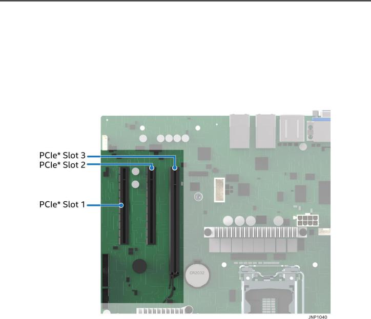
5.1PCIe Add-In Card Support
The server board provides three PCI Express* (PCIe*) slots labeled: “PCIe#1”, “PCIe#2”, and “PCIe#3”. The PCIe* interface of the Intel® Server Board M10JNP2SB is fully compliant with the PCIe* Base Specification, Revision 3.0 supporting the following PCIe* bit rates: 3.0 (8.0 GT/s), 2.0 (5.0 GT/s), and 1.0 (2.5 GT/s).
PCIe add-in card slots and their properties are as follows:
•Slot 1: PCIe* 3.0 x8 slot (x4 electrical)
•Slot 2: PCIe* 3.0 x8 slot (x8 electrical)
•Slot 3: PCIe* 3.0 x16 slot (x8 electrical)
Figure 10. PCIe slot identification
5.1.1PCIe* Enumeration and Allocation
The BIOS assigns PCI bus numbers in a depth-first hierarchy, in accordance with the PCI Local Bus Specification, Revision 3.0. The bus number is incremented when the BIOS encounters a PCI-PCI bridge device.
Scanning continues on the secondary side of the bridge until all subordinate buses are assigned numbers. PCI bus number assignments may vary from boot to boot with varying presence of PCI devices with PCI-PCI bridges.
If a bridge device with a single bus behind it is inserted into a PCI bus, all subsequent PCI bus numbers below the current bus are increased by one. The bus assignments occur once, early in the BIOS boot process, and never change during the pre-boot phase.
The BIOS resource manager assigns the PIC-mode interrupt for the devices that are accessed by the legacy code. The BIOS ensures that the PCI BAR registers and the command registers for all devices are correctly set
23
 Loading...