


MB820
Socket 478 Pentium® 4
Intel® 875P Chipset
Industrial Motherboard
USER’S MANUAL
Version 1.0

Acknowledgments
Award is a registered trademark of Award Software International, Inc.
PS/2 is a trademark of International Business Machines Corporation.
Intel and Pentium 4 are registered trademarks of Intel Corporation. Microsoft Windows is a registered trademark of Microsoft Corporation.
Winbond is a registered trademark of Winbond Electronics Corporation.
All other product names or trademarks are properties of their respective owners.
ii |
MB820 User’s Manual |

Table of Contents |
|
Introduction ....................................................... |
1 |
Checklist ........................................................................... |
1 |
Product Description .......................................................... |
2 |
Board Dimensions............................................................. |
3 |
Installations ....................................................... |
4 |
ATX Power Installation..................................................... |
5 |
Installing the Memory ....................................................... |
5 |
Setting the Jumpers ........................................................... |
6 |
Connectors on MB820..................................................... |
11 |
Watchdog Timer Configuration....................................... |
23 |
BIOS Setup....................................................... |
27 |
Drivers Installation ...................................... |
49 |
Intel 875P Chipset Software Intallation Utility ................. |
50 |
Realtek AC97 Codec Audio Driver Installation ............... |
53 |
Intel PRO LAN Drivers Installation................................. |
54 |
VGA Drivers Installation................................................. |
55 |
MB820 User’s Manual |
iii |

This page is intentionally left blank.
iv |
MB820 User’s Manual |

INTRODUCTION
Introduction
Checklist
Your MB820 Pentium® 4 motherboard package should include the items listed below:
∙The MB820 motherboard
∙This User’s Manual
∙1 Backplate
∙2 IDE Cable
∙1 Floppy Cable
∙2 SATA Cable
∙1 Dual-Serial-Port Cable
∙1 CD containing the following:
∙Chipset Drivers
∙Flash Memory Utility
MB820 User’s Manual |
1 |

INSTALLATIONS
Product Description
The MB820 Pentium® 4 motherboard incorporates the Intel 875P chipset that can utilize a single PGA478 processor of up to 3.2GHz or higher and supports FSB frequency of 400/533/800Mhz (100Mhz, 133Mhz, and 200Mhz HCLK respectively).
The 875P chipset is designed for use with the Pentium® 4 processor with 512-KB L2 cache on 0.13 micron process. The integrated MCH component provides the CPU interface, DDR interface, AGP interface, Hub Interface and AGP 8X graphics interface.
Four DDR memory sockets supports DDR 400/333/266 SDRAM DIMM modules of up to 4GB in capacity. ECC is also supported.
The board also comes optional with either integrated 10/100MB LAN support or an Intel® 82547GI Gigabit LAN controller. Two Serial ATA connectors offer 1.5 Gigabits/sec data throughput speed - faster than the most advanced parallel ATA.
Expansion is provided by four PCI slots, two ISA slots and one AGP8X interface. Other advanced features include six USB 2.0 ports, IrDA interface, PCI to ISA bridge, digital I/O, four serial ports, watchdog timer and audio function. Dimensions of the board are 12” by 9.5” in an ATX form factor.
2 |
MB820 User’s Manual |

INTRODUCTION
Board Dimensions
MB820 User’s Manual |
3 |

INSTALLATIONS
Installations
This section provides information on how to use the jumpers and connectors on the MB820 in order to set up a workable system. The topics covered are:
ATX Power Installation
Installing the Memory
Setting the Jumpers
Connectors on MB820
Watchdog Timer Configuration
4 |
MB820 User’s Manual |

INSTALLATIONS
ATX Power Installation
The system power is provided to the motherboard with the ATXP1 and ATXP2 ATX power connectors. ATXP2 is a 4-pin 12V power connector. ATXP1 is to be connected to a standard ATX power connector.
Installing the Memory
The MB820 motherboard supports four DDR memory sockets for a maximum total memory of 4GB in DDR memory type. You can install unbuffered & ECC DDR DIMMs. It supports DDR266 when installed with CPUs that have clock speeds of 400MHz. It supports DDR266/333 when installed with CPUs that have clock speeds of 533MHz. It supports DDR266/320/400 when installed with CPUs that have clock speeds of 800MHz. The board provides dual channel functionality for its DIMM slots. DIMM1/2is for one channel and DIMM3/4 is for another channel. Enabling dual channels can increase data access rates by putting two similar-size DDR modules into two same-color DIMM slots.
Basically, the system memory interface has the following features: Supports two 64-bit wide DDR data channels
Available bandwidth up to 3.2GB/s (DDR400) for single-channel mode and 6.4GB/s (DDR400) in dual-channel mode.
Supports ECC DIMMs.
Supports 128Mb, 256Mb, 512Mb, 1Gb DDR technologies. Supports only x8, x16, DDR devices with four banks Registered DIMMs not supported
Supports opportunistic refresh
Up to 16 simultaneously open pages (four per row, four rows maximum)
MB820 User’s Manual |
5 |

INSTALLATIONS
Setting the Jumpers
Jumpers are used on MB820 to select various settings and features according to your needs and applications. Contact your supplier if you have doubts about the best configuration for your needs. The following lists the connectors on MB820 and their respective functions.
Jumper Locations on MB820............................................................. |
7 |
JP1: RS232/422/485 (COM2) Selection .......................................... |
8 |
JP2: COM1 RS232 +5V/+12V Power Setting ................................. |
8 |
JP3: COM2 RS232 +5V/+12V Power Setting ................................. |
8 |
JP4: Clear CMOS Contents................................................................ |
9 |
JP5: COM3 RS232 +5V/+12V Power Setting ................................. |
9 |
JP6: COM4 RS232 +5V/+12V Power Setting ................................. |
9 |
JP7: DiskOnChip Address Select ..................................................... |
10 |
JP8: Onboard VGA Enable/Disable................................................. |
10 |
6 |
MB820 User’s Manual |
INSTALLATIONS
Jumper Locations on MB820
Jumper Locations on MB820 .............................................................. |
Page |
JP1: RS232/422/485 (COM2) Selection.................................................. |
8 |
JP2: COM1 RS232 +5V/+12V Power Setting ........................................ |
8 |
JP3: COM2 RS232 +5V/+12V Power Setting ........................................ |
8 |
JP4: Clear CMOS Contents ....................................................................... |
9 |
JP5: COM3 RS232 +5V/+12V Power Setting ........................................ |
9 |
JP6: COM4 RS232 +5V/+12V Power Setting ........................................ |
9 |
JP7: DiskOnChip Address Select............................................................. |
10 |
JP8: Onboard VGA Enable/Disable ........................................................ |
10 |
MB820 User’s Manual |
7 |
INSTALLATIONS
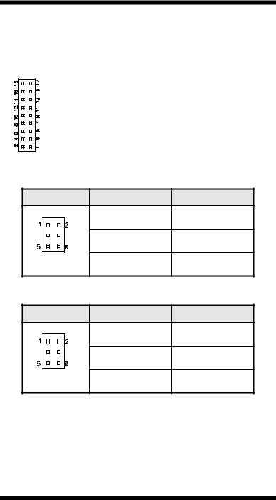
JP1: RS232/422/485 (COM2) Selection
COM1 is fixed for RS-232 use only.
J3, COM2 is selectable for RS232, RS-422 and RS-485.
The following table describes the jumper settings for COM2 selection.
COM2 |
RS-232 |
RS-422 |
RS-485 |
|
Function |
||||
|
|
|
||
|
Short: |
Short: |
Short: |
|
|
1-2 |
3-4 |
5-6 |
|
Jumper |
9-11 |
7-9 |
7-9 |
|
Setting |
10-12 |
8-10 |
8-10 |
|
(pin closed) |
15-17 |
13-15 |
13-15 |
|
|
16-18 |
14-16 |
14-16 |
JP2: COM1 RS232 +5V/+12V Power Setting |
|
|
JP2 |
Setting |
Function |
|
Pin 1-2 |
+12V |
|
Short/Closed |
|
|
Pin 3-4 |
Normal |
|
Short/Closed |
|
|
Pin 5-6 |
+5V |
|
Short/Closed |
|
JP3: COM2 RS232 +5V/+12V Power Setting |
|
|
JP3 |
Setting |
Function |
|
Pin 1-2 |
+12V |
|
Short/Closed |
|
|
Pin 3-4 |
Normal |
|
Short/Closed |
|
|
Pin 5-6 |
+5V |
|
Short/Closed |
8 |
MB820 User’s Manual |
INSTALLATIONS
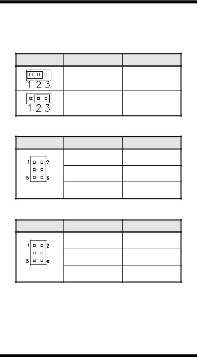
JP4: Clear CMOS Contents
Use JP4, a 3-pin header, to clear the CMOS contents. Note that the ATX-power connector should be disconnected from the motherboard before clearing CMOS.
JP4 |
Setting |
|
Function |
|
Pin 1-2 |
|
Normal |
|
Short/Closed |
|
|
|
|
|
|
|
Pin 2-3 |
Clear CMOS |
|
|
Short/Closed |
||
|
|
|
|
JP5: COM3 RS232 +5V/+12V Power Setting |
|
||
JP5 |
Setting |
|
Function |
|
Pin 1-2 |
|
+12V |
|
Short/Closed |
|
|
|
Pin 3-4 |
|
Normal |
|
Short/Closed |
|
|
|
Pin 5-6 |
|
+5V |
|
Short/Closed |
|
|
JP6: COM4 RS232 +5V/+12V Power Setting |
|
||
JP6 |
Setting |
Function |
|
Pin 1-2 |
+12V |
|
Short/Closed |
|
|
Pin 3-4 |
Normal |
|
Short/Closed |
|
|
Pin 5-6 |
+5V |
|
Short/Closed |
MB820 User’s Manual |
9 |

INSTALLATIONS
JP7: DiskOnChip Address Select
JP7 |
Address |
D0000-D7FFF
D8000-DFFFF (default)
JP8: Onboard VGA Enable/Disable
Use JP8 to enable or disable the onboard VGA controller.
JP8 |
Setting |
Onboard VGA |
|
Pin 1-2 |
Enabled |
|
Short/Closed |
|
|
|
|
|
Pin 2-3 |
Disabled |
|
Short/Closed |
|
|
|
10 |
MB820 User’s Manual |

INSTALLATIONS
Connectors on MB820
The connectors on MB820 allows you to connect external devices such as keyboard, floppy disk drives, hard disk drives, printers, etc. The following table lists the connectors on MB820 and their respective functions.
Connector Locations on MB820 .......................................... |
12 |
ATXP1: ATX Power Supply Connector............................... |
13 |
ATXP2: ATX 12V Power Connector................................... |
13 |
DIMM1, DIMM2: DDR Channel A Connectors.................. |
13 |
DIMM3, DIMM4: DDR Channel B Connectors.................. |
13 |
AGP1: AGP Slot.................................................................... |
13 |
PCI1, PCI2, PCI3, PCI4: PCI Slots...................................... |
13 |
SL1, SL2: ISA Slots............................................................... |
13 |
CN1: PS/2 Keyboard and PS/2 Mouse Connectors............. |
14 |
CN2: 4-port USB Connector ................................................ |
14 |
CN3, J3: Serial Ports............................................................. |
14 |
CN4: Parallel Port Connector............................................... |
15 |
CN6: VGA CRT Connector.................................................. |
15 |
CN7: USB and LAN RJ45 Connectors ................................ |
16 |
CN8: Audio Connector ......................................................... |
16 |
J1: IrDA Connector ............................................................... |
16 |
J4: CD-In Audio Connector.................................................. |
16 |
J5, J6: Serial ATA (SATA) Connectors................................ |
17 |
J8, J10: COM3 and COM4 Serial Ports Connector ............ |
17 |
J9: Wake On LAN Connector ............................................... |
17 |
J11: Digital I/O Connector (4 in, 4 out)............................... |
18 |
J12: System Function Connector.......................................... |
18 |
FAN1: CPU Fan Power Connector ...................................... |
20 |
FAN2: VGA Fan Power Connector ..................................... |
20 |
FAN3: Chassis Fan Power Connector.................................. |
20 |
FDD1: Floppy Drive Connector ........................................... |
21 |
IDE, IDE2: Primary and Secondary IDE Connectors .......... |
22 |
MB820 User’s Manual |
11 |

INSTALLATIONS
Connector Locations on MB820
12 |
MB820 User’s Manual |
INSTALLATIONS
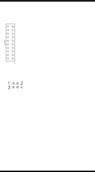
ATXP1: ATX Power Supply Connector
ATXP1 is a 20-pin ATX power supply connector. Refer to the following table for the pin out assignments.
11 |
1 |
|
|
|
Signal Name |
|
|
Pin # |
|
Pin # |
|
|
Signal Name |
|
|||||
|
|
|
|
|
|
|
|
3.3V |
11 |
|
1 |
|
|
|
3.3V |
|
|||
|
|
|
|
|
|
|
|
-12V |
12 |
|
2 |
|
|
|
3.3V |
|
|||
|
|
|
|
|
|
|
|
Ground |
13 |
|
3 |
|
|
|
Ground |
|
|||
|
|
|
|
|
|
|
|
PS-ON |
14 |
|
4 |
|
|
|
+5V |
|
|||
|
|
|
|
|
|
|
|
Ground |
15 |
|
5 |
|
|
|
Ground |
|
|||
|
|
|
|
|
|
|
|
Ground |
16 |
|
6 |
|
|
|
+5V |
|
|||
|
|
|
|
|
|
|
|
Ground |
17 |
|
7 |
|
|
|
Ground |
|
|||
|
|
|
|
|
|
|
|
-5V |
18 |
|
8 |
|
|
Power good |
|
||||
20 |
10 |
|
|
|
|
+5V |
19 |
|
9 |
|
|
|
5VSB |
|
|||||
|
|
|
|
+5V |
20 |
|
10 |
|
|
|
+12V |
|
|||||||
|
|
|
|
|
|
|
|
|
|
|
|
|
|||||||
ATXP2: ATX 12V Power Connector |
|
|
|
||||||||||||||||
|
|
|
|
|
|
|
|
|
|
|
|
|
|
|
|||||
|
|
|
|
|
|
|
|
|
Pin # |
|
Signal Name |
|
|
|
|||||
|
|
|
|
|
|
|
|
|
|
|
|
|
|||||||
|
|
|
|
|
|
|
|
|
1 |
|
|
|
Ground |
|
|
|
|||
|
|
|
|
|
|
|
|
|
2 |
|
|
|
Ground |
|
|
|
|||
|
|
|
|
|
|
|
|
|
|
|
|
|
|
|
|||||
|
|
|
|
|
|
|
|
3 |
|
|
|
+12V |
|
|
|
||||
|
|
|
|
|
|
|
|
4 |
|
|
|
+12V |
|
|
|
||||
DIMM1, DIMM2: DDR Channel A Connectors
DIMM1 and DIMM2 are the first DDR channel connectors that must be use together at one time in order for the system to function properly.
DIMM3, DIMM4: DDR Channel B Connectors
DIMM3 and DIMM4 are the second DDR channel connectors that must be use together at one time in order for the system to function properly.
AGP1: AGP Slot
PCI1, PCI2, PCI3, PCI4: PCI Slots
SL1, SL2: ISA Slots
MB820 User’s Manual |
13 |
INSTALLATIONS
CN1: PS/2 Keyboard and PS/2 Mouse Connectors
PS/2 Mouse
PS/2 Keyboard
|
Keyboard |
Mouse |
Signal Name |
Signal Name |
|
|
|
Keyboard data |
1 |
1 |
Mouse data |
N.C. |
2 |
2 |
N.C. |
GND |
3 |
3 |
GND |
5V |
4 |
4 |
5V |
Keyboard clock |
5 |
5 |
Mouse clock |
N.C. |
6 |
6 |
N.C. |
CN2: 4-port USB Connector
CN2 is a USB connector consisting of four ports stacked vertically.
|
|
|
|
|
|
Pin |
|
|
Signal Name |
|
|
|
|
|
|
|
|
|
|
|
|
|
|
|
|
|
|
1 |
|
|
Ground |
|
|
|
|
|
|
|
|
|
|
||
|
|
|
|
|
|
2 |
|
|
USB+ |
|
|
CN2 |
|
|
3 |
|
|
USB- |
|
||
|
|
4 |
|
|
Vcc |
|
||||
|
|
|
|
|
|
|
|
|
||
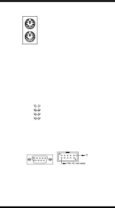
CN3, J3: Serial Ports
CN3 (COM1) is a DB-9 connector, while J3 is a COM2 pin-header connector. COM2 is optionally available as a DB-9 connector (CN5).
COM1 |
|
COM2 |
|
Signal Name |
Pin # |
Pin # |
Signal Name |
DCD, Data carrier detect |
1 |
6 |
DSR, Data set ready |
RXD, Receive data |
2 |
7 |
RTS, Request to send |
TXD, Transmit data |
3 |
8 |
CTS, Clear to send |
DTR, Data terminal ready |
4 |
9 |
RI, Ring indicator |
GND, ground |
5 |
10 |
Not Used |
14 |
MB820 User’s Manual |
 Loading...