


 Loading...
Intel® Desktop Board DX79SI
Product Guide
Order Number: G43991-001

Revision History
Revision |
Revision History |
Date |
-001 |
First release of the Intel® Desktop Board DX79SI Product Guide |
October 2011 |
Disclaimer
INFORMATION IN THIS DOCUMENT IS PROVIDED IN CONNECTION WITH INTEL® PRODUCTS. NO LICENSE, EXPRESS OR IMPLIED, BY ESTOPPEL OR OTHERWISE, TO ANY INTELLECTUAL PROPERTY RIGHTS IS GRANTED BY THIS DOCUMENT. EXCEPT AS PROVIDED IN INTEL’S TERMS AND CONDITIONS OF SALE FOR SUCH PRODUCTS, INTEL ASSUMES NO LIABILITY WHATSOEVER, AND INTEL DISCLAIMS ANY EXPRESS OR IMPLIED WARRANTY, RELATING TO SALE AND/OR USE OF INTEL PRODUCTS INCLUDING LIABILITY OR WARRANTIES RELATING TO FITNESS FOR A PARTICULAR PURPOSE, MERCHANTABILITY, OR INFRINGEMENT OF ANY PATENT, COPYRIGHT OR OTHER INTELLECTUAL PROPERTY RIGHT. Intel products are not intended for use in medical, life saving, or life sustaining applications. Intel may make changes to specifications and product descriptions at any time, without notice.
Intel Desktop Board DX79SI may contain design defects or errors known as errata which may cause the product to deviate from published specifications. Current characterized errata are available on request.
Contact your local Intel sales office or your distributor to obtain the latest specifications and before placing your product order.
Copies of documents which have an ordering number and are referenced in this document, or other Intel literature, may be obtained from Intel Corporation by going to the World Wide Web site at: http://www.intel.com/ or by calling 1-800-548-4725.
Intel, Intel Core, and Xeon are trademarks of Intel Corporation in the United States and/or other countries. * Other names and brands may be claimed as the property of others.
Copyright © 2011, Intel Corporation. All rights reserved.

Preface
This Product Guide gives information about board layout, component installation, BIOS update, and regulatory requirements for Intel® Desktop Board DX79SI.
Intended Audience
The Product Guide is intended for technically qualified personnel. It is not intended for general audiences.
Use Only for Intended Applications
All Intel Desktop Boards are evaluated as Information Technology Equipment (I.T.E.) for use in personal computers (PC) for installation in homes, offices, schools, computer rooms, and similar locations. The suitability of this product for other PC or embedded non-PC applications or other environments, such as medical, industrial, alarm systems, test equipment, etc. may not be supported without further evaluation by Intel.
Document Organization
The chapters in this Product Guide are arranged as follows:
1Desktop Board Features: a summary of product features
2Installing and Replacing Desktop Board Components: instructions on how to install the Desktop Board and other hardware components
3Updating the BIOS: instructions on how to update the BIOS
4Configuring for RAID: information about configuring your system for RAID
AError Messages and Indicators: information about BIOS error messages and beep codes
BRegulatory Compliance: describes the board’s adherence to safety standards and EMC regulations and its product certifications
Conventions
The following conventions are used in this manual:
 CAUTION
Cautions warn the user about how to prevent damage to hardware or loss of data.
 NOTE
NOTE
Notes call attention to important information.
iii
Intel Desktop Board DX79SI Product Guide
Terminology
The table below gives descriptions of some common terms used in the product guide.
Term |
Description |
|
|
GB |
Gigabyte (1,073,741,824 bytes) |
|
|
GHz |
Gigahertz (one billion hertz) |
|
|
KB |
Kilobyte (1024 bytes) |
|
|
MB |
Megabyte (1,048,576 bytes) |
|
|
Mb |
Megabit (1,048,576 bits) |
|
|
MHz |
Megahertz (one million hertz) |
|
|
iv

Contents
1 Desktop Board Features |
|
Supported Operating Systems.............................................................................. |
11 |
Desktop Board Components................................................................................. |
12 |
Processor.......................................................................................................... |
14 |
System Memory................................................................................................. |
15 |
Memory Configurations................................................................................ |
16 |
Intel® X79 Express Chipset.................................................................................. |
17 |
USB Support ..................................................................................................... |
17 |
USB 3.0 .................................................................................................... |
17 |
USB 2.0 .................................................................................................... |
17 |
Serial ATA......................................................................................................... |
17 |
Audio Subsystem ............................................................................................... |
18 |
LAN Subsystem ................................................................................................. |
18 |
Legacy I/O........................................................................................................ |
20 |
Expandability..................................................................................................... |
20 |
BIOS................................................................................................................ |
20 |
Serial ATA and IDE Auto Configuration........................................................... |
21 |
PCI and PCI Express* Auto Configuration ....................................................... |
21 |
Security Passwords..................................................................................... |
21 |
Back to BIOS Button ................................................................................... |
21 |
Hardware Management ....................................................................................... |
22 |
Hardware Monitoring and Fan Speed Control .................................................. |
22 |
Chassis Intrusion........................................................................................ |
22 |
Power Management ............................................................................................ |
23 |
Software Support ....................................................................................... |
23 |
ACPI.................................................................................................. |
23 |
Hardware Support ...................................................................................... |
23 |
Power Connectors ............................................................................... |
23 |
Fan Headers ....................................................................................... |
23 |
LAN Wake Capabilities.......................................................................... |
24 |
Instantly Available PC Technology.......................................................... |
24 |
+5 V Standby Power Indicator............................................................... |
24 |
Wake from USB .................................................................................. |
25 |
PME# Signal Wake-up Support.............................................................. |
26 |
WAKE# Signal Wake-up Support ........................................................... |
26 |
Wake from Consumer IR ...................................................................... |
26 |
Onboard System Control Switches ........................................................................ |
26 |
Power Switch ............................................................................................. |
27 |
Reset Switch.............................................................................................. |
27 |
System Initialization/Board Status LEDs ................................................................ |
27 |
System Initialization LEDs............................................................................ |
28 |
Status LEDs............................................................................................... |
29 |
Speaker............................................................................................................ |
29 |
Battery............................................................................................................. |
29 |
Real-Time Clock................................................................................................. |
29 |
v
Intel Desktop Board DX79SI Product Guide |
|
|
|
Bluetooth*/WiFi Module ...................................................................................... |
30 |
|
Bluetooth Technology.................................................................................. |
30 |
|
WiFi (802.11 Wireless) Technology................................................................ |
31 |
|
Remote Thermal Probe ....................................................................................... |
31 |
2 |
Installing and Replacing Desktop Board Components |
|
|
Before You Begin ............................................................................................... |
33 |
|
Installation Precautions....................................................................................... |
34 |
|
Prevent Power Supply Overload .................................................................... |
34 |
|
Observe Safety and Regulatory Requirements................................................. |
34 |
|
Installing the I/O Shield ...................................................................................... |
35 |
|
Installing the Desktop Board................................................................................ |
36 |
|
Installing a Processor ......................................................................................... |
37 |
|
Installing a Processor Fan Heat Sink.............................................................. |
41 |
|
Installing and Removing Memory.......................................................................... |
42 |
|
Installing DIMMs ........................................................................................ |
42 |
|
Removing DIMMs........................................................................................ |
44 |
|
Installing and Removing PCI Express x16 Add-in Cards ........................................... |
44 |
|
Installing PCI Express x16 Graphics Cards...................................................... |
44 |
|
Removing a PCI Express x16 Add-in Card....................................................... |
45 |
|
Installing Linked PCI Express x16 Graphics Cards............................................ |
46 |
|
Connecting SATA Cables ..................................................................................... |
48 |
|
Connecting to the Internal Headers and Connectors ................................................ |
49 |
|
Front Panel Audio Header ............................................................................ |
50 |
|
S/PDIF Header ........................................................................................... |
50 |
|
Chassis Intrusion Header ............................................................................. |
50 |
|
IEEE 1394a Header..................................................................................... |
51 |
|
USB 3.0 Connector ..................................................................................... |
51 |
|
Consumer IR (CIR) Headers ......................................................................... |
52 |
|
USB 2.0 Headers ........................................................................................ |
53 |
|
Front Panel Header ..................................................................................... |
53 |
|
Alternate Front Panel Power LED Header ........................................................ |
54 |
|
Connecting to the Audio System........................................................................... |
54 |
|
Connecting Chassis Fan and Power Supply Cables................................................... |
55 |
|
Connecting Chassis Fan Cables ..................................................................... |
55 |
|
Connecting Power Supply Cables .................................................................. |
56 |
|
Setting the BIOS Configuration Jumper ................................................................. |
57 |
|
Clearing Passwords ............................................................................................ |
58 |
|
Replacing the Battery ......................................................................................... |
59 |
|
Installing the WiFi/Bluetooth* Module in Your Chassis ............................................. |
64 |
|
Connecting the Remote Thermal Probe.................................................................. |
65 |
3 |
Updating the BIOS |
|
|
Updating the BIOS with the Intel® Express BIOS Update Utility................................. |
67 |
|
Updating the BIOS Using the F7 Function Key ........................................................ |
68 |
|
Updating the BIOS with the Intel® Flash Memory Update Utility ................................ |
68 |
|
Recovering the BIOS .......................................................................................... |
69 |
vi
Contents
4 Configuring for RAID Using Intel® Rapid Storage Technology |
|
Configuring the BIOS .................................................................................. |
71 |
Creating Your RAID Set ............................................................................... |
71 |
Loading the Intel RST RAID Drivers and Software (Required for |
|
Microsoft Windows XP Installation) .......................................................... |
72 |
Setting Up a “RAID Ready” System ............................................................... |
72 |
A Error Messages and Indicators |
|
BIOS Error Codes............................................................................................... |
73 |
BIOS Error Messages .......................................................................................... |
74 |
Port 80h POST Codes.......................................................................................... |
75 |
B Regulatory Compliance
Safety Standards ............................................................................................... |
79 |
Battery Caution .......................................................................................... |
79 |
European Union Declaration of Conformity Statement.............................................. |
80 |
Product Ecology Statements ................................................................................ |
81 |
Recycling Considerations ............................................................................. |
81 |
China RoHS ............................................................................................... |
84 |
EMC Regulations ................................................................................................ |
85 |
FCC Declaration of Conformity...................................................................... |
85 |
Canadian Department of Communications Compliance Statement...................... |
86 |
Japan VCCI Statement ................................................................................ |
86 |
Korea Class B Statement ............................................................................. |
87 |
Ensure Electromagnetic Compatibility (EMC) Compliance.................................. |
87 |
Product Certifications.......................................................................................... |
88 |
Board-Level Certifications ............................................................................ |
88 |
Chassisand Component-Level Certifications .................................................. |
89 |
ENERGY STAR*, e-Standby, and ErP Compliance .................................................... |
89 |
Figures
1. |
Intel Desktop Board DX79SI Components ........................................................ |
12 |
2. |
Memory Channel and DIMM Configuration ........................................................ |
16 |
3. |
LAN Connector LEDs ..................................................................................... |
19 |
4. |
Location of the Back to BIOS Button................................................................ |
22 |
5. |
Location of the Standby Power Indicator .......................................................... |
25 |
6. |
Onboard System Control Switches .................................................................. |
26 |
7. |
Location of the Diagnostic/Status LEDs ............................................................ |
27 |
8. |
Bluetooth/WiFi Module .................................................................................. |
30 |
9. |
Remote Thermal Probe .................................................................................. |
31 |
10. |
Installing the I/O Shield ................................................................................ |
35 |
11. |
Intel Desktop Board DX79SI Mounting Screw Hole Locations............................... |
36 |
12. |
Unlatch the Socket Levers ............................................................................. |
37 |
13. |
Open the Load Plate...................................................................................... |
38 |
14. |
Install the Processor ..................................................................................... |
39 |
15. |
Close the Load Plate ..................................................................................... |
40 |
16. |
Installing a Fan Heat Sink and Connecting the Cable to the Processor |
|
|
Fan Header.................................................................................................. |
41 |
17. |
Installing a DIMM ......................................................................................... |
43 |
18. |
Installing a PCI Express x16 Card ................................................................... |
45 |
vii
Intel Desktop Board DX79SI Product Guide |
|
|
19. |
Removing a PCI Express x16 Card .................................................................. |
46 |
20. |
Installing Linked PCI Express Graphics Cards.................................................... |
47 |
21. |
Connecting the Serial ATA Cables.................................................................... |
48 |
22. |
Internal Headers .......................................................................................... |
49 |
23. |
Back Panel Audio Connectors ......................................................................... |
54 |
24. |
Location of the Chassis Fan Headers................................................................ |
55 |
25. |
Connecting Power Supply Cables .................................................................... |
56 |
26. |
Location of the BIOS Configuration Jumper Block .............................................. |
57 |
27. |
Removing the Battery ................................................................................... |
63 |
28. |
Installing the WiFi/Bluetooth Module ............................................................... |
64 |
29. |
Connecting the Remote Thermal Probe ............................................................ |
65 |
30. |
POST Code LED Display ................................................................................. |
75 |
31. |
Intel Desktop Board DX79SI China RoHS Material Self Declaration Table .............. |
84 |
Tables |
|
|
1. |
Feature Summary.......................................................................................... |
9 |
2. |
Intel Desktop Board DX79SI Components ........................................................ |
13 |
3. |
LAN Connector LEDs ..................................................................................... |
20 |
4. |
System Initialization LEDs.............................................................................. |
28 |
5. |
Status LEDs................................................................................................. |
29 |
6. |
Front Panel Audio Header Signal Names........................................................... |
50 |
7. |
S/PDIF Header Signal Names ......................................................................... |
50 |
8. |
Chassis Intrusion Header Signal Names ........................................................... |
50 |
9. |
IEEE 1394a Header Signal Names ................................................................... |
51 |
10. |
USB 3.0 Connector ....................................................................................... |
51 |
11. |
Front Panel CIR Receiver (Input) Header Signal Names ...................................... |
52 |
12. |
Back Panel CIR Header Emitter (Output) Header Signal Names ........................... |
52 |
13. |
USB 2.0 Header Signal Names........................................................................ |
53 |
14. |
Front Panel Header Signal Names ................................................................... |
53 |
15. |
Alternate Front Panel Power LED Header Signal Names ...................................... |
54 |
16. |
Jumper Settings for the BIOS Setup Program Modes.......................................... |
58 |
17. |
BIOS Beep Codes ......................................................................................... |
73 |
18. |
Front-panel Power LED Blink Codes ................................................................. |
73 |
19. |
BIOS Error Messages .................................................................................... |
74 |
20. |
Port 80h POST Codes .................................................................................... |
76 |
21. |
Safety Standards.......................................................................................... |
79 |
22. |
EMC Regulations........................................................................................... |
85 |
23. |
Regulatory Compliance Marks......................................................................... |
88 |
viii

1 Desktop Board Features
This chapter briefly describes the features of Intel® Desktop Board DX79SI. Table 1 summarizes the major features of the Desktop Board.
Table 1. Feature Summary
Form Factor |
ATX (304.80 millimeters [12.00 inches] x 243.84 millimeters |
|
|
[9.60 inches]) |
|
|
|
|
Processor |
Support for Intel® Core™ i7 and Intel® Xeon® processors in the |
|
|
LGA2011 package with: |
|
|
• |
Two PCI Express 3.0 x16 graphics interfaces (x16 electrical) |
|
• |
One PCI Express 3.0 x16 (x8 electrical) |
|
• |
Quad-channel memory interface |
|
|
|
Main Memory |
Eight 240-pin DDR3 SDRAM Dual Inline Memory Module (DIMM) |
|
|
sockets arranged in four channels with support for the following: |
|
|
• |
DDR3 2400 MHz, DDR3 2133 MHz, DDR3 1866 MHz, DDR3 |
|
|
1600 MHz, DDR3 1333 MHz, and DDR3 1066 MHz DIMMs |
|
• ECC and non-ECC memory |
|
|
• |
1 Gb, 2 Gb, and 4 Gb memory technology |
|
• |
XMP memory |
|
• |
1.35 V low voltage memory (JEDEC standard) |
|
• |
Up to 64 GB of system memory using 4 Gb memory technology |
|
• |
Manual memory overclocking (voltage, clock, and ratio) |
|
|
|
Chipset |
Intel® X79 Express Chipset consisting of the Intel® X79 Platform |
|
|
Controller Hub (PCH) |
|
|
|
|
Graphics |
Support for multiple PCI Express* graphics cards including linked cards |
|
|
using Nvidia* SLI* technology and AMD* CrossFire X* technology |
|
|
|
|
Audio |
• |
Independent multi-streaming 8-channel (7.1) audio and 2-channel |
|
|
audio subsystem, featuring: |
|
|
― Intel® High Definition Audio interface |
|
|
― RealTek* ALC892 codec |
|
• |
HD Audio front panel header |
|
• |
Onboard 3-pin S/PDIF output header and back panel optical S/PDIF |
|
|
output connector |
|
|
|
Expansion |
• |
Three PCI Express 3.0 x16 connectors (two x16 electrical and one x8 |
Capabilities |
|
electrical) |
|
• |
Two PCI Express 2.0 x1 connectors |
|
• |
One PCI* bus connector |
|
|
|
Legacy I/O Support |
Nuvoton* Legacy I/O Controller that provides Consumer Infrared (CIR) |
|
|
support |
|
|
|
|
|
|
continued |
9

Intel Desktop Board DX79SI Product Guide
Table 1. Feature Summary (continued)
Peripheral |
• |
Four USB 3.0 ports: |
Interfaces |
|
― Two ports routed to the back panel |
|
|
|
|
|
― Two ports routed to an onboard connector |
|
• |
Fourteen USB 2.0 ports: |
|
|
― Six ports routed to the back panel |
|
|
― Eight ports routed to four onboard USB headers |
|
• |
Two IEEE 1394a ports: |
|
|
― One port routed to the back panel |
|
|
― One port routed to an IEEE 1394a header |
|
• |
Six Serial ATA (SATA) channels through the Intel X79 PCH: |
|
|
― Two onboard 6.0 Gb/s SATA channels (blue connectors) |
|
|
― Four onboard 3.0 Gb/s SATA channels (black connectors) |
|
|
|
LAN Support |
Gigabit (10/100/1000 Mb/s) dual LAN subsystem using Intel® 82579L |
|
|
and Intel® 82574L Gigabit Ethernet Controllers |
|
BIOS |
• |
Intel® BIOS resident in an SPI Flash device |
|
• |
Support for Advanced Configuration and Power Interface (ACPI), Plug |
|
|
and Play, and SMBIOS |
|
• |
Fast Boot |
|
• |
Support for advanced overclocking |
|
|
|
Power Management |
• |
Support for the Advanced Configuration and Power Interface (ACPI) |
|
|
specification |
|
• |
Suspend to RAM (STR) |
|
• |
Wake on USB, PCI, PCI Express, LAN, CIR, and front panel |
|
• |
ENERGY STAR* capable |
|
|
|
Hardware |
• |
Hardware monitoring and fan control through the Nuvoton I/O |
Management |
|
controller |
|
• |
Voltage sense to detect out of range power supply voltages |
|
• |
Thermal sense to detect out of range thermal values |
|
• |
Four fan headers using PWM control |
|
• |
Four fan sense inputs used to monitor fan activity |
|
• |
Fan speed control using voltage control (4-pin fan headers for |
|
|
processor, front, rear, and auxiliary fans) with selectable support in |
|
|
the BIOS for 3-wire fans |
|
• |
Support for the Platform Environmental Control Interface (PECI) |
|
|
|
10
Desktop Board Features
Supported Operating Systems
The Desktop Board provides full support for the following operating systems:
•Microsoft Windows* 7 Ultimate (64-bit and 32-bit editions)
•Microsoft Windows 7 Professional (64-bit and 32-bit editions)
•Microsoft Windows 7 Home Premium (64-bit and 32-bit editions)
•Microsoft Windows 7 Starter (64-bit and 32-bit editions)
•Microsoft Windows Vista* Ultimate (64-bit and 32-bit editions)
•Microsoft Windows Vista Business (64-bit and 32-bit editions)
•Microsoft Windows Vista Home Premium (64-bit and 32-bit editions)
•Microsoft Windows Vista Home Basic (64-bit and 32-bit editions)
The Desktop Board provides minimal BIOS and driver support for the following operating systems:
•Microsoft Windows* XP Home
•Microsoft Windows XP Professional
•Microsoft Windows XP Professional x64 Edition
•Microsoft Windows XP Media Center Edition 2005
11

Intel Desktop Board DX79SI Product Guide
Desktop Board Components
Figure 1 shows the approximate location of the major components on Intel Desktop Board DX79SI.
Figure 1. Intel Desktop Board DX79SI Components
12
Desktop Board Features
Table 2. Intel Desktop Board DX79SI Components
Label |
Description |
|
|
A |
Front panel audio header |
|
|
B |
PCI Express x1 connector |
|
|
C |
S/PDIF header |
|
|
D |
PCI Express 3.0 x16 connector (x8 electrical) |
|
|
E |
Speaker |
|
|
F |
PCI bus connector |
|
|
G |
PCI Express 3.0 x16 connector (switchable to x8 electrical) |
|
|
H |
PCI Express x1 connector |
|
|
I |
PCI Express 3.0 x16 connector |
|
|
J |
Rear chassis fan header |
|
|
K |
Battery |
|
|
L |
Back panel connectors |
|
|
M |
Processor fan header |
|
|
N |
DIMM 1 socket |
|
|
O |
DIMM 5 socket |
|
|
P |
DIMM 2 socket |
|
|
Q |
DIMM 6 socket |
|
|
R |
Processor socket |
|
|
S |
12 V processor core voltage connector (2 x 4 pin) |
|
|
T |
DIMM 8 socket |
|
|
U |
DIMM 4 socket |
|
|
V |
DIMM 7 socket |
|
|
W |
DIMM 3 socket |
|
|
X |
Main power connector (2 x 12 pin) |
|
|
Y |
Remote thermal probe header |
|
|
Z |
Front chassis fan header |
|
|
AA |
Serial ATA connectors (6 Gb/s) |
|
|
BB |
Serial ATA connectors (3 Gb/s) |
|
|
CC |
Intel x79 Express Chipset |
|
|
DD |
USB 2.0 front panel headers |
|
|
EE |
Back panel CIR transmitter (output) header |
|
|
FF |
BIOS configuration jumper block |
|
|
GG |
Power fault LED |
|
|
HH |
USB 3.0 front panel connector |
|
|
II |
Alternate front panel power LED header |
|
|
JJ |
Front panel CIR receiver (input) header |
|
|
KK |
Voltage measurement test points |
|
|
LL |
Front panel header |
|
|
MM |
POST code LED display |
|
|
continued
13

Intel Desktop Board DX79SI Product Guide
Table 2. Intel Desktop Board DX79SI Components (continued)
NNIEEE 1394a header
OOReset button
PPPower button
QQChassis intrusion header
RRAuxiliary chassis fan header
SSSystem initialization/status LEDs
Online Support
For more information on Intel Desktop Board DX79SI consult the following online resources:
• |
Intel Desktop Board DX79SI |
http://www.intel.com/products/motherboard/index.htm |
• |
Desktop Board Support |
http://www.intel.com/p/en_US/support?iid=hdr+support |
• |
Available configurations for Intel |
http://ark.intel.com |
|
Desktop Board DX79SI |
|
• |
Supported processors |
http://processormatch.intel.com |
• |
Chipset information |
http://www.intel.com/products/desktop/chipsets/index.htm |
• |
BIOS and driver updates |
http://downloadcenter.intel.com/ |
• |
Integration information |
http://www.intel.com/support/go/buildit |
Processor
 CAUTION
Failure to use an appropriate power supply and/or not connecting the 12 V (2 x 4 pin) power connector to the Desktop Board may result in damage to the board, or the system may not function properly.
Intel Desktop Board DX79SI supports an Intel processor in the LGA2011 package. Processors are not included with the Desktop Board and must be purchased separately. The processor connects to the Desktop Board through the LGA1366 socket.
Go to the following page or link for more information about:
•Instructions on installing or upgrading the processor, page 37 in Chapter 2
•Supported processors for Intel Desktop Board DX79SI, http://processormatch.intel.com
14

Desktop Board Features
System Memory
 NOTE
NOTE
To be fully compliant with all applicable Intel® SDRAM memory specifications, the board should be populated with DIMMs that support the Serial Presence Detect (SPD) data structure. If your memory modules do not support SPD, you will see a notification to this effect on the screen at power up. The BIOS will attempt to configure the memory controller for normal operation.
The Desktop Board supports the following memory and interface:
•Eight 240-pin Double Data Rate 3 (DDR3) SDRAM Dual Inline Memory Module (DIMM) connectors with gold-plated contacts arranged in four channels
•2400/2133/1866/1600/1333/1066 MHz DDR3 SDRAM DIMM
•XMP performance profile support for memory speeds above 1600 MHz
•Full support for memory overclocking (see
www.intel.com/support/motherboards/desktop/sb/CS-031689.htm for information on overclocking)
•Support for single-channel configurations and dual-, tri-, and quad-channel memory interleaving
•Unbuffered, non-registered single or double-sided DIMMs with a voltage rating of
1.65V or less including support for 1.35 V (JEDEC specification) memory
•ECC and non-ECC memory (requires a processor that supports ECC memory)
•Serial Presence Detect
•Minimum total system memory of 1 GB
•Up to 64 GB maximum total system memory
 NOTE
NOTE
32-bit operating systems are limited to a maximum of 4 GB of memory. The operating system may report less than 4 GB because of the memory used by add-in PCI Express graphics cards.
 CAUTION
1.5 V is the recommended and default setting for DDR3 memory voltage. The other memory voltage settings in the BIOS Setup program are provided for performance tuning purposes only. Altering the memory voltage may (i) reduce system stability and the useful life of the system, memory, and processor; (ii) cause the processor and other system components to fail; (iii) cause reductions in system performance; (iv) cause additional heat or other damage; and (v) affect system data integrity. Intel has not tested and does not warranty the operation of the processor beyond its specifications. For information on the processor warranty, refer to
http://www.intel.com/support/processors/sb/CS-020033.htm?wapkw=(processor+warranty).
Intel assumes no responsibility that the memory installed on the desktop board, if used with altered clock frequencies and/or voltages, will be fit for any particular purpose. Check with the memory manufacturer for warranty terms and additional details.
15

Intel Desktop Board DX79SI Product Guide
Memory Configurations
The Intel Core i7 and Intel Xeon processors support the following types of memory organization:
•Quad-channel (Interleaved) mode. Quad-channel mode offers the highest throughput for real world applications.
•Tri-channel (Interleaved) mode. Tri-channel mode is enabled when the installed memory capacities of any three DIMM channels are equal.
•Dual-channel (Interleaved) mode. Dual-channel mode is enabled when the installed memory capacities of both DIMM channels are equal. Technology and device width can vary from one channel to the other but the installed memory capacity for each channel must be equal. If different speed DIMMs are used between channels, the slowest memory timing will be used.
•Single-channel (Asymmetric) mode. This mode is equivalent to single-channel bandwidth operation for real world applications. This mode is used when only a single DIMM is installed or the channel memory capacities are unequal. Technology and device width can vary from one channel to the other. If different speed DIMMs are used between channels, the slowest memory timing will be used.
Figure 2 shows the board’s memory channel and DIMM configuration
Figure 2. Memory Channel and DIMM Configuration
For information on installing memory, refer to page 42 in Chapter 2.
16
Desktop Board Features
Intel® X79 Express Chipset
The Intel X79 Express Chipset consisting of the Intel X79 Platform Controller Hub (PCH) provides interfaces to the processor and the USB, SATA, LAN, PCI, and PCI Express interfaces. The PCH is the centralized controller for the board’s I/O paths.
Go to the following link for more information about the Intel X79 Express Chipset: http://developer.intel.com/products/chipsets/index.htm
USB Support
The Desktop Board supports USB 3.0 and USB 2.0 devices.
USB 3.0
USB 3.0 is supported with two USB 3.0 ports (blue) on the back panel and a dual-port USB 3.0 onboard connector (blue). USB 3.0 ports are backward compatible with
USB 2.0 and USB 1.1 devices. The USB 3.0 ports are SuperSpeed, high-speed, fullspeed, and low-speed capable. USB 3.0 support requires both an operating system and drivers that fully support USB 3.0 transfer rates.
USB 2.0
There are 14 USB 2.0 ports (six ports routed to back panel connectors (black) and eight ports routed to three onboard headers (black)). The USB 2.0 ports are highspeed, full-speed, and low-speed capable. USB 2.0 support requires both an operating system and drivers that fully support USB 2.0 transfer rates.
Serial ATA
The board provides two 6.0 Gb/s Serial ATA (SATA) channels (blue connectors) and four 3.0 Gb/s SATA channels (black connectors).
The four 3.0 Gb/s SATA channels support the following RAID (Redundant Array of Independent Drives) levels:
•RAID 0 - data striping
•RAID 1 - data mirroring
•RAID 0+1 (or RAID 10) - data striping and data mirroring
•RAID 5 - distributed parity
For information on configuring your system for RAID using Intel® Rapid Storage Technology (Intel® RST) see Chapter 4.
17
Intel Desktop Board DX79SI Product Guide
Audio Subsystem
The onboard audio subsystem consists of the following components:
•Intel X79 Express Chipset
•RealTek ALC892 codec
The subsystem has the following headers and connectors:
•Five back panel analog audio connectors
•Back panel S/PDIF output port (optical)
•Onboard S/PDIF output header
•High Definition (HD) Audio front panel header that provides mic in and line out signals for front panel audio connectors
The audio subsystem supports the following features:
•Advanced jack sense for the back panel analog audio jacks that enables the audio codec to recognize the device that is connected to an audio port. The back panel audio jacks are capable of retasking according to the user’s definition, or can be automatically switched depending on the recognized device type.
•A signal-to-noise (S/N) ratio of 95 dB.
•Independent multi-streaming 8-channel (7.1) audio (using the back panel audio connectors) and 2-channel audio (using the Intel High Definition Audio front panel header).
Go to the following pages for more information about:
•The location of the onboard audio headers, Figure 22 on page 49
•The signal names for the Intel High Definition Audio front panel header, page 50
•The back panel audio connectors, Figure 23 on page 54
LAN Subsystem
The board’s dual Gigabit (10/100/1000 Mb/s) LAN subsystem includes:
•Intel X79 Express Chipset
•Intel 82579L Gigabit Ethernet LAN Controller (Primary)
•Intel 82574L Gigabit Ethernet LAN Controller (Secondary)
•Two RJ-45 LAN connectors with integrated status LEDs
The subsystem features:
•CSMA/CD protocol engine
•LAN connect interface between the Intel PCH and the LAN controllers
•PCI bus power management
•ACPI technology support
•LAN wake capabilities (only the Intel 82579L Gigabit Ethernet LAN Controller supports the Preboot Execution Environment (PXE) specification)
Go to the following link for information about LAN software and drivers: http://www.intel.com/products/motherboard/index.htm
18

Desktop Board Features
Two LEDs are built into each RJ-45 LAN connector located on the back panel (see Figure 3). These LEDs indicate the status of the LAN.
Figure 3. LAN Connector LEDs
19
Intel Desktop Board DX79SI Product Guide
Table 3 describes the LED states when the board is powered up and the LAN subsystem is operating.
Table 3. LAN Connector LEDs
LED |
LED Color |
LED State |
Indicates |
|
|
|
|
A |
Green |
Off |
LAN link is not established |
|
|
|
|
|
|
On |
LAN link is established |
|
|
|
|
|
|
Blinking |
LAN activity is occurring |
|
|
|
|
B |
N/A |
Off |
10 Mb/s data rate |
|
|
|
|
|
Green |
On |
100 Mb/s data rate |
|
|
|
|
|
Yellow |
On |
1000 Mb/s data rate |
|
|
|
|
C |
Green |
Off |
LAN link is not established |
|
|
|
|
|
|
On |
LAN link is established |
|
|
|
|
|
|
Blinking |
LAN activity is occurring |
|
|
|
|
D |
N/A |
Off |
10 Mb/s data rate |
|
|
|
|
|
Green |
On |
100 Mb/s data rate |
|
|
|
|
|
Yellow |
On |
1000 Mb/s data rate |
|
|
|
|
Legacy I/O
Intel Desktop Board DX79SI includes an I/O controller that provides the following legacy I/O features:
•Consumer Infrared (CIR) support
•Low pin count (LPC) interface
•Intelligent power management, including a programmable wake up event interface
•PCI power management support
Expandability
Intel Desktop Board DX79SI provides the following expansion capability:
•Three PCI Express 3.0 x16 connectors (two x16 electrical and one x8 electrical). Operation at PCI Express 3.0 speeds requires a processor that supports the PCI Express 3.0 Specification.
•Two PCI Express 2.0 x1 connectors
•One PCI bus connector
BIOS
The BIOS provides the Power-On Self-Test (POST), the BIOS Setup program, and the PCI/PCI Express and IDE auto-configuration utilities. The BIOS is stored in the Serial Peripheral Interface (SPI) Flash device.
The BIOS can be updated by following the instructions on page 67 in Chapter 3.
20
Desktop Board Features
Serial ATA and IDE Auto Configuration
If you install a Serial ATA or IDE device (such as a hard drive) in your computer, the auto-configuration utility in the BIOS automatically detects and configures the device for your computer. You do not need to run the BIOS Setup program after installing a Serial ATA or IDE device. You can override the auto-configuration options by specifying manual configuration in the BIOS Setup program.
PCI and PCI Express* Auto Configuration
If you install a PCI/PCI Express add-in card in your computer, the PCI/PCI Express auto-configuration utility in the BIOS automatically detects and configures the resources (IRQs, DMA channels, and I/O space) for that add-in card. You do not need to run the BIOS Setup program after you install a PCI/PCI Express add-in card.
Security Passwords
The BIOS includes security features that restrict whether the BIOS Setup program can be accessed and who can boot the computer. A supervisor password and a user password can be set for the BIOS Setup and for booting the computer, with the following restrictions:
•The supervisor password gives unrestricted access to view and change all Setup options. If only the supervisor password is set, pressing <Enter> at the password prompt of Setup gives the user restricted access to Setup.
•If both the supervisor and user passwords are set, you must enter either the supervisor password or the user password to access Setup. Setup options are then available for viewing and changing depending on whether the supervisor or user password was entered.
•Setting a user password restricts who can boot the computer. The password prompt is displayed before the computer is booted. If only the supervisor password is set, the computer boots without asking for a password. If both passwords are set, you can enter either password to boot the computer.
For instructions on resetting the password, go to Clearing Passwords on page 58.
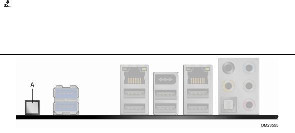
Back to BIOS Button
The back panel Back to BIOS button (Figure 4, A) duplicates the functionality of the BIOS configuration jumper with the following exceptions:
•It can only be used to force the board to power on to the BIOS Maintenance Menu using default values but it will retain all previously saved changes.
•It cannot be used to override passwords set in the BIOS.
•It cannot be used to invoke BIOS recovery mode.
The button glows red when it is activated.
21
Intel Desktop Board DX79SI Product Guide
 NOTE
NOTE
Using the Back to BIOS button does not set the board to the factory BIOS defaults. To restore settings to the factory defaults, use the <F9> key once BIOS setup mode is active.
Figure 4. Location of the Back to BIOS Button
Hardware Management
The hardware management features of Intel Desktop Board DX79SI enable the board to be compatible with the Wired for Management (WfM) specification. The board has several hardware management features including the following:
•Fan speed monitoring and control
•Thermal and voltage monitoring
•Chassis intrusion detection
Hardware Monitoring and Fan Speed Control
Hardware monitoring and fan speed control are based on the Nuvoton* Legacy I/O Controller, which provides the following:
•Processor and system ambient temperature monitoring
•Monitoring of power supply voltages to detect levels above and below acceptable values
•Chassis fan speed monitoring
•SMBus interface
Chassis Intrusion
The board supports a chassis security feature that detects if the chassis cover has been removed. The security feature uses a mechanical switch on the chassis that can be connected to the chassis intrusion header on the Desktop Board. See Figure 22 for the location and pinout of the chassis intrusion header.
22
Desktop Board Features
Power Management
Power management is implemented at several levels, including software support through the Advanced Configuration and Power Interface (ACPI) and the following hardware support:
•Power connectors
•Fan headers
•LAN wake capabilities
•Instantly Available PC technology (Suspend to RAM)
•+5 V standby power indicator LED
•Wake from USB
•Power Management Event signal (PME#) wakeup support
•WAKE# signal wake-up support
•Wake from Consumer IR
Software Support
ACPI
ACPI gives the operating system direct control over the power management and Plug and Play functions of a computer. The use of ACPI with the Desktop Board requires an operating system that provides full ACPI support.
Hardware Support
Power Connectors
ATX12V-compliant power supplies can turn off the computer power through system control. When an ACPI-enabled computer receives the correct command, the power supply removes all non-standby voltages.
When resuming from an AC power failure, the computer returns to the power state it was in before power was interrupted (either on or off). The computer’s response can be set by using the Last Power State feature in the BIOS Setup program’s Boot menu.
The Desktop Board has three power connectors. See Figure 25 on page 56 for the location of the power connectors.
Fan Headers
The function/operation of the fans is as follows:
•The fans are on when the computer is in the ACPI S0 state.
•The fans are off when the computer is in the ACPI S3, S4, or S5 state.
•Each fan header is wired to a tachometer input of the hardware monitoring and control device.
•All fan headers support closed-loop fan control that can adjust the fan speed or switch the fan on or off as needed.
•All fan headers have a +12 V DC connection.
23
Intel Desktop Board DX79SI Product Guide
The Desktop Board has a 4-pin processor fan header and three 4-pin chassis fan headers.
LAN Wake Capabilities
 CAUTION
For LAN wake capabilities, the 5 V standby line for the power supply must be capable of delivering adequate +5 V standby current. Failure to provide adequate standby current when using this feature can damage the power supply.
LAN wakeup capabilities enable remote wake-up of the computer through a network. The LAN subsystem monitors network traffic and upon detecting a Magic Packet* frame, it asserts a wake-up signal that powers up the computer.
Instantly Available PC Technology
 CAUTIONS
For Instantly Available PC technology, the 5 V standby line for the power supply must be capable of delivering adequate +5 V standby current. Failure to provide adequate standby current when using this feature can damage the power supply and/or effect ACPI S3 sleep state functionality.
Power supplies used with this Desktop Board must be able to provide enough standby current to support the standard Instantly Available (ACPI S3 sleep state) configuration. If the standby current necessary to support multiple wake events from the PCI and/or USB buses exceeds power supply capacity, the Desktop Board may lose register settings stored in memory.
Instantly Available PC technology enables the board to enter the ACPI S3 (Suspend-to- RAM) sleep state. While in the S3 sleep state, the computer will appear to be off. If the computer has a dual-colored power LED on the front panel, the sleep state is indicated by the LED turning amber. When signaled by a wake-up device or event, the computer quickly returns to its last known awake state.
The Desktop Board supports the PCI Bus Power Management Interface Specification. Add-in cards that support this specification can participate in power management and can be used to wake the computer.
+5 V Standby Power Indicator
 CAUTION
If the AC power has been switched off and the standby power indicator is still lit, disconnect the power cord before installing or removing any devices connected to the board. Failure to do so could damage the board and any attached devices.
24

Desktop Board Features
The Desktop Board’s standby power indicator, shown in Figure 5, is lit when there is standby power still present on the board even when the computer appears to be off. For example, when this LED is lit, standby power is still present at the memory module sockets and the PCI bus connectors.
Figure 5. Location of the Standby Power Indicator
For more information on standby current requirements for the Desktop Board, refer to the Technical Product Specification at http://www1 .intel.com/products/motherboard/index.htm
Wake from USB
 NOTE
NOTE
Wake from USB requires the use of a USB peripheral that supports Wake from USB and an operating system that supports Wake from USB.
USB bus activity wakes the computer from an ACPI S3 state.
25
Intel Desktop Board DX79SI Product Guide
PME# Signal Wake-up Support
When the PME# signal on the PCI bus is asserted, the computer wakes from an ACPI S3, S4, or S5 state.
WAKE# Signal Wake-up Support
When the WAKE# signal on the PCI Express bus is asserted, the computer wakes from an ACPI S3, S4, or S5 state.
Wake from Consumer IR
Consumer IR device activity wakes the computer from an ACPI S3, S4, or S5 state.
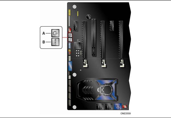
Onboard System Control Switches
The board contains the following lighted button switches that can be used to control board operation:
•Power
•Reset
Figure 6. Onboard System Control Switches
26

Desktop Board Features
Power Switch
The power button switch (see Figure 6, A) can be used to turn the desktop board on or off. This power button switch behaves the same as a chassis power switch connected via the front panel header. The onboard power button switch does not remove standby power. To turn off the computer using the onboard power button switch, keep it pressed down for three seconds.
Reset Switch
The reset button switch (see Figure 6, B) can be used to reset the desktop board. This power button switch behaves the same as a chassis reset switch connected via the front panel header. When the reset button switch is pressed, the board resets and runs the POST.
System Initialization/ Status LEDs
The Desktop Board provides LEDs that allow you to monitor your system’s progress through initialization and the BIOS POST (see Figure 7). There are also other board status LEDs that allow you to monitor other system activities.
Figure 7. Location of the Initialization/Status LEDs
27
Loading...