


Intel® NUC Board/Kit
NUC8v5PN & NUC8v7PN
Technical Product Specification
December 2019
Intel® NUC Board NUC8v5PN & NUC8v7PN may contain design defects or errors known as errata that may cause the product to deviate from published specifications. Current characterized errata, if any, are documented in Intel NUC Board NUC8v5PN & NUC8v7PN Specification Update.

Intel NUC Board/Kit NUC8v5PN & NUC8v7PN Technical Product Specification
Revision History
Revision |
Revision History |
Date |
|
|
|
1.0 |
First release of the Intel NUC Board/Kit NUC8v5PN & NUC8v7PN Technical |
November 2019 |
|
Product Specification |
|
|
|
|
1.1 |
Updated AA Revision to include TPM and TCM |
November 2019 |
|
2.2.4.4.1 – Updated Section |
|
|
|
|
1.2 |
1.5.1.4 – Added Display Emulation section |
December 2019 |
|
|
|
Disclaimer
This product specification applies to only the standard Intel NUC Board with BIOS identifier TBD.
INFORMATION IN THIS DOCUMENT IS PROVIDED IN CONNECTION WITH INTEL® PRODUCTS. NO LICENSE, EXPRESS OR IMPLIED, BY ESTOPPEL OR OTHERWISE, TO ANY INTELLECTUAL PROPERTY RIGHTS IS GRANTED BY THIS DOCUMENT. EXCEPT AS PROVIDED IN INTEL’S TERMS AND CONDITIONS OF SALE FOR SUCH PRODUCTS, INTEL ASSUMES NO LIABILITY WHATSOEVER, AND INTEL DISCLAIMS ANY EXPRESS OR IMPLIED WARRANTY, RELATING TO SALE AND/OR USE OF INTEL PRODUCTS INCLUDING LIABILITY OR WARRANTIES RELATING TO FITNESS FOR A PARTICULAR PURPOSE, MERCHANTABILITY, OR INFRINGEMENT OF ANY PATENT, COPYRIGHT OR OTHER INTELLECTUAL PROPERTY RIGHT. UNLESS OTHERWISE AGREED IN WRITING BY INTEL, THE INTEL PRODUCTS ARE NOT DESIGNED NOR INTENDED FOR ANY APPLICATION IN WHICH THE FAILURE OF THE INTEL PRODUCT COULD CREATE A SITUATION WHERE PERSONAL INJURY OR DEATH MAY OCCUR.
All Intel NUC Boards are evaluated as Information Technology Equipment (I.T.E.) for use in personal computers (PC) for installation in homes, offices, schools, computer rooms, and similar locations. The suitability of this product for other PC or embedded non-PC applications or other environments, such as medical, industrial, alarm systems, test equipment, etc. may not be supported without further evaluation by Intel.
Intel Corporation may have patents or pending patent applications, trademarks, copyrights, or other intellectual property rights that relate to the presented subject matter. The furnishing of documents and other materials and information does not provide any license, express or implied, by estoppel or otherwise, to any such patents, trademarks, copyrights, or other intellectual property rights.
Intel may make changes to specifications and product descriptions at any time, without notice.
Designers must not rely on the absence or characteristics of any features or instructions marked “reserved” or “undefined.” Intel reserves these for future definition and shall have no responsibility whatsoever for conflicts or incompatibilities arising from future changes to them.
Intel processor numbers are not a measure of performance. Processor numbers differentiate features within each processor family, not across different processor families: Go to:
Learn About Intel® Processor Numbers
Intel NUC may contain design defects or errors known as errata, which may cause the product to deviate from published specifications. Current characterized errata are available on request.
Contact your local Intel sales office or your distributor to obtain the latest specifications before placing your product order.
Intel, the Intel logo, Intel NUC and Intel Core are trademarks of Intel Corporation in the U.S. and/or other countries. * Other names and brands may be claimed as the property of others.
Copyright © 2019 Intel Corporation. All rights reserved.
iv
Board Identification Information
Basic Intel® NUC Board NUC8v5PNB & NUC8v7PNB Identification Information
AA Revision |
BIOS Revision |
Notes |
|
|
|
K59971-xxx |
PNWHL57.xxxx |
1,2 |
|
|
|
K66222-xxx |
PNWHL57.xxxx |
1,3 |
|
|
|
K59997-xxx |
PNWHL57.xxxx |
1,4 |
|
|
|
K66242-xxx |
PNWHL57.xxxx |
1,5 |
|
|
|
Notes:
1.The AA number is found on a small label on the component side of the board.
2.The Intel® Core™ i7-8665U processor with TPM is used on this AA revision consisting of the following component:
3.The Intel® Core™ i7-8665U processor with TCM is used on this AA revision consisting of the following component:
4.The Intel® Core™ i5-8365U processor with TPM is used on this AA revision consisting of the following component:
5.The Intel® Core™ i5-8365U processor with TCM is used on this AA revision consisting of the following component:
Device |
Stepping |
S-Spec Numbers |
|
|
|
Intel Core i5 |
V0 |
SRF9Z |
|
|
|
Intel Core i7 |
V0 |
SRF9W |
|
|
|
Production Identification Information
Intel® NUC Products NUC8v5PN & NUC8v7PN{x} Identification Information
Product Name |
Intel® NUC Board |
|
|
NUC8v5PNK |
|
|
|
NUC8v5PNH |
NUC8v5PNB |
|
|
NUC8v5PNB |
|
|
|
NUC8v7PNK |
|
|
|
NUC8v7PNH |
NUC8v7PNB |
|
|
NUC8v7PNB |
|
|
|
Specification Changes or Clarifications
The table below indicates the Specification Changes or Specification Clarifications that apply to the Intel NUC Board/Kit NUC8v5PN & NUC8v7PN.
Specification Changes or Clarifications
Date |
Type of Change |
Description of Changes or Clarifications |
|
|
|
|
|
|
Errata
Current characterized errata, if any, are documented in a separate Specification Update. See http://www.intel.com/content/www/us/en/nuc/overview.html for the latest documentation.
v

Intel NUC Board/Kit NUC8v5PN & NUC8v7PN Technical Product Specification
Preface
This Technical Product Specification (TPS) specifies the board layout, components, connectors, power and environmental requirements, and the BIOS for Intel® NUC Board/Kits NUC8v5PN & NUC8v7PN. Some features are only available on Kit SKUs.
Intended Audience
The TPS is intended to provide detailed, technical information about Intel® NUC Board/Kit NUC8v5PN & NUC8v7PN and its components to the vendors, system integrators, and other engineers and technicians who need this level of information. It is specifically not intended for general audiences.
What This Document Contains
Chapter |
Description |
|
|
1 |
A description of the hardware used on Intel® NUC Board NUC8v5PNB & NUC8v7PNB |
|
|
2 |
A map of the resources of the Intel® NUC Board |
|
|
3 |
The features supported by the BIOS Setup program |
|
|
4 |
A description of the BIOS error messages, beep codes, and POST codes |
|
|
5 |
Regulatory compliance and battery disposal information |
|
|
Typographical Conventions
This section contains information about the conventions used in this specification. Not all of these symbols and abbreviations appear in all specifications of this type.
Notes, Cautions, and Warnings
NOTE |
Notes call attention to important information.
CAUTION
Cautions are included to help you avoid damaging hardware or losing data.
vi

Other Common Notation
# |
Used after a signal name to identify an active-low signal (such as USBP0#) |
|
|
GB |
Gigabyte (1,073,741,824 bytes) |
|
|
GB/s |
Gigabytes per second |
|
|
Gb/s |
Gigabits per second |
|
|
KB |
Kilobyte (1024 bytes) |
|
|
Kb |
Kilobit (1024 bits) |
|
|
kb/s |
1000 bits per second |
|
|
MB |
Megabyte (1,048,576 bytes) |
|
|
MB/s |
Megabytes per second |
|
|
Mb |
Megabit (1,048,576 bits) |
|
|
Mb/s |
Megabits per second |
|
|
TDP |
Thermal Design Power |
|
|
xxh |
An address or data value ending with a lowercase h indicates a hexadecimal value. |
|
|
x.x V |
Volts. Voltages are DC unless otherwise specified. |
|
|
x.x A |
Amperes. |
*This symbol is used to indicate third-party brands and names that are the property of their respective owners.
vii

Contents
Revision History.............................................................................................................. |
iv |
Disclaimer ................................................................................................................................................................. |
iv |
Board Identification Information...................................................................................................................... |
v |
Errata............................................................................................................................................................................ |
v |
Preface .............................................................................................................................. |
|
vi |
|
Intended Audience................................................................................................................................................ |
vi |
||
What This Document Contains........................................................................................................................ |
vi |
||
Typographical Conventions .............................................................................................................................. |
vi |
||
Contents ........................................................................................................................... |
|
ix |
|
1 Product Description ............................................................................................... |
13 |
||
1.1 |
Overview ...................................................................................................................................................... |
13 |
|
|
1.1.1 |
Feature Summary .................................................................................................................. |
13 |
|
1.1.2 |
Board Layout (Top) ............................................................................................................... |
15 |
|
1.1.3 |
Board Layout (Bottom) ........................................................................................................ |
16 |
|
1.1.4 |
Block Diagram......................................................................................................................... |
17 |
1.2 |
Online Support.......................................................................................................................................... |
19 |
|
1.3 |
Processor..................................................................................................................................................... |
19 |
|
1.4 |
System Memory........................................................................................................................................ |
20 |
|
1.5 |
Processor Graphics Subsystem.......................................................................................................... |
21 |
|
|
1.5.1 |
Integrated Graphics .............................................................................................................. |
21 |
1.6 |
USB................................................................................................................................................................. |
|
25 |
1.7 |
SATA Interface........................................................................................................................................... |
26 |
|
|
1.7.1 |
AHCI Mode................................................................................................................................ |
26 |
|
1.7.2 |
NVMe........................................................................................................................................... |
26 |
|
1.7.3 |
Intel® Rapid Storage Technology / SATA RAID ......................................................... |
26 |
|
1.7.4 |
Intel® Next Generation Storage Acceleration............................................................. |
27 |
1.8 |
Real-Time Clock Subsystem................................................................................................................ |
28 |
|
1.9 |
Audio Subsystem Software.................................................................................................................. |
28 |
|
|
1.9.1 |
Audio Subsystem Software ............................................................................................... |
28 |
1.10 LAN Subsystem......................................................................................................................................... |
29 |
||
|
1.10.1 |
Intel® I219LM Gigabit Ethernet Controller .................................................................. |
29 |
|
1.10.2 |
RJ-45 LAN Connector with Integrated LEDs.............................................................. |
29 |
|
1.10.3 |
Wireless Network Module.................................................................................................. |
30 |
1.11 Hardware Management Subsystem ................................................................................................. |
30 |
||
|
1.11.1 |
Hardware Monitoring ........................................................................................................... |
31 |
|
1.11.2 |
Fan Monitoring........................................................................................................................ |
31 |
|
1.11.3 |
Thermal Solution................................................................................................................... |
31 |
1.12 Power Management ................................................................................................................................ |
32 |
||
ix
Intel NUC Board/Kit NUC8v5PN & NUC8v7PN Technical Product Specification
|
|
1.12.1 |
ACPI............................................................................................................................................. |
32 |
|
|
1.12.2 |
Hardware Support................................................................................................................. |
34 |
|
1.13 |
Intel® Security and Manageability Technologies......................................................................... |
36 |
|
|
|
1.13.1 |
Intel® vPro™ Technology..................................................................................................... |
36 |
2 |
Technical Reference............................................................................................... |
41 |
||
|
2.1 |
Memory Resources.................................................................................................................................. |
41 |
|
|
|
2.1.1 |
Addressable Memory........................................................................................................... |
41 |
|
2.2 |
Connectors and Headers....................................................................................................................... |
41 |
|
|
|
2.2.1 |
Front Panel Connectors...................................................................................................... |
42 |
|
|
2.2.2 |
Back Panel Connectors ....................................................................................................... |
42 |
|
|
2.2.3 |
Connectors and Headers (Top)........................................................................................ |
43 |
|
|
2.2.4 |
Connectors and Headers (Bottom)................................................................................. |
44 |
|
2.3 |
BIOS Security Jumper ............................................................................................................................ |
54 |
|
|
2.4 |
Mechanical Considerations.................................................................................................................. |
56 |
|
|
|
2.4.1 |
Form Factor.............................................................................................................................. |
56 |
|
2.5 |
Electrical Considerations ...................................................................................................................... |
57 |
|
|
|
2.5.1 |
Power Supply Considerations.......................................................................................... |
57 |
|
|
2.5.2 |
Fan Header Current Capability......................................................................................... |
58 |
|
2.6 |
Thermal Considerations........................................................................................................................ |
58 |
|
|
2.7 |
Reliability ..................................................................................................................................................... |
64 |
|
|
2.8 |
Environmental ........................................................................................................................................... |
64 |
|
3 Overview of BIOS Features................................................................................... |
67 |
|||
|
3.1 |
Introduction................................................................................................................................................ |
67 |
|
|
3.2 |
BIOS Flash Memory Organization ..................................................................................................... |
67 |
|
|
3.3 |
System Management BIOS (SMBIOS).............................................................................................. |
67 |
|
|
3.4 |
Legacy USB Support ............................................................................................................................... |
68 |
|
|
3.5 |
BIOS Updates............................................................................................................................................. |
68 |
|
|
|
3.5.1 |
Language Support................................................................................................................. |
69 |
|
|
3.5.2 |
BIOS Recovery......................................................................................................................... |
69 |
|
3.6 |
Boot Options.............................................................................................................................................. |
70 |
|
|
|
3.6.1 |
Network Boot........................................................................................................................... |
70 |
|
|
3.6.2 |
Booting Without Attached Devices................................................................................ |
70 |
|
|
3.6.3 |
Boot Device Selection During POST.............................................................................. |
70 |
|
|
3.6.4 |
Power Button Menu.............................................................................................................. |
70 |
|
3.7 |
Hard Disk Drive Password Security Feature.................................................................................. |
72 |
|
|
3.8 |
BIOS Security Features .......................................................................................................................... |
72 |
|
4 |
Error Messages ........................................................................................................ |
74 |
||
|
4.1 |
BIOS Error Messages............................................................................................................................... |
74 |
|
5 Regulatory Compliance and Battery Disposal Information .......................... |
75 |
|||
|
5.1 |
Regulatory Compliance.......................................................................................................................... |
75 |
|
|
|
5.1.1 |
Safety Standards.................................................................................................................... |
75 |
x
|
|
Contents |
5.1.2 |
European Union Declaration of Conformity Statement........................................ |
75 |
5.1.3 |
EMC Regulations .................................................................................................................... |
76 |
5.1.4 |
e-Standby and ErP Compliance....................................................................................... |
78 |
5.1.5 |
Regulatory Compliance Marks (Board Level)............................................................. |
79 |
5.2 Battery Disposal Information .............................................................................................................. |
80 |
|
Figures |
|
|
Figure 1. Major Board Components (Top) ....................................................................................................... |
15 |
|
Figure 2. Major Board Components (Bottom) ................................................................................................ |
16 |
|
Figure 3. Block Diagram........................................................................................................................................... |
18 |
|
Figure 4. Memory Channel and SO-DIMM Configuration.......................................................................... |
21 |
|
Figure 5. eDP Connector on Bottom-side of the Board............................................................................. |
23 |
|
Figure 6. LAN Connector LED Locations........................................................................................................... |
29 |
|
Figure 7. Thermal Solution and Fan Header................................................................................................... |
31 |
|
Figure 8. Location of the Standby Power LED ............................................................................................... |
35 |
|
Figure 9. Front Panel Connectors........................................................................................................................ |
42 |
|
Figure 10. Back Panel Connectors ...................................................................................................................... |
42 |
|
Figure 11. Connectors and Headers (Top)....................................................................................................... |
43 |
|
Figure 12. Connectors and Headers (Bottom) ............................................................................................... |
44 |
|
Figure 13. Connection Diagram for Front Panel Header (2.0 mm Pitch) ............................................ |
51 |
|
Figure 14. Connection Diagram for the Internal Power Supply Connector....................................... |
53 |
|
Figure 15. Location of the BIOS Security Jumper ........................................................................................ |
54 |
|
Figure 17. Board Dimensions................................................................................................................................ |
56 |
|
Figure 18. Board Height Dimensions ................................................................................................................. |
57 |
|
Figure 19. Localized High Temperature Zones ............................................................................................. |
60 |
|
Figure 20. Installation Area of the Thermal Pad on Tall Chassis ........................................................... |
61 |
|
Figure 21. Installation Area of the Thermal Pad on Slim Chassis.......................................................... |
62 |
|
Tables |
|
|
Table 1. Feature Summary..................................................................................................................................... |
13 |
|
Table 2. Components Shown in Figure 1.......................................................................................................... |
15 |
|
Table 3. Components Shown in Figure 2......................................................................................................... |
17 |
|
Table 4. LAN Connector LED States................................................................................................................... |
30 |
|
Table 5. Effects of Pressing the Power Switch............................................................................................... |
32 |
|
Table 6. Power States and Targeted System Power ................................................................................... |
33 |
|
Table 7. Wake-up Devices and Events.............................................................................................................. |
34 |
|
Table 8. Connectors and Headers Shown in Figure 11.............................................................................. |
43 |
|
Table 9. Connectors and Headers Shown in Figure 12.............................................................................. |
45 |
|
Table 10. SATA Power Header (1.25 mm pitch)............................................................................................ |
46 |
|
xi
Intel NUC Board/Kit NUC8v5PN & NUC8v7PN Technical Product Specification |
|
Table 11. Internal USB 2.0 Header (1.25 mm pitch)..................................................................................... |
46 |
Table 12. Internal USB 3.0 Header (1.25 mm pitch)..................................................................................... |
47 |
Table 13. Serial Port Header (1.25 mm pitch)................................................................................................. |
47 |
Table 14. M.2 2280 Module (Mechanical Key M) Connector .................................................................... |
47 |
Table 15. M.2 2230 Module (Mechanical Key E) Connector .................................................................... |
49 |
Table 16. 40-Pin eDP Connector......................................................................................................................... |
50 |
Table 17. Front Panel Header (2.0 mm Pitch)................................................................................................ |
51 |
Table 18. States for a One-Color Power LED................................................................................................. |
52 |
Table 19. States for a Dual-Color Power LED ................................................................................................ |
52 |
Table 20. 12-24 V Internal Power Supply Connector ................................................................................ |
53 |
Table 21. BIOS Security Jumper Settings........................................................................................................ |
54 |
Table 22. Power Budget for Assessing the DC-to-DC Circuit’s Power Rating (worst case: |
|
Embedded board in 3rd party chassis) ...................................................................................................... |
57 |
Table 23 lists the current capability of the fan headers............................................................................. |
58 |
Table 23. Fan Header Current Capability......................................................................................................... |
58 |
Table 25. Thermal Considerations for Components................................................................................... |
63 |
Table 26. Tcontrol Values for Components ................................................................................................... |
63 |
Table 27. Environmental Specifications........................................................................................................... |
64 |
Table 28. Acceptable Drives/Media Types for BIOS Recovery ............................................................... |
69 |
Table 29. Boot Device Menu Options................................................................................................................ |
70 |
Table 30. Master Key and User Hard Drive Password Functions........................................................... |
72 |
Table 31. Supervisor and User Password Functions................................................................................... |
73 |
Table 32. BIOS Error Messages............................................................................................................................ |
74 |
Table 33. Safety Standards.................................................................................................................................... |
75 |
Table 34. EMC Regulations .................................................................................................................................... |
77 |
Table 35. Regulatory Compliance Marks ......................................................................................................... |
79 |
xii
1 Product Description
1.1Overview
1.1.1Feature Summary
Table 1 summarizes the major features of Intel® NUC Board NUC8v5PNB & NUC8v7PNB.
Table 1. Feature Summary
Form Factor |
4.0 inches by 4.0 inches (101.60 millimeters by 101.60 millimeters) |
|
|
Processor |
Intel® NUC Board NUC8v5PNB has a soldered-down 8th generation Intel® Core™ i5-8365U |
|
quad-core processor with up to 25 W TDP |
|
― Intel® UHD Graphics 620 |
|
― Integrated memory controller |
|
― Integrated PCH |
|
Intel® NUC Board NUC8v7PNB has a soldered-down 8th generation Intel® Core™ i7-8665U |
|
quad-core processor with up to 25 W TDP |
|
― Intel® UHD Graphics 620 |
|
― Integrated memory controller |
|
― Integrated PCH |
|
|
Memory |
Two 260-pin 1.2 V DDR4 SDRAM Small Outline Dual Inline Memory Module (SO-DIMM) |
|
sockets |
|
― Support for DDR4 1866/2133/2400 MHz SO-DIMMs |
|
― Support for 4 Gb, 8 Gb, and 16 Gb memory technology |
|
― Support for up to 64 GB of system memory with two SO-DIMMs using 16Gb memory |
|
technology |
|
― Support for non-ECC memory |
|
― Support for 1.2 V low voltage JEDEC memory only |
|
Note: 2 Gb memory technology (SDRAM Density) is not compatible |
|
|
Graphics |
Integrated graphics support for processors with Intel® Graphics Technology: |
|
― Two High Definition Multimedia Interface* 2.0a (HDMI*) back panel connectors |
|
― Flat panel displays via the internal Embedded DisplayPort* 1.4 (eDP) connector |
|
|
Audio |
Intel® High Definition (Intel® HD) Audio via the HDMI v2.0a interface through the processor |
|
|
Storage |
SATA ports: |
|
― One SATA 6.0 Gb/s port (blue) |
|
― One SATA 6.0 Gb/s port is reserved for an M.2 2280 module |
|
Note: Intel® NUC Board NUC8v5PNB & NUC8v7PNB supports key type M (PCI Express* |
|
x1/x2/x4 and SATA) |
|
|
Peripheral Interfaces |
USB 3.0 ports: |
|
― Two ports are implemented with external front panel connectors (blue) |
|
― One port is implemented with external back panel connectors (blue) |
|
― One port is implemented with an internal 1x10 1.25mm pitch header (white) |
|
USB 2.0 ports: |
|
― One port is implemented with external back panel connectors (black) |
|
― Two ports via two single-port internal 1x4 1.25 mm pitch headers (white) |
|
― One port is reserved for an M.2 2230 Module (key type E) |
|
Serial Port 1x9 1.25mm pitch header (black) |
|
|
13
Intel NUC Board/Kit NUC8v5PN & NUC8v7PN Technical Product Specification
Table 1. Feature Summary (continued)
Expansion Capabilities |
One M.2 Module supporting M.2 2280 (key type M) |
|
One M.2 Module supporting M.2 2230 (key type E) for Wireless Only |
|
|
BIOS |
Intel® BIOS resident in the Serial Peripheral Interface (SPI) Flash device |
|
Support for Advanced Configuration and Power Interface (ACPI), Plug and Play, and System |
|
Management BIOS (SMBIOS) |
|
|
LAN |
Gigabit (10/100/1000 Mb/s) LAN subsystem using the Intel® I219LM Gigabit Ethernet |
|
Controller |
|
|
Hardware Monitor |
Hardware monitoring subsystem including: |
Subsystem |
Voltage sense to detect out of range power supply voltages |
|
|
|
Thermal sense to detect out of range thermal values |
|
One processor fan header |
|
Fan sense input used to monitor fan activity |
|
Fan speed control |
|
|
Wireless (Kit only) |
Intel® Dual Band Wireless-AC vPro 9560 |
|
― 802.11ac, Dual Band, 2x2 Wi-Fi + Bluetooth v5 |
|
― Maximum Transfer speed up to 1.73 Gbps |
|
― Supports CNVi and PCIE |
|
|
Intel® vPro™ |
Intel® Active Management Technology (out-of-band remote power on/off/reboot, Serial |
Technologies |
over LAN, IDE-R) |
|
Wireless Intel® AMT Desktop and Mobile Architecture for System Hardware: DASH v1.1 |
|
compliance |
|
Intel Remote Manageability (out-of-band Remote KVM) |
|
Intel® vPro™ brand eligibility |
|
Intel® Transparent Supply Chain |
|
|
14

Product Description
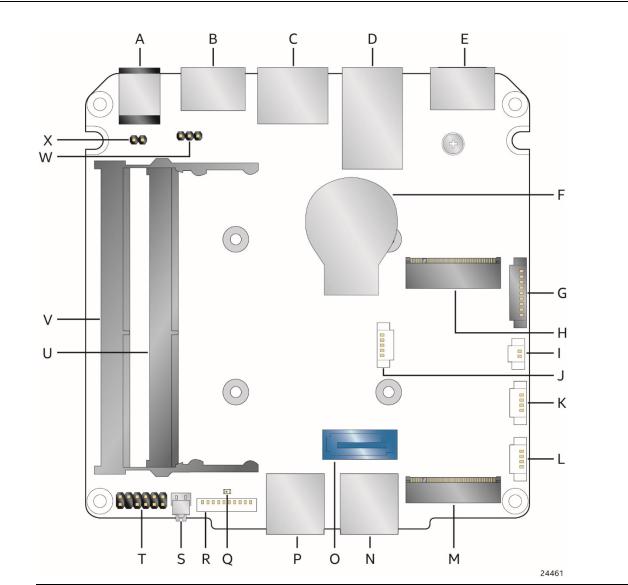
1.1.2Board Layout (Top)
Figure 1 shows the location of the major components on the top-side of Intel NUC Board NUC8v5PNB & NUC8v7PNB.
Figure 1. Major Board Components (Top)
Table 2. Components Shown in Figure 1
Item from Figure 1 |
Description |
A |
Thermal Solution |
|
|
B |
Processor Fan Header |
|
|
C |
DC Internal Power Connector |
|
|
D |
eDP Connector |
|
|
15
Intel NUC Board/Kit NUC8v5PN & NUC8v7PN Technical Product Specification
1.1.3Board Layout (Bottom)
Figure 2 shows the location of the major components on the bottom-side of Intel NUC Board NUC8v5PNB & NUC8v7PNB.
Figure 2. Major Board Components (Bottom)
16
|
|
Product Description |
Table 3. Components Shown in Figure 2 |
||
|
|
|
|
Item from Figure 2 |
Description |
|
|
|
|
A |
12-24 V DC Input Jack |
|
|
|
|
B |
HDMI 2.0a Port 1 with HDCP 2.2 Support and Built-In CEC Support |
|
|
|
|
C |
LAN Connector |
|
|
|
|
D |
Back Panel USB 3.0 / USB 2.0 |
|
|
|
|
E |
HDMI 2.0a Port 2 / Thunderbolt 3 Port |
|
|
|
|
F |
CMOS Battery |
|
|
|
|
G |
Serial Port Header |
|
|
|
|
H |
M.2 2230 Module Connector (Key Type E) (Wireless card on Kit only) |
|
|
|
|
I |
Battery Header |
|
|
|
|
J |
SATA Power Header |
|
|
|
|
K |
USB 2.0 Header |
|
|
|
|
L |
USB 2.0 Header |
|
|
|
|
M |
M.2 2280 Module Connector (Key Type M) |
|
|
|
|
N |
Front Panel USB 3.0 |
|
|
|
|
O |
SATA 6.0 Gb/s Connector |
|
|
|
|
P |
Front Panel USB 3.0 |
|
|
|
|
Q |
Standby Power LED |
|
|
|
|
R |
USB 3.0 Header |
|
|
|
|
S |
Front Panel Power Button |
|
|
|
|
T |
Front Panel Header |
|
|
|
|
U |
DDR4 SO-DIMM 0 Socket |
|
|
|
|
V |
DDR4 SO-DIMM 1 Socket |
|
|
|
|
W |
BIOS Security Header |
|
|
|
|
X |
Intel® Management Engine BIOS Extension (Intel® MEBX) Reset Header |
|
|
|
1.1.4Block Diagram
Figure 3 is a block diagram of the major functional areas of the board.
17

Intel NUC Board/Kit NUC8v5PN & NUC8v7PN Technical Product Specification
Figure 3. Block Diagram
18

1.2Online Support
To find information about…
Intel NUC Board/Kit NUC8v5PN &
NUC8v7PN
Intel NUC Board/Kit Support
High level details for Intel NUC Board/Kit NUC8v5PN & NUC8v7PN
BIOS and driver updates
Tested memory
Integration information
Processor datasheet
Regulatory documentation
Product Description
Visit this World Wide Web site:
http://www.intel.com/NUC
http://www.intel.com/NUCSupport
https://ark.intel.com/content/www/us/en/ark/search.html?_charset_=UT F-8&q=provo%20canyon
https://downloadcenter.intel.com/search?keyword=nuc8v%pn/search?k eyword=nuc8v%pn
http://www.intel.com/NUCSupport
http://www.intel.com/NUCSupport
https://ark.intel.com/content/www/us/en/ark/search.html?_charset_=UT F-8&q=provo%20canyon
https://www.intel.com/content/www/us/en/support/articles/000055571. html
1.3Processor
Intel NUC Board NUC8v5PNB has a soldered-down 8th generation Intel Core i5-8365U quad-core processor with up to 25 W TDP:
•Intel® UHD Graphics 620
•Integrated memory controller
•Integrated PCH
NUC8v7PNB has a soldered-down 8th generation Intel Core i7-8655U quad-core processor with up to 25 W TDP:
•Intel® UHD Graphics 620
•Integrated memory controller
•Integrated PCH
NOTE |
There are specific requirements for providing power to the processor. Refer to Section 2.5.1 on page 57 for information on power supply requirements.
19

Intel NUC Board/Kit NUC8v5PN & NUC8v7PN Technical Product Specification
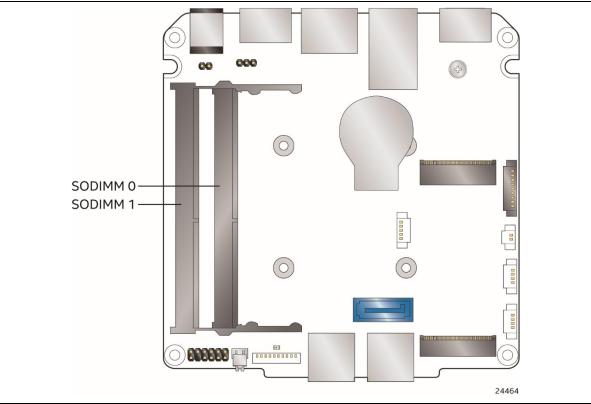
1.4System Memory
The board has two 260-pin SO-DIMM sockets and supports the following memory features:
•1.2 V DDR4 SDRAM SO-DIMMs with gold plated contacts
•Two independent memory channels with interleaved mode support
•Unbuffered, single-sided or double-sided SO-DIMMs
•64 GB maximum total system memory (with 16 Gb memory technology)
•Minimum recommended total system memory: 2048 MB
•Non-ECC SO-DIMMs
•Serial Presence Detect
•DDR4 1866/2133/2400 MHz SDRAM SO-DIMMs
•Supports 4 Gb, 8 Gb, and 16 Gb memory technology (SDRAM Density)
NOTE |
To be fully compliant with all applicable DDR SDRAM memory specifications, the board should be populated with SO-DIMMs that support the Serial Presence Detect (SPD) data structure. This allows the BIOS to read the SPD data and program the chipset to accurately configure memory settings for optimum performance. If non-SPD memory is installed, the BIOS will attempt to correctly configure the memory settings, but performance and reliability may be impacted or the SO-DIMMs may not function under the determined frequency.
NOTE
Intel NUC Board NUC8v5PNB & NUC8v7PNB supports only 4 Gb, 8 Gb, and 16 Gb memory technologies (also referred to as “SDRAM density”).
For information about… |
Refer to: |
|
|
Tested Memory |
http://www.intel.com/NUCSupport |
|
|
20
Product Description
Figure 4 illustrates the memory channel and SO-DIMM configuration.
Figure 4. Memory Channel and SO-DIMM Configuration
1.5Processor Graphics Subsystem
The board supports graphics through Intel® UHD Graphics 620.
1.5.1Integrated Graphics
The board supports integrated graphics via the processor.
1.5.1.1Intel® High Definition (Intel® HD) Graphics
The Intel® UHD Graphics 620 controller features the following:
•3D Features
DirectX* 12 support
OpenGL* 4.5 support
•Display
Supports eDP flat panel displays up to 3840 x 2160 at 60 Hz
Supports HDMI displays up to 4096 x 2160 at 60 Hz
Supports Type-C and Thunderbolt 3 Display, multiplexed on a first-come, first served basis w/ DP out.
21

Intel NUC Board/Kit NUC8v5PN & NUC8v7PN Technical Product Specification
•Next Generation Intel® Clear Video Technology HD support is a collection of video playback and enhancement features that improve the end user’s viewing experience
•Encode/transcode HD content
•Playback of high definition content including Blu-ray* disc
•Superior image quality with sharper, more colorful images
•DirectX* Video Acceleration (DXVA) support for accelerating video processing
•Full AVC/VC1/MPEG2/HEVC/VP8/JPEG HW Decode
•Intel HD Graphics with Advanced Hardware Video Transcoding (Intel® Quick Sync Video)
•HDR 10 (High Dynamic Range 10 bit)
•HDCP (High-bandwidth Digital Content Protection) 2.2
NOTE |
Intel Quick Sync Video is enabled by an appropriate software application.
1.5.1.2High Definition Multimedia Interface* (HDMI*)
The HDMI ports are HDMI 2.0a specification compliant and support standard, enhanced, or high definition video, plus multi-channel digital audio on a single cable. The port is compatible with all ATSC and DVB HDTV standards and supports thirty-two full range channels of lossless audio formats. The system can support up to two displays at the maximum supported resolution of 4096 x 2160 @ 60 Hz, 24bpp.
For information about |
Refer to |
|
|
HDMI technology |
http://www.hdmi.org |
|
|
1.5.1.2.1Integrated Audio Provided by the HDMI Interfaces
The following audio technologies are supported by the HDMI 2.0a interface:
•192kHz/16-bit or 176.4 kHz/24-bit, 32 Channel
1.5.1.2.2High-bandwidth Digital Content Protection (HDCP)
HDMI Port 1 supports HDCP 2.2. HDCP is the technology for protecting high definition content against unauthorized copy or interception between a source (computer, digital set top boxes, etc.) and the sink (panels, monitor, and TVs). The PCH supports HDCP 2.2 for content protection over wired displays.
1.5.1.3Flat Panel Display Interfaces
The board supports flat panel displays via the Embedded DisplayPort interface. Figure 5 shows the flat panel connector on the bottom-side of the board.
22
Product Description
A
Item |
Description |
|
|
A |
Embedded DisplayPort Connector |
Figure 5. eDP Connector on Bottom-side of the Board
1.5.1.3.1Embedded DisplayPort (eDP) Interface
The Embedded DisplayPort 1.4 (eDP) flat panel display interface supports the following:
•Maximum resolution of 3840 x 2160 at 60 Hz
•4-lane bandwidth at 5.4 Gb/s
•Multiple EDID data source capability (panel, predefined, and custom payloads)
•3.3V flat panel display voltage
•0.6A of maximum backlight current capability
•Backlight power voltage same as NUC board DC power source (No backlight power if DC in >21V)
•Board connector used is I-PEX-20455-040E-12, or compatible
1.5.1.3.2Configuration Modes
Video mode configuration for eDP displays is supported as follows:
•Panel: automatic panel identification via Extended Display Identification Data (EDID) for panels with onboard EDID support
•Predefined: panel selection from common predefined panel types
23

Intel NUC Board/Kit NUC8v5PN & NUC8v7PN Technical Product Specification
•Custom payloads: custom EDID payload installation for ultimate parameter flexibility, allowing custom definition of EDID data on panels without onboard EDID
In addition, BIOS setup provides the following configuration parameters for internal flat panel displays:
•Color Depth: allows the system integrator to select whether the panel is 24 bpp with VESA or JEIDA color mapping, or 18 bpp.
•eDP Interface Type: allows the system integrator to select whether the eDP panel is a singlelane, dual-lane, or quad-lane display.
•eDP Data Rate: allows the system integrator to select whether the eDP panel runs at 1.62 Gb/s, 2.7 Gb/s, or 5.4 Gb/s.
•Inverter Frequency and Polarity: allows the system integrator to set the operating frequency and polarity of the panel inverter board.
•Maximum and Minimum Inverter Current Limit (%): allows the system integrator to set maximum PWM%, as appropriate, according to the power requirements of the internal flat panel display and the selected inverter board.
NOTE |
Support for flat panel display configuration complies with the following:
1.Internal flat panel display settings will be preserved across BIOS updates.
2.Backlight inverter voltage option “Vin” refers to board input voltage as provided to board power input connector.
24

Product Description
1.5.1.4Display Emulation
Display emulation is supported using the HDMI ports so that the system may be remotely accessed in a headless configuration or be capable of tolerating display connectivity interruptions without the operating system redetecting and rearranging the overall display layout. The display emulation feature may be enabled in BIOS Setup (Advanced → Video → “Display Emulation” drop down menu) with the following options:
•“No display emulation” (default selection): the system operates normally.
•“Virtual display emulation”: provides a 1280x1024 virtual display when no displays are connected to the system and provides an additional 1280x1024 virtual display if one display is attached to the system. (If two display are attached to the system these displays will be enabled and no virtual displays will be provided).
•“Persistent display emulation”: emulates that both displays are always connected to the system no matter their actual connection status. The EDID information from each display will remain programmed through S3, S4, and S5 power states until the feature is disabled.
•When “Persistent display emulation” is enabled another drop-down menu (“Inconsistent Display Device”) will become visible that allows the user to select the behavior of the system when the display device EDID is inconsistent with the EDID stored by the system.
▪“Block boot” (default selection): the BIOS will display a warning message with options and will wait indefinitely for a user selection.
▪“Countdown”: the BIOS will display a warning message with options and will wait 10 seconds before booting.
NOTE
“Persistent display emulation” is not compatible with HDCP 2.2 displays.
When using “Persistent display emulation” it would be expected behavior for the system not to properly drive displays different than those connected when the feature was enabled, as the EDID parameters of the initially connected displays are still being driven by the system. A power cycle (AC power loss) is required to retrain the system with a different display configuration
1.6USB
The board supports eight USB ports. All eight ports are high-speed, full-speed, and low-speed capable. The port arrangement is as follows:
•USB 3.0 ports:
Two ports are implemented with external front panel connectors (blue)
One port is implemented with external back panel connectors (blue)
One port is implemented with a 1x10 1.25mm internal header (white)
•USB 2.0 ports:
One port is implemented with external back panel connectors (black)
Two ports via two single-port internal 1x4 1.25 mm pitch headers (white)
One port is reserved for the M.2 2230 Module Connector (Key Type E) (Wireless card on Kit only)
25

Intel NUC Board/Kit NUC8v5PN & NUC8v7PN Technical Product Specification
NOTE |
Computer systems that have an unshielded cable attached to a USB port may not meet FCC Class B requirements, even if no device is attached to the cable. Use a shielded cable that meets the requirements for full-speed devices.
For information about |
Refer to |
|
|
The location of the front panel USB headers |
Figure 9, page 42 |
|
|
The location of the USB connectors on the back panel |
Figure 10, page 42 |
|
|
The location of the internal connectors |
Figure 12, page 44 |
|
|
1.7SATA Interface
The board provides the following SATA interfaces:
•One internal M.2 SATA port supporting M.2 2280 (key type M) modules
•One SATA 6.0 Gb/s port (blue)
The PCH provides independent SATA ports with a theoretical maximum transfer rate of 6 Gb/s. A point-to-point interface is used for host to device connections.
1.7.1AHCI Mode
The board supports AHCI storage mode.
NOTE |
In order to use AHCI mode, AHCI must be enabled in the BIOS. Microsoft* Windows* 10 includes the necessary AHCI drivers without the need to install separate AHCI drivers during the operating system installation process; however, it is always good practice to update the AHCI drivers to the latest available by Intel.
1.7.2NVMe
The board supports M.2 NVM Express* (NVMe) drives. NVMe is an optimized, high-performance scalable host controller interface designed to utilize PCIe-based solid-state storage. NVMe is designed to provide efficient access to storage devices built with non-volatile memory, from current NAND flash technology to future, higher performing persistent memory technologies like Optane. NVMe is designed to meet serial bandwidth requirements and very high IOPs. It is based on PCIe Gen 3 and can deliver up to 4GB/s bandwidth. Current NVMe is based on version 1.3 of the specification.
1.7.3Intel® Rapid Storage Technology / SATA RAID
The PCH supports Intel® Rapid Storage Technology, providing both AHCI and integrated RAID functionality. The RAID capability provides high-performance RAID 0 and 1 functionality on all SATA ports. Other RAID features include hot spare support, SMART alerting, and RAID 0 auto replace. Software components include an Option ROM for pre-boot configuration and boot
26

Product Description
functionality, a Microsoft Windows compatible driver, and a user interface for configuration and management of the RAID capability of the PCH.
NOTE |
Intel Rapid Storage Technology / SATA RAID is only supported if an M.2 SATA SSD module is used with the onboard SATA interface. RAID is not available with an M.2 NVMe SSD module and onboard SATA interface. Supported on chassis with 2.5 inch SATA HDD capability.
1.7.4Intel® Next Generation Storage Acceleration
Intel® Next Generation Storage Acceleration with Intel® Optane™ Technology is a disk caching solution that can provide improved computer system performance with improved power savings. It allows configuration of a computer system with the advantage of having HDDs for maximum storage capacity and with Intel® Optane™ Technology for improved system performance.
Supported on chassis with 2.5 inch SATA HDD capability.
For more information on Intel® Optane™ Technology, go to http://www.intel.com/content/www/us/en/architecture-and-technology/non-volatile- memory.html
27
 Loading...