


INSTRUCTION MANUAL
HF/50 MHz ALL BAND
1 kW LINEAR AMPLIFIER
iPW1
iPW1EURO

IMPORTANT
READ THIS INSTRUCTION MANUAL CAREFULLY before attempting to operate the linear amplifier.
SAVE THIS INSTRUCTION MANUAL. This instruction manual contains important safety and operating instructions for the IC-PW1/IC-PW1EURO.
PRECAUTION
RWARNING HIGH VOLTAGE! NEVER attach an antenna or internal antenna connector during transmission. This may result in an electrical shock or burn.
RWARNING! NEVER carry the linear amplifier by yourself. At least two persons must carry the linear amplifier since it weights approx. 25 kg (55 lb).
RWARNING! NEVER apply AC voltage until the linear amplifier is grounded. Touching the linear amplifier may result in an electrical shock.
RNEVER apply AC voltage that exceeds the suggested voltage. This could cause a fire or ruin the IC-PW1/EURO.
RNEVER use an extension cord with the AC power cable. Extension cords may cause fire or electrical shock.
RNEVER let metal, wire or other objects touch any internal part or connectors on the panel of the linear amplifier. This will cause electric shock.
RNEVER expose the linear amplifier or remote controller to rain, snow or any liquids.
NEVER allow children to play with the linear amplifier or remote controller.
DO NOT operate the IC-PW1/EURO before adjusting the [ALC adj1] and [ALC adj2] pots properly on the rear panel of the linear amplifier.
AVOID using or placing the linear amplifier or remote controller in areas with temperatures below –10°C (+14°F) or above +40°C (+104°F).
AVOID placing the linear amplifier or remote controller in excessively dusty environments or in direct sunlight.
AVOID placing the linear amplifier against walls or putting anything on top of the linear amplifier. This will obstruct heat dissipation.
BE CAREFUL! The linear amplifier will become hot when operating if continuously for long periods.
BE CAREFUL! Set the transceiver’s (exciter’s) RF output power to less than 100 W, otherwise, the ICPW1/EURO will be damaged.
During maritime mobile operation, keep the linear amplifier, remote controller and microphone as far away as possible from the magnetic navigation compass to prevent erroneous indications.
The IC-PW1/EURO cannot be used with the AH-2 HF AUTOMATIC ANTENNA TUNER.
For U.S.A. only
CAUTION: Changes or modifications to this device, not expressly approved by Icom Inc., could void your authority to operate this device under FCC regulations.
Icom, Icom Inc. and the 
 are registered trademarks of Icom Incorporated (Japan) in the United States, the United Kingdom, Germany, France, Spain, Russia and/or other countries.
i
EXPLICIT DEFINITIONS
WORD |
DEFINITION |
|
|
Personal injury, fire hazard or elec- RWARNING tric shock may occur.
CAUTION Equipment damage may occur.
If disregarded, inconvenience only. NOTE No risk of personal injury, fire or
electric shock.
The explicit definitions described at left apply to this instruction manual.
TABLE OF CONTENTS
IMPORTANT ...................................................... |
i |
PRECAUTION ................................................... |
i |
EXPLICIT DEFINITIONS ................................. |
ii |
TABLE OF CONTENTS .................................. |
ii |
SUPPLIED ACCESSORIES ............................ |
ii |
1 PANEL DESCRIPTION ............................ |
1–4 |
■ Front panel and remote controller ..................... |
1 |
■ Rear panel ....................................................... |
3 |
2 INSTALLATION AND CONNECTIONS |
5–10 |
■ Unpacking ........................................................ |
5 |
■ Ferrite core installation .................................... |
5 |
■ OPC-853 AC cable with line filter .................... |
5 |
■ Selecting a location ......................................... |
5 |
■ AC power cable connection .............................. |
5 |
■ Grounding ........................................................ |
6 |
■ Antenna ........................................................... |
6 |
■ System interconnections .................................. |
7 |
■ Separating the remote controller ................... |
11 |
3 OPERATION ......................................... |
12–17 |
■ When first applying power (CPU resetting) ... 12 |
|
■ Setting the ALC levels ................................... |
12 |
■ Programming the CI-V address ..................... |
13 |
■ Initial settings for CI-V remote control operation |
|
....................................................................... |
14 |
■ Operation ....................................................... |
16 |
■ Antenna tuner operation ................................ |
17 |
■ Protection circuit ............................................ |
17 |
4 MAINTENANCE ......................................... |
18 |
■ Troubleshooting ............................................. |
18 |
5 SPECIFICATIONS ..................................... |
19 |
ABOUT CE ................................................ |
20 |
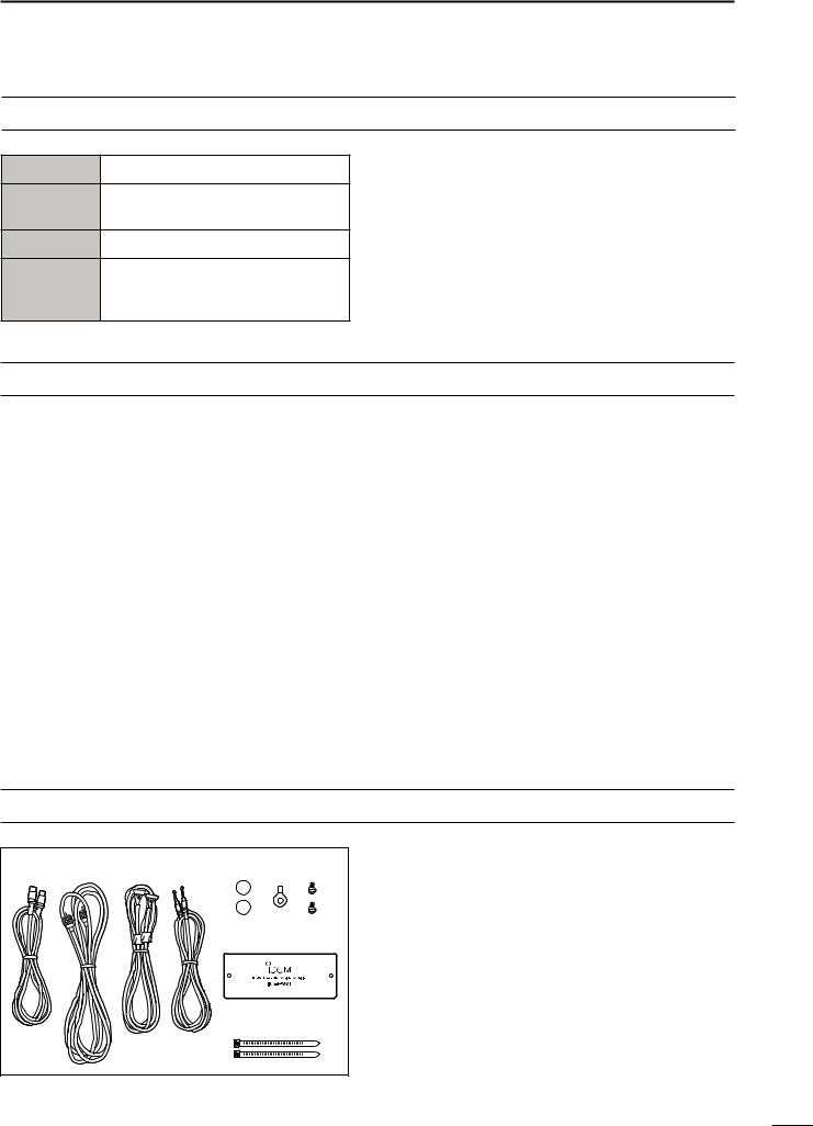
SUPPLIED ACCESSORIES
q w e r t y u
i
o
Accessories included with the IC-PW1/EURO: Qty.
q Accessory cable (OPC-104B) .............................. |
1 |
w Coaxial cable (OPC-125B) .................................. |
1 |
e Separation cable (OPC-730) ............................... |
1 |
r Remote control (CI-V) cable (OPC-718) .............. |
1 |
t Remote controller feet ......................................... |
2 |
y Grounding lug ...................................................... |
1 |
u Dummy panel screws .......................................... |
2 |
i Dummy panel ...................................................... |
1 |
o Cable ties ............................................................. |
2 |
ii
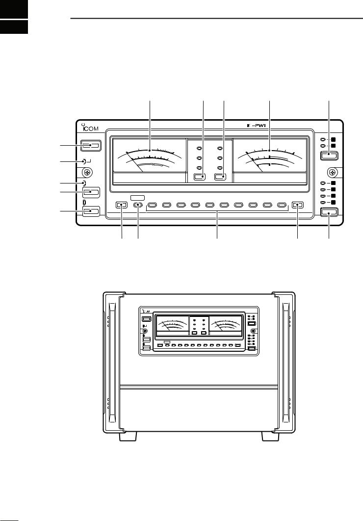
1 PANEL DESCRIPTION
■ Front panel and remote controller
q
w
e r
t
!5 |
!4 |
!3 |
!2 |
!1 |
|
HF/50MHz ALL BAND 1kW LINEAR AMPLIFIER |
|
|
|
POWER |
|
|
|
1 |
|
|
|
|
|
|
|
|
100 |
|
250 |
500 |
1K |
|
Po |
VD |
|
|
20 |
30 |
40 |
|
|
2 |
|
|
|
0 |
|
1.5K |
|
|
10 |
|
50 |
|
|||||||||
|
|
|
|
30 |
|
|
|
ID |
SWR |
0 |
|
|
|
|
60 |
|
|
||
TRANSMIT |
Po |
0 |
10 |
20 |
40 |
50 |
60 |
W |
1 |
1.5 |
2 |
3 |
|
|
V |
INPUT |
|||
|
|
|
|
|
|
VD |
|
|
|
|
∞ |
||||||||
|
|
ID |
|
|
|
|
HOT |
|
A |
TEMP |
ALC |
SWR |
|
ALC adj |
|
|
|
||
|
|
TEMP |
|
|
|
|
|
ALC |
|
|
|
|
|
|
|||||
|
|
|
|
|
|
|
|
|
|
|
|
|
|
|
|
||||
|
METER-1 |
|
|
|
|
|
|
|
METER-2 |
|
|
|
|
TUNER |
|
|
|
|
|
|
|
|
|
|
|
1 |
|
|
|
|
|
|
|
|
|
|
|
|
|
2 |
|
AMP/ |
DOWN AUTO 1.8 |
3.5 |
7 |
10 |
14 |
18 |
21 |
24 |
28 |
50 |
UP |
3 |
|
4 |
|||||||||||||
|
|
|
|
|
|
|
|
|
|
|
|||
PROTECT |
|
|
|
|
|
|
|
|
|
|
|
ANT |
y u |
i |
o |
!0 |
HF/50MHz ALL BAND 1kW LINEAR AMPLIFIER 


POWER |
|
|
|
|
|
|
|
|
|
|
|
|
|
|
|
|
|
|
|
|
1 |
|
|
|
100 |
250 |
500 |
|
1K |
|
Po |
|
VD |
|
|
|
20 |
30 |
40 |
|
|
|
2 |
|
0 |
|
|
1.5K |
|
|
|
|
10 |
|
50 |
60 |
|
||||||||
|
|
|
|
|
|
|
ID |
|
SWR |
|
0 |
|
|
|
|
|
|
|
|||
TRANSMIT |
Po |
0 |
10 20 |
30 |
40 |
50 |
60 |
W |
|
VD |
1 |
1.5 |
2 |
3 |
|
|
∞ |
V |
INPUT |
||
|
ID |
|
|
|
HOT |
A |
TEMP |
|
ALC |
|
SWR |
|
|
ALC adj |
|
|
|
|
|||
|
|
|
|
|
|
|
|
|
|
|
|
|
|||||||||
|
|
TEMP |
|
|
|
|
|
|
|
|
|
ALC |
|
|
|
|
|
|
|
||
|
|
|
METER-1 |
|
|
|
|
|
|
|
|
|
METER-2 |
|
|
|
|
||||
TUNER |
|
|
|
|
|
|
|
|
|
|
|
|
|
|
|
|
|
|
|
|
1 |
|
|
|
|
|
|
|
|
|
|
|
|
|
|
|
|
|
|
|
|
|
2 |
AMP/ |
DOWN |
AUTO |
1.8 |
|
3.5 |
7 |
10 |
14 |
18 |
21 |
24 |
|
|
28 |
50 |
|
UP |
|
3 |
||
|
|
|
|
|
4 |
||||||||||||||||
PROTECT |
|
|
|
|
|
|
|
|
|
|
|
|
|
|
|
|
|
|
|
|
|
ANT
1

q POWER SWITCH [POWER] (p. 12) Push momentarily to turn power ON.
w TRANSMIT INDICATOR [TRANSMIT] (p. 16)
Lights green while transmitting.
During transmission, a humming may sound depending on the output power. This is caused by the large current produced by the power supply and does not indicate equipment malfunction.
e ANTENNA TUNER INDICATOR [TUNER] (p. 16)
•Lights while the antenna tuner is activated.
•Blinks while tuning and the SWR becomes 1.5:1 or greater on the 50 MHz band.
•Goes out after slow blinking when antenna turner cannot tune the selected antenna (SWR 1.5:1 or greater).
r ANTENNA TUNER SWITCH [TUNER] (p. 17)
•Turns the antenna tuner ON and OFF (bypass) when pushed momentarily.
-The [TUNER] indicator lights while the antenna tuner is activated; blinks while tuning.
-While operating in the 50 MHz band, the antenna tuner does not start automatically. Push [TUNER] for 2 sec. to tune the antenna manually.
•Starts to tune the antenna manually when pushed for 2 sec.
-When the tuner cannot tune the antenna (SWR 1.5:1 or greater), the tuning circuit is bypassed automatically after 20 sec.
t LINEAR AMPLIFIER SWITCH [AMP/PROTECT]
Turns the linear amplifier ON and OFF.
-The [AMP/PROTECT] indicator lights green when the linear amplifier is ON. (p. 16)
-The [AMP/PROTECT] indicator lights red when the protector circuit is activated. (p. 17)
-When the linear amplifier is OFF, the [AMP/PROTECT] does not light and the exciter’s signal is applied to one of the output connectors or the IC-PW1/EURO’s antenna tuner.
y LOWER BAND SELECTOR [DOWN] (p. 16) Selects the lower operating band when pushed.
PANEL DESCRIPTION 1
u AUTOMATIC INDICATOR [AUTO] (p. 16) Indicates that automatic band selection is activated. (When an Icom CI-V transceiver is connected.)
i BAND INDICATORS (p. 16)
Indicate the selected operating band.
o UPPER BAND SELECTOR [UP] (p. 16) Selects the higher operating band when pushed.
!0OUTPUT ANTENNA SELECTOR [ANT] (p. 16) Selects one of 4 output antenna connectors.
!1INPUT ANTENNA SELECTOR [INPUT] (p. 16) Selects one of 2 input antenna connectors.
!2TRANSMIT METER-2 [METER-2]
Shows the final FET’s voltage (VD), SWR (Standing Wave Ratio) or ALC (Automatic Level Control) level.
!3TRANSMIT METER-2 SELECTOR
Selects the final FET’s voltage (VD), SWR (Standing Wave Ratio) or ALC (Automatic Level Control) level for transmit meter-2.
!4TRANSMIT METER-1 SELECTOR
Selects the RF output power (PO), final FET’s current (ID) or heatsink temperature (TEMP) for transmit meter-1.
!5TRANSMIT METER-1 [METER-1]
Shows the RF output power (PO), final FET’s current (ID) or heatsink temperature (TEMP).
2

1 PANEL DESCRIPTION
■ Rear panel
q |
|
|
|
|
|
|
ANT4 |
|
ANT3 |
ANT2 |
ANT1 |
|
|
w |
|
|
|
|
|
|
ACC-2 |
ALC2 SEND2 |
ACC-1 |
ALC1 SEND1 |
|
|
|
|
|
|
|
|
EXCITER |
|
|
|
|
|
|
1 |
1&2 |
CONTROLLER |
REMOTE |
ALC adj2 |
REMOTE |
ALC adj1 |
|
|
e |
|
|
||||
|
|
|
|
|
|
|
r |
|
|
|
|
|
|
t |
|
|
|
|
|
|
y |
|
|
|
|
|
|
u |
|
|
|
|
L |
|
|
|
|
|
|
|
|
i |
|
|
|
|
|
|
|
|
|
|
|
N |
|
INPUT1 |
INPUT2 |
!1
!0
o
q OUTPUT ANTENNA CONNECTORS [ANT1] – [ANT4] (p. 6)
Accept a 50 Ω antenna with a PL-259 connector.
w ACCESSORY SOCKET-1 [ACC-1] ACCESSORY SOCKET-2 [ACC-2]
Enable connection to Icom exciters (transceivers).
-See the page at right for socket information.
-The [ACC-2] socket is connected in parallel with [ACC- 1] by default and can be used for connecting external equipment such as the EX-627 AUTOMATIC ANTENNA
SELECTOR, etc. These sockets can be separated by the [EXCITER] switch. (!0)
e REMOTE CONTROLLER CABLE HOLE [CONTROLLER] (p. 11)
Used for separation of the remote controller and linear amplifier.
r ALC OUTPUT JACKS [ALC1]/[ALC2] (p. 12) Connect to the ALC input jack of a non-Icom exciter (transceiver).
- Control voltage: –10 to 0 V DC
t SEND CONTROL JACKS [SEND1]/[SEND2]
(p. 9)
Input terminals for transmit control. Go to ground while transmitting.
-Max. control level: 5.0 V DC/0.1 A
-Ground level: –0.5 to 0.8 V DC
y CI-V REMOTE CONTROL JACKS [REMOTE]
(pgs. 7–9)
Used for band control with an Icom CI-V exciter (transceiver).
u ALC LEVEL ADJUSTMENT POTS [ALC adj1]/[ALC adj2] (p. 12) Adjust the ALC levels.
RCAUTION! DO NOT operate the ICPW1/EURO before adjusting the [ALC adj1] and [ALC adj2] pots properly. This may damage the final FETs.
i CIRCUIT BREAKERS (p. 17)
Cut off the AC input when over current occurs.
- Circuit breaker capacity: 20 A (U.S.A. version) 15 A (Europe version)
o GROUND TERMINAL (p. 6)
Connect this terminal to a ground to prevent electrical shocks, TVI, BCI and other problems.
3

PANEL DESCRIPTION 1
!0EXCITER SELECTOR [EXCITER] (pgs. 7–9)
Sets the connected exciter number.
-Select [1] when 1 exciter is connected. [ACC-2] outputs the received [ACC-1] signal to another Icom option
such as the EX-627 AUTOMATIC ANTENNA SELECTOR.
-Select [1&2] when 2 exciters or 1 exciter with 2 specified band antenna connectors is connected.
!1INPUT ANTENNA CONNECTORS [INPUT1]/[INPUT2] (p. 6)
Accept a 50 Ω antenna with a PL-259 connector.
DACC-1 SOCKET
ACC-1 |
PIN NO. |
PIN NAME |
DESCRIPTION |
SPECIFICATIONS |
|||
|
|
|
1 |
8 V |
Regulated reference 8 V DC input |
Input voltage |
: 8 V ±0.3 V |
|
|
|
for band control. |
Input current |
: Less than 10 mA |
||
|
|
|
|
|
|||
|
|
|
|
|
|
|
|
|
|
|
2 |
GND |
Connects to ground. |
|
|
|
|
|
|
|
|
|
|
|
|
|
|
|
Input/output pin. |
Ground level |
: –0.5 V to 0.8 V |
7 |
|
6 |
3 |
SEND |
Goes to ground when transmitting. |
Output current |
: Less than 20 mA |
3 |
|
1 |
|
|
When grounded, transmits. |
Input current |
: Less than 200 mA |
5 |
2 |
4 |
|
|
|
|
|
|
|
Band voltage input. |
|
|
|||
|
|
|
|
|
|
||
|
|
|
4 |
BAND |
Input voltage |
: 0 to 8.0 V |
|
|
|
|
(Varies with amateur band) |
||||
Rear panel |
|
|
|
|
|||
|
|
|
|
|
|||
|
|
|
Control voltage |
: –10 to 0 V |
|||
view |
5 |
ALC |
ALC voltage output. |
||||
|
|
|
Output impedance : 10 kΩ |
||||
|
|
|
|
|
|
||
|
|
|
|
|
|
|
|
|
|
|
6 |
NC |
No connection. |
|
|
|
|
|
|
|
|
|
|
|
|
|
7 |
13.8 V |
13.8 V DC input terminal. |
Input current |
: Less than 1 A |
|
|
|
|
|
|
|
|
DACC-2 SOCKET (w/[EXCITER] is “1”)
The following descriptions are applied when the [EXCITER] switch is set to “1” (default). When [EXCITER] is set to “1&2,” [ACC-2] functions the same as [ACC-1] above for the 2nd exciter.
ACC-2 |
PIN NO. |
PIN NAME |
DESCRIPTION |
SPECIFICATIONS |
||||
|
|
|
1 |
8 V |
Regulated reference 8 V DC output |
Output voltage |
: 8 V ±0.3 V |
|
|
|
|
from the [ACC-1] socket. |
Output current |
: Less than 10 mA |
|||
|
|
|
|
|
||||
|
|
|
|
|
|
|
|
|
|
|
|
2 |
GND |
Connects to ground. |
|
||
|
|
|
|
|
|
|
|
|
|
|
|
|
|
Input/output pin. |
Ground level |
: –0.5 V to 0.8 V |
|
|
|
|
3 |
SEND |
Goes to ground when transmitting. |
Output current |
: Less than 20 mA |
|
7 |
|
6 |
|
|
When grounded, transmits. |
Input current |
: Less than 200 mA |
|
3 |
|
1 |
|
|
|
|
|
|
|
|
|
Band voltage output from the |
|
|
|||
5 |
2 |
4 |
|
|
|
|
||
4 |
BAND |
[ACC-1] socket. |
Output voltage |
: 0 to 8.0 V |
||||
|
|
|||||||
|
|
|
||||||
Rear panel |
|
|
(Varies with amateur band) |
|
|
|||
|
|
|
|
|
||||
|
|
|
Control voltage |
: –10 to 0 V |
||||
view |
5 |
ALC |
ALC voltage output. |
|||||
|
|
|
Output impedance : 10 kΩ |
|||||
|
|
|
|
|
|
|||
|
|
|
|
|
|
|
|
|
|
|
|
6 |
NC |
No connection. |
|
||
|
|
|
|
|
|
|
|
|
|
|
|
7 |
13.8 V |
13.8 V DC output terminal from the |
Output current |
: Less than 1 A |
|
|
|
|
[ACC-1] socket. |
|||||
|
|
|
|
|
|
|
||
|
|
|
|
|
|
|
|
|
4

2 INSTALLATION AND CONNECTIONS
■Unpacking
After unpacking, immediately report any damage to the delivering carrier or dealer. Keep the shipping cartons.
For a description and a diagram of accessory equipment included with the IC-PW1/EURO, see SUPPLIED ACCESSORIES on p. ii of this manual.
■Ferrite core installation
The supplied cable ties (o in SUPPLIED ACCESSORIES) should be attached to the AC cable of the IC-PW1/EURO as illustrated below.
Attach and position the cable ties to the AC cable  as illustrated.
Ferrite core
Cut the cable ties so that enough
AC cable length remains to secure the ferrite
core in place.
■AC power cable connection
A suitable AC power plug must be connected to the AC power cable end. See the diagram below for connection procedures. AC input voltage is automatically selected.
The IC-PW1/EURO can accept either 100–120 V AC or 200–240 V AC power.* However, we recommend using 200–240 V AC rather than 100–120 V AC for better power supply efficiency and longer periods of transmission.
* Europe version: 230 V AC only
DSingle-phase 3-wire line (200–240 V AC)
qThe green wire from the AC power cable must be connected to the protective earth.
wThe black and white wires from the AC power cable can be connected to either terminal.
 *Use the appropriate AC plug if required.
*
white black green
NOTE: Only one ferrite core is attached with the ICPW1EURO.
■OPC-853 AC cable with line filter
The IC-PW1EURO must be used with the OPC-853 AC cable to satisfy European R&TTE requirements.
■Selecting a location
Select a location for the linear amplifier that allows adequate air circulation, free from extreme heat, cold, or vibrations, and away from TV sets, TV antenna elements, radios and other electro-magnetic sources.
The linear amplifier and remote controller sections of the IC-PW1/EURO can be separated. The remote controller can be placed near the operator for easy monitoring of linear amplifier conditions at any time. See p. 10 for separation instructions.
The linear amplifier must be placed on a solid foundation since it is very heavy.
DSingle-phase 2-wire line (100–120 V AC)
qThe green wire from the AC power cable must be connected to the protective earth.
wThe black wire from the AC power cable must be connected to the hot (live) wire.
eThe white wire from the AC power cable must be connected to the return wire.
white black green
GND
DThree-phase 3-wire line (200–240 V AC)
qThe green wire from the AC power cable must be connected to the protective earth.
wThe black and white wires from the AC power cable can be connected to 2 of 3 wires.
white black green
5
 Loading...