


Icom IC-F6128D, IC-F5121D, IC-F6121D, IC-F5123D, IC-F6123D User Manual
...INSTRUCTION MANUAL
VHF MOBILE TRANSCEIVERS
iF5120D
Series
UHF MOBILE TRANSCEIVERS
iF6120D
Series

IMPORTANT
READ ALL INSTRUCTIONS carefully and com-
pletely before using the transceiver.
SAVE THIS INSTRUCTION MANUAL — This
instruction manual contains important operating instructions for the IC-F5121D, IC-F5123D, IC-F5128D VHF MOBILE TRANSCEIVERS and the IC-F6121D, IC-F6123D, ICF6128D UHF MOBILE TRANSCEIVERS.
EXPLICIT DEFINITIONS
WORD |
DEFINITION |
|
RWARNING! |
Personal injury, fire hazard or electric |
|
shock may occur. |
||
CAUTION |
Equipment damage may occur. |
|
NOTE |
If disregarded, inconvenience only. No risk |
|
of personal injury, fire or electric shock. |
||
|
i
FCC INFORMATION
This equipment has been tested and found to comply with the limits for a Class A digital device, pursuant to part 15 of the FCC Rules. These limits are designed to provide reasonable protection against harmful interference when the equipment is operated in a commercial environment. This equipment generates, uses, and can radiate radio frequency energy and, if not installed and used in accordance with the instruction manual, may cause harmful interference to radio communications. Operation of this equipment in a residential area is likely to cause harmful interference in which case the user will be required to correct the interference at his own expense.
CAUTION: Changes or modifications to this transceiver, not expressly approved by Icom Inc., could void your authority to operate this transceiver under FCC regulations.
Icom is not responsible for the destruction or damage to the Icom transceiver, if the malfunction is because of:
•Force majeure, including, but not limited to, fires,earthquakes, storms, floods, lightnings, or other naturaldisasters, disturbances, riots, war, or radioactivecontamination.
•The use of Icom transceiver with any equipment that is not manufactured or approved by Icom.

PRECAUTIONS
R WARNING! NEVER operate the transceiver during a lightning storm. It may result in an electric shock, cause a fire or damage the transceiver. Always disconnect the power source and antenna before a storm.
R WARNING! NEVER connect the transceiver to an AC outlet. This may pose a fire hazard or result in an electric shock.
R WARNING! NEVER connect the transceiver to a power source of more than 16 V DC or use reverse polarity. This could cause a fire or damage the transceiver.
R WARNING! NEVER cut the DC power cable between the DC plug and fuse holder. If an incorrect connection is made after cutting, the transceiver might be damaged.
R WARNING! NEVER place the transceiver where normal operation of the vehicle may be hindered or where it could cause bodily injury.
CAUTION: NEVER allow children to touch the transceiver.
CAUTION: NEVER expose the transceiver to rain, snow or any liquids.
DO NOT use or place the transceiver in areas with temperatures below –30°C (–22°F) or above +60°C (+140°F), or in areas subject to direct sunlight, such as the dashboard.
DO NOT operate the transceiver without running the vehicle’s engine. The vehicle’s battery will quickly run out when the transceiver transmits while the vehicle’s engine is OFF.
DO NOT place the transceiver in excessively dusty environments.
DO NOT place the transceiver against walls. This will obstruct heat dissipation.
DO NOT use harsh solvents such as benzine or alcohol when cleaning, as they will damage the transceiver surfaces.
BE CAREFUL! The transceiver will become hot when operating continuously for long periods of time.
USE the specified microphone only. Other microphones have different pin assignments and may damage the transceiver.
Icom, Icom Inc. and the Icom logo are registered trademarks of Icom Incorporated (Japan) in Japan, the United States, the United Kingdom, Germany, France, Spain, Russia, Australia, New Zealand, and/ or other countries.
All other products or brands are registered trademarks or trademarks of their respective holders.
ii

TABLE OF CONTENTS
IMPORTANT........................................................................... |
i |
|
EXPLICIT DEFINITIONS....................................................... |
i |
|
FCC INFORMATION.............................................................. |
i |
|
PRECAUTIONS.................................................................... |
ii |
|
1 |
PANEL DESCRIPTION................................................ |
1–7 |
|
■ Front panel.................................................................... |
1 |
|
■ Function display............................................................ |
2 |
|
■ Programmable function keys......................................... |
3 |
2 |
BASIC OPERATION.................................................. |
8–14 |
|
■ Turning ON the power................................................... |
8 |
|
■ Channel selection......................................................... |
8 |
|
■ Call procedure.............................................................. |
9 |
|
■ Receiving and transmitting............................................ |
9 |
|
■ User Set mode............................................................ |
12 |
|
■ Encryption function..................................................... |
12 |
|
■ Stun function............................................................... |
12 |
|
■ Emergency transmission............................................. |
13 |
|
■ Power OFF Emergency function........................................ |
14 |
|
■ Priority A channel selection........................................ |
14 |
3 |
CONNECTION AND MAINTENANCE..................... |
15–17 |
|
■ Rear panel connection................................................ |
15 |
|
■ Supplied Accessories................................................. |
16 |
|
■ Mounting the transceiver............................................. |
16 |
|
■ Antenna...................................................................... |
17 |
|
■ Fuse replacement....................................................... |
17 |
|
■ Cleaning...................................................................... |
17 |
|
■ Options....................................................................... |
17 |
4 |
SAFETY TRAINING INFORMATION....................... |
18–21 |
iii

|
|
1 |
|
|
PANEL DESCRIPTION |
|
|
||
|
|
|||
|
|
|||
■ Front panel |
|
|
||
1 |
||||
q |
Function display (p. 2) |
w |
e Speaker |
t
q AF VOLUME CONTROL KNOB [VOL]
Rotate the knob to adjust the audio output level.
• Minimum audio level is pre-programmed. (p. 12)
w UP/DOWN KEYS [CH Up]/[CH Down]
Push to select an operating channel, etc.
* The desired function can be assigned by your dealer. (p. 3)
e POWER KEY [ ]
]
Push to turn the power ON or OFF.
•The following optional functions are available at power ON:
-Automatic scan start
-Password prompt
r DEALER-PROGRAMMABLE KEYS
Required functions can be independently programmed by your dealer. (p. 3)
 r
r
t MICROPHONE CONNECTOR
Connect the supplied or optional microphone.
 NEVER connect non-specified microphones. The pin assign-
  ments may be different and may damage the transceiver.
D Microphone
The supplied or optional microphone has a PTT switch and a hanger hook.
•The following functions are available when the microphone is ON or OFF hook (depending on the preprogramming):
-Automatic scan starts when you put it ON hook.
-Scan is cancelled when you take it OFF hook.
-Scan is paused when you take it OFF hook.
-Automatically selects the Priority channel when you take it OFF hook.
-Sets to the ‘Inaudible’ mode (mute state) when you put it ON hook.
-Sets to the ‘Audible’ mode (unmute state) when you take it OFF hook.
1
1 PANEL DESCRIPTION
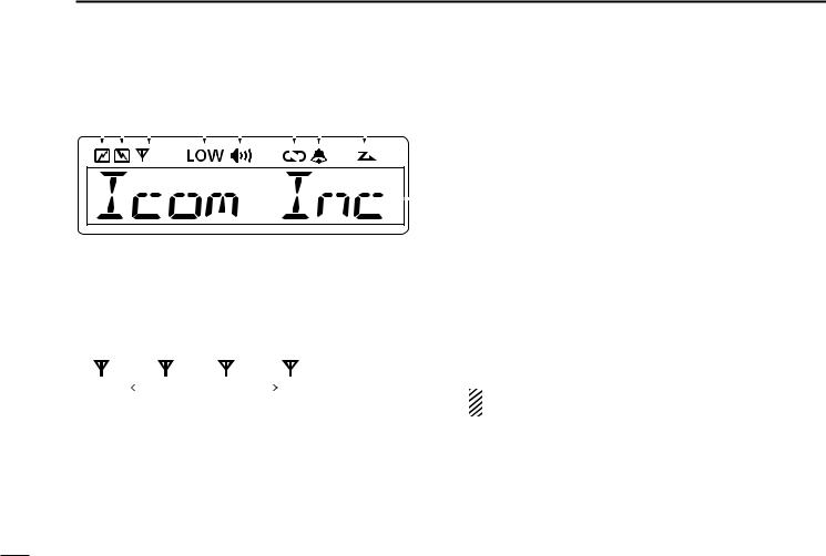
■ Function display
q w e |
r t |
|
y u |
i |
y ENCRYPTION ICON |
|||||||||||||||||||
|
Appears when the encryption function is activated while |
|||||||||||||||||||||||
|
|
|
|
|
|
|
|
|
|
|
|
|
|
|
|
|
|
|
|
|
|
|
||
|
|
|
|
|
|
|
|
|
|
|
|
|
|
|
|
|
|
|
|
|
|
|
operating in the digital mode. |
|
|
|
|
|
|
|
|
|
|
|
|
|
|
|
|
|
|
|
|
|
|
|
|
u BELL ICON |
|
|
|
|
|
|
|
|
|
|
|
|
|
|
|
|
|
|
|
|
|
|
|
|
||
|
|
|
|
|
|
|
|
|
|
|
|
|
|
|
|
|
|
|
|
|
|
|
Appears/blinks when a matching 2/5-tone or Digital ID* is |
|
|
|
|
|
|
|
|
|
|
|
|
|
|
|
|
|
|
|
|
|
|
|
o |
received, depending on the preprogramming. |
|
|
|
|
|
|
|
|
|
|
|
|
|
|
|
|
|
|
|
|
|
|
|
|||
|
|
|
|
|
|
|
|
|
|
|
|
|
|
|
|
|
|
|
|
|
|
|
i SCAN ICON |
|
|
|
|
|
|
|
|
|
|
|
|
|
|
|
|
|
|
|
|
|
|
|
|
Blinks during a scan. |
|
q TRANSMIT ICON |
|
|
|
|
|
|
|
|
|
|
|
Appears when a scan channel is selected. |
||||||||||||
|
|
|
|
|
|
|
|
|
|
|
o ALPHANUMERIC DISPLAY |
|||||||||||||
Appears while transmitting a signal. |
|
|
|
|
||||||||||||||||||||
w BUSY ICON |
|
|
|
|
|
|
|
|
|
|
|
|
|
|
|
Displays an operating channel number, channel name, |
||||||||
|
|
|
|
|
|
|
|
|
|
|
|
|
|
|
User Set mode contents, DTMF code, etc. |
|||||||||
Appears while the channel is busy (receiving). |
||||||||||||||||||||||||
|
||||||||||||||||||||||||
e SIGNAL STRENGTH ICON |
|
|
|
|
|
|
|
|
|
|
|
* Digital operation only |
||||||||||||
Shows the relative receive signal strength level. |
||||||||||||||||||||||||
|
||||||||||||||||||||||||
|
|
|
|
|
|
|
|
|
|
|
|
|
|
|
|
|
|
|
|
|
|
|
||
|
|
|
|
|
|
|
|
|
|
|
|
|
|
|
|
|
|
|
|
|
|
|
|
|
|
|
|
|
|
|
|
|
|
|
|
|
|
|
|
|
|
|
|
|
|
|
|
|
|
Weak |
|
|
Receive Signal level |
|
Strong |
|
|
|
|
See the operating guide for details of MDC and Digital |
||||||||||||||
|
|
|
|
|
|
|||||||||||||||||||
|
|
|
|
|
|
|||||||||||||||||||
|
|
|
|
|
|
|
|
|
|
|
|
|
|
|
|
|
|
|
|
|
|
|
||
r LOW POWER ICON |
|
|
|
|
|
|
|
|
|
|
|
system operations. Ask your dealer for details. |
||||||||||||
Appears when low output power is selected. |
|
|
|
|
|
|||||||||||||||||||
t AUDIBLE ICON
Appears when the channel is in the ‘Audible’ (unmute) mode.
Appears when a matching signal is received.
2

■ Programmable function keys
The following functions can be assigned to [UP], [DOWN], [P0], [P1], [P2] and [P3] programmable function keys. Consult your Icom dealer or system operator for details concerning your transceivers programming.
CH UP AND DOWN KEYS
As described in the following topics, after pushing a programmed key, push [CH Up] or [CH Down] to select an option, setting, etc.
ZONE KEY
Push this key, then select the desired zone using [CH Up]/ [CH Down].
 What is “zone”?— Certain channels are grouped together
 and assigned to a zone, according to their intended to use.
For example, ‘Staff A’ and ‘Staff B’ are assigned to a “Busi-
 ness” zone, and ‘John’ and ‘Cindy’ are assigned to a “Pri-
  vate” zone.
PANEL DESCRIPTION 1
1
SCAN START/STOPKEY
Push to start and cancel scanning operation.
•When a scan is started with the Power ON Scan or Automatic scan function, push this key to cancel it. The cancelled scan resumes after the pre-programmed time period.
Hold down this key for 1 second to display the scan group, then push [CH Up] or [CH Down] to select the desired one.
SCAN ADD/DEL (TAG) KEY
Push to add the channel to, or delete it from, the current scan group.
1.Push to display the scan group, then push [CH Up] or [CH Down] to select the desired one.
2.Push to add the channel to, or delete it from, the selected scan group.
3.Hold down for 1 second to exit the scan list selection mode.
While a scan is paused on a non-priority channel, push this key to delete the selected channel from the scan group.
 Depending on the setting, the cleared channel is added
  to the scan group again after the scan is cancelled.
3

1 PANEL DESCRIPTION
Programmable function keys (Continued)
PRIO A/B KEYS
Push to select the Priority A or Priority B channel.
Hold down [Prio A (Rewrite)] or [Prio B (Rewrite)] for 1 second to rewrite the operating channel as Priority A or Priority B,
MR-CH 1/2/3/4 KEYS
Push to directly select memory channel 1 to 4.
MONI (AUDI) KEY
Push to turn the CTCSS (DTCS) or 2/5-tone squelch mute ON or OFF.
•Only during LMR (Land Mobile Radio) operation, push to open any squelch, or deactivate any mute functions.
•Only during PMR (Private Mobile Radio) operation, push to activate one or two of the following functions on each channel (depending on the preprogramming):
-Hold down to unmute the channel (‘Audible’ mode).
-Push to mute the channel (‘Inaudible’ mode).
-After the communication is finished, push to send a ‘reset code’ (only 5-tone operation).
 NOTE: The ‘Audible’ (unmute) mode may automatically return to the ‘Inaudible’ (mute) mode, after the pre-pro-
 grammed time period.
LIGHT KEY
Push to turn ON the backlight for about 5 seconds, when the backlight function is set to “OFF” in the User Set mode.
LOCK KEY
Hold down this key until “LOCK ON” is displayed to electronically lock all programmable keys except the following:
[Moni(Audi)], [Lock], [Call] (incl. Call A and Call B), [Emergency], [Surveillance], [Siren], [Lone Worker] and [Light].
When the Key Lock function is ON, hold down this key until “LOCK OFF” is displayed to turn it OFF.
LONE WORKER KEY
Push to turn the Lone Worker function ON or OFF.
•If the Lone Worker function is turned ON, and no operation occurs during the pre-programmed time period, the Emergency function is automatically turned ON.
HIGH/LOW KEY
Push to select the transmit output power temporarily or permanently, depending on the preprogramming.
• Ask your dealer for the output power level for each selection.
C.TONE CH ENT KEY
Push to enter the continuous tone channel selection mode. Then, push [CH Up] or [CH Down] to change the tone frequency/code setting. The selected channel remains set as the continuous tone channel until another channel is designated as such.
4

TONE/RAN CH SELECT KEY
While in analog mode, push to enter the continuous tone channel selection mode. Then push [CH Up] or [CH Down] to select a desired tone frequency/code setting. After the selection, push this key again to set it.
While in digital mode, push to enter the RAN channel selection mode. Then push [CH Up] or [CH Down] to select a desired RAN code. After the selection, push this key again to set it.
While in mixed (digital and analog) mode, push to enter the continuous tone channel selection mode. Then push [CH Up] or [CH Down] to select a desired tone frequency/ code setting. After setting, push this key to set it. After that, the RAN channel selection mode appears. Select a desired RAN code with [CH Up] or [CH Down]. After the selection, push this key again to set it.
TALK AROUND KEY
Push to turn the Talk Around function ON or OFF.
•The Talk Around function equalizes the transmit frequency to the receive frequency for transceiver-to-transceiver communication.
PANEL DESCRIPTION 1
1
WIDE/NARROW KEY
Push to toggle the IF bandwidth between wide and narrow.
•The wide passband width can be selected from 25.0 or 20.0 kHz using the CS-F3100D/F5120D cloning software. (PMR operation only) Ask your dealer for details.
DTMF AUTODIAL KEY
Push to enter the DTMF channel selection mode, then push [CH Up] or [CH Down] to select the desired DTMF channel.
After selecting the DTMF channel, push again to transmit the selected DTMF code.
RE-DIAL KEY
Push to transmit the last-transmitted DTMF code.
• TX memories are cleared after turning OFF the transceiver.
EMERGENCY KEY
Hold down for a specified period to transmit an emergency call.
•If you want to cancel the emergency call, hold down the key again, before transmitting it.
5
 Loading...