


 Loading...
SERVICE MANUAL
VHF FM TRANSCEIVER

INTRODUCTION |
|
DANGER |
|
|
|
This service manual describes the latest service information for the IC-V8000 VHF FM TRANSCEIVER at the time of publication.
VERSION |
SYMBOL |
SUPPLIED MICROPHONE |
|
Asia |
SEA |
HM-118N |
|
|
|
|
|
C.S.America |
CSA |
HM-118TN |
|
|
|
||
CSA-1 |
HM-133V |
||
|
|||
|
|
||
U.S.A. |
USA-2 |
||
|
|||
|
|
||
USA-3 |
HM-118TAN |
||
|
|||
|
|
|
To upgrade quality, any electrical or mechanical parts and internal circuits are subject to change without notice or obligation.
NEVER connect the transceiver to an AC outlet or to a DC power supply that uses more than 16 V. This will ruin the transceiver.
DO NOT expose the transceiver to rain, snow or any liquids.
DO NOT reverse the polarities of the power supply when connecting the transceiver.
DO NOT apply an RF signal of more than 20 dBm (100mW) to the antenna connector. This could damage the transceiver's front end.
ORDERING PARTS
Be sure to include the following four points when ordering replacement parts:
1.10-digit order numbers
2.Component part number and name
3.Equipment model name and unit name
4.Quantity required
<SAMPLE ORDER>
1110003200 S.IC TA31136FN |
IC-V8000 |
MAIN UNIT |
5 pieces |
8810006050 Screw Icom screw E7 |
IC-V8000 |
Chassis |
10 pieces |
Addresses are provided on the inside back cover for your convenience.
REPAIR NOTES
1.Make sure a problem is internal before disassembling the transceiver.
2.DO NOT open the transceiver until the transceiver is disconnected from its power source.
3.DO NOT force any of the variable components. Turn them slowly and smoothly.
4.DO NOT short any circuits or electronic parts. An insulated turning tool MUST be used for all adjustments.
5.DO NOT keep power ON for a long time when the transceiver is defective.
6.DO NOT transmit power into a signal generator or a sweep generator.
7.ALWAYS connect a 50 dB to 60 dB attenuator between the transceiver and a deviation meter or spectrum analyzer when using such test equipment.
8.READ the instructions of test equipment thoroughly before connecting equipment to the transceiver.

TABLE OF CONTENTS
SECTION |
1 |
SPECIFICATIONS |
|
SECTION |
2 |
INSIDE VIEWS |
|
SECTION |
3 |
DISASSEMBLY AND OPTION INSTRUCTIONS |
|
SECTION |
4 |
CIRCUIT DESCRIPTION |
|
|
4-1 |
RECEIVER CIRCUITS . . . . . . . . . . . . . . . . . . . . . . . . . . . . . . . . . . . . . . . . . . . . . . . . . . . . . |
4-1 |
|
4-2 |
TRANSMITTER CIRCUITS . . . . . . . . . . . . . . . . . . . . . . . . . . . . . . . . . . . . . . . . . . . . . . . . . . |
4-2 |
|
4-3 |
PLL CIRCUITS . . . . . . . . . . . . . . . . . . . . . . . . . . . . . . . . . . . . . . . . . . . . . . . . . . . . . . . . . . . |
4-3 |
|
4-4 |
POWER SUPPLY CIRCUITS . . . . . . . . . . . . . . . . . . . . . . . . . . . . . . . . . . . . . . . . . . . . . . . . |
4-3 |
|
4-5 |
PORT ALLOCATIONS . . . . . . . . . . . . . . . . . . . . . . . . . . . . . . . . . . . . . . . . . . . . . . . . . . . . . |
4-4 |
SECTION |
5 |
PARTS LIST |
|
SECTION |
6 |
MECHANICAL PARTS AND DISASSEMBLY |
|
|
6-1 |
IC-V8000 . . . . . . . . . . . . . . . . . . . . . . . . . . . . . . . . . . . . . . . . . . . . . . . . . . . . . . . . . . . . . . . |
6-1 |
|
6-2 |
HM-133V . . . . . . . . . . . . . . . . . . . . . . . . . . . . . . . . . . . . . . . . . . . . . . . . . . . . . . . . . . . . . . . |
6-3 |
SECTION |
7 |
SEMI-CONDUCTOR INFORMATION |
|
SECTION |
8 |
BOARD LAYOUTS |
|
|
8-1 |
HM-133V . . . . . . . . . . . . . . . . . . . . . . . . . . . . . . . . . . . . . . . . . . . . . . . . . . . . . . . . . . . . . . . |
8-1 |
|
8-2 |
LOGIC BOARD . . . . . . . . . . . . . . . . . . . . . . . . . . . . . . . . . . . . . . . . . . . . . . . . . . . . . . . . . . . |
8-2 |
|
8-3 |
MAIN UNIT . . . . . . . . . . . . . . . . . . . . . . . . . . . . . . . . . . . . . . . . . . . . . . . . . . . . . . . . . . . . . . |
8-4 |
SECTION 9 BLOCK DIAGRAM
SECTION 10 VOLTAGE DIAGRAM
10-1 MAIN UNIT . . . . . . . . . . . . . . . . . . . . . . . . . . . . . . . . . . . . . . . . . . . . . . . . . . . . . . . . . . . . . .10-1 10-2 LOGIC BOARD . . . . . . . . . . . . . . . . . . . . . . . . . . . . . . . . . . . . . . . . . . . . . . . . . . . . . . . . . . .10-2 10-3 HM-133V . . . . . . . . . . . . . . . . . . . . . . . . . . . . . . . . . . . . . . . . . . . . . . . . . . . . . . . . . . . . . . .10-3

SECTION 1 |
SPECIFICATIONS |
|
|
|
|
|
|
|
||||||
|
|
|
|
|
|
|
|
|
|
|
|
|
|
|
‘ GENERAL |
|
|
|
|
|
|
|
|
|
|
|
|
|
|
• Frequency coverage |
|
: |
|
|
|
|
|
|
|
|
|
|
|
|
|
|
|
Version |
|
|
Receive |
|
|
Transmit |
|
||||
|
|
|
|
|
|
|
|
|
|
|||||
|
|
|
|
|
|
|
|
|
|
|
|
|
|
|
|
|
|
|
|
[USA] |
|
|
|
|
|
|
144.000–148.000 MHz |
|
|
|
|
|
|
|
|
|
|
|
|
|
|
|
||
|
|
|
|
|
[SEA] |
|
|
136.000–174.000 MHz* |
140.000–150.000 MHz* |
|
||||
|
|
|
|
|
|
|
|
|
|
|
|
|
|
|
|
|
|
|
|
[CSA] |
|
|
|
|
|
|
136.000–174.000 MHz* |
|
|
|
|
|
|
|
|
|
|
|
||||||
|
|
*Specifications Guaranteed: 144–148 MHz only |
||||||||||||
• Type of emission |
|
: FM (F2D / F3E) |
|
|
|
|
|
|
|
|||||
• Frequency stability |
|
: ± 10 ppm (–10˚C to +60˚C; +14˚F to +140˚F) |
||||||||||||
• Tuning steps |
|
: 5, 10, 12.5, 15, 20, 25, 30 or 50 kHz |
|
|
|
|
||||||||
• Antnna connector |
|
: SO-239 (50 Ω ) |
|
|
|
|
|
|
|
|
||||
• Power supply requirement |
|
: 13.8 V DC (Operable voltage range: 11.7 to 15.9 V) |
||||||||||||
(negative ground) |
|
|
|
|
|
|
|
|
|
|
|
|
|
|
• Number of memory channel |
: 207 channels (including 6 scan edges and 1 call channel) |
|||||||||||||
• Call channel |
|
: 1 channel |
|
|
|
|
|
|
|
|
||||
• Scanning mode |
|
: Full, Program, Priority, Memory, Channel, Skip, Tone, DTCS, Bank and WX |
||||||||||||
• Current drain (approx.) |
|
: |
|
|
|
|
|
|
|
|
|
|
|
|
|
|
|
|
|
High (75 W) |
|
15 A |
|
|
|
||||
|
|
|
|
|
|
|
|
|
|
|
|
|||
|
|
|
|
Transmit |
|
Middle High (25 W) |
|
9.0 A |
|
|
|
|||
|
|
|
|
|
Middle Low (10 W) |
|
6.0 A |
|
|
|
||||
|
|
|
|
|
|
|
|
|
|
|
||||
|
|
|
|
|
|
|
|
Low (5 W) |
|
5.0 A |
|
|
|
|
|
|
|
|
|
|
|
|
|
|
|
|
|
|
|
|
|
|
|
Receiving |
|
|
Max. audio |
|
1.0 A |
|
|
|
||
|
|
|
|
|
|
|
Stand-by |
|
0.8 A |
|
|
|
||
|
|
|
|
|
|
|
|
|
|
|
|
|
||
|
|
|
|
|
|
|
|
|
|
|
|
|||
• Usable temperature range |
|
: –10˚C to +60˚C; +14˚F to +140˚F |
|
|
|
|
||||||||
• Dimensions (projections not included) |
: 150(W) × 50(H) × 150(D) mm; 5 29⁄32(W) × 1 31⁄32(H) × 5 29⁄32(D) in. |
|||||||||||||
• Weight |
|
: 1.09 kg; 12.3 oz.; 38.4 oz |
|
|
|
|
||||||||
‘ TRANSMITTER |
|
|
|
|
|
|
|
|
|
|
|
|
|
|
• RF output power (at 13.8 V DC) |
: 75 W / 25 W / 10 W / 5 W (High / Middle High / Middle Low / Low) |
|||||||||||||
• Modulation system |
|
: Variable reactance frequency modulation |
||||||||||||
• Maximum frequency deviation |
: Narrow: ±2.5 kHz*; Wide: ±5.0 kHz |
|
|
|
|
|||||||||
• Spurious emissions |
|
: Less than –60 dB |
|
|
|
|
|
|
|
|||||
• Microphone connector |
|
: 8-pins modular (600 Ω ) |
|
|
|
|
||||||||
‘ RECEIVER |
|
|
|
|
|
|
|
|
|
|
|
|
|
|
• Receive system |
|
: Double conversion superheterodyne system |
||||||||||||
• Intermediate frequencies |
|
: 1st |
21.7 MHz |
|
|
|
|
|||||||
|
|
2nd |
450 kHz |
|
|
|
|
|||||||
• Sensitivity |
|
: 0.15 µV at 12 dB SINAD (typical) |
|
|
|
|
||||||||
• Squelch sensitivity |
|
: 0.08 µV at threshold (typical) |
|
|
|
|
||||||||
• Selectivity |
|
: Narrow; More than ±3.0 kHz at –6 dB, Less than ±9.0 kHz at –55 dB* |
||||||||||||
|
|
Wide; More than ±6.0 kHz at –6 dB, Less than ±14.0 kHz at –60 dB |
||||||||||||
• Spurious and image rejection |
: 60 dB (typical) |
|
|
|
|
|
|
|
|
|||||
• Audio output power (at 7.2 V DC) |
: More than 2.0 W at 10% distortion with an 8 Ω load |
|||||||||||||
• Ext. speaker connector |
|
: 3-conductor 3.5(d) mm (1⁄8”)/8 Ω |
|
|
|
|
||||||||
*[USA] version only
All stated specifications are subject to change without notice or obligation.
1 - 1
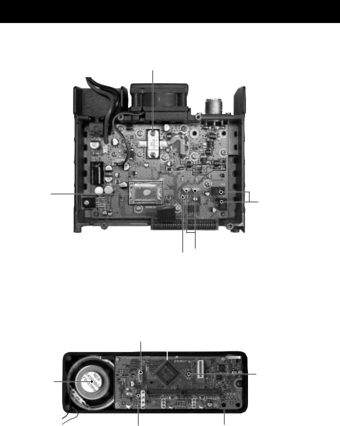
SECTION 2 INSIDE VIEWS
•MAIN UNIT
AF power amplifier (Q23: RD70HVF1)
 Antenna switching circuit (D12, D27: XB15A407, D19: XB15A308,
D16: HVU131TRF)
VCO circuit
2nd IF filter
(FI1: CFWS450F, FI2: CFWS450HT)
Reference oscillator |
|
1st IF filter |
|
||
(X1: CR-659) |
|
(FI3, FI4: FL-310) |
•LOGIC BOARD
System clock |
|
CPU |
|
||
(X1: CR-663) |
|
(IC7: HD6433876B53H) |
|
|
|
|
EEPROM |
Speaker |
(IC5: HN58X2432TI) |
Reset IC |
LOGIC board |
(IC4: S-80942ANMP-DD6) |
|
2 - 1

SECTION 3 DISASSEMBLY AND OPTION INSTRUCTIONS
• REMOVING THE COVER |
• REMOVING THE MAIN UNIT |
1 Unscrew 4 screws, MP10. |
1 Unscrew 11 screws, MP6, and 2 screws, MP7, and 2 |
2 Remove the cover in the direction of the arrow. |
screws, MP4. |
|
2 Unsolder 3 points, A, to remove the antenna connector. |
|
3 Remove the Main unit in the direction of the arrow. |
Cover
MP10
MP7
MP4
MP6
MP6
A J1
Main unit |
Chassis |
• REMOVING THE FRONT PANEL |
• OPTIONAL UNIT INSTALLATION |
1 Unscrew 3 screws, MP9. |
1 Install the optional unit as illustrated below. Insert it tight- |
2 Unplug J6 to separate front panel and chassis. |
ly to avoid bad contact. |
3 Remove the front panel in the direction of the arrow. |
|
4 Unplug J5 to separate fan and chassis. |
|
5 Unscrew 2 screws, MP6, to separate MP15 and chassis. |
|
MP6
J5 (MF1)
MP15
J6 (SP7)
Chassis
Front panel
MP9
3 - 1
Loading...