


IC-M411
Table of contents
 Loading...
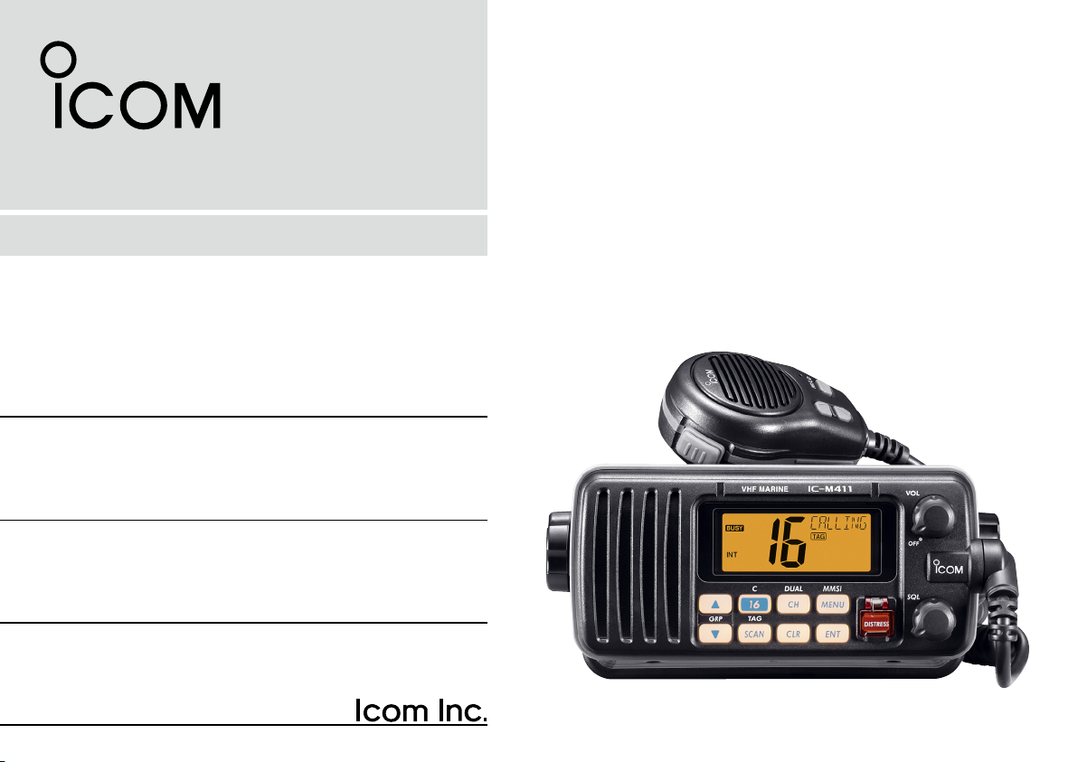
INSTRUCTION MANUAL
iM411
VHF MARINE TRANSCEIVER
i
FOREWORD
Thank you for purchasing this Icom product. The IC-M411
vhf marine transceiver is designed and built with Icom’s
state of the art technology and craftsmanship. With proper
care, this transceiver should provide you with years of trou
-
ble-free operation.
We want to take a couple of moments of your time to thank
you for making the IC-M411 your radio of choice, and hope
you agree with Icom’s philosophy of “technology first.” Many
hours of research and development went into the design of
your IC-M411.
D FEATURES
m Advanced receiver performance
m Easy to hear speaker
m Built-in DSC meets Class D requirement
m Rugged waterproof construction
m Favorite channel function
m AquaQuake water draining function
IMPORTANT
READ ALL INSTRUCTIONS carefully and completely
before using the transceiver.
SAVE THIS INSTRUCTION MANUAL — This in-
struction manual contains important operating instructions
for the IC-M411.
EXPLICIT DEFINITIONS
WORD DEFINITION
R WARNING!
CAUTION
NOTE
Pers o nal injur y, fi re h azard or elect r ic
shock may occur.
Equipment damage may occur.
Recommended for optimum use. No risk of
personal injury, fire or electric shock.
CLEA N THE T RANS C E I VER AND MI C R O P H ONE
THOROUGHLY WITH FRESH WATER after exposure
to water including salt water, otherwise, the keys and
switches may become inoperable due to salt crystalliza
-
tion.
Icom, Icom Inc. and the logo are registered trademarks of Icom Incor-
porated (Japan) in the United States, the United Kingdom, Germany, France,
Spain, Russia and/or other countries.

IN CASE OF EMERGENCY
If your vessel requires assistance, contact other vessels and
the Coast Guard by sending a Distress call on Channel 16.
USING CHANNEL 16
DISTRESS CALL PROCEDURE
1. “MAYDAY MAYDAY MAYDAY.”
2. “THIS IS ...............” (name of vessel)
3. Your call sign or other indication of the vessel (AND
9-digit DSC ID if you have one).
4. “LOCATED AT ...............” (your position)
5. The nature of the distress and assistance required.
6. Any other information which might facilitate the rescue.
Or, transmit your Distress call using digital selective calling
on Channel 70.
USING DIGITAL SELECTIVE CALLING (Ch 70)
DISTRESS CALL PROCEDURE
1. Wh i l e li f t in g up th e k e y co ver, p us h a n d h o l d
[DISTRESS] for 5 sec. until you hear 5 shor t beeps
change to one long beep.
2. Wait for an acknowledgment on Channel 70 from a
coast station.
• After the acknowledgement is received, Channel 16 is
automatically selected.
3. Push and hold
[PTT], then transmit the appropriate
information as listed above.
INSTALLATION NOTE
The installation of this equipment should be made in such a
manner as to respect the EC recommended electromagnetic
field exposure limits (1999/519/EC).
The maximum RF power available from this device is 25
watts. The antenna should be installed as high as possible
for maximum efficiency and that this insta llation height
should be at least 5 meters above ground (or accessible)
level. In the case where an antenna cannot be installed at
a reasonable height, then the transmitter should neither be
continuously operated for long periods if any person is within
5 meters of the antenna, nor operated at all if any person is
touching the antenna.
In all cases any possible risk depends on the transmitter
being activated for long periods. (Actual recommendation
limits are specified as an average of 6 minutes) Normally the
transmitter is not active for long periods of time. Some radio
licenses will require that a timer circuit automatically cuts the
transmitter after 1–2 minutes etc.
Similarly some types of transmitter, SSB, CW, AM, etc. have
a lower ‘average’ output power and the perceived risk is even
lower.
ii
iii
DOC
CE versions of the IC-M411 which display the “CE”
symbol on the serial number seal, comply with the
essential requirements of the European Radio and
Telecommunication Terminal Directive 1999/5/EC.
This warning symbol indicates that this equip-
ment ope rates in non-harmonised fre quency
bands and/or may be subject to licensing condi
-
tions in the country of use. Be sure to check that
you have the correct version of this radio or the
correct programming of this radio, to comply with
national licensing requirement.
DECLARATION
OF CONFORMITY
We Icom Inc. Japan
1-1-32, Kamiminami, Hirano-ku
Osaka 547-0003, Japan
Kind of equipment:
VHF MARINE TRANSCEIVER
This compliances is based on conformity with the following harmonised
standards, specifications or documents:
i)
EN 301 025-2 V1.2.1 (2004-09)
ii)
EN 301 025-3 V1.2.1 (2004-09)
iii) EN 60945 2002
iv) EN 60950-1 2001
v) EN 300 698-2 V1.1.1 ( 2000-08)
vi) EN 300 698-3 V1.1.1 ( 2001-05)
Type-designation: iM411
Signature
Declare on our sole responsibility that this equipment complies with the
essential requirements of the Radio and Telecommunications Terminal
Equipment Directive, 1999/5/EC, and that any applicable Essential Test
Suite measurements have been performed.
Version (where applicable):
0560
Authorized representative name
Place and date of issue
26th Sep. 2007
• List of Country codes (ISO 3166-1)
1 Austria AT
2 Belgium BE
3 Bulgaria BG
4 Croatia HR
5 Czech Republic CZ
6 Cyprus CY
7 Denmark DK
8 Estonia EE
9 Finland FI
10 France FR
11 Germany DE
12 Greece GR
13 Hungary HU
14 Iceland IS
15 Ireland IE
16 Italy IT
17 Latvia LV
18 Liechtenstein LI
19 Lithuania LT
20 Luxembourg LU
21 Malta MT
22 Netherlands NL
23 Norway NO
24 Poland PL
25 Portugal PT
26 Romania RO
27 Slovakia SK
28 Slovenia SI
29 Spain ES
30 Sweden SE
31 Switzerland CH
32 Turkey TR
33 United Kingdom GB
Country Codes Country Codes

iv
TABLE OF CONTENTS
FOREWORD ..................................................................................... i
IMPORTANT ...................................................................................... i
EXPLICIT DEFINITIONS ................................................................... i
IN CASE OF EMERGENCY ............................................................. ii
INSTALLATION NOTE ...................................................................... ii
DOC ................................................................................................. iii
TABLE OF CONTENTS ................................................................... iv
PRECAUTIONS ................................................................................ v
1 OPERATING RULES ..................................................................1
2 PANEL DESCRIPTION ........................................................... 2–4
n Front panel ............................................................................... 2
n Microphone ..............................................................................3
n Function display ....................................................................... 4
3
BASIC OPERATION ...............................................................5–9
n Channel selection .................................................................... 5
n Receiving and transmitting ......................................................7
n Call channel programming ....................................................... 8
n Channel comments .................................................................. 8
n Microphone Lock function ........................................................ 9
n Display backlight ...................................................................... 9
n AquaQuake water draining function .........................................9
4
SCAN OPERATION ............................................................10–11
n Scan types .............................................................................10
n Setting TAG channels ............................................................11
n Starting a scan ....................................................................... 11
5
DUALWATCH/TRI-WATCH .......................................................12
n Description ............................................................................. 12
n Operation ...............................................................................12
6
DSC OPERATION ............................................................... 13–38
n MMSI code programming ......................................................13
n DSC address ID ..................................................................... 14
n
Position and time programming ....................................................17
n Position indication .................................................................. 18
n Distress call ...........................................................................18
n Transmitting DSC calls ...........................................................21
n Receiving DSC calls ..............................................................32
n Received messages ..............................................................36
n Automatic acknowledgement ................................................ 38
n Offset time .............................................................................38
7
SET MODE .......................................................................... 39–41
n Set mode programming .........................................................39
n Set mode items ...................................................................... 40
8
CONNECTIONS AND MAINTENANCE..............................42–45
n Connections ........................................................................... 42
n Antenna .................................................................................43
n Fuse replacement ..................................................................43
n Cleaning................................................................................. 43
n Supplied accessories ............................................................. 43
n Mounting the transceiver .......................................................44
n Optional MB-69 installation .................................................... 45
9
TROUBLESHOOTING .............................................................. 46
10 SPECIFICATIONS AND OPTION .......................................47–49
n Specifications......................................................................... 47
n Option .................................................................................... 49
11
CHANNEL LIST ..................................................................50–51
12 TEMPLATE ............................................................................... 53

v
RWARNING! NEVER connect the transceiver to an
AC outlet. This may pose a fire hazard or result in an electric
shock.
NEVER connect the transceiver to a power source of more
than 16 V DC or use reverse polarity. This will ruin the trans
-
ceiver.
NEVER cut the DC power cable between the DC plug at
the back of the transceiver and fuse holder. If an incorrect
connection is made after cutting, the transceiver may be
damaged.
NEVER place the transceiver where normal operation of the
vessel may be hindered or where it could cause bodily injury.
KEEP the transceiver at least 1 m away from the ship’s
navigation compass.
DO NOT use or place the transceiver in areas with tem-
peratures below –20°C or above +60°C or, in areas subject
to direct sunlight, such as the dashboard.
AVOID the use of chemical agents such as benzine or al-
cohol when cleaning, as they may damage the transceiver
surfaces. If the transceiver becomes dusty or dirty, wipe it
clean with a soft, dry cloth.
BE CAREFUL! The transceiver rear panel will become
hot when operating continuously for long periods.
Place the transceiver in a secure place to avoid inadvertent
use by children.
BE CAREFUL! The transceiver employs waterproof
construction, which corresponds to IPX7 of the international
standard IEC 60529 (2001). However, once the transceiver
has been dropped, waterproofing cannot be guaranteed due
to the fact that the case may be cracked, or the waterproof
seal damaged, etc.
Icom optional equipment is designed for optimal perfor
-
mance when used with this transceiver. We are not respon
-
sible for the transceiver being damaged or any accident
caused when using non-Icom optional equipment.
PRECAUTIONS

1
1
OPERATING RULES
D PRIORITIES
• Read all rules and regulations pertaining to priorities and
keep an up-to-date copy handy. Safety and Distress calls
take priority over all others.
• You must monitor Channel 16 when you are not operating
on another channel.
• False or fraudulent distress signals are prohibited and pun
-
ishable by law.
D PRIVACY
• Information overheard but not intended for you cannot law-
fully be used in any way.
• Indecent or profane language is prohibited.
D RADIO LICENSES
(1) SHIP STATION LICENSE
You must have a current radio station license before using
the transceiver. It is unlawful to operate a ship station which
is not licensed.
Inquire through your dealer or the appropriate government
agency for a Ship-Radiotelephone license application. This
government-issued license states the call sign which is your
craft’s identification for radio purposes.
(2) OPERATOR’S LICENSE
A Restricted Radiotelephone Operator Permit is the license
most often held by small vessel radio operators when a radio
is not required for safety purposes.
The Restricted Radiotelephone Operator Permit must be
posted or kept with the operator. Only a licensed radio op
-
erator may operate a transceiver.
However, non-licensed individuals may talk over a trans
-
ceiver if a licensed operator starts, supervises, ends the call
and makes the necessary log entries.
Keep a copy of the current government rules and regulations
handy.
1
2
PANEL DESCRIPTION
2
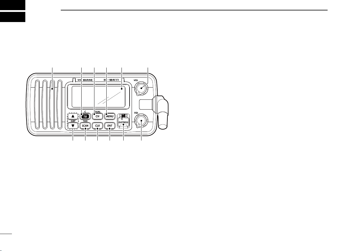
n Front panel
Function
display (p. 4)
Speaker
i !0o
weu y t r
q
q POWER/VOLUME CONTROL [VOL]
➥ Rotate to turn the transceiver power ON or OFF.
➥ Rotate to adjust the audio level.
w SQUELCH CONTROL [SQL] (p. 7)
Rotate to set the squelch threshold level.
e DISTRESS KEY [DISTRESS] (p. 18)
Push and hold for 3 sec. to transmit a distress call.
r ENTER KEY [ENT]
Sets the DSC menu, a channel comment, etc. when
pushed.
t CLEAR KEY [CLR]
Push to cancel the entered function and exits the condi
-
tion when pushed.
y SCAN/TAG CHANNEL KEY [SCAN•TAG] (p. 11)
➥ Push to start and stop the normal or priority scan when
tag channels are programmed.
➥ Push and hold for 1 sec. to set or clear the displayed
channel as a tag (scanned) channel.
➥ While pushing [HI/LO] located on the microphone,
push and hold for 3 sec. to set or clear all tag channels
in the selected channel group.
u CHANNEL UP/DOWN KEYS [s]/[t]•[GRP]
➥ Push to select the operating channels, Set mode set-
tings, DSC menu items, etc. (pgs. 5, 6, 13, 39)
➥ Push both keys to select a channel group in sequence.
(p. 6)
• EUR version has International channels only and this func-
tion is not available.
➥ Push to select the desired digit or character.
(pgs. 8, 13, 14, 17)
➥ While pushing [SCAN•TAG], push to adjust the bright-
ness of the LCD and key backlight. (p. 9)
➥ While pushing and holding both keys, turn power ON to
activates the AquaQuake function. (p. 9)
3
2
PANEL DESCRIPTION
i CHANNEL 16/CALL CHANNEL KEY [16•C]
➥ Push to select Channel 16. (p. 5)
➥ Push and hold for 1 sec. to select call channel. (p. 5)
• “CALL” appears when call channel is selected.
➥ Push and hold for 3 sec. to enter the call channel pro-
gramming condition when the call channel is selected.
(p. 8)
➥ While pushing [CH•DUAL], push to enter the channel
comment programming condition. (p. 8)
➥
While turning power ON, push to enter set mode. (p. 39)
o CHANNEL/DUALWATCH/TRI-WATCH KEY [CH•DUAL]
➥ Push to select the regular channel. (pgs. 5, 6)
➥ Push and hold for 1 sec. to start dualwatch or tri-watch.
(p. 12)
➥ Push to stop dualwatch or tri-watch when either is acti-
vated. (p. 12)
!0 DSC MENU KEY [MENU] (p. 13)
Push to toggle the DSC menu ON or OFF.
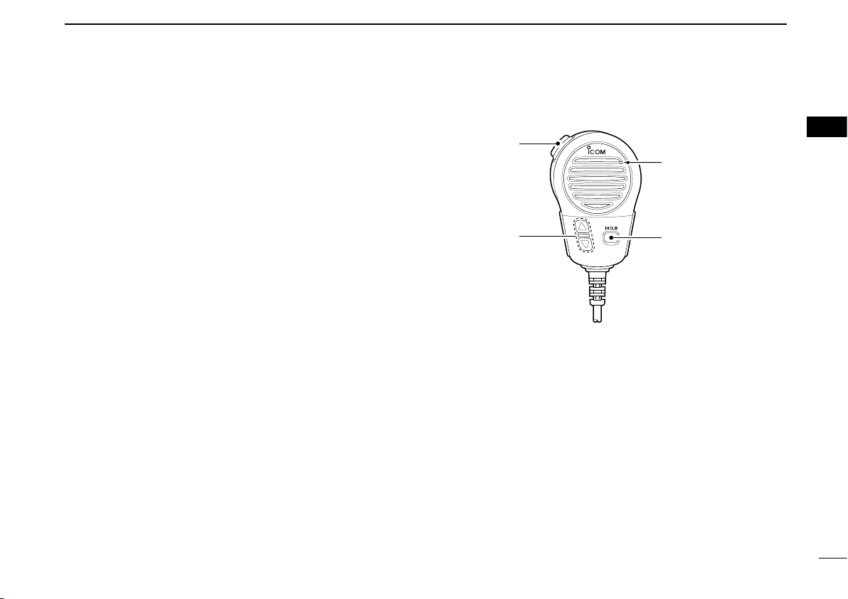
n Microphone
Microphone
q
e
w
q PTT SWITCH [PTT]
Push and hold to transmit; release to receive. (p. 7)
w CHANNEL UP/DOWN KEYS [Y]/[Z]
➥ Push to select the operating channels, Set mode set-
tings, DSC menu items, etc. (pgs. 5, 6, 13, 39)
➥ Checks TAG channels, changes scanning direction or
resumes the scan manually during scan. (p. 11)
➥ Push to select the desired digit or character.
(pgs. 8, 13, 14, 17)
e TRANSMIT POWER KEY [HI/LO]
➥ Push to toggle the output power high and low. (p. 7)
• Some channels are set to low power only.
➥
While pushing and holding [HI/LO], turn power ON to
toggle the Microphone Lock function ON and OFF. (p. 9)
2

4
2
PANEL DESCRIPTION
n Function display
!1
!2
r
q
tu
!0
o
i
w
e
y
q CHANNEL COMMENT INDICATOR
➥
‘Latitude,’ ‘Longitude’ and UTC time data scroll in sequence.
➥ Channel comment appears and scrolls (if programmed)
for about 10 sec. after the channel selection
. (p. 8)
➥
“DSC” appears when DSC channel group is in use; “ATIS”
appears when ATIS channel group is in use. (p. 6)
➥ “SCAN 16” appears during Priority scan; “SCAN” ap-
pears during Normal scan. (p. 11)
➥ “DW 16” appears during Dualwatch; “TW 16” appears
during Tri-watch. (p. 12)
➥
In Set mode, indicates and scrolls the selected item. (p. 39)
w TAG CHANNEL INDICATOR (p. 11)
Appears when a TAG channel is selected.
e DUPLEX INDICATOR (p. 6)
Appears when a duplex channel is selected.
r LOW BATTERY INDICATOR
Appears when the battery voltage drops to approx. 10 V
DC or below.
t DSC INDICATOR
Indicates the DSC status.
• “DSC” appears when a DSC call is received. (pgs. 22, 32)
• “POS REPLY” appears when a Position Reply call is received.
(p. 35)
y GPS INDICATOR
➥ Appears while valid position data is received.
➥ Blinks when invalid position data is received.
➥ Disappears when no GPS receiver is connected.
u CHANNEL NUMBER READOUT
➥ Indicates the selected operating channel number.
• “A” appears when a simplex channel is selected.
➥ In Set mode, indicates the selected condition. (p. 39)
i LOW POWER INDICATOR (p. 7)
Appears when low power is selected.
o CHANNEL GROUP INDICATOR (p. 6)
Indicates whether an International “
INT” or U.S.A. “USA”
channel is in use. (Depends on version)
!0 CALL CHANNEL INDICATOR (p. 5)
Appears when the call channel is selected.
!1 BUSY INDICATOR (p. 7)
Appears when receiving a signal or when the squelch
opens.
!2 TRANSMIT INDICATOR (p. 7)
Appears while transmitting.
5
3
BASIC OPERATION
2
3
n Channel selection
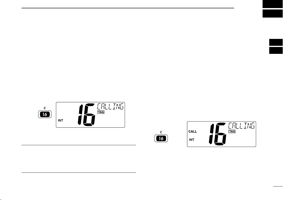
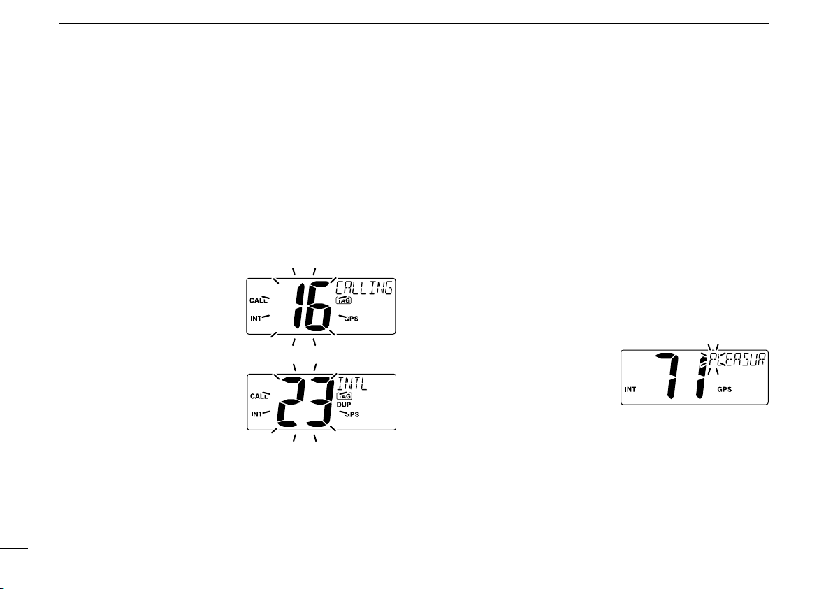
ï Channel 16
Channel 16 is the distress and safety channel. It is used for
establishing initial contact with a station and for emergency
communications. Channel 16 is monitored during both Du
-
alwatch and Tri-watch. While standing by, you must monitor
Channel 16.
➥ Push [16•C] momentarily to select Channel 16.
➥ Push [CH•DUAL] to return to the condition before select-
ing Channel 16, or push
[Y] or [Z] to select an operating
channel.
Push
Convenient!
When the Favorite channel function is turned ON (p. 41),
[Y]/[Z] keys on the microphone select the favorite channels
in the selected channel group in sequence when pushed.
• The favorite channels are set by the TAG channel setting. (p. 11)
ï Call channel
Each regular channel group has a separate leisure-use call
channel. The call channel is monitored during Tri-watch. The
call channels can be programmed (p. 8) and are used to
store your most often used channel in each channel group
for quick recall.
➥ Push and hold [16•C] for 1 sec. to select the call channel
of the selected channel group.
• “CALL” and call channel number appear.
• Each channel group may have an independent call channel
after programming a call channel. (p. 8)
➥ Push [CH•DUAL] to return to the condition before select-
ing call channel, or push
[Y] or [Z] to select an operating
channel.
Push and hold
for 1 sec.
6
3
BASIC OPERATION
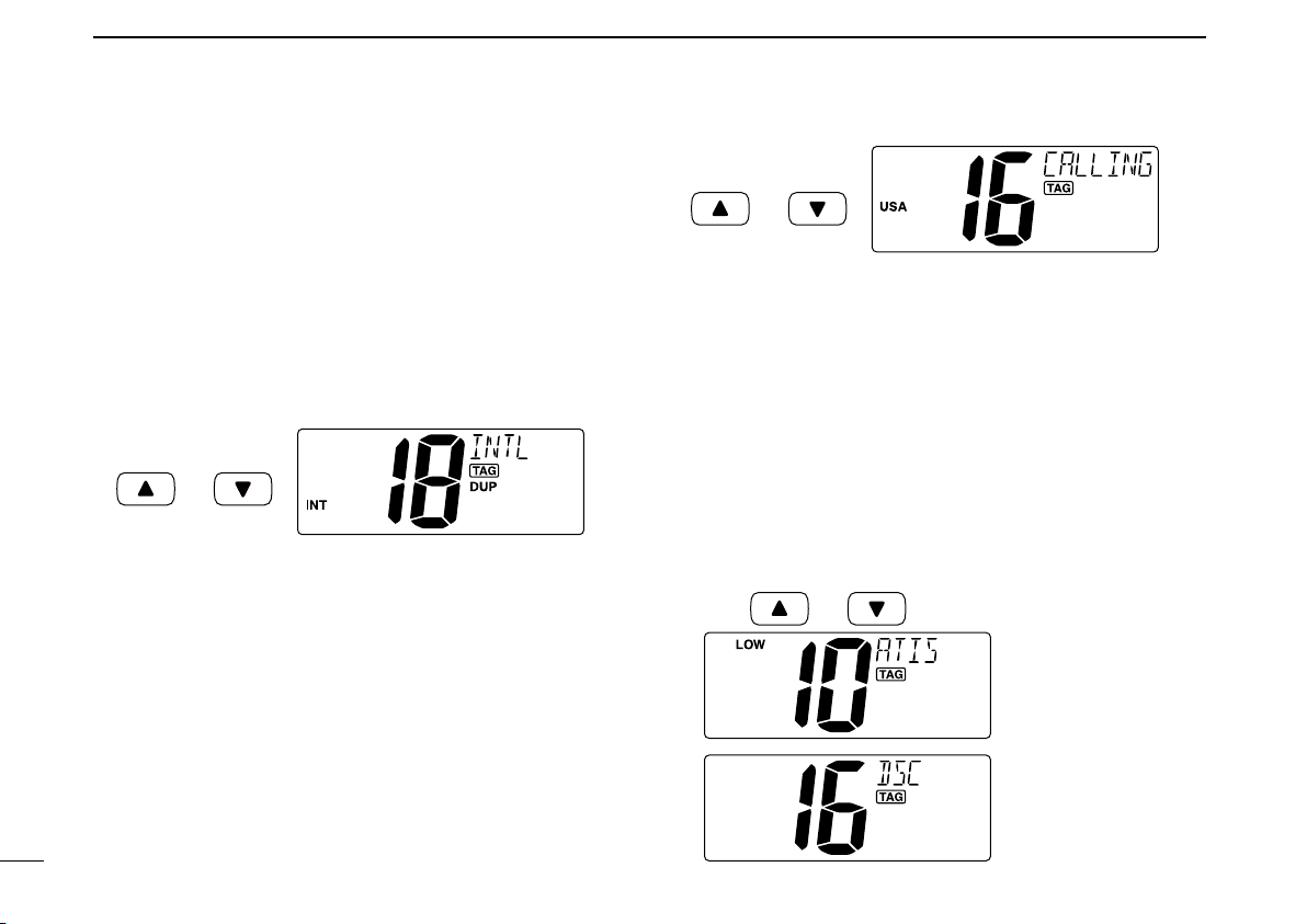
ï International channels
There are pre-programmed 57 (EUR version,) 59 (U.K. ver-
sion,) 58 (Holland version) or 56 (FRG version) International
channels for the IC-M411.
q Push [CH•DUAL] to select a regular channel.
w Push both [s] and [t] on the transceiver to change the
channel group, if necessary.
• EUR version has International channels only and this function
is not available.
e Push [Y] or [Z] to select a channel.
• “DUP” appears for duplex channels.
Push
and
ï U.S.A. channels (U.K. version only)
For U.K. version, there are pre-programmed 61 U.S.A. chan
-
nels in addition to 59 International channels.
q Push [CH•DUAL] to select a regular channel.
w Push both [s] and [t] on the transceiver to change the
channel group, if necessary.
• International and U.S.A. channels can be selected in sequence.
e Push [Y] or [Z] to select a channel.
• “DUP” appears for duplex channels.
Push
and
ï ATIS and DSC channels
(Holland and FRG versions only)
For Holland and FRG version, there are pre-programmed 57
ATIS and 57 DSC* channels in addition to 58 (Holland ver
-
sion) or 56 (FRG version) International channels.
q Push [CH•DUAL] to select a regular channel.
w Push both [s] and [t] on the transceiver to change the
channel group, if necessary.
• International, ATIS and DSC* channels can be selected in se-
quence.
e Push [Y] or [Z] to select a channel.
• “DUP” appears for duplex channels.
Push and
ATIS channel
DSC channel*
*FRG version only
7
3
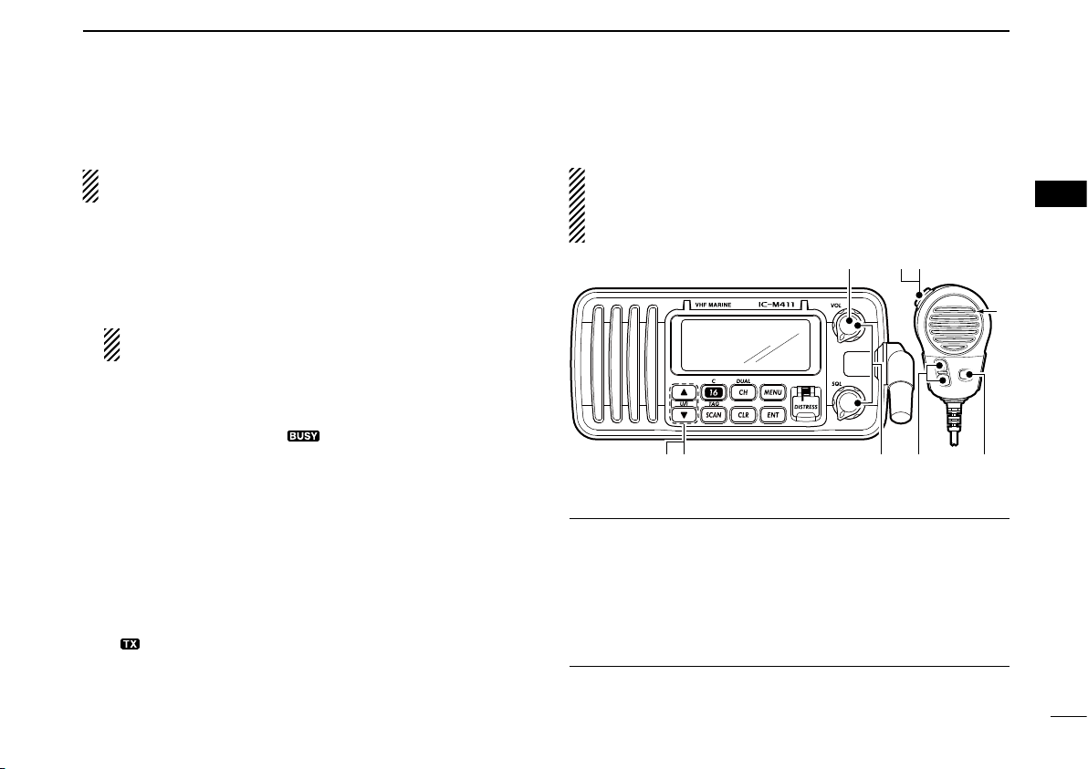
BASIC OPERATION
3
n Receiving and transmitting
CAUTION: Transmitting without an antenna may dam-
age the transceiver.
q Rotate [VOL] to turn power ON.
w Set the audio and squelch levels.
➥Rotate [SQL] fully counterclockwise in advance.
➥Rotate [VOL] to adjust the audio output level.
➥Rotate [SQL] clockwise until the noise disappears.
While in the DSC operation, please make sure you set
the squelch correctly.
e Push both [Y] and [Z] on the transceiver to change the
channel group. (p. 6)
r
Push [Y] or [Z] to select the desired channel. (pgs. 5, 6, 50)
• When receiving a signal, “ ” appears and audio is emitted
from the speaker.
• Further adjustment of [VOL] may be necessary.
t Push [HI/LO] on the microphone to select the output
power if necessary.
• “LOW” appears when low power is selected.
• Choose low power for short range communications, choose
high power for longer distance communications.
• Some channels are for low power only.
y Push and hold [PTT] to transmit, then speak into the mi-
crophone.
• “ ” appears.
• Channel 70 cannot be used for transmission other than DSC.
u Release [PTT] to receive.
IMPORTANT: To maximize the readability of your trans-
mitted signal, pause a few sec. after pushing
[PTT], hold
the microphone 5 to 10 cm from your mouth and speak at
a normal voice level.
u
w
re
M
q
y
r
t
M: Microphone
4 NOTE for TOT (Time-out Timer) function
The TOT function inhibits continuous transmission over a
preset time period after the transmission starts.
A beep sounds 10 sec. before the TOT function activates, to
indicate the transmission will be shut down and “TOT” ap
-
pears on the channel comment indicator. Transmission is not
possible for 10 sec. after this transmission shut down.
8
3
BASIC OPERATION
n Call channel programming
You can program the call channel with your most often-used
channels in each channel group for quick recall.
q Push both [Y] and [Z] on the transceiver one or more
times to select the desired channel group (INT, USA, ATIS
or DSC) to be programmed.
w Push and hold [16•C] for 1 sec. to select the call channel
of the selected channel group.
• “CALL” and call channel number appear.
e Push and hold [16•C] again
for 3 sec. (until a long beep
changes to 2 short beeps)
to e nter th e call ch annel
programming condition.
• Channel number starts blink-
ing.
r Push [Y] or [Z] to select
the desired channel.
t Push [16•C] to program the
disp layed ch annel as the
call channel.
• Push [CLR] to cancel.
• The channel number stops blinking.
n Channel comments
Memor y channels can be labeled with alphanumeric com-
ments of up to 10 characters each for easy channel recogni
-
tion.
Comment is indicated at the channel comment indicator for
about 10 sec. after the channel selection, and the comment,
more than 7 characters long, automatically scrolls.
Capital letters, small letters (except f, j, k, p, s, v, x, z), 0 to 9,
some symbols (= M + – . /) and space can be used.
q Select the desired channel.
• Cancel Dualwatch, Tri-watch or Scan in advance.
w While pushing [CH•DUAL], push [16•C] to edit the chan-
nel comment.
• A cursor and the first charac-
ter start blinking alternately.
e Select the desired charac-
ter by pushing
[Y] or [Z].
• Push [CH•DUAL] or [16•C]
to move the cursor forward or
backward, respectively.
r Repeat step e to input all characters.
t Push [ENT] to input and set the comment.
• Push [CLR] to cancel and exit the condition.
• The cursor and the character stop blinking.
y Repeat steps q to t to program other channel com-
ments, if desired.

9
3
BASIC OPERATION
3
n Microphone Lock function
The Microphone Lock function electrically locks [Y]/[Z] on
the supplied microphone. This prevents accidental channel
changes and function access.
➥ While pushing [HI/LO] on the microphone, turn power ON
to toggle the Microphone Lock function ON and OFF.
[HI/LO]
[Y]/[Z]
n Display backlight
The function display and keys can be backlit for better visibil-
ity under low light conditions.
Display backlight is also adjustable via the Set mode. (p. 41)
➥ While pushing [SCAN•TAG], push [Y] or [Z] to adjust
the brightness of the LCD and key backlight.
• The backlight is adjustable in 4 levels and OFF.
n AquaQuake water draining
function
The IC-M411 uses a technology to clear water away from
the speaker grill: AquaQuake. AquaQuake helps drain water
away from the speaker housing (water that might otherwise
muffle the sound coming from the speaker). The IC-M411
emits a vibrating noise when this function is being used.
➥ While pushing and holding both [Y] and [Z] on the trans-
ceiver, turn power ON.
• A low beep tone sounds while [Y] and [Z] keys are pushed
and held to drain water, regardless of [VOL] control setting.
• The transceiver never accepts a key operation while the
Aqua-
Quake function is activated.
10
SCAN OPERATION
4
n Scan types
Scanning is an efficient way to locate signals quickly over a
wide frequency range. The transceiver has Priority scan and
Normal scan.
Set the TAG channels (scanned channel) before scanning.
Clear the TAG channels which inconveniently stop scanning,
such as those for digital communication use. (Refer to right
page for details.)
Choose Priority or Normal scan in Set mode. (p. 40)
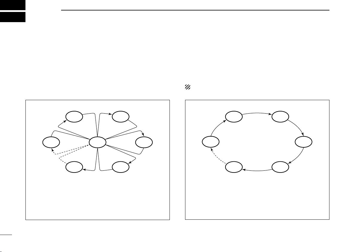
PRIORITY SCAN
CH 06
CH 01
CH 16
CH 02
CH 05 CH 04
CH 03
Priority scan searches through all TAG channels in se-
quence while monitoring Channel 16. When a signal is
detected on Channel 16, scan pauses until the signal
disappears; when a signal is detected on a channel other
than Channel 16, scan becomes Dualwatch until the sig
-
nal disappears.
NORMAL SCAN
CH 01 CH 02
CH 06
CH 05 CH 04
CH 03
Normal scan, like Priority scan, searches through all TAG
channels in sequence. However, unlike Priority scan,
Channel 16 is not checked unless Channel 16 is set as a
TAG channel.
11
4
SCAN OPERATION
4
n Setting TAG channels
For more efficient scanning, add the desired channels as
TAG channels or clear the TAG for unwanted channels.
Channels that are not tagged will be skipped during scan
-
ning. TAG channels can be assigned to each channel group
(INT, USA, ATIS or DSC) independently.
q Push both [Y] and [Z ] to select the desired channel
group, if desired.
w Select the desired channel to be set as a TAG channel.
e Push and hold [SCAN•TAG] for 1 sec. to set the displayed
channel as a TAG channel.
• “ ” appears in the display.
r To cancel the TAG channel setting, repeat step e.
• “ ” disappears.
✓ Clearing (or setting) all tagged channels
While pushing
[HI/LO] on the microphone, push and hold
[SCAN•TAG] for 3 sec. (until a long beep changes to 2 short
beeps) to clear all TAG channels in the channel group.
• Repeat above procedure to set all TAG channels.
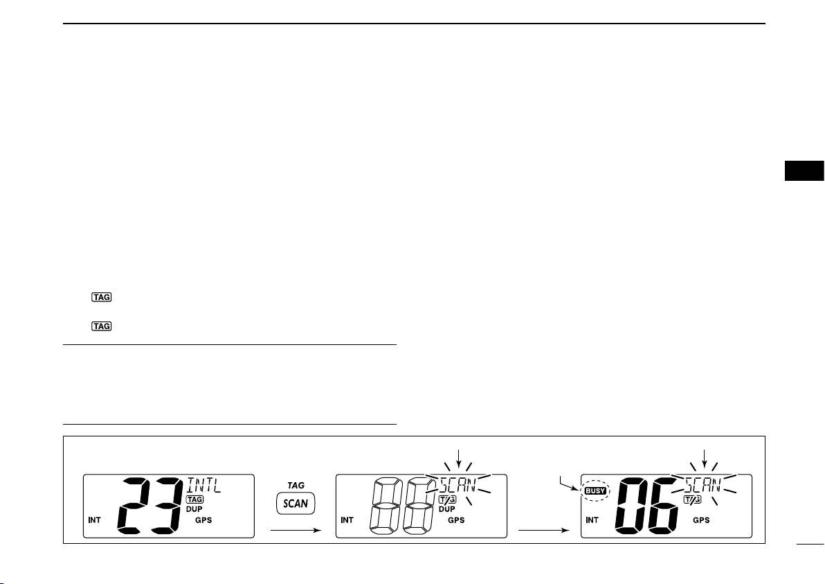
n Starting a scan
Set scan type (Priority or Normal scan) and scan resume
timer in advance, using Set mode. (p. 40)
q Push both [Y] and [Z ] to select the desired channel
group, if desired.
w Set TAG channels as described at left.
e Make sure the squelch is closed to start a scan.
r Push [SCAN•TAG] to start Priority or Normal scan.
• “SCAN” blinks at the channel comment indicator during scan-
ning. (During Priority scan, “16” appears beside the blinking
“SCAN” indication.)
• A beep tone sounds and “16” blinks at the channel comment in-
dicator when a signal is received on Channel 16 during Priority
scan.
• When a signal is detected, scan pauses until the signal disap-
pears or resumes after pausing 5 sec. according to Set mode
setting. (Channel 16 is still monitored during Priority scan.)
• P ush [Y] or [ Z ] t o ch eck th e sc annin g TAG c hanne ls, to
change the scanning direction or resume the scan manually.
t To stop the scan, repeat step r.
[Example]: Starting a Normal scan.
Push
Scan starts.
When a signal is
received.
BlinksBlinks
Appears
12
DUALWATCH/TRI-WATCH
5
n Description
Dualwatch monitors Channel 16 while you are receiving on
another channel; Tri-watch monitors Channel 16 and the
call channel while receiving another channel. Dualwatch/Tri-
watch is convenient for monitoring Channel 16 when you are
operating on another channel.
n Operation
q Select Dualwatch or Tri-watch in Set mode. (p. 40)
w Push [Y] or [Z] to select the desired channel.
e Push and hold [CH•DUAL] for 1 sec. to start Dualwatch
or Tri-watch.
• “DW” blinks during Dualwatch; “TW” blinks during Tri-watch.
• A beep tone sounds and “16” blinks when a signal is received
on Channel 16.
r To cancel Dualwatch/Tri-watch, push [CH•DUAL] again.
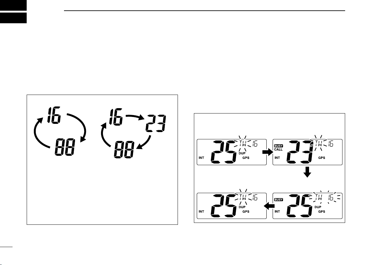
DUALWATCH/TRI-WATCH SIMULATION
Dualwatch Tri-watch
Call channel
• If a signal is received on Channel 16, Dualwatch/Tri-
watch pauses on Channel 16 until the signal disappears.
• If a signal is received on the call channel during Tri-
watch, Tri-watch becomes Dualwatch until the signal dis
-
appears.
• To transmit on the selected channel during Dualwatch/
Tri-watch, push and hold
[PTT].
[Example]: Operating Tri-watch on INT Channel 25
q Tri-watch starts. w Signal is received on
call channel.
e Signal is received on
Channel 16 takes priority.
r Tri-watch resumes after the
signal disappears.

13
6
DSC OPERATION
5
6
n MMSI code programming
The 9-digit MMSI (Maritime Mobile Service Identity: DSC
self ID) code can be programmed at power ON.
This code programming can be performed only once.
After the code programming, it can be changed only
by your dealer or distributor.
q While pushing [MENU], turn power ON to enter MMSI
code programming condition.
• Turn power OFF in advance.
w After the display appears, release [MENU].
e Push [MENU] to enter the DSC menu.
r Push [Y] or [Z] to select “MMSI” and push [ENT].
• A cursor starts blinking.
t Input the specified MMSI code by pushing [Y] or [Z].
• Push [CH•DUAL] or [16•C] to move the cursor forward or back-
ward, respectively.
y After inputting the 9-digit MMSI code, push [ENT].
• “CONFIRMATION” scrolls at the channel comment indicator.
Scrolls
u Push [ENT], then input the same MMSI code as step t
for the confirmation.
i
Push [ENT] to set the code.
• Returns to the normal operation.
• Push [CLR] to cancel and exit the condition.
• If the different code is input, “INCORRECT” appears. Push
[ENT] and try steps t to u again.
D MMSI code check
The 9-digit MMSI (DSC self ID) code can be checked.
➥
Push [MENU] for 1 sec. to display the 9-digit MMSI (DSC
self ID) code.
• The MMSI code is displayed and scrolls at the channel com-
ment indicator.
• When no MMSI code is programmed, “NO MMSI” appears and
warning alarm sounds.
Scrolls
14
6
DSC OPERATION
n DSC address ID
A total of 100 DSC address IDs (9-digit) can be programmed
and named with up to 10 characters.
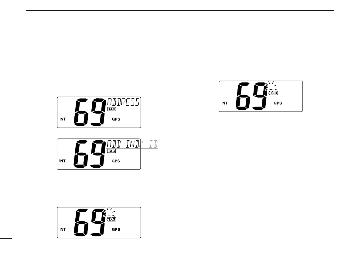
D Programming Address ID
q Push [MENU] to enter the DSC menu.
w Push [Y] or [Z] to select “ADDRESS,” push [ENT].
e Push [Y] or [Z] to select “ADD INDV ID,” push [ENT].
Scrolls
r Push [Y] or [Z] to set the 9-digit Individual ID, push
[ENT].
• Push [CH•DUAL] or [16•C] to move the cursor forward or back-
ward, respectively.
• Push [CLR] to cancel and exit the condition.
t Push [Y] or [Z] to set up to a 10-character ID name.
• Push [CH•DUAL] or [16•C] to move the cursor forward or back-
ward, respectively.
• Push [CLR] to cancel and exit the condition.
y Push [ENT] to program and returns to the normal opera-
tion.
Loading...