


INSTRUCTION MANUAL
VHF TRANSCEIVER
iV8
This device complies with Part 15 of the FCC rules. Operation is subject to the following two conditions: (1) This device may not cause harmful interference, and (2) this device must accept any interference received, including interference that may cause undesired operation.

FOREWORD
Thank you for purchasing the IC-V8 FM transceiver. This transceiver is designed for those who require quality, performance and outstanding reliability under the most demanding conditions.
D FEATURES
5.5 W of ample output power
MIL-STD810 grade durability
CTCSS and DTCS encoder/decoder standard
Optional DTMF decoder
IMPORTANT
READ ALL INSTRUCTIONS carefully and completely before using the transceiver.
SAVE THIS INSTRUCTION MANUAL— This instruction manual contains important operating instructions for the transceiver.
Icom, Icom Inc. and the 
 are registered trademarks of Icom Incorporated (Japan) in the United States, the United Kingdom, Germany, France, Spain, Russia and/or other countries.
i

EXPLICIT DEFINITIONS
The explicit definitions below apply to this instruction manual.
WORD |
DEFINITION |
R WARING
Personal injury, fire hazard or electric shock may occur.
CAUTION Equipment damage may occur.
NOTE
If disregarded, inconvenience only. No risk of personal injury, fire or electric shock.
PRECAUTIONS
RWARNING! NEVER hold the transceiver so that the antenna is very close to, or touching exposed parts of the body, especially the face or eyes, while transmitting. The transceiver will perform best if the microphone is 5 to 10 cm (2 to 4 inches) away from the lips and the transceiver is vertical.
RWARNING! NEVER operate the transceiver with a headset or other audio accessories at high volume levels. Hearing experts advise against continuous high volume operation. If you experience a ringing in your ears, reduce the volume or discontinue use.
NEVER connect the transceiver to a power source that is DC fused at more than 5 A. Accidental reverse connection will be protected by this fuse, but higher fuse values will not give any protection against such accidents and the transceiver will be ruined.
ii

PRECAUTIONS— continued
NEVER attempt to charge alkaline or dry cell batteries. Be aware that external DC power connections will charge batteries inside the battery case. This will damage not only the battery case but also the transceiver.
DO NOT push the PTT when not actually desiring to transmit.
Place the unit in a secure place to avoid inadvertent use by children.
DO NOT operate the transceiver near unshielded electrical blasting caps or in an explosive atmosphere.
AVOID using or placing the transceiver in direct sunlight or in areas with temperatures below –10°C (+14˚F) or above +60°C (+140˚F).
The use of non-Icom battery packs/chargers may impair transceiver performance and invalidate the warranty.
Even when the transceiver power is OFF, a slight current still flows in the circuits. Remove the battery pack or case from the transceiver when not using it for a long time. Otherwise, the battery pack or installed Ni-Cd batteries will become exhausted.
For USA only:
Caution: Changes or modifications to this transceiver, not expressly approved by Icom Inc., could void your authority to operate this transceiver under FCC regulations.
iii

SUPPLIED ACCESSORIES
Accessories included with the transceiver:
q |
w |
t |
e |
y |
r |
q Antenna …………………………………………………… 1 w Belt clip …………………………………………………… 1 e 2251 OPT sheet ………………………………………… 1 r AC Adapter* ……………………………………………… 1 t Battery pack*/Battery case* …………………………… 1 y Battery charging stand* ………………………………… 1
*Not supplied with some versions.
iv

SAFETY TRAINING INFORMATION
CAUTION
To ensure that your exposure to RF electromagnetic energy is within the FCC allowable limits, always adhere to the following guidelines:
•DO NOT operate the radio without a proper antenna attached, as this may damage the radio and may also cause you to exceed FCC RF exposure limits. A proper antenna is the antenna supplied with this radio by the manufacturer or an antenna specifically authorized by the manufacturer for use with this radio.
•DO NOT transmit for more than 50% of total radio use time (“50% duty cycle”). Transmitting more than 50% of the time can cause FCC RF exposure compliance requirements to be exceeded. The radio is transmitting when the “TX indicator” is lit. You can cause the radio to transmit by pressing the “PTT” switch.
•ALWAYS use Icom authorized accessories (antennas, batteries, belt clips, speaker/mics, etc.). Use of unauthorized accessories can cause the FCC RF exposure compliance requirements to be exceeded.
v

•ALWAYS keep the antenna at least 2.5 cm (1 inch) away from the body when transmitting, and only use the Icom belt-clips which are listed in this manual when attaching the radio to your belt, etc. To provide the recipients of your transmission the best sound quality, hold the antenna at least 5 cm (2 inches) from your mouth, and slightly off to one side.
The information listed above provides the user with the information needed to make him or her aware of RF exposure, and what to do to assure that this radio operates within the FCC RF exposure limits of this radio. Electromagnetic Interference/Compatibility. During transmissions, your Icom radio generates RF energy that can possibly cause interference with other devices or systems. To avoid such interference, turn off the radio in areas where signs are posted to do so. DO NOT operate the transmitter in areas that are sensitive to electromagnetic radiation such as hospitals, aircraft, and blasting sites.
vi

TABLE OF CONTENTS
FOREWORD …………………………………………………………………… i IMPORTANT …………………………………………………………………… i EXPLICIT DEFINITIONS ……………………………………………………… ii PRECAUTIONS……………………………………………………………… ii–iii SUPPLIED ACCESSORIES ………………………………………………… iv SAFETY TRAINING INFORMATION ………………………………………v–vi
TABLE OF CONTENTS ………………………………………………… vii–viii
QUICK REFERENCE ……………………………………………………… I–VII
■Preparation …………………………………………………………… I–III
■Your first contact……………………………………………………… IV–V
■Repeater operation ……………………………………………………… VI
■Programming memory channels ……………………………………… VII
1ACCESSORIES …………………………………………………………… 1
■Accessory attachment …………………………………………………… 1
2PANEL DESCRIPTION ………………………………………………… 2–8
■Switches, controls, keys and connectors …………………………… 2–6
■Function display ……………………………………………………… 7–8
3BATTERY PACKS ……………………………………………………… 9–15
■Battery pack replacement ……………………………………………… 9
■Battery caution ………………………………………………………… 10
■Battery charging …………………………………………………… 11–13
■Charging NOTE ………………………………………………………… 14
■Battery case (optional for some versions) …………………………… 15
4BASIC OPERATION ………………………………………………… 16–20
■Power ON ……………………………………………………………… 16
■Setting a frequency ………………………………………………… 16–18
■Setting audio/squelch level …………………………………………… 18
■Receive and transmit …………………………………………………… 19
■Key lock function ……………………………………………………… 19
■Display type……………………………………………………………… 20
5REPEATER OPERATION …………………………………………… 21–24
■General ………………………………………………………………… 21
■Offset frequency ………………………………………………………… 22
■Subaudible tones …………………………………………………… 22–23
■Auto repeater function (USA versions only) ………………………… 24
vii

6 MEMORY/CALL OPERATION ……………………………………… 25–29
■ General ………………………………………………………………… 25 ■ Selecting a memory channel ………………………………………… 25 ■ Selecting the call channel ……………………………………………… 25 ■ Programming the memory/call channels …………………………… 26 ■ Channel name programming ………………………………………… 27 ■ Memory transferring ……………………………………………… 28–29
7 DTMF MEMORY ……………………………………………………… 30–31
■ Programming a DTMF code …………………………………………… 30 ■ Transmitting a DTMF code …………………………………………… 31 ■ DTMF transmission speed …………………………………………… 31
8 SCAN OPERATION ………………………………………………… 32–36
■ Scan types ……………………………………………………………… 32 ■ Programmed scan ……………………………………………………… 33 ■ Memory scan ……………………………………………………………34
■ Skip channels …………………………………………………………… 34 ■ Priority watch …………………………………………………………… 35 ■ Scan resume condition ………………………………………………… 36
9 SUBAUDIBLE TONES ……………………………………………… 37–40
■ Tone squelch ……………………………………………………… 37–38 ■ Pocket beep operation ………………………………………………… 39 ■ Tone scan ……………………………………………………………… 40
10 PAGER/CODE SQUELCH…………………………………………… 41–47
■ Pager function…………………………………………………………… 41 ■ Code programming ………………………………………………… 42–44 ■ Pager operation …………………………………………………… 45–46 ■ Code squelch …………………………………………………………… 47
11 OTHER FUNCTIONS ………………………………………………… 48–56
■ SET MODE …………………………………………………………… 48–50 ■ INITIAL SET MODE …………………………………………………… 51–55 ■ CPU reset ……………………………………………………………… 56
12 CLONING ………………………………………………………………… 57
13 OPTIONAL UNIT ……………………………………………………… 58–60
■Optional UT-108 installation …………………………………………… 58
■Optional MB-87 installation ……………………………………… 59–60
14 SPECIFICATIONS ………………………………………………………… 61
15 OPTIONS ……………………………………………………………… 62–63
1
2
3
4
5
6
7
8
9
10
11
12
13
14
15
viii

QUICK REFERENCE
■ Preparation
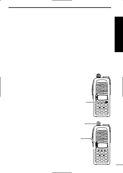
D Battery pack replacement
Before replacing the battery pack, push [POWER] for 1 sec. to turn the power OFF.
•Slide the battery release forward, then pull the battery pack upward with the transceiver facing away from you.
D Battery case— optional for some versions
When using a BP-208 BATTERY CASE attached to the transceiver, install 6 AA (R6) size alkaline batteries as illustrated below.
I
QUICK REFERENCE
D Charging with the BC-144/146
The optional BC-144 provides rapid charging, and the BC-146 provides regular charging of an optional battery pack with/without transceiver. The following is additionally required:
• An optional AC adapter. (An AD-99 is supplied with BC-144/146.)
Turn power OFF.
Check orientation for correct charging. (Insert together with AD-99.)
BC-144/146 +AD-99
• About AD-99
Attach the spacer (Spacer B/C) to the adapter (Spacer A) with orientation as illustrated in the diagram below.
Check orientation 
and
Spacer A 
Spacer B/C
•Attach the spacer (Spacer B/C) to the adapter with the orientation of the stamp “  ” pointing up.
Quick Reference
II

QUICK REFERENCE
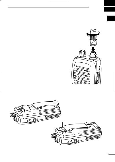
D Antenna
Attach the antenna to the transceiver as illustrated at right.
D Belt clip
Attach the belt clip to the transceiver as illustrated below.
To attach the belt clip
To release the belt clip
III
QUICK REFERENCE
■ Your first contact
Now that you have your IC-V8 ready, you are exited to get on the air. We would like to walk you through a few basic operational steps to make your first “On The Air” use an enjoyable experience.
D About default setting
The [VOL] control function can be traded with [Y]/[Z] keys function in INITIAL SET MODE. However, in this QUICK REFERENCE, the factory default setting ([VOL] controls audio output level) is used for simple instructions.
D Basic operation
1. Turning ON the transceiver
Although you have purchased a brand new transceiver, some settings may be changed from the factory defaults because of the QC process. Resetting the CPU is necessary to start from factory default.
While pushing [SQL] and [D•CLR], push [POWER] for 1 sec. to reset the CPU and turn power ON.
2. Adjusting output level
Rotate [VOL] to set the desired audio level.
3. Adjusting the squelch level
While pushing and holding [SQL], push [Y] or [Z] to set the squelch level.
[POWER]
[SQL] 
[D•CLR]
[VOL]
[Y]
[SQL]  [Z]
[Z]
Quick Reference
IV

QUICK REFERENCE
4. Tune the desired frequency
The up/down keys, [Y]/[Z], will allow you to tune to the frequency that you want to operate on. Page 18 will instruct you on how to adjust the tuning step.
Push [Y] or [Z] to adjust the frequency.
Direct frequency input from the keypad is also available.
To enter the desired frequency, enter 6-digits starting from the 100 MHz digit.
[Y]
[Z] [D•CLR]
Keypad 


•Enter three to five digits then push [#•ENT  ] to set the frequency.
•When a digit is mistakenly input, push [D.CLR] to abort inputting.
•Example 1— when entering 145.525 MHz
Push 


• Example 2— when entering 144.800 MHz
Push 


5. Transmit and receive
Push and hold [PTT] to transmit, then speak into microphone; release to receive.
V

QUICK REFERENCE
■ Repeater operation
1. Setting duplex
Push [A•FUNC], then [4•DUP] several times to select minus duplex or plus
duplex.
• The USA version has an auto repeater function, therefore, setting duplex is not
required. |
[A•FUNC] |
|
[4•DUP] |
2. Repeater tone
Push [A•FUNC], then [1•TONE] several times until “ ” appears, if required.
Quick Reference
[A•FUNC] 

[1•TONE]
VI

QUICK REFERENCE
■ Programming memory channels
The IC-V8 has a total of 107 memory channels (including 6 scan edges and 1 call channel) for storing often used operating frequency, repeater settings, etc.
1. Setting frequency
In VFO mode, set the desired operating frequency with other desired settings, such as repeater and subaudible tone.
2. Selecting a memory channel
Push [A•FUNC], [C•MR] then push [Y]or [Z] several times to select the desired
memory channel.
• “M” indicator and memory channel number blink.
[A•FUNC] 

[C•MR]
3. Writing a memory channel
Push [A•FUNC], then [C•MR] for 1 sec. to program.
•3 beeps sound
•Memory channel number automatically increases when continuing to push [C•MR] after programming.
VII
ACCESSORIES |
1 |
■ Accessory attachment |
1 |
D Antenna |
|
Attach the antenna to the transceiver as illustrated at right.
Keep the jack cover attached when jacks are not in use to avoid bad contacts.
D Belt clip
Attach the belt clip to the transceiver as illustrated below.
To attach the belt clip
To release the belt clip
1
2 PANEL DESCRIPTION
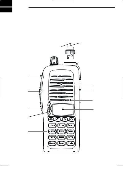
■Switches, controls, keys and connectors
 u q
u q

w
Speaker
e |
i |
|
Microphone
r
o
t
y
2

PANEL DESCRIPTION 2
2
qCONTROL DIAL [VOL]
Rotate to adjust the volume level.*
wPOWER SWITCH [POWER]
Push for 1 sec. to turn the power ON and OFF.
ePTT SWITCH [PTT]
Push and hold to transmit; release to receive.
rSQUELCH SWITCH [SQL]
Push and hold to force the squelch open and set the transceiver to the squelch level adjustable condition.
tUP/DOWN KEYS [Y]/[Z]*
Selects the operating frequency.*
yKEY PAD (pgs. 4–6)
Used to enter operating frequency, the DTMF codes, etc.
uANTENNA CONNECTOR
Connects the supplied antenna.
i[SP]/[MIC] JACK
Connect an optional speaker-microphone or headset, if desired. The internal microphone and speaker will not function when either is connected.
oFUNCTION DISPLAY (pgs 7, 8)
*The assigned function for [VOL] and [Y]/[Z] can be traded in
INITIAL SET MODE (pgs. 17, 53).
3

2 PANEL DESCRIPTION
D Key pad
[A•FUNC]
Access to secondary function.
[B•CALL]
Select the call channel. (p. 25)
[C•MR]
Selects a memory mode. (p. 25)
After pushing [A•FUNC], entering into memory programming/editing mode. (pgs. 26, 28)
After pushing [A•FUNC], programs/transfers VFO/memory or call channel contents into memory channel/VFO when pushed for 1 sec. (pgs. 26, 28)
[D•CLR]
Selects VFO mode, aborts direct frequency input, or cancels scanning, etc. (pgs. 16, 33)
[1•TONE]
Input digit “1” during frequency input, memory channel selection, etc. (pgs. 16, 25)
After pushing [A•FUNC], selects the subaudible tone function. (pgs. 21, 37)
[2•P.BEEP]
Input digit “2” during frequency input, memory channel selection, etc. (pgs. 16, 25)
After pushing [A•FUNC], turn the pocket beep function ON and OFF (p. 39)
[3•T.SCAN]
Input digit “3” during frequency input, memory channel selection, etc. (pgs. 16, 25)
After pushing [A•FUNC], starts the tone scanning. (pgs. 23, 40)
4
PANEL DESCRIPTION 2
D Key pad (Continued)
[4•DUP] |
|
|
2 |
||
Input digit “4” during frequency input, memory chan- |
||
nel selection, etc. (pgs. 16, 25) |
|
After pushing [A•FUNC], selects a duplex function (–duplex, +duplex, simplex). (p. 21)
[5•SCAN]
Input digit “5” during frequency input, memory channel selection, etc. (pgs. 16, 25)
After pushing [A•FUNC], starts scanning. (p. 33)
[6•SKIP]
Input digit “6” during frequency input, memory channel selection, etc. (pgs. 16, 25)
After pushing [A•FUNC], sets and cancels skip setting for memory skip scan during memory mode. (p. 34)
[7•PRIO]
Input digit “7” during frequency input, memory channel selection, etc. (pgs. 16, 25)
After pushing [A•FUNC], starts the priority watch. (p. 35)
[8•SET]
Input digit “8” during frequency input, memory channel selection, etc. (pgs. 16, 25)
After pushing [A•FUNC], enters into the SET MODE. (p. 48)
[9•HI/LO]
Input digit “9” during frequency input, memory channel selection, etc. (pgs. 16, 25)
After pushing [A•FUNC], switches between high and low output power. (p. 19)
5

2 PANEL DESCRIPTION
D Key pad (Continued)
[0•DTMF-M]
Input digit “0” during frequency input, memory channel selection, etc. (pgs. 16, 25)
After pushing [A•FUNC], enters into the DTMF memory mode. (p. 30)
[ •OPTION]
Selects an optional pager or code squelch operation mode. (p. 43)
[#•ENT  ]
]
Sets the frequency even if the full 6-digits of frequency have not been entered. (p. 16)
After pushing [A•FUNC], switches key pad lock function ON and OFF when pushed for 1 sec. Lock all keys, except [POWER], [PTT], [SQL] and audio level adjustment. (p. 19)
6

PANEL DESCRIPTION 2
■ Function display
q w |
e r t y u i o |
2 |
|
|
!5
!4 


 !3
!3 


 !0
!0


 !1
!1
!2
qFUNCTION INDICATOR
Appears while a secondary function is being accessed.
wSKIP CHANNEL INDICATOR
Appears when the selected memory channel is set as a “skip channel.” (p. 34)
eDUPLEX INDICATOR
Either “–” or “+” appears during repeater operation (p. 21).
rTONE ENCODER INDICATOR
Appears when tone encoder is in use. (p. 21)
t POCKET BEEP INDICATOR
Appears during pocket beep operation (p. 39).
yTONE SQUELCH INDICATOR
Appears when tone squelch is in use. (p. 37)
uDTCS INDICATOR
Appears when DTCS tone is in use. (p. 37)
iTRANSMIT INDICATOR
Appears during transmit. (p. 19)
7

2 PANEL DESCRIPTION
■ Function display (continued)
oSIGNAL INDICATOR
Appears when the channel is busy and shows receiving signal strength as below.
Weak RX Signal level Strong
!0LOW POWER INDICATOR
Appears when low output power is selected. (p. 19)
!1KEY LOCK INDICATOR (p. 19)
Appears when the key lock function is ON.
!2FREQUENCY READOUT
Shows operating frequency, channel number or channel names, depending on display type (p. 20).
!3MEMORY CHANNEL INDICATOR
Indicates the selected memory channel number or other items such as the call channel, etc. (p. 25)
!4MEMORY MODE INDICATOR
Appears while in memory mode or channel number indication mode. (p. 25)
!5AUTO POWER OFF INDICATOR
Appears while the auto power OFF function is activated. (p. 52)
8
 Loading...