


INSTRUCTION MANUAL
VHF FM REPEATER
iFR3100
UHF FM REPEATER
iFR4100

IMPORTANT
READ THIS INSTRUCTION MANUAL CAREFULLY before attempting to operate the re-
peater.
SAVE THIS INSTRUCTION MANUAL– This manual contains important safety and operating instructions for the IC-FR3100/FR4100 series.
EXPLICIT DEFINITIONS
WORD |
DEFINITION |
R WARNING |
Personal injury, fire hazard or electric |
|
shock may occur. |
CAUTION |
Equipment damage may occur. |
|
|
NOTE |
If disregarded, inconvenience only. |
No risk of personal injury, fire or |
|
|
electric shock. |
PRECAUTION
R WARNING HIGH VOLTAGE! NEVER attach an antenna or internal antenna connector during transmission. This may result in an electrical shock or burn.
RWARNING HIGH VOLTAGE! NEVER install the antenna in any place that a person can touch the antenna easily during transmission. This may result in an electrical shock or burn.
R NEVER apply AC to the [BATTERY] terminals on the repeater rear panel. This could cause a fire or damage the repeater.
RNEVER apply more than 16 V DC, such as a 24 V battery, to the [BATTERY] terminals on the repeater rear panel. This could cause a fire or damage the repeater.
R NEVER let metal, wire or other objects touch any internal part or connectors on the rear panel of the repeater. This may result in an electric shock.
R NEVER expose the repeater to rain, snow or any liquids.
AVOID using or placing the repeater in areas with temperatures below –25°C or above +55°C.
AVOID placing the repeater in excessively dusty environments or in direct sunlight.
AVOID putting anything on top of the repeater. This will obstruct heat dissipation.
Place the repeater in a secure place to avoid inadvertent use by children.
BE CAREFUL! The heatsink will become hot when operating the repeater continuously for long periods.
BE CAREFUL! If a linear amplifier is connected, set the repeater’s RF output power to less than the linear amplifier’s maximum input level, otherwise, the linear amplifier will be damaged.
Use Icom microphones only (optional). Other manufacturer’s microphones have different pin assignments, and connection to the IC-FR3100/FR4100 series may damage the repeater.
CAUTION: This repeater is intended for use as a fixed base station with the antenna located outdoors on the rooftop or on an antenna tower.
Icom, Icom Inc. and the 
 logo are registered trademarks of Icom Incorporated (Japan) in the United states, the United Kingdom, Germany, France, Spain, Russia and/or other countries.
i
FORWARD
Thank you for purchasing this Icom product. The ICFR3100/FR4100 VHF/UHF FM REPEATER is designed and built with Icom’s state of the art technology and craftsmanship. With proper care, this product should provide you years of trouble-free operation.
We want to take a couple of moments of your time to thank you for making the IC-FR3100/FR4100 your repeater of choice, and hope you agree with Icom’s philosophy of “technology first.” Many hours of research and development went into the design of the ICFR3100/FR4100 series.
D FEATURES
25 W continuous full duty cycle operation
This repeater looks as good as it performs. A rugged heatsink, large cooling fans and a high performance power module provide the repeater with a stable
25W at full duty cycle operation.
Automatic battery backup system
A built-in backup system supports automatic switching to an external power supply (13.2 V DC) if the AC power supply fails.
Multiple CTCSS & DTCS tone memories with multiple memory channels
Up to 16 CTCSS/DTCS tones (TX/RX tones respectively) can be programmed in a channel. This feature allows you to share a channel with multiple user groups. You can also give priority/exclusive use to a specified group simply by programming different tones to another memory channel. Ideal for many different applications.
Built-in 2-Tone, 5-Tone, DTMF encoder & decoder
Multiple signaling systems are equipped as standard. These systems are fully compatible with Icom F-series radios.
Telephone interconnect capability
DTMF remote control capability
You can control the repeater from a remote location over the air or over a phone line with DTMF.
Other features
-PC programmable
-Wall or 19 inch rack mount (optional MB-77/MB-78)
-Optional Voice Scrambler Unit (UT-109 #01/UT-110 #01) for base operating mode
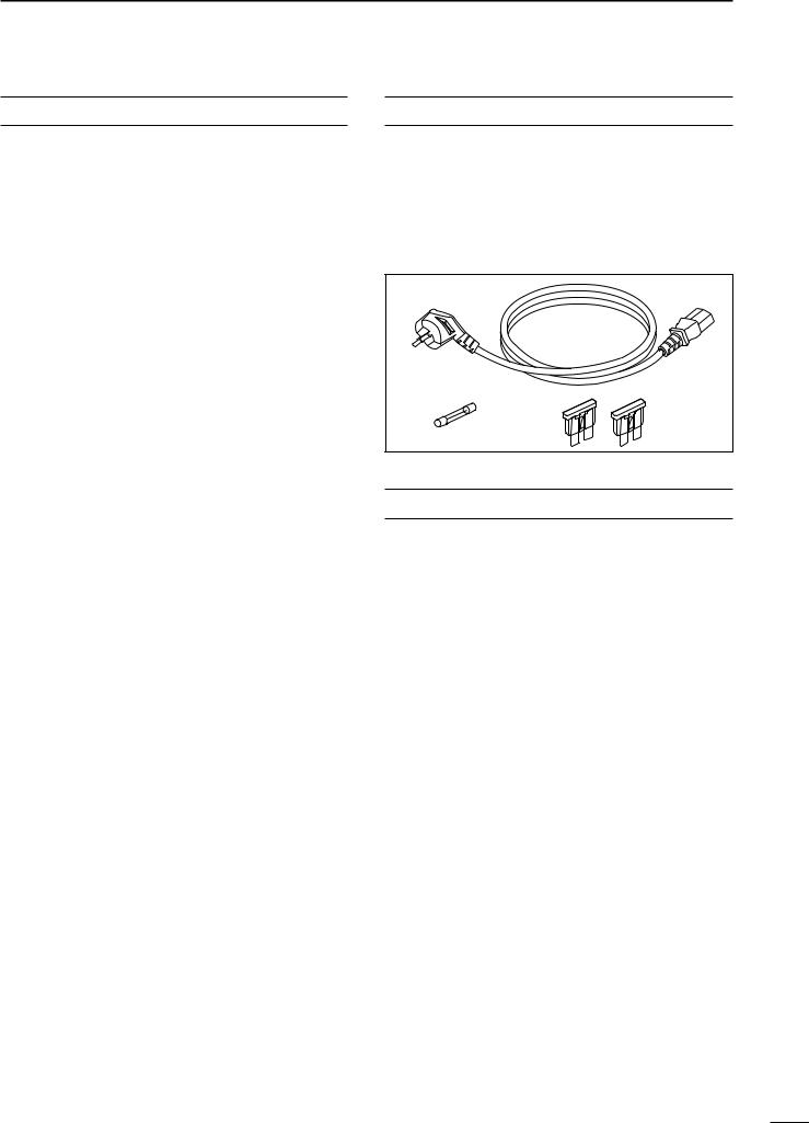
SUPPLIED ACCESSORIES
The following accessories are supplied with the ICFR3100/FR4100 series
q AC power cable (OPC-492) ……………………… 1 w Spare fuse (FGB 1 A)……………………………… 1 e Spare fuses (ATC 20)……………………………… 2
q
w |
e |
EXPLICIT DEFINITIONS |
|
|
IMPORTANT ............................................................ |
i |
|
EXPLICIT DEFINITIONS ......................................... |
i |
|
PRECAUTION ......................................................... |
i |
|
FORWARD .............................................................. |
ii |
|
SUPPLIED ACCESSORIES ................................... |
ii |
|
TABLE OF CONTENTS .......................................... |
ii |
|
1 |
PANEL DESCRIPTION ......................... |
1 – 4 |
|
■ Front panel .................................................... |
1 |
|
■ Rear panel ..................................................... |
2 |
2 |
INSTALLATION AND |
|
|
CONNECTIONS .................................. |
5 – 10 |
|
■ Unpacking ..................................................... |
5 |
|
■ Selecting a location ....................................... |
5 |
|
■ Antenna connection ....................................... |
5 |
|
■ Duplexer ........................................................ |
5 |
|
■ Grounding ...................................................... |
5 |
|
■ Required connections .................................... |
6 |
|
■ Advanced connections .................................. |
7 |
|
■ Power ............................................................ |
8 |
|
■ Mounting the repeater ................................... |
8 |
3 |
OPTIONAL UNIT INSTALLATION ........... |
11 |
|
■ Opening the repeater’s case ....................... |
11 |
|
■ Voice scrambler unit installation .................. |
11 |
4 |
OPERATION ............................................ |
12 |
|
■ Turning power ON ....................................... |
12 |
|
■ Receiving and transmitting .......................... |
12 |
5 |
MAINTENANCE ................................ |
13–14 |
|
■ Troubleshooting ........................................... |
13 |
|
■ Fuse replacement ........................................ |
14 |
6 |
SPECIFICATIONS AND OPTIONS ... |
15–16 |
|
■ Specifications .............................................. |
15 |
|
■ Options ........................................................ |
16 |
7 |
ABOUT CE ........................................ |
17–20 |
ii
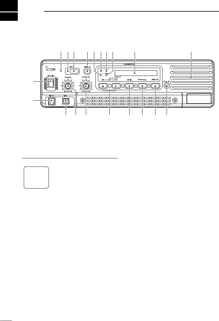
1 PANEL DESCRIPTION
■ Front panel
!9!8!7 !6!5!4!3!2 |
Function display (p. 2) |
!1 |
q
w
e r t
y u i o !0
q POWER SWITCH [POWER]
Toggle to turn the repeater power ON or OFF.
w MICROPHONE/SPEAKER CONNECTOR [MIC/SP]
This 8-pin modular jack accepts the optional microphone.
|
|
|
|
|
|
|
|
|
|
|
q +9 V DC output (Max. 10 mA) |
|
|
|
|
|
|
|
|
|
|
|
w I/O port for PC programming |
|
|
|
|
|
|
|
|
|
|
|
e NC |
|
|
|
|
|
|
|
|
|
|
|
|
|
|
|
|
|
|
|
|
|
|
|
r M PTT (Input port for TX control) |
|
q |
i |
|||||||||
|
|
|
|
|
|
|
|
|
|
|
t Microphone ground |
|
|
|
|
|
|
|
|
|
|
|
y Microphone input |
|
|
|
|
|
|
|
|
|
|
|
u Ground |
|
|
|
|
|
|
|
|
|
|
|
|
|
|
|
|
|
|
|
|
|
|
|
|
|
|
|
|
|
|
|
|
|
|
|
i M MONI (Input port for monitor control) |
|
|
|
|
|
|
|
|
|
|
|
|
e LINE CONNECTOR [LINE]
This 4-pin modular jack allows connection of a 2 wire system telephone cable.
•See p. 7 for line connector information.
r VOLUME CONTROL [VOLUME] (p. 12) Adjusts the audio output level.
t SQUELCH CONTROL [SQUELCH]
While in base operating mode, adjusts the squelch threshold level. (p. 12)
While in repeater operating mode, this knob is not activated.
y CHANNEL SELECT SWITCHES [DN/UP]
Push either switch to select the operating channel.
u MONITOR SWITCH [MONI]
Push to monitor the operating frequency.
i MODE SELECT SWITCH [RPT/BASE]
Toggles the repeater or base operating mode when pushed.
•When setting up a repeater system using ICFR3100/FR4100 only, select a repeater operating mode.
•When using IC-FR3100/FR4100 as a full (or half) duplex transceiver, or setting up a repeater system connecting an external controller, select a base operating mode.
o REMOTE CONTROL SWITCH [REMOTE]
Toggle to activate or inactivate the remote control operation when pushed.
!0AF MUTE CONTROL [SP MUTE]
Mutes the audio output.
!1INTERNAL SPEAKER
Monitors received signals.
!2BASE OPERATING MODE INDICATOR
Lights green while in base operating mode.
!3REMOTE CONTROL MODE INDICATOR
Lights green while in remote control operation mode.
!4TRANSMIT INDICATOR
Lights red while transmitting.
!5BUSY INDICATOR
Lights green while receiving a signal or when the noise squelch is open.
1

!6ANI CLEAR SWITCH [ANI CLR]
Push for 1 sec. to clear the received ANI ID indication on the display and return to the original indication.
 NOTE: This switches’ function is not available for
  some versions.
!7DEALER-PROGRAMMABLE SWITCH [PROG]
Toggles the pre-programmed function ON or OFF when pushed.
!8PROGRAMMED FUNCTION INDICATOR
Lights green while the pre-programmed function is activated.
!9DC INDICATOR
Lights green during DC operation.
PANEL DESCRIPTION |
1 |
DFunction display
32HH@HICOMHINC.
q w e |
r |
q MEMORY CHANNEL INDICATOR
Shows the selected memory channel.
w TRANSMIT POWER INDICATOR
Shows the output power level.
e AUDIBLE INDICATOR
“@” appears during audible condition, disappears during inaudible condition. (During audible condition, the audio mute is cancelled.)
r ALPHANUMERIC INDICATORS
Shows a variety of text or code information.
■ Rear panel
EXT SP |
REMOTE |
TX/TX•RX |
ACC |
q w |
e |
r |
q TRANSMIT ANTENNA CONNECTOR [TX/TX•RX]
Connects a transmit antenna (impedance: 50 Ω) and outputs transmit signals.
When installing an optional internal duplexer (supplied by a third party), this connects the transmit/receive to an antenna.
w EXTERNAL SPEAKER CONNECTOR [EXT SP]
Accepts a 4 Ω external speaker.
e REMOTE CONNECTOR [REMOTE]
Connects to the remote controller.
•See p. 3 for remote connector information.
r ACCESSORY CONNECTOR [ACC]
Connects to the remote controller.
•See pgs. 3, 4 for accessory connector information.
t RECEIVE ANTENNA CONNECTOR [RX]
Connects a receive antenna (impedance: 50 Ω) and inputs received signals.
BATTERY
AC
i
RX
GND
t y |
u |
When installing an internal duplexer (supplied by third party), do not use this connector.
y AC POWER SOCKET [AC]
Connects the supplied AC power cable to a domestic AC outlet.
u GROUND TERMINAL [GND]
Ground the repeater through this terminal to prevent electric shocks, TVI, BCI and other problems.
i DC POWER INPUT TERMINALS [BATTERY]
Connects the 12 V storage battery for the repeater backup when the AC power is interrupted. These terminals are also used for DC power operation.
 CAUTION: NEVER short the (+) line of the DC
power cable to the repeater’s chassis when con-
 necting a DC power cable to the [BATTERY] termi-
  nals. Otherwise there is danger of electric shock
  and/or equipment damage.
2
1 PANEL DESCRIPTION
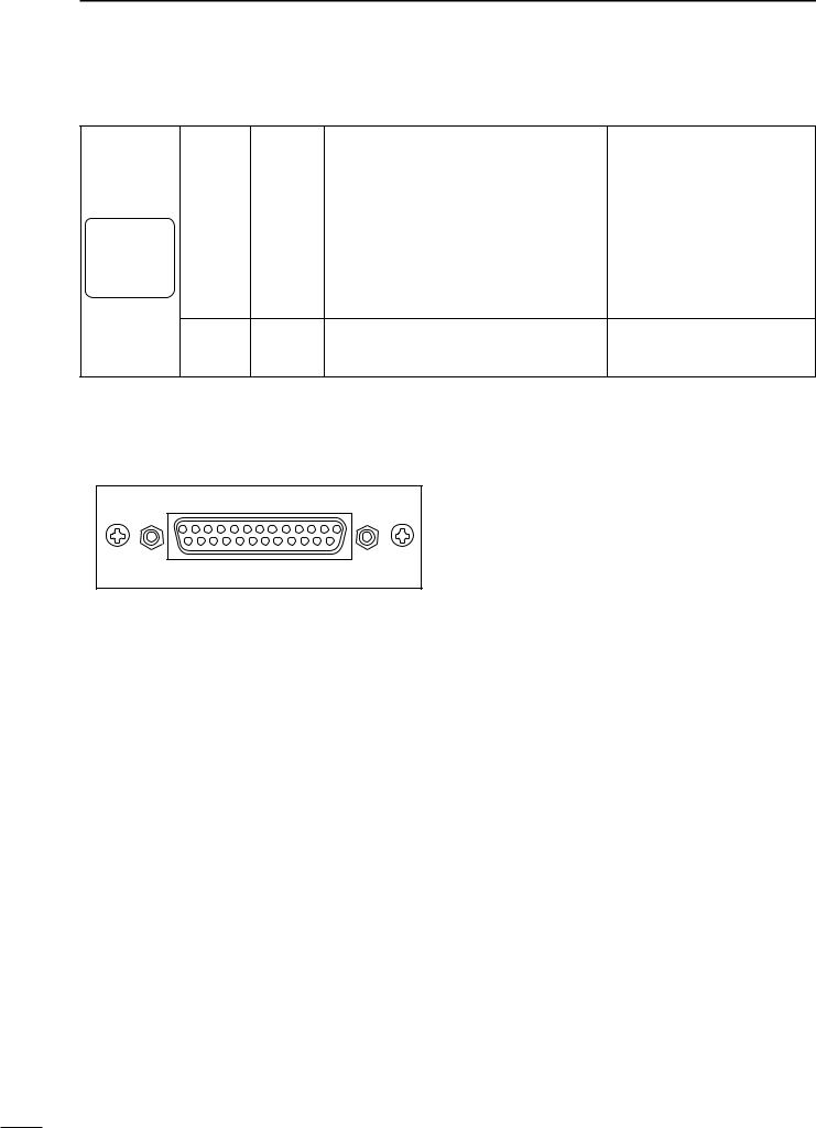
D Remote connector
|
|
|
|
|
|
|
|
|
|
|
|
|
|
Pin No. |
Pin Name |
Description |
Specification |
|
|
|
|
|
|
|
|
|
|
|
|
|
1 |
–PTT |
Input terminals to transmit the repeater in rela- |
High voltage=PTT ON (transmits) |
|
|
|
|
|
|
|
|
|
|
|
|
|
|
tion to the external equipment. An opto-isolator |
||||
|
|
|
|
|
|
|
|
|
|
|
|
|
|
|
|
||
|
|
|
|
|
|
|
|
|
|
|
|
|
2 |
|
Hi-Z=PTT OFF |
||
|
|
|
|
|
|
|
|
|
|
|
|
|
+PTT |
is provided to facilitate PTT signals. |
|||
|
|
|
|
|
|
|
|
|
|
|
|
|
|
||||
|
|
|
|
|
|
|
|
|
|
|
|
|
|
|
|
|
|
|
|
|
|
|
|
|
|
|
|
|
|
|
3 |
–AFOUT |
Output terminal for AF signals from the AF de- |
Output impedance: 600 Ω |
|
|
|
|
|
|
|
|
|
|
|
|
|
|
|
|
|
tector circuit via the bandpass filter. Output level |
|
|
|
|
|
|
|
|
|
|
|
|
|
|
4 |
+AFOUT |
|||
|
q |
|
|
|
i |
is fixed, regardless of [AF] control. |
|
||||||||||
|
|
|
|
|
|
|
|
|
|
|
|
|
|
|
|
|
|
|
|
|
|
|
|
|
|
|
|
|
|
|
5 |
–EXTMOD |
Input terminal for the modulation circuit. |
Input impedance: 600 Ω |
|
|
|
|
|
|
|
|
|
|
|
|
|
|
|
|
|
||
|
|
|
|
|
|
|
|
|
|
|
|
|
|
|
|
||
6+EXTMOD
7–BUSY Output terminal for squelch condition
|
|
(Open/Close). An opto-isolator is provided to fa- |
Open collector=BUSY OFF |
|
8 |
+BUSY |
0 V=BUSY ON (Squelch is opened) |
||
cilitate BUSY signals. |
||||
|
D Accessory connector
|
!3 |
q |
|
|
|
@5 |
!4 |
|
|
|
|
|
|
|
Pin No. |
Pin Name |
Description |
Specification |
|
1 |
BUSY OUT |
Output terminal for busy signal. |
Open collector=OFF, 0 V=ON |
|
|
|
|
|
|
2 |
COAXIAL SW |
Output terminal for coaxial switching (antenna switching) |
Open collector=OFF |
|
signal. |
0 V=ON |
|||
|
|
|||
|
|
|
|
|
3 |
M/S IN |
Input terminal for master/slave signal. |
+5 V pull up, Active=L |
|
|
|
|
|
|
4 |
D1 |
Input terminal for selecting memory channel. |
+5 V pull up, Active=L |
|
|
|
|
|
|
5 |
D3 |
Input terminal for selecting memory channel. |
+5 V pull up, Active=L |
|
|
|
|
|
|
6 |
EXT RPT/BASE |
Input terminal for repeater/base operating mode switching |
+5 V pull up |
|
signal. |
Active=L |
|||
|
|
|
|
|
7 |
EXT MONI |
Input terminal for monitor function. |
+5 V pull up, Active=L |
|
|
|
|
|
|
8 |
EXT DTCS |
Input terminal for continuous tone (CTCSS/DTCS) signal. |
Input impedance: 100 kΩ (approx.) |
|
|
|
|
|
|
9 |
EXTMOD IN B |
Input terminal for the modulation signals applied to input of |
Input impedance: 600 Ω (approx.) |
|
the splutter filter circuit. |
||||
|
|
|
|
|
10 |
EXTMOD IN A |
Input terminal for the modulation signal applied to input of |
Input impedance: 600 Ω (approx.) |
|
the pre-emphasis circuit via the bandpass filter. |
||||
|
|
|
|
|
|
|
Output terminal for AF signals from the AF detector circuit |
|
|
11 |
AF OUT |
via the bandpass filter. Output level is fixed, regardless of |
Output impedance: 1 kΩ (approx.) |
|
|
|
[AF] control. |
|
|
|
|
|
|
|
12 |
DISC OUT |
Output terminal for AF signals from the AF detector circuit. |
Output impedance: 1 kΩ (approx.) |
|
|
|
Output level is fixed, regardless of [AF] control. |
|
|
13 |
+15V |
Output terminal for +15V DC while in AC operation. (While in |
Output current: Less than 1 A |
|
|
|
DC operation, same as input DC.) |
|
|
14 |
TX OUT |
Output terminal for transmission state. |
Open collector=OFF, 0 V=ON |
|
|
|
|
|
3

PANEL DESCRIPTION |
1 |
Accessory connector (continued)
Pin No. |
Pin Name |
Description |
Specification |
|
|
|
|
15 |
M/S OUT |
Output terminal for master/slave signal. |
Open collector=OFF, 0V=ON |
|
|
|
|
16 |
D0 |
Input terminal for selecting memory channel. |
+5 V pull up, Active=L |
|
|
|
|
17 |
D2 |
Input terminal for selecting memory channel. |
+5 V pull up, Active=L |
|
|
|
|
18 |
D4 |
Input terminal for selecting memory channel. |
+5 V pull up, Active=L |
|
|
|
|
19 |
EXT PTT |
Input terminal for PTT signal. |
+5 V pull up, Active=L |
|
|
|
|
20 |
RSSI |
Output terminal for RSSI (Received Signal Strength Indica- |
Output impedance: 1 kΩ (approx.) |
|
|
tor) signal. |
|
21–24 |
AGND |
Analog ground |
|
|
|
|
|
25 |
DC GND |
Ground for +15 V DC |
|
|
|
|
|
• Pin 4, pin 5, pins 16–18 select one of the 32 pre-programmed memory channels. (see table below) [0]: Hi-Z, [1]: 0 V (D0–D4: +5 V pull up)
Channel |
D4 |
D3 |
D2 |
D1 |
D0 |
Channel |
D4 |
D3 |
D2 |
D1 |
D0 |
|
(pin 18) |
(pin 5) |
(pin 17) |
(pin 4) |
(pin16) |
(pin 18) |
(pin 5) |
(pin 17) |
(pin 4) |
(pin16) |
|||
|
|
|||||||||||
|
|
|
|
|
|
|
|
|
|
|
|
|
1 |
0 |
0 |
0 |
0 |
0 |
17 |
1 |
0 |
0 |
0 |
0 |
|
|
|
|
|
|
|
|
|
|
|
|
|
|
2 |
0 |
0 |
0 |
0 |
1 |
18 |
1 |
0 |
0 |
0 |
1 |
|
|
|
|
|
|
|
|
|
|
|
|
|
|
3 |
0 |
0 |
0 |
1 |
0 |
19 |
1 |
0 |
0 |
1 |
0 |
|
|
|
|
|
|
|
|
|
|
|
|
|
|
4 |
0 |
0 |
0 |
1 |
1 |
20 |
1 |
0 |
0 |
1 |
1 |
|
|
|
|
|
|
|
|
|
|
|
|
|
|
5 |
0 |
0 |
1 |
0 |
0 |
21 |
1 |
0 |
1 |
0 |
0 |
|
|
|
|
|
|
|
|
|
|
|
|
|
|
6 |
0 |
0 |
1 |
0 |
1 |
22 |
1 |
0 |
1 |
0 |
1 |
|
|
|
|
|
|
|
|
|
|
|
|
|
|
7 |
0 |
0 |
1 |
1 |
0 |
23 |
1 |
0 |
1 |
1 |
0 |
|
|
|
|
|
|
|
|
|
|
|
|
|
|
8 |
0 |
0 |
1 |
1 |
1 |
24 |
1 |
0 |
1 |
1 |
1 |
|
|
|
|
|
|
|
|
|
|
|
|
|
|
9 |
0 |
1 |
0 |
0 |
0 |
25 |
1 |
1 |
0 |
0 |
0 |
|
|
|
|
|
|
|
|
|
|
|
|
|
|
10 |
0 |
1 |
0 |
0 |
1 |
26 |
1 |
1 |
0 |
0 |
1 |
|
|
|
|
|
|
|
|
|
|
|
|
|
|
11 |
0 |
1 |
0 |
1 |
0 |
27 |
1 |
1 |
0 |
1 |
0 |
|
|
|
|
|
|
|
|
|
|
|
|
|
|
12 |
0 |
1 |
0 |
1 |
1 |
28 |
1 |
1 |
0 |
1 |
1 |
|
|
|
|
|
|
|
|
|
|
|
|
|
|
13 |
0 |
1 |
1 |
0 |
0 |
29 |
1 |
1 |
1 |
0 |
0 |
|
|
|
|
|
|
|
|
|
|
|
|
|
|
14 |
0 |
1 |
1 |
0 |
1 |
30 |
1 |
1 |
1 |
0 |
1 |
|
|
|
|
|
|
|
|
|
|
|
|
|
|
15 |
0 |
1 |
1 |
1 |
0 |
31 |
1 |
1 |
1 |
1 |
0 |
|
|
|
|
|
|
|
|
|
|
|
|
|
|
16 |
0 |
1 |
1 |
1 |
1 |
32 |
1 |
1 |
1 |
1 |
1 |
|
|
|
|
|
|
|
|
|
|
|
|
|
4
2 INSTALLATION AND CONNECTIONS
■ Unpacking |
■ Duplexer |
After unpacking, immediately report any damage to the delivering carrier or dealer. Keep the shipping cartons.
For a description and a diagram of accessory equipment included with the IC-FR3100/FR4100 series, see ‘Supplied Accessories’ on p. ii of this manual.
A duplexer is separately required when only one antenna is used for both transmitting and receiving. Select a duplexer according to the transmitting and receiving frequencies. Ask your Dealer for details.
■ Selecting a location
Select a location for the repeater that allows adequate air circulation, free from extreme heat, cold, or vibrations, and away from TV sets, TV antenna elements, radios and other electromagnetic sources.
■ Antenna connection
For radio communications, the antenna is of critical importance, along with output power and sensitivity. Selecting antenna(s), such as a well-matched 50 Ω antenna, and feedline. 1.5:1 or better of Voltage Standing Wave Ratio (VSWR) is recommended for the desired band. Of course, the transmission line should be a coaxial cable.
 CAUTION: Protect the repeater from lightning by
 using a lightning arrestor.
 NOTE: There are many publications covering
 proper antennas and their installation. Check with
 your local dealer for more information and recom-
  mendations.
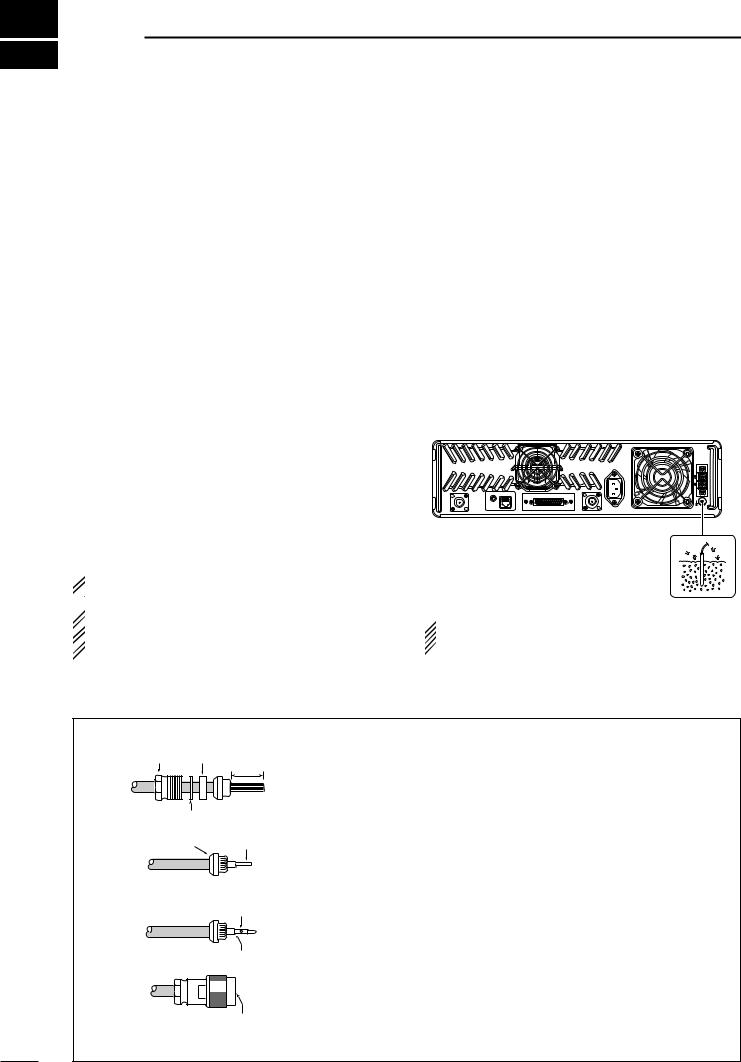
■ Grounding
To prevent electrical shock, television interference (TVI), broadcast interference (BCI) and other problems, ground the transceiver through the [GND] terminal on the rear panel.
For best results, connect a heavy gauge wire or strap to a long earth-sunk copper rod. Make the distance between the [GND] terminal and ground as short as possible.
BATTERY
AC
EXT SP REMOTE |
ACC |
RX |
TX/TX•RX |
|
GND
 RWARNING: NEVER connect the [GND] termi-
nal to a gas or electric pipe, since the connection  could cause an explosion or electric shock.
TYPE-N CONNECTOR INSTALLATION EXAMPLE
q
w
Nut Rubber gasket
15 mm
Washer
Center Clamp conductor
3 mm 


 6 mm
6 mm
Slide the nut, flat washer, rubber gasket and clamp over the coaxial cable, then cut the end of the cable evenly.
Strip the cable and fold the braid back over the clamp.
e
r
Solder hole
No space
Be sure the center conductor is the same height as the plug body.
Soft solder the center conductor. Install the center conductor pin and solder it.
Carefully slide the plug body into place aligning the center conductor pin on the cable. Tighten the nut onto the plug body.
30 mm ≈ 9⁄8 in 10 mm ≈ 3⁄8 in 1–2 mm ≈ 1⁄16 in
5
 Loading...