


INSTRUCTION MANUAL
COMMUNICATIONS RECEIVER
iR20
This device complies with Part 15 of the FCC rules. Operation is subject to the following two conditions: (1) This device may not cause harmful interference, and (2) this device must accept any interference received, including interference that may cause undesired operation.
WARNING: MODIFICATION OF THIS DEVICE TO RECEIVE CELLULAR RADIO TELEPHONE SERVICE SIGNALS IS PROHIBITED UNDER FCC RULES AND FEDERAL LAW.
FOREWORD
Thank you for purchasing this Icom product. The IC-R20 COM- MUNICATIONS RECEIVER is designed and built with Icom’s superior technology and craftsmanship. With proper care, this product should provide you with years of trouble-free operation.
We want to take a couple of moments of your time to thank you for making your IC-R20 your radio of choice, and hope you agree with Icom’s philosophy of “technology first.” Many hours of research and development went into the design of your IC-R20.
DFEATURES
Covers 0.150–3304.999 MHz* wide
frequency range
*Some frequency bands are inhibited according to version
External power supply operation
1250 memory channels* with 26 banks
available
*200 auto write and 50 scan edge channels are included.
Built-in bar-antenna
Dualwatch operation
IMPORTANT
READ ALL INSTRUCTIONS carefully and completely before using the receiver.
SAVE THIS INSTRUCTION MANUAL— This instruction manual contains important operating instructions for the IC-R20.
EXPLICIT DEFINITIONS
WORD |
DEFINITION |
Personal injury, fire hazard or electric shock R WARNING! may occur.
CAUTION Equipment damage may occur. |
||
NOTE |
Recommended for optimum use. No risk of |
|
personal injury, fire or electric shock. |
||
|
||
Versions of the IC-R20 which display the “CE” symbol on the serial number seal, comply with the essential requirements of the European Radio and Telecommunication Terminal Directive 1999/5/EC, and that any applicable Essential Test Suite measurements have been performed.
Icom, Icom Inc. and the 
 logo are registered trademarks of Icom Incorporated (Japan) in the United States, the United Kingdom, Germany, France, Spain, Russia and/or other countries.
i

PRECAUTION
RWARNING! NEVER operate the receiver with an earphone, headphones or other audio accessories at high volume levels. Hearing experts advise against continuous high volume operation. If you experience a ringing in your ears, reduce the volume level or discontinue use.
RWARNING! NEVER connect the receiver directly to an AC outlet. This may pose a fire hazard or result in an electric shock.
RWARNING! NEVER operate the receiver while driving a vehicle. Safety driving requires your full attention—any- thing less may result in an accident.
RWARNING! NEVER throw a battery cell or battery pack into a fire since as internal battery gas can cause an explosion.
RWARNING! NEVER disassemble the battery pack. If the battery cell’s internal material (electrolyte liquid) gets into your eyes, wash your eyes with water and obtain treatment from an eye doctor immediately.
NEVER connect the receiver directly to a power source of more than 6 V DC. This will damage the receiver.
NEVER connect the receiver to a power source using reverse polarity. This will damage the receiver.
NEVER expose the receiver to rain, snow or any liquids. The receiver may be damaged.
NEVER operate or touch the receiver with wet hands. This may result in an electric shock or damage the receiver.
NEVER solder the battery cell. This may damage the battery.
AVOID using or placing the receiver in direct sunlight or in areas with temperatures below –10°C (+14˚F) or above +60°C (+140˚F).
AVOID the use of chemical agents such as benzine or alcohol in cleaning, as they can damage the receiver’s surfaces.
Even when the receiver power is OFF, a slight current still flows in the circuits. Remove the battery pack or batteries from the receiver while not using it for a long time. Otherwise, the installed battery pack or batteries will become exhausted, and will need to be recharged.
RESPECT other people’s privacy. Information overheard but not intended for you cannot lawfully be used in any way.
For U.S.A. only
CAUTION: Changes or modifications to this device, not expressly approved by Icom Inc., could void your authority to
operate this device under FCC regulations.
ii
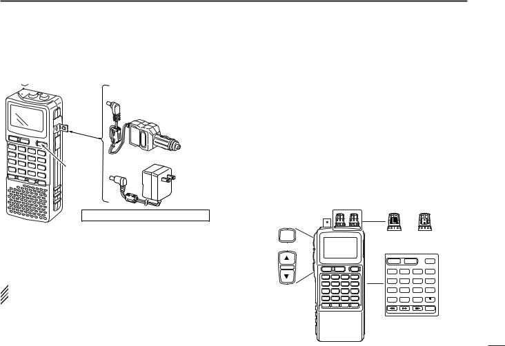
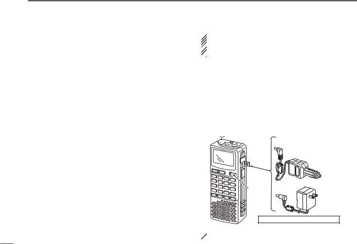
SUPPLIED ACCESSORIES
q w |
|
|
|
e |
|
r |
||||||||||
|
|
|
|
|
|
|
|
|
|
|
|
|
|
|
|
|
|
|
|
|
|
|
|
|
|
|
|
|
|
|
|
|
|
|
|
|
|
|
|
|
|
|
|
|
|
|
|
|
|
|
|
|
|
|
|
|
|
|
|
|
|
|
|
|
|
|
|
|
|
|
|
|
|
|
|
|
|
|
|
|
|
|
|
|
|
|
|
|
|
|
|
|
|
|
|
|
|
|
|
|
|
|
|
|
|
|
|
|
|
|
|
|
|
|
|
|
|
|
ty
qAntenna ………………………………………………………1
wBelt clip (MB-98)…………………………………………1 set eBattery spacer ………………………………………………1
rHand strap …………………………………………………1
tBattery pack* (BP-206) ……………………………………1
yAC adaptor*(BC-149A/D) …………………………………1
(The shape of the BC-149A and BC-149D are different.) *Not supplied with some versions.
OPERATING THEORY
Electromagnetic radiation which has frequencies of 20,000 Hz (20 kHz*) and above is called radio frequency (RF) energy because it is useful in radio transmissions. The ICR20 receives RF energy from 0.150 MHz* to 3304.999 MHz and converts it into audio frequency (AF) energy which in turn actuates a loudspeaker to create sound waves. AF energy is in the range of 20 to 20,000 Hz.
*kHz is an abbreviation of kilohertz or 1000 hertz, MHz is abbreviation of megahertz or 1,000,000 hertz, where hertz is a unit of frequency.
OPERATING NOTES
The IC-R20 may receive its own oscillated frequency, resulting in no reception or only noise reception, on some frequencies.
The IC-R20 may receive interference from extremely strong signals on different frequencies or when using an external high-gain antenna.
iii

TABLE OF CONTENTS
FOREWORD ................................................... |
i |
|
IMPORTANT ................................................... |
i |
|
EXPLICIT DEFINITIONS ................................ |
i |
|
PRECAUTION ................................................ |
ii |
|
SUPPLIED ACCESSORIES .......................... |
iii |
|
OPERATING THEORY .................................. |
iii |
|
OPERATING NOTES .................................... |
iii |
|
TABLE OF CONTENTS ................................ |
iv |
|
QUICK REFERENCE GUIDE ................. |
I–VIII |
|
|
■ Preparations ............................................ |
I |
|
■ Your first scanning experience .............. |
IV |
|
■ Memory programming........................... |
VI |
|
■ Programmed scan operation................ |
VII |
1 |
PANEL DESCRIPTION ......................... |
1–7 |
|
■ Front, top and side panels ..................... |
1 |
|
■ Function display ..................................... |
6 |
2 |
BATTERY INSTALLATION/CHARGING ... |
8–10 |
|
■ Battery installation .................................. |
8 |
|
■ Caution ................................................... |
9 |
|
■ Battery charging ..................................... |
9 |
3 FREQUENCY AND CHANNEL SETTING |
||
|
.......................................................... |
11–16 |
|
■ Mode selection...................................... |
11 |
|
■ Operating band selection ..................... |
12 |
|
■ Setting a tuning step............................. |
14 |
|
■ Setting a frequency .............................. |
14 |
|
■ Receive mode selection ....................... |
16 |
|
■ Lock function ........................................ |
16 |
4 |
BASIC OPERATION ......................... |
17–23 |
|
■ Receiving.............................................. |
17 |
|
■ Setting audio volume............................ |
17 |
|
■ Squelch level setting ............................ |
18 |
|
■ Monitor function.................................... |
18 |
|
■ Attenuator function ............................... |
19 |
|
■ RF gain................................................. |
19 |
|
■ Duplex operation .................................. |
20 |
|
■ AFC function......................................... |
21 |
|
■ NB/ANL functions ................................. |
21 |
|
■ Band scope .......................................... |
22 |
|
■ [DIAL] function assignment .................. |
23 |
5 |
DUALWATCH OPERATION ............. |
24–25 |
|
■ Main band selection ............................. |
24 |
|
■ Band exchange .................................... |
24 |
|
■ Setting audio volume............................ |
25 |
|
■ Squelch level setting ............................ |
25 |
6 |
MEMORY CHANNELS ...................... |
26–33 |
|
■ General description .............................. |
26 |
|
■ Memory channel programming............. |
26 |
|
■ Memory bank setting ............................ |
27 |
|
■ Memory bank selection ........................ |
28 |
|
■ Programming memory/bank name ....... |
29 |
|
■ Selecting memory/bank name indication..... 30 |
|
|
■ Copying memory contents.................... |
31 |
|
■ Memory clearing................................... |
32 |
|
■ Erasing/transferring bank contents....... |
33 |
7 |
SCAN OPERATION .......................... |
34–41 |
|
■ Scan types............................................ |
34 |
|
■ Full/band/programmed scan................. |
35 |
|
■ Scan edges programming .................... |
36 |
|
■ Memory/bank/all bank scan.................. |
37 |
|
■ Auto-memory write scan....................... |
38 |
|
■ Skip channel/frequency setting ............ |
39 |
|
■ Scan resume condition......................... |
40 |
8 |
PRIORITY WATCH ........................... |
42–44 |
|
■ Priority watch types .............................. |
42 |
|
■ Priority watch operation........................ |
43 |
9 |
COMFORTABLE RECEIVING........... |
45–48 |
|
■ Tone/DTCS squelch operation ............. |
45 |
■ Tone squelch frequency/DTCS code set-
ting........................................................ |
46 |
■ DTCS polarity setting ........................... |
47 |
■ Tone scan ............................................. |
48 |
10 SET MODE ....................................... |
49–59 |
■ General................................................. |
49 |
■ Set mode items .................................... |
50 |
11 OTHER FUNCTIONS ........................ |
60–67 |
■ Antenna selection................................. |
60 |
■ Weather channel operation .................. |
61 |
■ Data cloning ......................................... |
62 |
■ Auto power-off function......................... |
63 |
■ IC recorder ........................................... |
64 |
■ Partial reset .......................................... |
67 |
■ All reset ................................................ |
68 |
12 CONTROL COMMAND .................... |
68–69 |
■ General................................................. |
68 |
■ Data format........................................... |
68 |
■ Command table .................................... |
68 |
13 FREQUENCY TABLE ....................... |
70–77 |
■ TV channels ......................................... |
70 |
■ VHF marine channels........................... |
73 |
■ Weather channels................................. |
73 |
■ Other communications in the USA ....... |
74 |
■ Other communications—other countries .... 76 |
|
14 MAINTENANCE ...................................... |
78 |
■ Troubleshooting.................................... |
78 |
15 SPECIFICATIONS .................................. |
79 |
16 OPTIONS ................................................ |
80 |
17 DRIVER INSTALLATION ........................ |
81 |
18 POCKET GUIDE ..................................... |
92 |
19 CE ........................................................... |
94 |
1
2
3
4
5
6
7
8
9
10
11
12
13
14
15
16
17
18
19
iv

QUICK REFERENCE GUIDE
■ Preparations
D Batteries installation
qRemove the battery cover from the receiver.
wFor alkaline battery use, attach the supplied battery spacer.
|
w |
q |
e |
|
D Battery pack installation
q Remove the battery cover from the receiver.
w Remove the supplied battery spacer for R6 (AA) size battery use.
eInstall the Li-Ion battery pack (BP-206).
•Be sure to observe the correct direction.
•Charge Li-Ion battery pack (BP-206) before use. (Refer to p. IV for charging instructions.)
•Battery pack installation |
•Battery pack removal |
eInstall 3 R6 (AA) size alkaline batteries.
• Be sure to observe the correct polarity.
 Keep the battery contacts clean to avoid rust or poor contact.
  It’s a good idea to clean the battery terminals once a week.
I
D Handstrap
Slide the handstrap through the loop on the top of the rear panel as illustrated at below. Facilitates carrying.
D Belt clip
Conveniently attaches to your belt.
Attach the belt clip with the supplied screws using a phillips screwdriver.
D Swivel belt clip (Option)
The optional swivel belt clip (MB-86) is useful for easy attaching/detaching the receiver to/from the belt.
qAttach the stopper with the supplied screws using a phillips screwdriver.
QUICK REFERENCE GUIDE
w Clip the belt clip to your belt.
e Insert the receiver into the end of the clip as shown at right.
• Once the receiver is locked in place, it will swivel 360 degrees.
Quick reference guide
II
QUICK REFERENCE GUIDE
To remove:
rTurn the receiver upside down, and then lift to release the receiver from the belt clip as shown at upper right.
D Antenna
Insert the supplied antenna into the antenna connector and screw down the antenna as shown at right.
NEVER hold the antenna when carrying the receiver.
 For your information
Third-party antennas may in-  crease receiver performance.
III
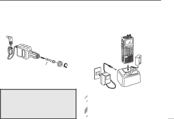
D Charging the battery
 IC-R20
to [DC] jack
Turn power
 OFF.
OFF.
Optional CP-18A/E Cigarette lighter cable with DC-DC converter
to cigarette lighter socket
AC adaptor
BC-149A/D
to AC outlet
Charging periods: 8 hours (w/BP-206)
qInstall the battery pack (BP-206).
wPlug the AC adaptor into an AC outlet.
eTurn OFF the receiver, then insert the adaptor plug into the [DC] jack of the receiver.
 RWARNING!:
NEVER attempt to charge any other batteries. Because  the IC-R20 can charge the BP-206 only.
Keep the jack cover attached when jack is not in use to protect the connectors from dust and moisture.
QUICK REFERENCE GUIDE
■ Your first scanning |
|
|
guide |
||
experience |
||
|
||
Now that you have your IC-R20 ready, you are probably ex- |
reference |
|
cited to start listening. We would like to take you through a |
||
|
||
few basic operation steps to make your first “Scanning Expe- |
|
|
rience” enjoyable. |
Quick |
|
D About default setting |
||
|
||
The frequency control ([R-DIAL]) function can be traded with |
|
|
volume control ([L-DIAL] and [Y]/[Z] keys) function by push- |
|
|
ing for 1 sec. [1 DIAL.SEL]. However, in this QUICK REF- |
|
|
ERENCE GUIDE, the factory default setting ([R-DIAL] sets |
|
|
operating frequency) is used for simple instruction. |
|
SQL |
|
Top |
|
|
|
|
|
|
|
|
DUALWATCH |
MAIN/SUB |
POWER |
|
|
BAND |
VFO |
MODE |
MR |
|
MHz |
SCAN |
S.MW |
|
|
1 |
2 |
3 |
SCOPE |
Left |
4 |
5 |
6 |
0AFC |
|
|
|
|
|
|
7 |
8 |
9 |
LOCK |
 REC
REC
Front
IV
QUICK REFERENCE GUIDE
D Basic operation
1. Turning ON the receiver
Push [POWER] for 1 sec. to turn the power ON.
 -DUP TSQL AFC MODE FM ANL
146 010
PSKIP
√
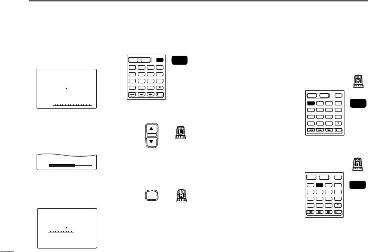
2. Adjusting audio level
Rotate [L-DIAL] (or push [Y]/ [Z]) to set the desired audio level.
√
VOL
3. Adjusting squelch level
While pushing [SQL], rotate [R- DIAL] to set the squelch level.
 -DUP TSQL AFC MODE
  FM ANL
146 010
PSKIP
√
SQUELCH:LEVEL9
DUALWATCH |
MAIN/SUB |
POWER |
|
BAND |
VFO |
MODE |
MR |
MHz |
SCAN |
S.MW |
|
1 |
2 |
3 |
SCOPE |
4 |
5 |
6 |
0AFC |
7 |
8 |
9 |
LOCK |
|
|
|
REC |
Left
SQL
Left
POWER
Front
Top
Top
4. Tune the desired frequency
The tuning dial will allow you to dial in the frequency you want to operate. Pages 9 and 15 will instruct you on how to set the tuning speed.
[Using the tuning dial]
qPush [BAND] several times to select the desired frequency band.
•While pushing [BAND], rotate [R-DIAL] also select frequency band.
wRotate [R-DIAL] to set the desired receive frequency.
•Push [VFO MHz] for 1 sec. then rotate [R-DIAL] to change the frequency in 1 MHz steps, or push for 1 sec. again then rotate [R-DIAL] to change the frequency in 10 MHz steps. (Each push for 1 sec. toggles 1 MHz or 10 MHz tuning steps.)
|
|
|
|
Top |
DUALWATCH |
MAIN/SUB |
POWER |
|
|
BAND |
VFO |
MODE |
MR |
BAND |
|
MHz |
SCAN |
S.MW |
|
1 |
2 |
3 |
SCOPE |
|
4 |
5 |
6 |
0AFC |
|
7 |
8 |
9 |
LOCK |
|
|
|
|
REC |
Front |
|
|
|
|
|
|
|
|
|
Top |
DUALWATCH |
MAIN/SUB |
POWER |
|
|
BAND |
VFO |
MODE |
MR |
VFO |
MHz |
SCAN |
S.MW |
MHz |
|
|
|
|
|
|
1 |
2 |
3 |
SCOPE |
|
4 |
5 |
6 |
0AFC |
|
7 |
8 |
9 |
LOCK |
|
|
|
|
REC |
Front |
|
|
|
|
|
V
[Using the keypad]
Enter the desired frequency via the keypad.
•Direct input can be set until 1 kHz digit, rotate [R-DIAL] to set below 1 kHz frequency after set tuning steps, if necessary. (See p. 14 for setting the tuning step.)
•Pushing [VFO MHz] omits the entry of 100 kHz and below, when you want to edit to these digits “0.”
•Push [DUALWATCH] to cancel the entry.
DUALWATCH |
MAIN/SUB |
POWER |
|
VFO |
|
|
|
|
|
|
|
|
MHz |
|
|
BAND |
VFO |
MODE |
MR |
1 |
2 |
3 |
|
MHz |
SCAN |
S.MW |
|
||||
|
|
|
|
|
|||
1 |
2 |
3 |
SCOPE |
|
|
|
|
4 |
5 |
6 |
0AFC |
4 |
5 |
6 |
0AFC |
7 |
8 |
9 |
LOCK |
|
|
|
|
|
|
|
REC |
7 |
8 |
9 |
LOCK |
Front
5. Receive mode selection
Push [MODE SCAN] several
times to select the desired re- |
DUALWATCH |
MAIN/SUB |
POWER |
|
||
|
VFO |
MODE |
MR |
MODE |
||
ceive mode. |
BAND |
|||||
MHz |
SCAN |
S.MW |
SCAN |
|||
|
|
|
|
|||
1 |
2 |
3 |
SCOPE |
|
||
• FM, WFM, AM, LSB, USB and |
|
|||||
4 |
5 |
6 |
0AFC |
|
||
CW are available. |
|
|||||
7 |
8 |
9 |
|
|
||
|
LOCK |
|
||||
|
|
|
|
REC |
Front |
|
|
|
|
|
|
||
QUICK REFERENCE GUIDE
■ Memory programming
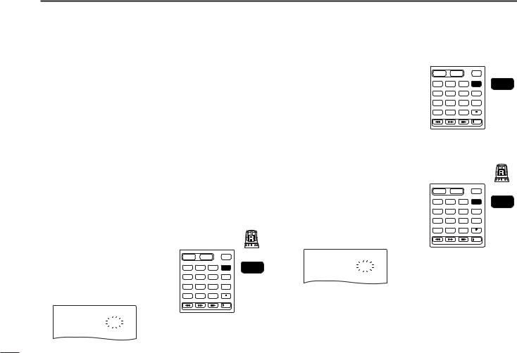
The IC-R20 has a total of 1250 memory channels (including 200 auto write channels and 50 scan edges) for storing often used receive frequency, mode, etc.
1. Setting frequency
In VFO mode, set the desired receive frequency mode.
•When “µ ” indicator is displayed, push [VFO MHz] to select the VFO mode.
2.Selecting a memory channel
Push [MR S.MW] for 1 sec., then rotate [R-DIAL] to select the desired memory channel.
Top 
DUALWATCH |
MAIN/SUB |
POWER |
• “µ ” indicator blinks.
FM
146.010 999
. µ
-BANK-:----
-BNAME:
-MNAME: -SKIP-:OFF >CLEAR
BAND |
VFO |
MODE |
MR |
MR |
MHz |
SCAN |
S.MW |
S.MW |
|
|
|
|
|
|
1 |
2 |
3 |
SCOPE |
|
4 |
5 |
6 |
0AFC |
|
7 |
8 |
9 |
LOCK |
|
|
|
|
REC |
Front |
|
|
|
|
3. Writing a memory channel
Push [MR S.MW] for 1 sec. until 3 beeps sound.
•Memory channel number automatically increases when continuing to push [MR S.MW] after programming.
Quick reference guide
VI
QUICK REFERENCE GUIDE
■ Programmed scan operation
25 pairs, 50 channels of memories are used for programmed scan operation, that specify a scanning range. The programmed scan scans between “xxA” and “xxB” (xx=00 to 24) frequencies. Therefore, before operating the programmed scan, different frequencies must be programmed into “A” and “B” channels.
D Programming scan edges
A start frequency must be programmed into a “xxA,” and end frequency must be programmed into a “xxB” memory channel.
1. Setting frequency
In VFO mode, set the desired receive frequency mode.
•When “µ ” indicator is displayed, push [VFO MHz] to select the VFO mode.
2.Selecting a scan edge channel “A”
Push [MR S.MW] for 1 sec., then rotate [R-DIAL] to select one of the desired scan edge channel “A.”
• “µ ” indicator blinks.
FM
146.010 03A
. µ
-BANK-:----
-BNAME:
|
|
|
Top |
|
DUALWATCH |
MAIN/SUB |
POWER |
|
|
BAND |
VFO |
MODE |
MR |
MR |
MHz |
SCAN |
S.MW |
S.MW |
|
|
|
|
|
|
1 |
2 |
3 |
SCOPE |
|
4 |
5 |
6 |
0AFC |
|
7 |
8 |
9 |
LOCK |
|
REC
Front
3. Writing a memory channel
Push [MR S.MW] for 1 sec. until 3 beeps sound.
•Scan edge channel “B” is automatically selected when continuing to push [MR S.MW] after programming.
•After programming is completed, return to VFO indication.
4.Selecting a scan edge channel “B”
Push [MR S.MW] for 1 sec., then rotate [R-DIAL] to select one of the desired scan edge channel “B.”
•“µ ” indicator blinks.
•When the scan edge channel “B” is already selected at step 3. (continuing to push [MR S.MW] after programming), skip this step.
FM
146.010 03B
. µ
-BANK-:----
-BNAME:
DUALWATCH |
MAIN/SUB |
POWER |
|
|
BAND |
VFO |
MODE |
MR |
MR |
MHz |
SCAN |
S.MW |
S.MW |
|
|
|
|
|
|
1 |
2 |
3 |
SCOPE |
|
4 |
5 |
6 |
0AFC |
|
7 |
8 |
9 |
LOCK |
|
|
|
|
REC |
Front |
|
|
|
|
|
|
|
|
Top |
|
DUALWATCH |
MAIN/SUB |
POWER |
|
|
BAND |
VFO |
MODE |
MR |
MR |
MHz |
SCAN |
S.MW |
S.MW |
|
|
|
|
|
|
1 |
2 |
3 |
SCOPE |
|
4 |
5 |
6 |
0AFC |
|
7 |
8 |
9 |
LOCK |
|
|
|
|
REC |
Front |
|
|
|
|
|
5. Writing a memory channel
Push [MR S.MW] for 1 sec. until 3 beeps sound.
•The next scan edge channel “A” is automatically selected when continuing to push [MR S.MW] after programming.
•After programming is completed, return to VFO indication.
VII
D Starting scan
1. Select VFO mode.
Push [VFO MHz] to select the VFO mode for full, band and programmed scan operation.
•Select memory mode by pushing [MR S.MW] for memory or bank scan.
2. Selecting a scanning type
While pushing and holding
[MODE SCAN], rotate [R-DIAL] to select one of the desired scanning type.
•Available scan types when VFO mode is selected; “ALL” for full scan; “BAND” for the selected band; one of “PROGxx” (xx=0 to 24) for programmed scan.
•Available scan types when memory bank is selected; “ALL” for all memory scan, “BANK-LINK” for banklink scan; “BANK” for the selected bank scan.
|
|
|
Top |
|
DUALWATCH |
MAIN/SUB |
POWER |
|
|
BAND |
VFO |
MODE |
MR |
MODE |
MHz |
SCAN |
S.MW |
SCAN |
|
|
|
|
|
|
1 |
2 |
3 |
SCOPE |
|
4 |
5 |
6 |
0AFC |
|
7 |
8 |
9 |
LOCK |
|
REC
Front
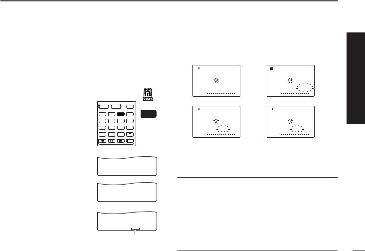
• Full scan
PSKIP
√
SCAN:ALL
• Band scan
PSKIP
√
SCAN:BAND
• Programmed scan
PSKIP
√
SCAN:PROG-01
Selectable between “00” to “24” if programmed
QUICK REFERENCE GUIDE
3. Starting scan
Release [MODE SCAN] to start the scan.
• Rotate [R-DIAL] to change the scanning direction.
• During full/band scan |
• During programmed scan |
||||||||||
|
|
-DUP TSQL |
AFC |
|
|
-DUP TSQL |
AFC |
||||
|
|
|
|
||||||||
MODE FM ANL |
|
|
MODE FM ANL |
|
|
||||||
|
|
1480 888000 |
|
|
|
1480 888000 |
|
||||
|
|
|
|
PSKIP |
|
|
|
|
PSKIP |
||
|
√ |
|
|
|
|
|
√ |
|
|
P01 |
|
|
|
|
|
|
|
|
|
||||
• During memory/all/bank scan • During bank scan |
|||||||||||
|
|
-DUP TSQL |
AFC |
|
|
-DUP TSQL |
AFC |
||||
|
|
|
|
||||||||
MODE FM ANL |
|
|
MODE FMFM ANL |
|
|
||||||
|
|
888000 888000 |
|
|
|
888000 888000 |
|
||||
|
|
|
|
PSKIP |
|
|
|
|
PSKIP |
||
|
√ |
µ |
012 |
|
|
√ |
µ |
P01 |
|||
|
|
|
|
|
|
|
|
|
|
|
|
4. Cancelling scan
Push [DUALWATCH] to stop the scan.
For your information
The memory channel number you program the scan edges into correlate “PROGxx” as follows:
PSKIP
00A/00B: Scans between frequencies programmed in 00A
√
and SCAN:ALL00B channels, and select “PROG-00” 01A/01B: Scans between frequencies programmed in 01A
and 01B channels, and select “PROG-01” |
||
|
PSKIP |
|
√ |
• |
|
SCAN:BAND |
||
• |
||
|
• |
|
24A/24B: Scans between frequencies programmed in 24A
PSKIP
and √24B channels, and select “PROG-24”
Quick reference guide
VIII
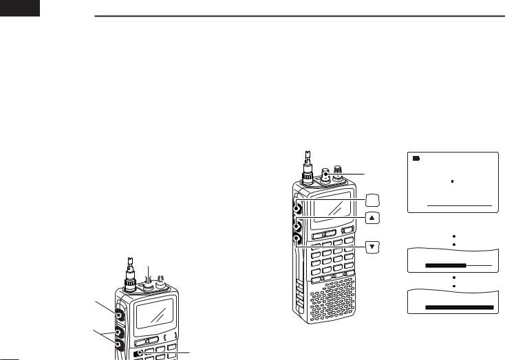
 1 PANEL DESCRIPTION
■ Front, top and side panels
|
i |
|
u |
q |
|
w |
y |
|
t |
|
r |
e


 KEYPAD
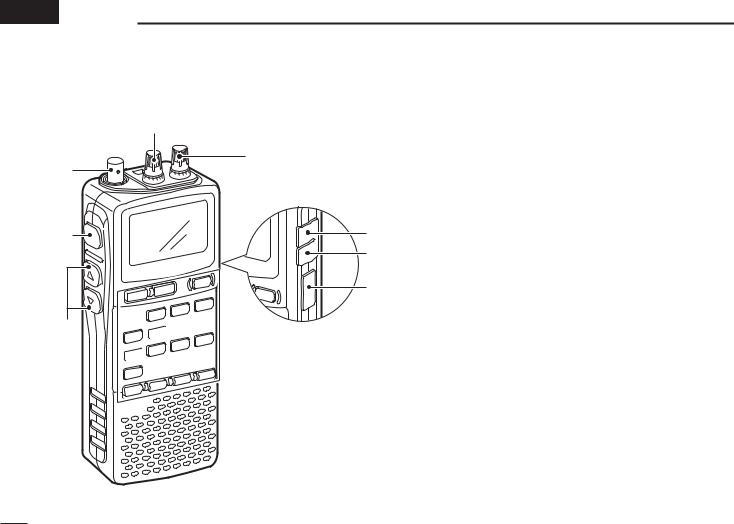
qANTENNA CONNECTOR (p. II)
BNC connector: Connects the supplied antenna.
wSQUELCH KEY [SQL] (p. 18)
Push and hold to temporarily open the squelch and monitor the operating frequency.
While pushing this key, rotate the tuning dial* to adjust the squelch level.
eUP/DOWN KEYS [Y]/[Z]
Adjust audio volume level.* (p. 17)
rUSB JACK [USB]
Connects to a PC using an optional OPC-1382 CLONING CABLE for cloning. Cloning allows you to quickly and easily transfer the programmed contents between the IC-R20 and the connected PC.
tEXTERNAL DC-IN CONNECTOR [DC] (p. 9)
Connects an AC adaptor or an optional cigarette lighter cable for both charging the installed re-chargeable battery pack and operating.
yEXTERNAL SPEAKER CONNECTOR [SP/CI-V]
Connect an optional earphone or headphone.
The internal speaker will not function when any external equipment is connected. (See p. 80 for a list of available options.)
Connect an optional CT-17 for remote control operation. (p. 68)
1
uLEFT DIAL [L-DIAL]
During single band operation, rotate to adjust audio volume level.* (p. 17)
During dualwatch operation, activates as the tuning dial for upper side on the display.*
iRIGHT DIAL [R-DIAL]
Rotate to select the operating frequency.* (p. 12)
While scanning, changes the scanning direction.* (p. 26)
While pushing [SQL], sets the squelch level.* (p. 18)
While pushing [VFO MHz], sets the operating frequency in 1 MHz or 10 MHz in VFO mode.* (p. 14)
While pushing [BAND], selects the operating band in VFO mode.* (p. 14)
While dualwatch operation, activates as the tuning dial for lower side on the display.* (p. 14)
KEYPAD
DUALWATCH |
MAIN/SUB |
POWER |
||
BAND |
VFO |
MODE |
MR |
|
MHz |
SCAN |
S.MW |
||
|
||||
DIAL.SEL |
SWEEP |
CENTER |
|
|
1 |
2 |
3 |
SCOPE |
|
T-SCAN |
SKIP |
M.N |
|
|
4 |
5 |
6 |
0AFC |
|
TONE |
SET |
TS |
|
|
7 |
8 |
9 |
LOCK |
|
ATT |
RF GAIN |
IC Recorder |
||
|
|
|
REC |
|
PANEL DESCRIPTION |
1 |
qDUALWATCH/CLEAR KEY [DUALWATCH] |
1 |
DUALWATCH |
Push for 1 sec. to toggle between single band |
|
and dualwatch operation. (p. 24) |
Clears numeric key input. (p. 15)
Returns to previous operating condition while setting frequency or memory channel, or while in set mode.
Cancels the band scope or scan function, etc. (pgs. 22, 35)
wMAIN/SUB KEY [MAIN/SUB] (p. 24)
During dualwatch operation, push to select the
MAIN/SUB
MAIN band or SUB band.
During dualwatch operation, push for 1 sec. to exchange the upper frequency and lower frequency.
ePOWER KEY [POWER]
Push for 1 sec. to turn the receiver power ON
POWER
and OFF.
rBAND KEY [BAND]
Push to select the operating frequency band.
BAND
(p. 12)
*The function of tuning control and volume control can be traded. See page 23 for details.
2

1 PANEL DESCRIPTION
t VFO/MHz KEY [VFO MHz]
VFO |
Push to select VFO mode. (p. 11) |
MHz |
Push for 1 sec. to toggle between the 1 MHz |
|
|
|
or 10 MHz tuning steps (p. 14) |
y MODE/SCAN KEY [MODE SCAN]
Push to select the operating mode (FM, WFM,
MODE
SCAN
AM, USB, LSB, CW). (p. 16)
Push for 1 sec. to start a scan. (p. 35)
u MEMORY KEY [MR S.MW]
MR |
Push to select between memory mode, TV |
S.MW |
channel and PreSet channel. (p. 11) |
|
Push for 1 sec. to enter memory write condition. (p. 26)
Push for 2 sec. to write the operating fre-
quency into the selected memory channel in VFO mode.
Push [MR S.MW] for 2 sec. to transfer the displayed frequency into the VFO in memory mode. (p. 31)
i VOLUME/DIAL KEY [1 DIAL.SEL]
DIAL.SEL Inputs digit ‘1’ for frequency input, memory channel selection, etc.
Push for 1 sec. to trade the volume control ([L-DIAL], [Y]/[Z]) and tuning control ([R- DIAL]) functions. (p. 23)
•“√ ” appears when the normal operation.
•“∂ ” appears when the functions of the tuning control and volume control are traded.
o SWEEP KEY [2 SWEEP] (p. 22)
SWEEP |
Inputs digit ‘2’ for frequency input, memory |
|
channel selection, etc. |
Push for 1 sec. to select the tuning step for band scope function. Once this key is pushed, the band scope function sweeps once via the new tuning step.
!0CENTER KEY [3 CENTER] (p. 22)
CENTER Inputs digit ‘3’ for frequency input, memory channel selection, etc.
Push for 1 sec. to return the display frequency of the band frequency.
!1SCOPE KEY [SCOPE] (p. 22)
Push to activate the band scope function dur-
SCOPE
ing normal operating condition. Or push to stop continuous sweeping.
Push for 1 sec. to start continuous sweeping.
3

!2TONE SCAN KEY [4 T-SCAN]
T SCAN |
Inputs digit ‘4’ for frequency input, memory |
|
channel selection, etc. |
|
Push for 1 sec. to start a tone scan. (p. 48) |
!3FREQUENCY SKIP KEY [5 SKIP] |
|
SKIP |
Inputs digit ‘5’ for frequency input, memory |
|
channel selection, etc. |
Push for 1 sec. to turn the frequency skip function ON and OFF in VFO mode. (p. 39)
•“PSKIP” appears when the frequency skip function is in use.
Push for 1 sec. to set the memory channel as the following skip channel in memory mode in order. (p. 39)
•Skip channel — “SKIP” appears.
•Frequency skip channel — “PSKIP” appears.
•Non-skip channel — no skip indicator appears.
Push for 1 sec. to program a paused frequency as a skip frequency while scanning. (p. 39)
!4MEMORY NAME KEY [6 M.N]
M.N Inputs digit ‘6’ for frequency input, memory
6channel selection, etc.
Push for 1 sec. to turn the memory name indication ON and OFF. (p. 30)
PANEL DESCRIPTION |
1 |
!5AFC KEY [0 AFC] |
1 |
Inputs digit ‘0’ for frequency input, memory
AFC
channel selection, etc.
Push for 1 sec. to turn the AFC (Automatic Frequency Control) function ON and OFF. (p. 21)
!6TONE SQUELCH KEY [7 TONE]
TONE Inputs digit ‘7’ for frequency input, memory channel selection, etc.
Push for 1 sec. to activate the following tone squelch functions in order.
•Tone squelch — “TSQL” appears. (p. 45)
•Pocket beep — “TSQLS” appears. (p. 45)
•DTCS squelch — “DTCS” appears. (p. 45)
•DTCS beep — “DTCSS” appears. (p. 45)
•VSC function — “VSC” appears. (p. 45)
•No tone operation — no tone indicator appears.
!7SET MODE KEY [8 SET]
SET |
Inputs digit ‘8’ for frequency input, memory |
|
channel selection, etc. |
|
Push for 1 sec. to enter the set mode. |
4
1 |
PANEL DESCRIPTION |
!8TUNING STEP KEY [9 TS] |
|
TS |
Inputs digit ‘9’ for frequency input, memory |
|
channel selection, etc. |
Push for 1 sec. to select the tuning step. (p. 14)
!9LOCK KEY [• LOCK]
Inputs MHz digit for frequency input. (p. 15)
LOCK
Push for 1 sec. to toggle the lock function ON and OFF. (p. 16)
• “

 ” appears while the key lock function is in use.
@0REWIND/ATTENUATOR KEY [ΩΩ ATT]
ATT Push to select the track for recorded audio.  (p. 64)
Push and hold to rewind during playing the recorded audio. (p. 64)
Push for 1 sec. to turn the attenuator function ON and OFF during normal operation. (p. 19)
@1FAST FORWARD/RF GAIN KEY [≈≈ RF GAIN]
RF GAIN Push to select the track for recorded audio.  (p. 64)
Push and hold to fast forward through the recorded contents. (p. 64)
Push for 1 sec. to enter the RF GAIN set mode. Push to select the level after selecting with [R-DIAL]. (p. 19)
@2STOP/PLAY [ ≈]
Push to start the recorded audio. (p. 64)
Push to stop the recording or playing audio. (p. 64)
Push for 1 sec. to enter the play speed set mode. Push to select the item after selecting with [R-DIAL]. (p. 65)
@3RECORD KEY [ REC]
REC]
Push to start recording audio. (p. 64)
REC
Push to pause recording audio. (p. 64)
Push for 1 sec. to enter the record set mode. Push to select the item after selecting with [R- DIAL]. (p. 65)
5
PANEL DESCRIPTION |
1 |
|
■ Function display |
|
|
1 |
|
q |
w |
e r |
t y |
|
!6 |
w |
e |
|
u |
|
|
|
|
|
-DUP TSQL |
AFC |
|
-DUPTSQL |
|
PS |
|
|
|
|||
|
|
|
145 000 |
PRIO |
!0 |
|
|
||||||
!5 |
MODE |
FM ANL |
|
!4 |
|
|
|||||||
|
000 |
i |
|
|
|||||||||
!4 |
|
145 000 |
t |
|
FM |
|
|
|
|
|
|
||
|
|
|
|
|
|
|
|
|
|
|
|
||
!3 |
M:Amateur2 |
PSKIP |
u |
q |
!5 |
|
o |
w |
e |
u |
|
||
|
|
|
|
|
|||||||||
!2 |
√ |
|
PRIOµ |
000 |
i |
|
|
!6 |
|
-DUPTSQL |
PS |
|
|
|
|
|
|
|
|
|
|
|
|
||||
|
ATT |
|
|
|
|
|
!4 |
433 000 |
PRIO |
!0 |
|||
|
|
|
|
|
|
|
|
000 |
i |
||||
|
|
|
|
|
|
|
|
|
|
|
|
|
|
|
!1 |
!0 |
o |
|
|
|
|
|
|
|
FM |
|
|
|
|
|
|
|
|
|
|
|
|
|
|
|
|
|
|
|
|
|
|
|
|
|
|
|
|
|
|
|
|
|
|
|
|
|
|
|
|
|
|
|
|
|
|
|
|
|
|||
|
|
|
|
|
|
|
|
|
|
|
|
|
|
|
|
|
|
|
|
||||||||||||
|
|
|
|
|
!2!1 !5 |
|
|
|
|
|
|
|
|
|
o |
||||||||||||||||
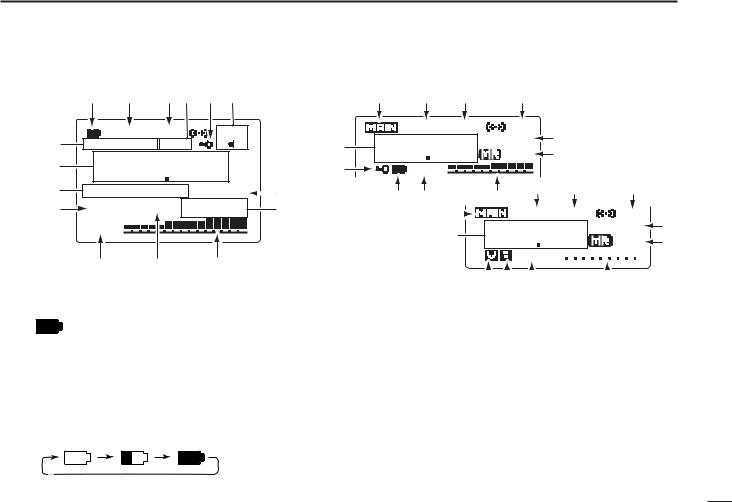
qBATTERY INDICATOR |
|
|
wDUPLEX INDICATORS (p. 20) |
|
|
|
|
|
|
|
|
|
|
|
|
|
|
|
|
|
|
|
|||||||||
“ |
” appears when the installed batteries have |
“+DUP” appears when plus semi-duplex, “–DUP” appears |
|||||||||||||||||||||||||||||
ample capacity. |
|
|
when minus semi-duplex (repeater) operation is selected. |
||||||||||||||||||||||||||||
•They do not appear when operating with an external power source.
“ ” appears when the batteries are nearing exhaustion.
•IC-R20 installed the BP-206 must be charged presently, but when it installed alkaline batteries can be operate for a while.
Scrolls while charging the installed BP-206. (p. 8)
Battery indicator blinks when completely charged.
eSIGNAL SQUELCH INDICATORS
“TSQL” appears while the tone squelch function is in use. (p. 45)
“DTCS” appears while the DTCS squelch function is in use. (p. 45)
“S” appears with the “TSQL” or “DTCS” indicator while the pocket beep function (with CTCSS or DTCS) is in use. (p. 45)
“VSC” appears while the VSC (Voice Squelch Control) function is in use. (p. 45)
6

1 PANEL DESCRIPTION
rANL/NB INDICATOR (pgs. 21, 52)
“ANL” appears when the ANL (Automatic Noise Limitter) function is in use. The ANL function is available only for AM mode.
“NB” appears when the noise blanker function is in use. The noise blanker function is available while in LSB/USB/CW modes.
tLOCK INDICATOR (p. 16)
Appears when the lock function is activated.
yAFC INDICATOR (p. 21)
Appears when the AFC function is activated.
• The AFC function is available for single band operation only.
uSKIP INDICATORS (p. 39)
“SKIP” appears when the selected memory channel is specified as a skip channel.
“PSKIP” appears when the displayed frequency is specified as a skip frequency.
iCHANNEL SELECTION INDICATOR (p. 11)
“µ ” and three digits channel number appear when memory channel is selected.
“å ” and three digits channel number appear when auto-memory write channel is selected.
“TV” appears when TV channel is selected.
(0–9) channel number appears when PreSet channel is selected.
“WX”* appears when weather channel is selected.
 *Available for the USA version only. “å ,” “0–9” and “TV”
  indications appear for single band operation only.
oSIGNAL STRENGTH INDICATOR
Shows the receiving signals relative to signal strength.
!0PRIORITY WATCH INDICATOR (p. 42) Appears when priority watch is in use.
!1ATTENUATOR INDICATOR (p. 19) Appears when the RF attenuator is in use.
!2VOLUME/DIAL EXCHANGE INDICATOR (p. 23)
“√ ” appears when the normal operation.
“∂ ” appears when the functions of the tuning control and volume control are traded.
!3MEMORY/BANK NAME INDICATOR
Shows the memory name or bank name.
•This indication is available when memory name or bank name is programmed.
!4FREQUENCY READOUT
Shows an operating frequency.
•The smaller readout appears at right when tuning step is selected 0.1 kHz or 0.01 kHz steps.
•The decimal point blinks during scan.
!5RECEIVE MODE INDICATOR (p. 16) Shows the selected receive mode.
• FM, WFM AM, LSB, USB and CW are available.
!6MAIN BAND INDICATOR (p. 24)
Shows the main band on upper display or lower display.
• This indication appears only when dualwatch operation.
7
BATTERY INSTALLATION/CHARGING 2 
■ Battery installation
Make sure receiver power is turned OFF before installing or replacing the batteries.
qRemove the battery cover from the receiver.
wFor alkaline battery use, attach the supplied battery spacer.
|
w |
q |
e |
|
eInstall 3 R6 (AA) size alkaline batteries.
• Be sure to observe the correct polarity.
|
1 |
|
|
D Battery pack installation |
2 |
|
q Remove the battery cover from the receiver.
wRemove the supplied battery spacer for R6 (AA) size battery use.
eInstall the Li-Ion battery pack (BP-206).
•Be sure to observe the correct direction.
•Charge the Li-Ion battery pack before use.
•Battery pack installation
•Battery pack removal
 Keep the battery contacts clean to avoid rust or poor contact.
  It’s a good idea to clean the battery terminals once a week.
8
2 BATTERY INSTALLATION/CHARGING
■ Caution
D Battery caution
CAUTION! NEVER short the battery terminals. Current will flow into metal objects, so be careful when placing battery pack in handbags, etc.
NEVER incinerate used battery packs or battery cells. Internal battery gas may cause explosion.
NEVER mix old and new batteries. Make sure all battery cells are the same brand, type and capacity.
Either of the above may cause a fire hazard or damage the receiver if ignored.
D Charging caution
Recommended temperature for charging: ±0˚C to +35˚C (; +32˚F to +95˚F)
Connect the supplied (or optional for some versions) AC adaptor or optional cigarette lighter cable only when charging the battery pack (BP-206). NEVER use other manufacture’s chargers.
AVOID leaving the battery pack in a fully charged, or completely discharged condition for long time. It causes shorter battery life. In case of leaving the battery pack unused for a long time, it must be kept safely after discharge, or use the battery for 2 or 3 hours, then remove it from the receiver.
If your battery pack seems to have no capacity even after being charged, fully charge the battery pack again. If the battery pack still does not retain a charge (or very little), a new battery pack must be purchased.
 CAUTION: BE SURE to disconnect the CP-18A/E from
the cigarette lighter socket when charging is finished, be-
 cause, a slight current still follows in the CP-18A/E and the
  vehicle’s battery will become exhausted.
■ Battery charging
D Regular charging
q Insert the battery pack (BP-206) into the receiver. (p. 8)
wPlug the AC adaptor (BC-149A/D*) into an AC outlet; or the optional CP-18A/E into a cigarette lighter socket.
*Not supplied with some versions.
eTurn OFF the receiver, then insert the adaptor plug into [DC] of the receiver.
 IC-R20
to [DC] jack
Turn power
 OFF.
OFF.
Optional CP-18A/E Cigarette lighter cable with DC-DC converter
to cigarette lighter socket
AC adaptor
BC-149A/D
to AC outlet
Charging periods: 8 hours (w/BP-206)
 RWARNING!: NEVER attempt to charge any other bat-
  teries. Because the IC-R20 can charge the BP-206 only.
9
D CP-18A/E fuse replacement
If the fuse blows or the receiver stops functioning while operating with the optional CP-18A/E, find the source of the problem if possible, and replace the damaged fuse with a new rated one (FGB 5 A) as shown below.
Fuse 5 A
Recommendation:
Charge the supplied battery pack for a maximum of 8 hours. Li-Ion batteries are different from Ni-Cd batteries in that it is not necessary to completely charge and discharge them to prolong the battery life. Therefore, charging the battery in intervals, and not for extended periods is recommended.
BATTERY INSTALLATION/CHARGING 2
D Rapid charging with the BC-156 |
|
|
The optional BC-156 provides rapid charging of battery pack |
|
|
2 |
||
(BP-206). |
||
|
||
• Charging periods: 2.5 hours (w/BP-206) |
|
Shorten or remove 
 the antenna.

 Turn power OFF.
AC adaptor |
Check the |
(supplied with BC-156) |
orientation. |
BC-156
 CAUTION: Shorten or remove the telescoping antenna be-
  fore charging to prevent the receiver from overturning.
 If the charge indicator flashes orange, there may be a
problem with the battery pack (or charger). Reinsert the  battery pack or contact your dealer.
10
 3 FREQUENCY AND CHANNEL SETTING
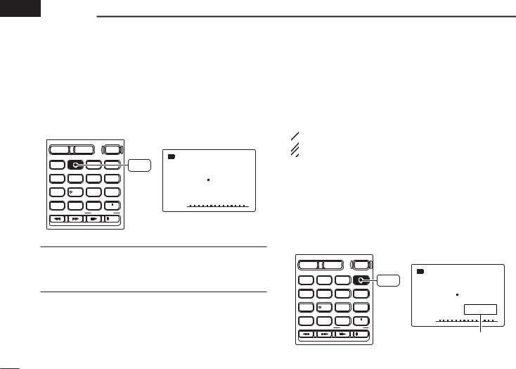
■ Mode selection
D VFO mode
VFO mode is used for the desired frequency setting within the frequency coverage.
Push [VFO MHz] to select VFO mode.
• VFO mode indication
DUALWATCH |
MAIN/SUB |
POWER |
|
|
|
|
|
-DUP TSQL |
AFC |
BAND |
|
MODE |
MR |
VFO |
MODE FM ANL |
|
|
|
SCAN |
S.MW |
MHz |
146 560 |
|
1 |
2 |
3 |
SCOPE |
|||
DIAL.SEL |
SWEEP |
CENTER |
|
|
|
|
T-SCAN |
SKIP |
M.N |
|
PSKIP |
|
|
|||
4 |
5 |
6 |
0AFC |
√ |
TONE |
SET |
TS |
|
|
7 |
8 |
9 |
LOCK |
|
ATT |
RF GAIN |
IC Recorder |
|
|
|
|
|
REC |
|
What is VFO?
VFO is an abbreviation of Variable Frequency Oscillator. Frequencies for receiving are generated and controlled by the VFO.
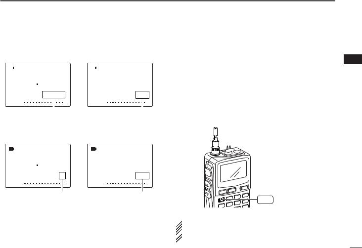
D Memory mode/PreSet*/TV*/Weather† channels
Memory mode is used for operation of memory channels which have programmed frequencies. PreSet channels are used for most-often used frequencies for quick recall.
 *Appears only when PreSet channels/TV channels are
  programmed via the optional CS-R20.
 †Available for the USA version only.
qPush [MR S.MW] several times to select the channel type.
•Memory/PreSet/TV /Weather channels can be selected in sequence
wRotate [R-DIAL] to select the desired channel.
•Only programmed memory channels can be selected.
•Entering keypad directly can be selected the desired memory channel.
•See p. 26 for memory programming details.
• Memory mode indication
DUALWATCH |
MAIN/SUB |
POWER |
|
|
|
|
|
|
|
|
|
-DUP TSQL |
AFC |
BAND |
VFO |
MODE |
MR |
MODE FM ANL |
|
|
|
MHz |
SCAN |
S.MW |
|
146 100 |
|
1 |
2 |
3 |
|
|||
SCOPE |
|
|||||
DIAL.SEL |
SWEEP |
CENTER |
|
|
|
|
T-SCAN |
SKIP |
M.N |
|
|
|
PSKIP |
4 |
5 |
6 |
0AFC |
√ |
µ |
001 |
TONE |
SET |
TS |
|
|
|
|
7 |
8 |
9 |
LOCK |
|
|
|
ATT |
RF GAIN |
IC Recorder |
|
|
|
|
|
|
|
REC |
“µ |
” and memory channel |
|
|
|
|
|
|||
number appear.
11
• Memory mode indication |
• TV channel indication |
||||||||||||
|
|
-DUP TSQL |
|
AFC |
|
|
-DUP TSQL |
AFC |
|||||
|
|
|
|
|
|||||||||
MODE FM ANL |
|
|
|
MODE WFMANL |
|
|
|
||||||
|
|
146 100 |
|
|
|
|
2 ch |
||||||
|
|
|
|
PSKIP |
|
|
|
|
PSKIP |
||||
|
√ |
µ |
001 |
|
|
√ |
TV |
||||||
|
|
|
|
|
|
|
|
|
|||||
|
|
|
|
|
|
|
|
|
|
|
|
|
|
|
|
|
|
|
|
||||||||
“µ |
” and memory channel |
|
“TV” indication appears. |
||||||||||
number appear. |
|
|
|
|
|
|
|
|
|
|
|||
• PreSet channel indication |
• Weather channel indication |
||||||||||||
|
|
|
|
|
|
|
(USA version only) |
||||||
-DUP TSQL |
AFC |
-DUP TSQL |
AFC |
MODE WFMANL |
|
MODE FM ANL |
|
76 000 |
1 |
|
|
|
PSKIP |
|
PSKIP |
√ |
0 |
√ |
WX |
PreSet channel number appears. |
“WX” indication appears. |
||
FREQUENCY AND CHANNEL SETTING 3
■ Operating band selection
The receiver can receive the AM broadcast, HF bands, 50 MHz, FM broadcast, VHF air, 144 MHz, 300 MHz, 400 MHz, 800 MHz,* 1200 MHz or 2400 MHz.
In VFO mode, push [BAND] several times to select the desired frequency band.
•If the other than VFO mode is selected, such as a memory/Pre-
Set/TV/Weather channel, push [VFO MHz] to select VFO mode first, then push [BAND] to select the desired band.
While pushing and holding [BAND], rotating [R-DIAL] also selects frequency band.


 [R-DIAL]
BAND
 Available frequency bands are different depending on ver-
sion. See the specification for details.
 *Some frequency ranges are prohibited for the USA ver-
  sion due to local regulation.
3
12
3 FREQUENCY AND CHANNEL SETTING
• Available frequency bands
MODE AM |
MODE AM |
MODE FM |
1620 |
5 000 |
51 000 |
AM broadcast band |
HF band |
50 MHz band |
|
: Push |
BAND |
|
|
|
|
|
||
MODE FM |
: Rotating while pushing |
BAND |
||
2425 000 |
||||
|
||||
|
|
|
||
2400 MHz band
Initial frequencies shown will differ according to version.
MODE WFM
76 000
FM broadcast band
MODE AM
118 000
VHF air band
MODE FM
146 010
144 MHz band
MODE FM |
MODE FM |
MODE FM |
MODE AM |
1295 000  800 000
  440 000
  370 000
1200 MHz band |
800 MHz band |
400 MHz band |
300 MHz band |
13
■ Setting a tuning step
The tuning step can be selected for each frequency band independently, however, the tuning steps, 8.33 kHz and 9 kHz, only appear when setting the tuning step for the VHF air band and AM broadcast band, respectively. The following tuning
steps are available for the IC-R20. |
|
|
||
• 0.01 kHz |
• 0.1 kHz |
• 1.0 kHz |
• 5.0 kHz |
• 6.25 kHz |
• 8.33 kHz* • 9.0 kHz* |
• 10.0 kHz |
• 12.5 kHz |
• 15.0 kHz |
|
• 20.0 kHz |
• 25.0 kHz |
• 30.0 kHz |
• 50.0 kHz |
• 100.0 kHz |
* Available for some frequency band only.
D Tuning step selection
qPush [VFO MHz] to select VFO mode, if necessary.
wPush [BAND] to select the desired frequency band.
•Or, while pushing and holding [BAND], rotate [R-DIAL] to select the desired frequency band.
e Push [9 TS] for 1 sec. to enter tuning step selecting condition. rRotate [R-DIAL] to select the desired tuning step.
tPush [9 TS] to return to VFO mode.
[R-DIAL] |
-DUP TSQL AFC |
|
|
MODE FM ANL |
|
|
146 010 |
|
BAND |
PSKIP |
|
√ |
||
|
||
VFO |
SET TS:5.0kHz |
|
|
||
MHz |
5 kHz tuning step |
|
TS |
9
FREQUENCY AND CHANNEL SETTING 3
■ Setting a frequency |
|
|
D Using the dial |
|
|
qPush [VFO MHz] to select VFO mode, if necessary. |
3 |
|
wSelect the desired frequency band with [BAND]. |
||
|
•Or, while pushing and holding [BAND], rotate [R-DIAL] to select the desired frequency band.
eRotate [R-DIAL] to select the desired frequency.
•The frequency changes according to the preset tuning steps. See the left section for setting the tuning step.
•Push [VFO MHz] for 1 sec. then rotate [R-DIAL] to change the frequency in 1 MHz steps, or push for 1 sec. again then rotate [R-DIAL] to change the frequency in 10 MHz steps. (Each push for 1 sec. toggles 1 MHz or 10 MHz tuning steps.)


 [R-DIAL]
BAND
VFO
MHz
MODE FM
146 010 00
[R-DIAL] changes the frequency according to the selected tuning step.
MODE FM
146 010 00
While pushing [VFO MHz], [R-DIAL] changes the frequency in 1 MHz steps (default).
14
3 FREQUENCY AND CHANNEL SETTING
D Using the keypad
The frequency can be directly set via numeral keys.
•When editing a frequency outside of the frequency range, the previously displayed frequency is automatically recalled after editing last digit.
qPush [VFO MHz] to select VFO mode, if necessary.
wEnter the desired frequency via the keypad.
•Direct input can be set until 1 kHz digit, rotate [R-DIAL] to set below 1 kHz frequency after set tuning steps, if necessary. (See the previous page for setting the tuning step.)
DUALWATCH
VFO
MHz
1 |
2 |
3 |
|
4 |
5 |
6 |
0AFC |
7 |
8 |
9 |
LOCK |
 Pushing [VFO MHz] omits the entry of 100 kHz and below, when you want to
  edit to these digits “0.” Push [DUALWATCH] to cancel the entry.
• Editting to 0.820 MHz • Editting to 1260 MHz • Changing 100 kHz and below.
|
MODE AM |
|
0AFC |
000 010 |
1 |
|
||
|
MODE AM |
|
LOCK |
000 010 |
2 |
|
||
|
MODE AM |
|
8 |
000 884 |
6 |
|
||
|
MODE AM |
|
2 |
000 824 |
0AFC |
|
MODE AM |
|
0 |
000 820 |
VFO |
|
MHz |
MODE FM
1 000
MODE FM
12 000 |
LOCK |
MODE FM
126 000 2
MODE FM
1260 000 4
MODE FM |
|
1260 000 |
0AFC |
|
Editting 1260.000 MHz to 1260.240 MHz
MODE FM
1260 240
MODE FM
1260 240
MODE FM
1260 240
MODE FM
1260 240
15
■ Receive mode selection
Receive modes are determined by the physical properties of the radio signals. The receiver has 6 receive modes: FM, WFM, AM, LSB, USB and CW modes. The mode selection is stored independently in each band and memory channels.
Typically, AM mode is used for the AM broadcast stations (0.495–1.620 MHz) and VHF air band (118–135.995 MHz), and WFM is used for FM broadcast stations (76–107.9 MHz).
Push [MODE SCAN] momentarily several times to select the desired receive mode.
|
MODE FM |
DUALWATCH MAIN/SUB POWER |
146 010 |
BAND |
VFO |
MODE |
MR |
MODE |
|
|
MHz |
SCAN |
S.MW |
SCAN |
PSKIP |
DIAL.SEL |
SWEEP |
CENTER |
|
||
|
|
FM mode |
|||
1 |
2 |
3 |
SCOPE |
|
T-SCAN SKIP M.N
4 |
5 |
6 |
0AFC |
MODE AM |
TONE |
SET |
TS |
|
|
|
118 000 |
|||
7 |
8 |
9 |
LOCK |
|
ATT |
RF GAIN |
IC Recorder |
||
REC |
PSKIP |
AM mode
MODE  WFM
WFM
76 000
PSKIP
WFM mode
FREQUENCY AND CHANNEL SETTING 3
■ Lock function
To prevent accidental frequency changes and unnecessary |
|
function access, use the lock function. |
3 |
|
Push [• LOCK] for 1 sec. to turn the lock function ON and OFF.
•“

 ” appears while the lock function is activated.
•The squelch control and volume control can be used while the lock function is in use with default setting. Either or both the squelch control and volume control can also be locked in set mode. (p. 49)
|
|
|
|
“ ” appears while the |
DUALWATCH |
MAIN/SUB |
POWER |
lock function is in use. |
|
BAND |
VFO |
MODE |
MR |
|
MHz |
SCAN |
S.MW |
-DUP TSQL AFC |
|
|
|
|||
DIAL.SEL |
SWEEP |
CENTER |
|
MODE FM ANL |
1 |
2 |
3 |
|
|
SCOPE |
146 010 |
|||
T-SCAN |
SKIP |
M.N |
|
|
4 |
5 |
6 |
0AFC |
|
TONE |
SET |
TS |
|
PSKIP |
7 |
8 |
9 |
LOCK |
√ |
ATT |
RF GAIN |
IC Recorder |
|
|
|
|
REC |
|
|
16
 4 BASIC OPERATION
■ Receiving
Make sure charged battery pack (BP-206) or brand new alkaline batteries are installed (p. 8).
qPush [POWER] for 1 sec. to turn power ON.
wRotate [L-DIAL] (or push [Y] or [Z]) to set the desired audio level.
•The frequency display shows the volume level while setting. See the section at right for details.
eSet the receiving frequency. (p. 14)
rSet the squelch level. (p. 18)
•While pushing [SQL], rotate [R-DIAL].
•The first click of [R-DIAL] indicates the current squelch level.
•“LEVEL 1” is loose squelch and “LEVEL 9” is tight squelch.
•“AUTO” indicates automatic level adjustment with a noise pulse count system.
•Push and hold [SQL] to open the squelch manually.
tWhen a signal is received:
•Squelch opens and audio is emitted.
•The S-meter shows the relative signal strength level.
r Push for setting the squelch (Push to monitor)
w Set audio level
 w Set audio level

 e Set frequency r Set squelch level
 q [POWER]
e Select band
■ Setting audio volume
The audio level can be adjusted through 39 levels.
Push and hold [SQL], rotate [L-DIAL] (or push [Y] or [Z]) to adjust the audio level.
•While using [Y]/[Z], pushing and holding either key change the audio level continuously.
•The display shows the volume level while setting.
|
-DUP TSQL AFC |
|
MODE FM ANL |
[L-DIAL] |
146 010 |
|
PSKIP |
SQL |
√ |
|
|
|
VOL |
|
Minimum setting |
|
(no audio) |
√
VOL
√
VOL
Maximum setting
17
 Loading...