


INSTRUCTION MANUAL
COMMUNICATIONS RECEIVER
iR5
This device complies with Part 15 of the FCC rules. Operation is subject to the following two conditions: (1) This device may not cause harmful interference, and (2) this device must accept any interference received, including interference that may cause undesired operation.
FOREWORD
Thank you for purchasing this Icom product. The IC-R5 COM- MUNICATIONS RECEIVER is designed and built with Icom’s superior technology and craftsmanship. With proper care, this product should provide you with years of trouble-free operation.
We want to take a couple of moments of your time to thank you for making your IC-R5 your radio of choice, and hope you agree with Icom’s philosophy of “technology first.” Many hours of research and development went into the design of your IC-R5.
DFEATURES
Covers 0.150–1309.995 MHz* wide
frequency range
*Some frequency bands are inhibited according to version
External power supply operation
1250 memory channels* with 18 banks
available
*200 auto write and 50 scan edge channels are included.
Built-in bar-antenna
New DMS (Dynamic Memory Scan) System
IMPORTANT
READ ALL INSTRUCTIONS carefully and completely before using the receiver.
SAVE THIS INSTRUCTION MANUAL— This instruction manual contains important operating instructions for the IC-R5.
EXPLICIT DEFINITIONS
WORD |
DEFINITION |
Personal injury, fire hazard or electric shock RWARNING! may occur.
CAUTION Equipment damage may occur.
NOTE
Recommended for optimum use. No risk of personal injury, fire or electric shock.
Icom, Icom Inc. and the 
 logo are registered trademarks of Icom Incorporated (Japan) in the United States, the United Kingdom, Germany, France, Spain, Russia and/or other countries.
i

PRECAUTION
RWARNING! NEVER operate the receiver with a earphone, headphones or other audio accessories at high volume levels. Hearing experts advise against continuous high volume operation. If you experience a ringing in your ears, reduce the volume level or discontinue use.
RWARNING! NEVER connect the receiver to an AC outlet. This may pose a fire hazard or result in an electric shock.
RWARNING! NEVER operate the receiver while driving a vehicle. Safe driving requires your full attention—any- thing less may result in an accident.
RWARNING! NEVER throw a battery cell into a fire since as internal battery gas can cause explosion.
RWARNING! NEVER disassemble the battery cell. If the battery cell’s internal material (electrolyte liquid) gets into your eyes, wash your eyes with water and obtain treatment from an eye doctor immediately.
NEVER connect the receiver to a power source of more than 6 V DC directly. This will damage the receiver.
NEVER connect the receiver to a power source using reverse polarity. This will damage the receiver.
NEVER expose the receiver to rain, snow or any liquids. The receiver may be damaged.
NEVER operate or touch the receiver with wet hands. This may result in an electric shock or damage the receiver.
NEVER solder the battery cell. This may damage the battery.
AVOID using or placing the receiver in direct sunlight or in areas with temperatures below –10°C (+14˚F) or above +60°C (+140˚F).
AVOID the use of chemical agents such as benzine or alcohol when cleaning, as they can damage the receiver’s surfaces.
Even when the receiver power is OFF, a slight current still flows in the circuits. Remove batteries from the receiver when not using it for a long time. Otherwise, the installed batteries will become exhausted, and will need to be recharged.
For U.S.A. only
CAUTION: Changes or modifications to this device, not expressly approved by Icom Inc., could void your authority to operate this device under FCC regulations.
ii

SUPPLIED ACCESSORIES
q |
w |
e |
r |
t
qAntenna ………………………………………………………1
wHand strap …………………………………………………1
eBelt clip ………………………………………………………1
rNi-Cd battery cells† …………………………………………2
tAC adapter* …………………………………………………1
*Not supplied with UK and Italy versions.
†Not supplied with Italy version.
OPERATING THEORY
Electromagnetic radiation which has frequencies of 20,000 Hz (20 kHz*) and above is called radio frequency (RF) energy because it is useful in radio transmissions. The IC-R5 receives RF energy from 0.150 MHz* to 1309.995 MHz and converts it into audio frequency (AF) energy which in turn actuates a loudspeaker to create sound waves. AF energy is in the range of 20 to 20,000 Hz.
*kHz is an abbreviation of kilohertz or 1000 hertz, MHz is abbreviation of megahertz or 1,000,000 hertz, where hertz is a unit of frequency.
OPERATING NOTES
The IC-R5 may receive its own oscillated frequency, resulting in no reception or only noise reception, on some frequencies.
The IC-R5 may receive interference from extremely strong signals on different frequencies or when using an external high-gain antenna.
iii

TABLE OF CONTENTS
FOREWORD .................................................. |
i |
|
IMPORTANT .................................................. |
i |
|
EXPLICIT DEFINITIONS ................................ |
i |
|
PRECAUTION ............................................... |
ii |
|
SUPPLIED ACCESSORIES ......................... |
iii |
|
OPERATING THEORY ................................. |
iii |
|
OPERATING NOTES ................................... |
iii |
|
TABLE OF CONTENTS ................................ |
iv |
|
QUICK REFERENCE GUIDE .................. |
I–VI |
|
|
■ Preparation ............................................. |
I |
|
■ Receiving a signal ................................ |
III |
|
■ Memory programming .......................... |
IV |
|
■ Programmed scan operation................. |
V |
1 |
PANEL DESCRIPTION ........................ |
1–4 |
|
■ Front, top and side panels .................... |
1 |
|
■ Function display .................................... |
3 |
2 |
BATTERY CHARGING ........................ |
5–6 |
|
■ Battery installation ................................. |
5 |
|
■ Caution .................................................. |
5 |
|
■ Battery charging .................................... |
6 |
3 FREQUENCY AND CHANNEL SETTING |
||
|
........................................................... |
7–10 |
|
■ VFO and memory channels................... |
7 |
|
■ Operating band selection....................... |
7 |
|
■ Setting a frequency................................ |
9 |
|
■ Setting a tuning step.............................. |
9 |
|
■ Selecting a memory channel ............... |
10 |
|
■ Lock function ....................................... |
10 |
4 |
BASIC OPERATION ........................ |
11–15 |
|
■ Receiving ............................................. |
11 |
|
■ Setting audio volume ........................... |
11 |
|
■ Squelch level setting............................ |
12 |
|
■ Receive mode selection ...................... |
12 |
|
■ Monitor function ................................... |
13 |
|
■ Attenuator function .............................. |
13 |
|
■ Duplex operation ................................. |
14 |
|
■ Dial select step .................................... |
15 |
5 |
MEMORY CHANNELS ..................... |
16–24 |
|
■ General description ............................. |
16 |
|
■ Memory channel programming............ |
16 |
|
■ Memory bank setting ........................... |
17 |
|
■ Memory bank selection........................ |
18 |
|
■ Programming memory/bank name ...... |
19 |
|
■ Selecting display type.......................... |
20 |
|
■ Copying memory contents................... |
21 |
|
■ Memory clearing .................................. |
22 |
|
■ Transferring memory contents............. |
23 |
|
■ Erasing/transferring bank contents...... |
24 |
6 |
SCAN OPERATION ......................... |
25–31 |
|
■ Scan types........................................... |
25 |
|
■ Full/band/programmed scan................ |
26 |
|
■ Scan edges programming ................... |
27 |
|
■ Memory/bank/all bank scan................. |
28 |
|
■ Auto memory write scan ...................... |
29 |
|
■ Skip channel/frequency setting............ |
30 |
|
■ Scan resume condition ........................ |
31 |
7 |
PRIORITY WATCH .......................... |
32–34 |
|
■ Priority watch types ............................. |
32 |
|
■ Priority watch operation ....................... |
33 |
8 TONE SQUELCH AND POCKET BEEP |
||
|
.......................................................... |
35–38 |
|
■ Tone/DTCS squelch operation............. |
35 |
|
■ Tone squelch frequency/DTCS code set- |
|
|
ting....................................................... |
36 |
■ DTCS polarity setting........................... |
37 |
■ Tone scan ............................................ |
38 |
9 SET MODE ...................................... |
39–47 |
■ General................................................ |
39 |
■ Set mode items.................................... |
40 |
10 OTHER FUNCTIONS ....................... |
48–53 |
■ Antenna selection ................................ |
48 |
■ [DIAL] function assignment.................. |
49 |
■ Weather channel operation ................. |
49 |
■ Data cloning ........................................ |
51 |
■ Auto power-off function........................ |
52 |
■ Partial reset ......................................... |
53 |
■ All reset ............................................... |
53 |
11 FREQUENCY TABLE ...................... |
54–61 |
■ TV channels......................................... |
54 |
■ VHF marine channels .......................... |
57 |
■ Weather channels................................ |
57 |
■ Other communications in the USA ...... |
58 |
■ Other communications— other countries |
|
............................................................. |
60 |
12 MAINTENANCE ............................... |
62–63 |
■ Troubleshooting ................................... |
62 |
■ CP-18A/E fuse replacement ................ |
63 |
13 SPECIFICATIONS ................................. |
64 |
14 OPTIONS ............................................... |
65 |
15 POCKET GUIDE .............................. |
66–67 |
16 CE .......................................................... |
68 |
1
2
3
4
5
6
7
8
9
10
11
12
13
14
15
16
iv
QUICK REFERENCE GUIDE
■ Preparation
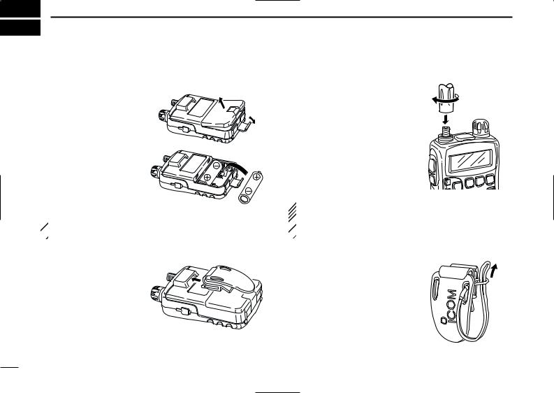
DBattery installation
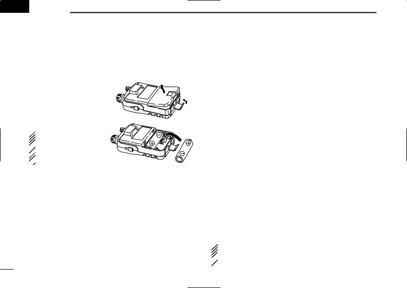
qRemove the battery cover from the receiver.
wInstall 2 R6(AA) size NiCd, Ni-MH or alkaline cell batteries.
• Be sure to observe the correct polarity.
• Charge Ni-Cd or Ni-MH batteries before use. (See the right page for charging instructions.)
 Keep battery the contacts clean. It’s a good idea to clean
  the battery terminals once a week.
DBelt clip
Conveniently attaches to your belt.
Slide the belt clip into the plastic loop on the back of the receiver.
I
DAntenna
Insert the supplied antenna into the antenna connector and screw down the antenna as shown at right.
NEVER hold the antenna when carrying the receiver.
Keep the jack cover attached when jack is not in use to protect the connectors from dust and moisture.
 For your information
Third-party antennas may increase receiver performance.  An optional AD-92SMA ANTENNA CONNECTOR ADAPTER is
  available to connect an antenna with a BNC connector.
DHandstrap
Slide the handstrap through the loop on the side of the belt clip as illustrated at right. Facilities carrying.
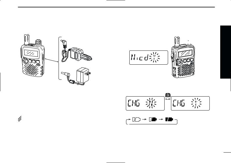
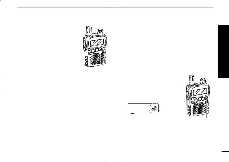
DCharging the battery
to [DC 6V] jack
IC-R5
Optional CP-18A/E Cigarette lighter cable with DC-DC converter
to cigarette lighter socket
AC adapter
to AC outlet
qInstall the Ni-Cd batteries.
•Ni-MH batteries can also be charged.
wPlug the AC adapter into an AC outlet.
eInsert the adapter plug into the [DC 6V] of the receiver. rThe battery confirmation is displayed as above right.
 RWARNING!:
 NEVER charge the alkaline batteries.
QUICK REFERENCE GUIDE
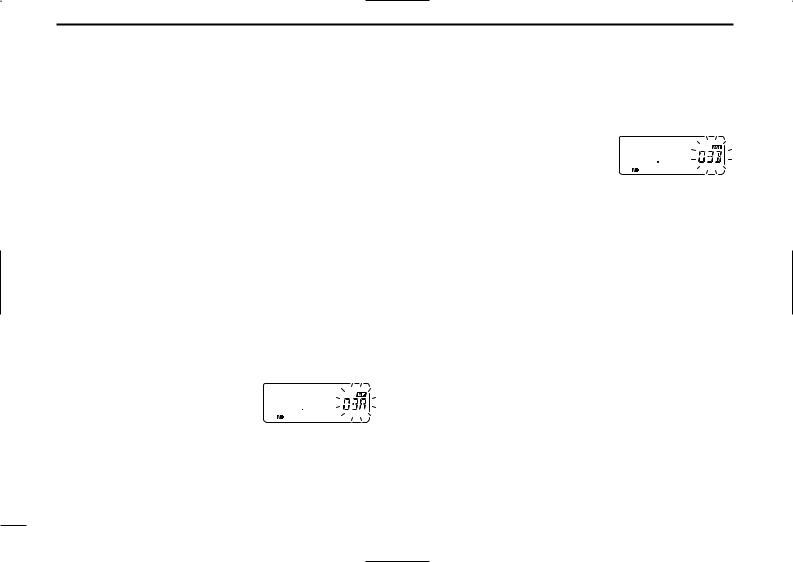
tRotate [DIAL] to select “Y” then push [BAND• ].
].
 [DIAL]
[BAND•  ]
] 
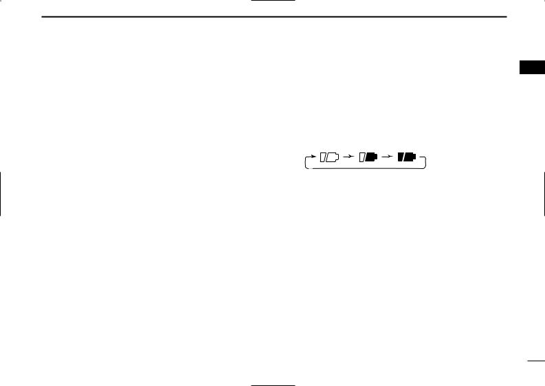
yThe charging confirmation is displayed as below.
uRotate [DIAL] to select “Y” then push [BAND• ] to start battery charging.
•The battery indicator scrolls during charge as below.
•Both segments blink when completely charged.
Quick reference guide
II
QUICK REFERENCE GUIDE
■ Your first scanning experience
Now that you have your IC-R5 ready, you are probably excited to start listening. We would like to take you through a few basic operation steps to make your first “Scanning Experience” enjoyable.
DAbout default setting
The [DIAL] control function can be traded with [Y]/[Z] keys function in set mode. However, in this QUICK REFERENCE GUIDE, the factory default setting ([DIAL] sets operating frequency) is used for simple instruction.
DBasic operation
1. Turning ON the receiver
Push [PWR] for 1 sec. to turn the power ON.
[PWR] 

2. Adjusting audio level
Push [Y]/[Z] to set the desired audio level.
3. Adjusting squelch level
While pushing [SQL], rotate [DIAL] to set the squelch level.
4.Tune the desired frequency
The tuning dial will allow you to dial in the frequency you want to operate. Pages 9 and 15 will instruct you on how to set the tuning speed.
qPush [BAND• ] several times to select the desired frequency band.
•While pushing [BAND• ], rotate [DIAL] also select frequency band.
[DIAL]
[SQL]  [Y]/[Z]
[DIAL]
[BAND•  ]
]
wRotate [DIAL] to set the desired receive frequency.
•While pushing [FUNC], rotate [DIAL] to select frequency in 1 MHz step.
III
5. Receive mode selection
Push [MODE•SCAN] several times to select the desired receive mode.
•FM, WFM and AM are available.
[MODE•SCAN]
QUICK REFERENCE GUIDE
■ Memory programming
The IC-R5 has a total of 1250 memory channels (including 200 auto write channels and 50 scan edges) for storing often used receive frequency, mode, etc.
1. Setting frequency
In VFO mode, set the desired receive frequency mode.
•When “ ” indicator is displayed, push [V/M•S.MW•~] to select the VFO mode.
2. Selecting a memory channel
Push [V/M•S.MW•~] for 1 sec., |
[DIAL] |
|
then rotate [DIAL] to select the desired memory channel.
• “ ” indicator and memory channel number blink.
[V/M•S.MW•~]
3. Writing a memory channel
Push [V/M•S.MW•~] for 1 sec. until 3 beeps sound.
•Memory channel number automatically increases when continuing to push [V/M•S.MW•~] after programming.
Quick reference guide
IV
QUICK REFERENCE GUIDE
■ Programmed scan operation
25 pairs, 50 channels of memories are used for programmed scan operation, that specifying a scanning ranges. The programmed scan scans between “xxA” and “xxB” (xx=00 to 24) frequencies. Therefore, before operating the programmed scan, different frequencies must be programmed into “A” and “B” channels.
DProgramming scan edges
A start frequency must be programmed into a “xxA,” and end frequency must be programmed into a “xxB” memory channel.
1. Setting frequency
In VFO mode, set the desired receive frequency mode.
•When “ ” indicator is displayed, push [V/M•S.MW•~] to select the VFO mode.
2. Selecting a scan edge channel “A”
Push [V/M•S.MW•~] for 1 sec., then rotate [DIAL] to select one of the de-
sired scan edge channel “A.”
• “ ” indicator and scan edge channel number blink.
3. Writing a memory channel
Push [V/M•S.MW•~] for 1 sec. until 3 beeps sound.
•Scan edge channel “B” is automatically selected when continuing to push [V/M•S.MW•~] after programming.
•After programming is completed, return to VFO indication.
4. Selecting a scan edge channel “B”
Push [V/M•S.MW•~] for 1 sec., then rotate [DIAL] to select one of the desired scan edge channel “B.”
•“ ” indicator and scan edge channel number blink.
•When the scan edge channel “B” is already selected at step 3. (continuing to push [V/M•S.MW•~] after programming), skip this step.
5. Writing a memory channel
Push [V/M•S.MW•~] for 1 sec. until 3 beeps sound.
•The next scan edge channel “A” is automatically selected when continuing to push [V/M•S.MW•~] after programming.
•After programming is completed, return to VFO indication.
V
DStarting scan
1. Select VFO mode.
Push [V/M•S.MW•~] to select the VFO mode for full, band and programmed scan operation.
•Select memory mode by pushing [V/M•S.MW•~] again for memory or bank scan.
2. Selecting a scanning type
Push [MODE•SCAN] for 1 sec., then rotate [DIAL] to select one of the desired scanning type.
•Available scan types when VFO mode is selected; “ALL” for full scan; “BAND” for the selected band; one of “PROGxx” (xx=0 to 24) for programmed scan.
•Available scan types when memory bank is selected; “ALL” for all bank scan; “BANK” for the selected bank scan.
•Scan type indication examples
•Full scan
 [DIAL]
• Program scan


 [MODE•SCAN]
• Bank scan
QUICK REFERENCE GUIDE
3. Starting scan
Push [MODE•SCAN] to start scan.
• Rotate [DIAL] to change the scanning direction.
• Full/Band scan |
|
• Programmed scan |
|
WFM AM |
P SKIP |
WFM AM |
P SKIP |
• Memory/All bank scan |
• Bank scan |
|
|
WFM AM DUP T SQL |
DTCS |
WFM AM DUP T SQL |
DTCS |
4. Cancelling scan
Push [MODE•SCAN] again to stop scan.
For your information
The memory channel number you program the scan edges into correlate “PROGxx” as follows:
00A/00B: Scans between frequencies programmed in 00A and 00B channels, and select “PROG 00”
01A/01B: Scans between frequencies programmed in 01A and 01B channels, and select “PROG 01”
•
•
•
•
23A/23B: Scans between frequencies programmed in 23A and 23B channels, and select “PROG 23”
24A/24B: Scans between frequencies programmed in 24A and 24B channels, and select “PROG 24”
Quick reference guide
VI
 1 PANEL DESCRIPTION
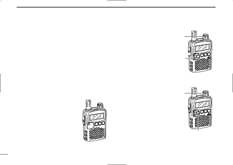
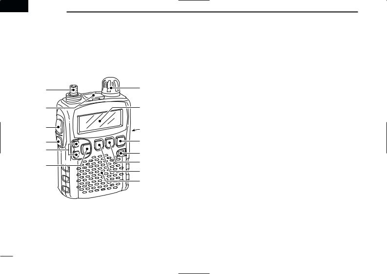
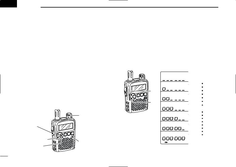
■ Front, top and side panels
q |
w |
u
Function display (pgs 3, 4)
e |
i |
|
|
r |
o |
t |
!0 |
|
|
y |
!1 |
|
|
|
!2 |
Speaker
qANTENNA CONNECTOR (p. I)
Connects the supplied antenna.
•An optional AD-92SMA is available for connecting an antenna with a BNC connector.
wEXTERNAL SPEAKER CONNECTOR [SP]
Connect an optional earphone or headphone.
The internal speaker will not function when any external equipment is connected. (See p. 65 for a list of available options.)
eFUNCTION SWITCH [FUNC]
While pushing this switch, access to secondary function.
rSQUELCH SWITCH [SQL]
Push and hold to temporarily open the squelch and monitor the operating frequency. (p. 13)
While pushing this switch, rotate [DIAL]* to adjust the squelch level. (p. 12)
tUP/DOWN SWITCHES [Y]/[Z]
Adjusts audio volume level.* (p. 11)
yBAND•LOCK SWITCH [BAND• ]
]
Push to select the operating frequency band. (p. 7)
After pushing [FUNC], push for 1 sec. to toggle the lock function ON and OFF. (p. 10)
1

uCONTROL DIAL [DIAL]
Rotate to select the operating frequency.* (p. 9)
While scanning, changes the scanning direction.* (p. 26)
While pushing [SQL], sets the squelch level.* (p. 12)
While pushing [FUNC], sets the operating frequency in 100 kHz, 1 MHz or 10 MHz in VFO mode.* (p. 9)
While pushing [FUNC], selects the memory channel in 10 channels steps in memory mode.* (p. 10)
While pushing [BAND• ], selects the operating band in VFO mode.* (p. 7)
iEXTERNAL DC-IN CONNECTOR [DC 6V] (p. 6) Connects an AC adapter or an optional cigarette lighter cable for both charging the installed re-chargeable battery and operating.
oVFO/MEMORY•MEMORY WRITE SWITCH [V/M•S.MW•~]
Toggles between VFO and memory mode. (p. 7)
Push for 1 sec. to enter memory edit condition. (p. 16)
After pushing [FUNC], select scan skip condition. (p. 30)
!0POWER SWITCH [PWR]
Push for 1 sec. to turn the receiver power ON and OFF.
!1MODE•SCAN SWITCH [MODE•SCAN]
Push to select the receive mode. (p. 12)
Push for 1 sec. to start a scan. (p. 26)
While pushing [FUNC], start a tone scan. (p. 38)
PANEL DESCRIPTION |
1 |
|
!2TUNING STEP•SET SWITCH [TS•SET] |
|
|
1 |
||
Push to enter tuning step selecting mode. (p. 9) |
|
|
Push for 1 sec. to enter set mode. (p. 39)
While pushing [FUNC], trade [DIAL] and [Y]/[Z] function. (p. 49)
*The function of [DIAL] and [Y]/[Z] can be traded. See page 49 for details.
2
1 PANEL DESCRIPTION
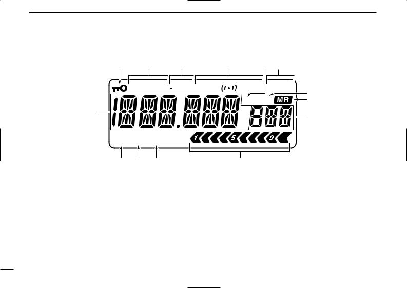
■ Function display
w e r t y u
WFM AM DUP T SQL |
DTCS P SKIP |
i |
|
R PRIO |
|
|
o |
|
q |
75 |
|
|
50 |
!0 |
|
25 |
|
ATT  VOL
VOL
!4 !3 !2
qFREQUENCY READOUT
Shows variety of information, such as an operating frequency, set mode contents, memory names.
•The smaller “75,” “50” and “25” to the right of the readout indicate 0.75, 0.5 and 0.25 kHz, respectively.
•The decimal point blinks during scan.
wLOCK INDICATOR (p. 10)
Appears when the lock function is activated.
eRECEIVE MODE INDICATOR (p. 12) Shows the selected receive mode.
• FM, WFM and AM are available.
!1
rDUPLEX INDICATORS (p. 14)
“DUP” appears when plus duplex, “–DUP” appears when minus semi-duplex (repeater) operation is selected.
tTONE INDICATORS
“T SQL” appears while the tone squelch function is in use. (p. 35)
“DTCS” appears while the DTCS squelch function is in use. (p. 35)
“S” appears with the “T SQL” or “DTCS” indicator while the pocket beep function (with CTCSS or DTCS) is in use. (p. 35)
3
yAUTO WRITE CHANNEL INDICATOR (p. 29) Appears when auto write channel is selected.
uSKIP INDICATORS (p. 30)
“SKIP” appears when the selected memory channel is specified as a skip channel.
“P SKIP” appears when the displayed frequency is specified as a skip frequency.
iPRIORITY WATCH INDICATOR (p. 33)
Appears when priority watch is in use.
oMEMORY INDICATOR (pgs. 7, 10) Appears when memory mode is selected.
!0MEMORY CHANNEL NUMBER INDICATORS
Shows the selected memory channel number. (pgs. 7, 10)
!1SIGNAL STRENGTH INDICATOR (p. 11)
Shows the relative signal strength while receiving signals.
!2VOLUME EXCHANGE INDICATOR (p. 49)
Appears when the function of [DIAL] and [Y]/[Z] are traded.
PANEL DESCRIPTION |
1 |
!3BATTERY INDICATOR |
1 |
Both segments appear when the installed batteries have ample capacity.
• They do not appear when operating with an external power source.
Only the right segment “ ” appears when the batteries are nearing exhaustion.
Scrolls while charging the installed rechargeable batteries. (p. 6)
Both segments blink when completely charged.
!4ATTENUATOR INDICATOR (p. 13) Appears when the RF attenuator is in use.
4
 2 BATTERY CHARGING
■ Battery installation
Before installing, or replacing the batteries, push [PWR] for 1 sec. to turn the power OFF.
qRemove the battery cover from the receiver.
wInstall 2 R6 (AA) size NiCd or Ni-MH batteries.
• Be sure to observe the correct polarity.
 Keep the battery contacts
clean to avoid rust or
 poor contact. It’s a good
  idea to clean the battery
  terminals once a week.
■ Caution
DBattery caution
•CAUTION! NEVER short the battery terminals. Also, current may flow into nearby metal objects such as a necklace, so be careful when placing battery cells in handbags, etc.
•NEVER mix old and new batteries.
•Make sure all battery cells are the same brand, type and capacity.
Either of the above may cause a fire hazard or damage the receiver if ignored.
•NEVER incinerate used battery cells. Internal battery gas may cause explosion.
If your re-chargeable batteries seem to have no capacity even after being charged, completely discharge them by leaving the power ON overnight. Then fully charge the batteries again. If the batteries still does not retain a charge (or very little charge), a new battery cells must be purchased.
DCharging caution
RWARNING! NEVER charge dry or alkaline batteries.
AVOID over charging— The installed re-chargeable batteries can be charged during operation when the AC adapter or the optional cigarette lighter cable is connected. To prevent over charging, the IC-R5 has charging timer that automatically disconnecting the charging line electronically after 15 hours from charging. However, the charging timer will reset and start charging again when disconnect then re-connecting the AC adapter or CP-18A/E more than 1 min. interval.
•Recommended temperature for charging: ±0˚C to +40˚C (; +32˚F to +140˚F)
•Connect the supplied (or optional for UK and Italy versions) AC adapter or optional cigarette lighter cable only when charging the installed Ni-Cd or Ni-MH batteries. NEVER use other manufactures’ chargers.
 CAUTION: BE SURE to disconnect the CP-18A/E from
the cigarette lighter socket when charging is finished, be-
 cause, a slight current still follows in the CP-18A/E and the
  vehicle’s battery will become exhausted.
5

■ Battery charging
DCharging connections
|
Optional CP-18A/E |
|
Cigarette lighter cable |
|
with DC-DC converter |
|
to cigarette |
|
lighter socket |
to [DC 6V] |
AC adapter |
jack |
|
IC-R5 |
to AC outlet |
|
• Charging periods: Approx. 10 hours
DCharging description
qInstall the Ni-Cd batteries. (See left page)
• Ni-MH batteries can also be charged.
wPlug the AC adapter into an AC outlet; or the optional CP18A/E into a cigarette lighter socket.
eInsert the adapter plug into [DC 6V] of the receiver.
•Once the batteries are removed for more then 2 sec., the following operations are necessary.
rThe battery type confirmation is displayed as above right.
•When no confirmation display is indicated, insert the adapter plug while pushing [FUNC].
BATTERY CHARGING 2
tRotate [DIAL] to select “Y” then push [BAND• |
]. |
2 |
 [DIAL]
[BAND•  ]
] 
yThe charging confirmation is displayed.
uRotate [DIAL] to select “Y” then push [BAND• ] to start battery charging.
•The battery indicator scrolls during charge as below.
•When the batteries are charged completely, the battery indicator (both segments) blinks.
•Takes approximately 10 hours for fully charge with the supplied Ni-Cd cells.
6

 3 FREQUENCY AND CHANNEL SETTING
■ VFO and memory channels
The IC-R5 has 2 normal operating modes: VFO mode and memory mode.
VFO mode is used for the desired frequency setting within the frequency coverage.
Push [V/M•S.MW•~] to select VFO mode.
Memory mode is used for the desired frequency setting within the frequency coverage.
Push [V/M•S.MW•~] to select memory mode.
•See p. 16 for memory programming details.
• VFO mode indication
[DIAL] |
FM |
P SKIP |
|
|
• Memory mode indication


 [V/M•S.MW•~] FM
“ ” and memory channel number appear.
What is VFO?
VFO is an abbreviation of Variable Frequency Oscillator. Frequencies for receiving are generated and controlled by the VFO.
■ Operating band selection
The receiver can receive the AM broadcast, HF band, 50 MHz, FM broadcast, VHF air, 144 MHz, 300 MHz, 400 MHz, 800 MHz,* 1200 MHz, television channels or Weather channels†.
Push [BAND• ] several times to select the desired frequency band.
•When a memory mode is selected, push [V/M•S.MW•~] to se-
lect VFO mode first, then push [BAND• ] to select the desired band.
While pushing and holding [BAND• ], rotating [DIAL] also selects frequency band.
 [DIAL]


 [BAND•
 ]
]
 Available frequency bands are differ depending on version.
See the specification for details.
 *Some frequency ranges are inhibited for the USA version
  due to local regulation.
 †Available for the USA version only.
7

FREQUENCY AND CHANNEL SETTING 3
• Available frequency bands
AM
AM broadcast band
FM
Weather channels*
WFM
TV channels†
AM FM
HF band 50 MHz band
 : Push
 Rotating
  while pushing
Showing initial frequencies are differ according to version. *Available for the USA version only
†Appears only when TV channels are programmed via the optional CS-R5.
WFM
3
FM broadcast band
AM
VHF air band
FM
144 MHz band
FM FM FM AM
1200 MHz band 800 MHz band 400 MHz band 300 MHz band
8
3 FREQUENCY AND CHANNEL SETTING
■ Setting a frequency
qPush [V/M•S.MW•~] to select VFO mode, if necessary.
wSelect the desired frequency band with [BAND• ].
].
•Or, while pushing and holding [BAND• ], rotate the [DIAL] to select the desired frequency band.
eRotate [DIAL] to select the desired frequency band.
•The frequency changes according to the preset tuning steps. See the right section for setting the tuning step.
•While pushing and holding [FUNC], rotate [DIAL] to change the frequency in 1 MHz steps (default).
|
FM |
[DIAL] |
75 |
25 |
|
|
50 |
[DIAL] changes the frequency [FUNC] according to the selected tuning
step.
|
|
FM |
[BAND• |
] |
75 |
|
|
50 |
|
|
25 |
While pushing [FUNC], [DIAL] changes the frequency in 1 MHz steps (default).
 The 1 MHz tuning step (dial select step) can be set to
  100 kHz, 1 MHz or 10 MHz tuning steps in set mode. See
  p. 15 for details.
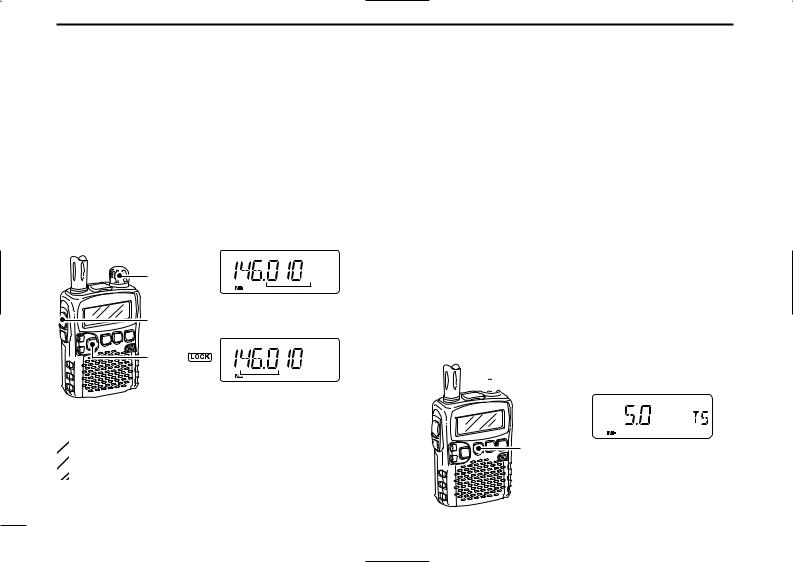
■ Setting a tuning step
The tuning step can be selected for each frequency band, however, the tuning steps, 8.33 kHz and 9 kHz, are appeared when setting the tuning step for the VHF air band and AM broadcast band, respectively. The following tuning steps are
available for the IC-R5. |
|
|
|
• 5.0 kHz |
• 6.25 kHz |
• 8.33 kHz |
• 9.0 kHz |
• 10.0 kHz |
• 12.5 kHz |
• 15.0 kHz |
• 20.0 kHz |
• 25.0 kHz |
• 30.0 kHz |
• 50.0 kHz |
• 100.0 kHz |
DTuning step selection
qPush [V/M•S.MW•~] to select VFO mode, if necessary.
wPush [BAND• ] to select the desired frequency band.
•Or, while pushing and holding [BAND• ], rotate the [DIAL] to select the desired frequency band.
ePush [TS•SET] to enter tuning step selecting condition. rRotate [DIAL] to select the desired tuning step.
tPush [TS•SET] to return to VFO mode.
 [DIAL]
[TS•SET] |
5 kHz tuning step |
9
■ Selecting a memory channel
qPush [V/M•S.MW•~] to select the memory mode.
• “ ” appears when a memory channel is selected.
wRotate [DIAL] to select the desired memory channel.
•Only programmed memory channels can be selected.
•While pushing and holding [FUNC], rotate [DIAL] to select a memory channel in 10 channels steps.
 [DIAL]
FM
[FUNC]


 [V/M•S.MW•~]
[DIAL] changes the memory channel.
FREQUENCY AND CHANNEL SETTING 3
■ Lock function
To prevent accidental frequency changes and unnecessary |
|
function access, use the lock function. |
3 |
|
While pushing [FUNC], push [BAND• ] for 1 sec. to turn the lock function ON and OFF.
•“ ” appears while the lock function is activated.
•[SQL] and [Y]/[Z] can be used while the lock function is in use with default setting. Either or both [SQL] and [Y]/[Z] keys are also be locked in set mode. (p. 43)
|
|
FM |
P SKIP |
[FUNC] |
|
VOL |
|
|
|
||
[BAND• |
] |
” |
appears while the |
|
“ |
||
lock function is in use.
10
 4 BASIC OPERATION
■ Receiving
Make sure charged Ni-Cd or brand new alkaline batteries are installed (p. 5).
qPush [PWR] for 1 sec. to turn power ON.
wPush [Y] or [Z] to set the desired audio level.
•The frequency display shows the volume level while setting. See the section at right for details.
eSet the receiving frequency. (p. 9)
rSet the squelch level. (p. 12)
•While pushing [SQL], rotate [DIAL].
•The first click of [DIAL] indicates the current squelch level.
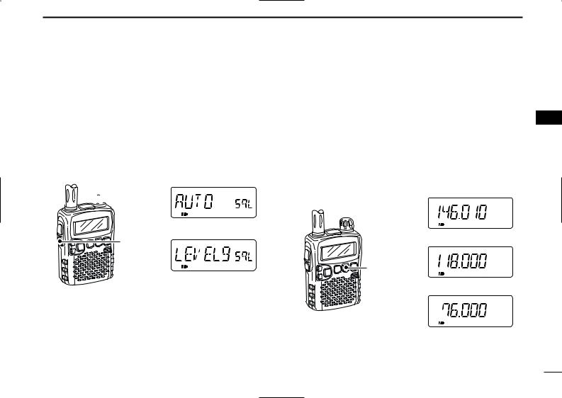
•“LEVEL 1” is loose squelch and “LEVEL 9” is tight squelch.
•“AUTO” indicates automatic level adjustment with a noise pulse count system.
•Push and hold [SQL] to open the squelch manually.
tWhen a signal is received:
•Squelch opens and audio is emitted.
•The S-meter shows the relative signal strength level.
r Push for setting |
e Set frequency |
|
r Set squelch level |
||
the squelch |
||
|
||
(Push to monitor) |
|
w Set audio level |
q [PWR] |
|
e Select band
■ Setting audio volume
The audio level can be adjusted through 32 levels.
Push [Y] or [Z] to adjust the audio level.
•Beep tone sounds while setting. The tone sound let you know the approximate sound level.
•Pushing and holding either key change the audio level continuously.
•The display shows the volume level while setting.
INDICATION |
AUDIO LEVEL |
Minimum setting (no audio)
[Y]
[Z] |
Initial setting
Muximum setting
11
■ Squelch level setting
The squelch circuit mutes the received audio signal depending on the signal strength. The receiver has 9 squelch levels, a continuously open setting and an automatic squelch setting.
While pushing and holding [SQL], rotate [DIAL] to select the squelch level.
•“LEVEL 1” is loose squelch and “LEVEL 9” is tight squelch.
•“AUTO” indicates automatic level adjustment with a noise pulse count system.
•“OPEN” indicates continuously open setting.
 [DIAL]
Automatic squelch
[SQL]
Maximum level
BASIC OPERATION 4
■ Receive mode selection
Receive modes are determined by the physical properties of |
|
the radio signals. The receiver has 3 receive modes: FM, AM |
|
and WFM modes. The mode selection is stored indepen- |
4 |
dently in each band and memory channels. |
Typically, AM mode is used for the AM broadcast stations (0.495–1.620 MHz) and air band (118–135.995 MHz), and WFM is used for FM broadcast stations (76–107.9 MHz).
Push [MODE•SCAN] several times to select the desired receive mode.
FM P SKIP
|
FM mode |
AM |
P SKIP |
[MODE•SCAN] |
|
|
AM mode |
WFM |
P SKIP |
WFM mode
12

4 BASIC OPERATION
■ Monitor function
This function is used to listen to weak signals without disturbing the squelch setting or to open the squelch manually even when mute functions such as the tone squelch are in use.
Push and hold [SQL] to monitor the operating frequency.
•The 1st segment of the S-meter blinks.
FM |
P SKIP |
[SQL]
The 1st segment blinks
 The [SQL] switch can be set to ‘sticky’ operation in ex-
  panded set mode. See page 43 for details.
■ Attenuator function
The attenuator prevents a desired signal from distorting when very strong signals are near the desired frequency or when very strong electric fields, such as from a broadcasting station, are near your location.
While pushing [FUNC], push [SQL] to toggle the attenuator function ON and OFF.
• “ATT” appears when the attenuator functions is in use.
FM |
P SKIP |
[FUNC]
ATT
[SQL]
“ATT” appears while the attenuator functions is in use.
13
 Loading...