


 Loading...
INSTRUCTION MANUAL
VHF MARINE TRANSCEIVERS
iM506
iM506GE

PREFACE
Thank you for choosing this Icom product.
This product is designed and built with Icom’s state of the art technology and craftsmanship. With proper care, this product should provide you with years of trouble-free operation.
We appreciate you making the IC-M506/IC-M506GE your transceiver of choice, and hope you agree with Icom’s philosophy of “technology first.” Many hours of research and development went into the design of your IC-M506/IC-M506GE.
DDFEATURES
Integrated AIS Receiver * NMEA 2000™ Connectivity *
2 minutes Last Call Voice Recording Superb Active Noise Cancelling
*Depends on transceiver version.
CLEAN THE TRANSCEIVER AND MICROPHONE THOROUGHLY WITH FRESH WATER after exposure to water including salt, otherwise, the keys and switch may become inoperable due to salt crystallization.
IMPORTANT
READ ALL INSTRUCTIONS carefully and completely before using the transceiver.
SAVE THIS INSTRUCTION MANUAL — This instruction manual contains important operating instructions for the IC-M506/IC-M506GE.
EXPLICIT DEFINITIONS
WORD |
DEFINITION |
|
RWARNING! |
Personal injury, fire hazard or electric |
|
shock may occur. |
||
|
||
CAUTION |
Equipment damage may occur. |
|
NOTE |
If disregarded, inconvenience only. No risk |
|
of personal injury, fire or electric shock. |
||
|
||
|
|
Icom is not responsible for the destruction or damage to the Icom transceiver, if the malfunction is because of:
•Force majeure, including, but not limited to, fires, earthquakes, storms, floods, lightning, other natural disasters, disturbances, riots, war, or radioactive contamination.
•The use of Icom transceivers with any equipment that is not manufactured or approved by Icom.
i

IN CASE OF EMERGENCY
If your vessel requires assistance, contact other vessels and the Coast Guard by sending a Distress call on Channel 16.
USING CHANNEL 16
DISTRESS CALL PROCEDURE
1.“MAYDAY MAYDAY MAYDAY.”
2.“THIS IS ...............” (name of vessel).
3.Say your call sign or other description of the vessel (AND 9 digit DSC ID if you have one).
4.“LOCATED AT ...............” (your position).
5.State the nature of the distress and assistance required.
6.Give any other information which might facilitate the rescue.
Or, transmit your Distress call using digital selective calling on Channel 70.
USING DIGITAL SELECTIVE CALLING (Ch 70)
DISTRESS CALL PROCEDURE
1.While lifting up the key cover, hold down [DISTRESS] for 3 seconds until you hear 3 short beeps and then one long beep.
2.Wait for an acknowledgment on Channel 70 from a coast station.
• After the acknowledgement is received, Channel 16 is automatically selected.
3.Hold down [PTT], then transmit the appropriate information as listed to the left.
INSTALLATION NOTE
Installation:
The installation of this equipment should be made in such a manner as to respect the EC recommended electromagnetic field exposure limits. (1999/519/EC)
The maximum RF power available from this device is 25 watts. The antenna should be installed as high as possible for maximum efficiency and the installation height should be at least 1.4 meters above any accessible position. In the case where an antenna cannot be installed at a reasonable height, then the transmitter should neither be continuously operated for long periods if any person is within a distance of 1.4 meters of the antenna, nor operated at all if any person is touching the antenna.
It is recommended that antenna of a maximum gain of 3 dB are used. If higher gain antenna are required then please contact your Icom distributor for revised installation recommendations.
Operation:
The exposure to RF electromagnetic field is only applicable when this device is transmitting. This exposure is naturally reduced due to the nature of alternating periods of receiving and transmitting. Keep your transmissions to the minimum necessary.
ii

PRECAUTIONS
RWARNING! NEVER connect the transceiver to an AC outlet. This could cause a fire, electric shock and damage the transceiver.
RWARNING! NEVER connect the transceiver to a power source of more than 16 V DC, such as a 24 V battery. This could cause a fire and damage the transceiver.
RWARNING! NEVER reverse the DC power cable polarity when connecting to a power source. This could cause a fire, electric shock and damage the transceiver.
RWARNING! NEVER remove the fuse holders on the DC cable. This could cause a fire, electric shock and damage the transceiver.
RWARNING! NEVER operate the transceiver during a lightning storm. It may result in an electric shock, cause a fire or damage the transceiver. Always disconnect the power source and antenna before a storm.
CAUTION: NEVER place the transceiver where normal operation of the vessel may be hindered or where it could cause bodily injury.
KEEP the transceiver and microphone at least 1 m away from the vessel’s magnetic navigation compass.
DO NOT place or leave the transceiver in areas with temperatures below –20°C or above +60°C or, in areas subject to intense sunlight, such as the dashboard.
DO NOT use harsh solvents such as benzine or alcohol to clean the transceiver, as they will damage the transceiver’s surfaces. If the transceiver becomes dusty or dirty, wipe it clean with a soft, dry cloth.
DO NOT disassemble or modify the transceiver for any reason.
BE CAREFUL! The transceiver rear panel will become hot when operating continuously for long periods of time.
Place the transceiver in a secure place to avoid inadvertent use by children.
BE CAREFUL! The transceiver meet IPX8 requirements and the optional HM-195 commandmicIV™ meet IPX7 requirements for waterproof protection. However, once the transceiver has been dropped, waterproof protection cannot be guaranteed because of possible damage to the transceiver’s case or the waterproof seal.
*Except for the DC power connector, NMEA In/Out leads and AF Out leads.
Icom, Icom Inc. and Icom logo are registered trademarks of Icom Incorporated (Japan) in Japan, the United States, the United Kingdom, Germany, France, Spain, Russia, Australia, New Zealand, and/or other countries.
COMMANDMIC is a registered trademark of Icom Incorporated (Japan) in Japan and the United States.
iii
ABOUT CE AND DOC
Hereby, Icom Inc. declares that the versions of IC-M506GE which have the “CE” symbol on the product, comply with the essential requirements of the Radio Equipment Directive,
2014/53/EU, and the restriction of the use of certain hazardous substances in electrical and electronic equipment Directive, 2011/65/EU. The full text of the EU declaration of conformity is available at the following internet address:
http://www.icom.co.jp/world/support/
DISPOSAL
The crossed-out wheeled-bin symbol on your
product, literature, or packaging reminds you that in the European Union, all electrical and electronic products, batteries, and accumulators (rechargeable batteries) must be taken to designated collection locations at the end of their
working life. Do not dispose of these products as unsorted municipal waste. Dispose of them according to the laws in your area.
1
2
3
4
5
6
7
8
9
10
11
12
13
14
15
16
iv

TABLE OF CONTENTS
PREFACE................................................. |
i |
6 |
DUALWATCH/TRI-WATCH.............. |
17 |
10 NMEA 2000 CONNECTION |
|
|
IMPORTANT............................................ |
i |
|
■■ Description..................................... |
17 |
(Depending on versions)........... |
82–83 |
|
EXPLICIT DEFINITIONS......................... |
i |
|
■■ Operation....................................... |
17 |
■■ Description..................................... |
82 |
|
IN CASE OF EMERGENCY..................... |
ii |
7 |
DSC OPERATION....................... |
18–66 |
11 MENU SCREEN OPERATION.... 84–93 |
||
INSTALLATION NOTE............................. |
ii |
|
■■ DSC address ID ............................ |
18 |
■■ Menu screen operation.................. |
84 |
|
PRECAUTIONS....................................... |
iii |
|
■■ Position and time programming....... |
21 |
■■ Menu screen items........................ |
85 |
|
ABOUT CE AND DOC............................. |
iv |
|
■■ Distress call................................... |
22 |
■■ Configuration items........................ |
86 |
|
DISPOSAL............................................... |
iv |
|
■■ Transmitting DSC calls.................. |
27 |
■■ Radio Settings items...................... |
90 |
|
1 |
OPERATING RULES.......................... |
1 |
|
■■ Receiving DSC calls...................... |
46 |
12 CONNECTIONS AND |
|
2 |
PANEL DESCRIPTION................... |
2–6 |
|
■■ Received Call log........................... |
58 |
MAINTENANCE........................ |
94–102 |
|
■■ Front panel...................................... |
2 |
|
■■ Transmitted Call log....................... |
60 |
■■ Connections................................... |
94 |
|
■■ Function display............................... |
4 |
|
■■ DSC Settings................................. |
61 |
■■ Antenna......................................... |
96 |
|
■■ Speaker Microphone....................... |
6 |
|
■■ Making an Individual call using |
|
■■ Fuse replacement.......................... |
96 |
|
■■ Softkey function............................... |
6 |
|
an AIS transponder........................ |
65 |
■■ Cleaning........................................ |
96 |
3 |
PREPARATION............................... |
7–8 |
8 |
OTHER FUNCTIONS.................. |
67–71 |
■■ Supplied accessories..................... |
96 |
|
■■ MMSI code entry............................. |
7 |
|
■■ Intercom operation........................ |
67 |
■■ Mounting the transceiver............... |
97 |
|
■■ ATIS code entry............................... |
8 |
|
■■ RX Hailer function......................... |
68 |
■■ MB-75/MB-132 installation............ |
98 |
4 |
BASIC OPERATION..................... |
9–14 |
|
■■ Hailer operation............................ |
68 |
■■ Microphone installation................ |
100 |
|
■■ Channel selection............................ |
9 |
|
■■ Horn function................................ |
69 |
13 SPECIFICATIONS |
|
|
■■ Receiving and transmitting............ |
11 |
|
■■ Voice scrambler operation ........... |
71 |
AND OPTIONS........................ |
103–105 |
|
■■ Call channel entry.......................... |
12 |
|
■■ Voice recorder function................. |
71 |
■■ Specifications.............................. |
103 |
|
■■ Channel name entry...................... |
12 |
9 |
AIS RECEIVER |
|
■■ Options........................................ |
104 |
|
■■ Microphone Lock function.............. |
13 |
|
(Depending on versions)........... |
72–81 |
14 CHANNEL LIST....................... |
106–108 |
|
■■ Adjusting the Backlight level.......... |
14 |
|
■■ About AIS...................................... |
72 |
15 TEMPLATE...................................... |
109 |
|
■■ AquaQuake water draining function...14 |
|
■■ AIS Classes................................... |
72 |
16 TROUBLESHOOTING.................... |
111 |
|
5 |
SCAN OPERATION.................... |
15–16 |
|
■■ Function display............................. |
73 |
|
|
|
■■ Scan types..................................... |
15 |
|
■■ About the detail screen.................. |
76 |
|
|
|
■■ Setting Favorite channels.............. |
16 |
|
■■ AIS Settings................................... |
79 |
|
|
|
■■ Starting a scan............................... |
16 |
|
|
|
|
|
v

D Priorities
•Read all rules and regulations pertaining to call priorities, and keep an up-to-date copy handy. Safety and distress calls take priority over all others.
•You must monitor Channel 16 when you are not operating on another channel.
•False or fraudulent distress calls are prohibited under law.
DDPrivacy
•Information overheard, but not intended for you, cannot lawfully be used in any way.
•Indecent or profane language is prohibited.
DDRadio licenses
(1) SHIP STATION LICENSE
You may require a current radio station license before using the transceiver. It is unlawful to operate a ship station which is not licensed, but required to be.
If required, contact your dealer or the appropriate government agency for a Ship-Radiotelephone license application. This government-issued license states the call sign which is your craft’s identification for radio purposes.
OPERATING RULES |
1 |
|
|
|
|
|
|||
|
|
|||
|
|
|||
|
|
|
|
|
(2) OPERATOR’S LICENSE |
|
|
1 |
|
|
|
2 |
||
A Restricted Radiotelephone Operator Permit is the license |
||||
most often held by small vessel radio operators when a radio |
3 |
|||
is not required for safety purposes. |
|
|
||
|
|
4 |
||
|
|
|
||
If required, the Restricted Radiotelephone Operator Permit |
5 |
|||
must be posted or kept with the operator. If required, only a |
||||
6 |
||||
licensed radio operator may operate a transceiver. |
|
|
||
However, non-licensed individuals may talk over a transceiver |
7 |
|||
8 |
||||
if a licensed operator starts, supervises, ends the call and |
||||
makes the necessary log entries. |
|
|
9 |
|
|
|
|
||
A current copy of the applicable government rules and regu- |
10 |
|||
lations is only required to be on hand for vessels in which |
11 |
|||
a radio telephone is compulsory. However, even if you are |
||||
not required to have these on hand it is your responsibility to |
12 |
|||
be thoroughly acquainted with all pertinent rules and regula- |
13 |
|||
tions. |
|
|
||
|
|
|
14 |
|
|
|
|
15 |
|
|
|
|
16 |
|
1

|
2 |
PANEL DESCRIPTION |
|
||
|
||
|
||
|
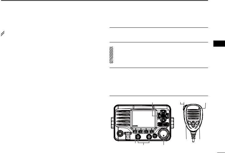
■■Front panel |
|
|
Speaker |
q Function display (p. 4) w e |
ENT |
r |
MENU CLEAR |
t |
|
y |
u
!1 !0 o i
q DISTRESS KEY [DISTRESS] (pp. 22, 23)
Hold down for 3 seconds to transmit a Distress call.
w ENTER KEY [ENT]
Push to set the input data, selected item, and so on.
e LEFT AND RIGHT KEYS [Ω]/[≈]
Push to switch to the previous or next key function that is assigned to the softkeys. (p. 7)
Push to select a desired character or number in the table while in the channel name, position, MMSI code, ATIS code programming mode, and so on. (pp. 8, 12, 21)
r UP AND DOWN/CHANNEL SELECT KEYS [∫CH]/[√CH]
Push to select the operating channels, Menu items, Menu settings, and so on.
While scanning, push to check Favorite channels, change the scanning direction or manually resume a scan. (p. 16)
t CLEAR KEY [CLEAR]
Push to cancel the entered data, or to return to the previous screen.
y MENU KEY [MENU]
Push to enter or exit the Menu screen. (p. 84)
u DIAL/POWER SWITCH [PWR]
When the power is OFF, hold down for 1 second to turn ON power.
Hold down for 1 second to turn OFF power.
Rotate to select the operating channels, Menu items, Menu settings, and so on.
Push to set the input data, selected item, and so on.
2

i CHANNEL 16/CALL CHANNEL KEY [16/C]
Push to select Channel 16. (p. 9)
Hold down for 1 second to select the Call channel. (p. 9)
• The “CALL” icon appears when the Call channel is selected.
o SQUELCH DIAL
Rotate to adjust the squelch level.
!0SOFTKEYS
Desired functions as described below can be assigned in the Menu screen. (p. 87)
Scan [ ]* (p. 16)
Push to start or stop a Normal or Priority scan.
*This key does not appear in Dutch version transceivers.
Dualwatch/Tri-watch [ ] (p. 17)
Push once to start and stop a Dualwatch or Tri-watch scan.
AIS [ ]* (p. 73)
Push to display the AIS plotter on the left side of the display.
*Some versions do not have an AIS receiver.
Channel [ ] (pp. 9, 11) Push to select a regular channel.
High/Low [ ] (p. 11)
Push to set the power to high or low.
• Some channels are set to only low power.
PANEL DESCRIPTION 2
Voice Scrambler [ ]* (p. 71)
Push to turn the Voice Scrambler ON or OFF.
• The “SBL” icon appears when the voice scrambler is ON.
*This key appears only when the voice scrambler unit is installed.
Voice Recorder [ ] (p. 71)
Push to playback recorded voice.
RX Hailer [ ] (p. 61)
Push to turn the RX Hailer mode ON or OFF.
LO/DX [ ]*
]*
Push to turn the Attenuator function ON or OFF.
• The “LOC” icon appears when the Attenuator function is ON. *This key appears only for Australian version transceivers.
Favorite channel [ ] (p. 16)
Push to set or clear the displayed channel as a Favorite (Tag) channel.
Hold down for 3 seconds to clear or set all Favorite (Tag) channels in the selected channel group.
Name [ ] (p. 12)
Push to enter the channel name entry mode.
Backlight [ ] (p. 14)
Push to enter the LCD and key backlight brightness adjustment mode.
Log [ ] (p. 58)
Push to enter “RCVD CALL LOG” in the DSC CALLS menu.
!1VOLUME DIAL
Rotate to adjust the volume level.
1
2
3
4
5
6
7
8
9
10
11
12
13
14
15
16
3

2 PANEL DESCRIPTION
■■Function display
|
q w e rt y ui o !0 |
@0 |
|
!9 |
|
!8 |
|
!7 |
!1 |
|
|
!6 |
!2 |
!5 |
!3 |
!4 |
|
q BUSY/TRANSMIT ICON (p. 11)
The “ ” icon appears when receiving a signal, or when the squelch is open.
The “ ” icon appears while transmitting.
w POWER ICON (p. 11)
The “25W” icon appears when high power is selected.The “1W” icon appears when low power is selected.
e RX HAILER ICON (p. 68)
Appears while in the RX Hailer mode.
r CHANNEL GROUP ICON (p. 10)
Shows which channel group is selected, a USA “USA” International “INT” ATIS “ATIS” or DSC “DSC”*, depending on the version.
*German transceiver version only
t CALL CHANNEL ICON (p. 9)
Appears when the Call channel is selected.
y DUPLEX ICON (p. 10)
Appears when a duplex channel is selected.
u FAVORITE CHANNEL ICON (p. 16)
Appears when a Favorite (Tag) channel is selected.
i MESSAGE ICON
Blinks when there is an unread DSC message.
o GPS ICON
Stays ON when the GPS receiver is activated and valid position data is received.
Blinks when invalid position data is being received.
!0SWITCH ICON (p. 62)
Appears when the “CH 16 SWITCH” in DSC Settings is set to OFF.
!1LOW BATTERY ICON
Blinks when the battery voltage drops to approximately 10.8 V DC or less.
!2CHANNEL NUMBER READOUT
Displays the selected operating channel number.
• When a simplex channel is selected, “A” or “B” appears.
!3CHANNEL NAME FIELD
The channel name appears, if entered. (p. 12)
4
!4KEY ICON (p. 6)
Displays the assigned function of the softkeys on the front panel.
!5TIME ZONE INDICATOR
Displays the current time when a GPS receiver is connected, or the time is manually entered.
•When the GPS current time is invalid, “??” will blink every 2 seconds instead of the current time. After 23.5 hours has passed, “NO TIME” will appear.
•“??” will blink every 2 seconds instead of the current time, after 4 hours have passed from when the time was manually entered. The manually programmed time is held for only 23.5 hours, and after that, “NO TIME” will appear.
“LOCAL” appears when the offset time is set.
“MNL” appears when the time is manually entered.
“UTC” appears when the GGA, GLL or GNS GPS sentence formats are included in the GPS signal.
The date information appears when the RMC GPS sentence formats are included in the GPS signal.
“NO TIME” appears when no GPS receiver is connected, and no time is manually entered.
!6POSITION INDICATOR
Shows the current position when a GPS receiver is connected, or the position is manually entered.
•When the GPS position is invalid, “??” may blink every 2 seconds instead of displaying the position. The last position is held for only 23.5 hours, and after that, “NO POSITION” will appear.
PANEL DESCRIPTION 2
•“??” will blink every 2 seconds instead of displaying the position, after 4 hours have passed from when the position is manually entered. The manually entered position is held for only 23.5 hours, and after that, “NO POSITION” will appear.
“NO POSITION” appears when no GPS receiver is connected, and no position is manually entered.
!7COURSE/SPEED INDICATOR
Shows the course and speed of your vessel if a GPS receiver is connected to the transceiver.
•Course and speed are displayed when the RMC GPS sentence format is included in the GPS signal.
Course and speed are also displayed when the VTG and either the GGA, GLL or GNS GPS sentence formats are included in the GPS signal.
!8SCAN INDICATOR
“SCAN 16” appears during a Priority scan, “SCAN” appears during a Normal scan. (p. 16)
“DUAL 16” appears during Dualwatch, “TRI 16” appears during Tri-watch. (p. 17)
!9LOCAL ICON
Appears when the Attenuator function is turned ON.
*This function is usable for only Australian version transceivers.
@0VOICE SCRAMBLER ICON* (p. 71)
Appears when the Voice Scrambler function is turned ON.
*Appears only when the voice scrambler unit is installed.
1
2
3
4
5
6
7
8
9
10
11
12
13
14
15
16
5

2 PANEL DESCRIPTION
■■Speaker Microphone
q |
Microphone |
|
|
|
Speaker |
w
r
e
q PTT SWITCH [PTT]
Hold down to transmit, release to receive. (p. 11)
w CHANNEL UP/DOWN KEYS [Y]/[Z]
Push either key to check Favorite channels, change scanning direction or manually resumes a scan. (pp. 11, 16)
• You can turn OFF the FAV on MIC setting (p. 93). After that, you can select all channels with these keys.
eTRANSMIT POWER KEY [H/L]
Push to toggle the power high or low. (p. 11)
• Some channels are set to only low power.
While holding down [H/L], turn ON the power to turn the Microphone Lock function ON or OFF. (p. 13)
r CHANNEL 16/CALL CHANNEL KEY [16/C]
Push to select Channel 16. (p. 9)
Hold down for 1 second to select the Call channel. (p. 9)
• The “CALL” icon appears when the Call channel is selected.
■■Softkey function
Various functions can be assigned to the softkeys. When a key function is assigned, the key icon is displayed above the softkey, as shown below.
DDSoftkey function selection
When “Ω” or “≈” is displayed beside the key icon, pushing [Ω]/ [≈] to scroll key functions that are assigned to the softkeys. The key movement is set to “Group” in default. 4 icons move by pushing [Ω]/[≈] once. You can set the key movement of your choice in menu screen. (p. 87)
Push
 Push this key to start and stop scan.
Push

 Push
Push
Push


 The order of the key icons may differ, depending on the
  transceiver version.
6

■■MMSI code entry
The 9 digit MMSI (Maritime Mobile Service Identity: DSC self ID) code can be entered at power ON.
 This initial code setting can be performed only once. After being set, it can be changed by only your dealer or distributor. If your MMSI code has already been en-
  tered, this procedure is not necessary.
qqHold down [PWR](Dial) to turn ON the power.
•Three short beeps sound, and “NO DSC MMSI” is displayed. wwPush [ENT] to start the MMSI code entry.
•Push [CLEAR] twice to cancel the entry, and go to the normal operating screen. In this case, the transceiver cannot make a DSC call. To enter the MMSI code, turn OFF the power, then turn it ON again.
eeEnter your MMSI code in the following manner:
•Select a desired number using [Y]/[Z]/[Ω]/[≈].
•Push [ENT] or dial to set it.
•To move the cursor, rotate dial or select either arrow, “←” or “→,” then push [ENT] or dial.
PREPARATION |
3 |
|
|
||
|
|
||||
|
|
||||
|
1 |
||||
|
|
|
|
|
|
|
|
|
|
|
|
rrRepeat step e to enter all 9 digits. |
|
|
2 |
||
|
|
3 |
|||
ttAfter entering the 9 digit code, “FINISH” is automatically |
|||||
selected, and then push [ENT] or dial to set it. |
|
|
4 |
||
yyThe “MMSI CONFIRMATION” screen is displayed. |
|
|
|||
|
|
5 |
|||
|
|
|
|
|
|
|
|
|
|
|
|
|
|
|
|
|
6 |
|
|
|
|
|
7 |
uuEnter your MMSI code again for confirmation. |
|
|
8 |
||
|
|
9 |
|||
• Enter in the same manner as steps e through t. |
|
|
|||
iiWhen your MMSI code entry is successfully completed, |
10 |
||||
the screen as shown below is briefly displayed. |
|
|
11 |
||
• After that, the normal operating screen is displayed. |
|
|
|||
|
|
|
|
|
12 |
|
|
|
|
|
|
|
|
|
|
|
13 |
|
|
|
|
|
14 |
|
|
|
|
|
15 |
|
|
|
|
|
16 |
|
|
|
|
|
|
The entered MMSI code can be checked in the MENU screen. (p. 85)
7
3 PREPARATION
■■ATIS code entry (For Dutch and German version transceivers)
The 10 digit ATIS (Automatic Transmitter Identification System) code can be entered at power ON.
 This initial code setting can be performed only once. After being set, it can be changed by only your dealer or distributor. If your ATIS code has already been en-
  tered, this procedure is not necessary.
qqPush [MENU].
wwRotate dial or push [Ω]/[≈] to select the “RADIO SET” icon and then push the softkey below the icon.
• The RADIO SETTINGS menu is displayed.
eeRotate dial or push [Y]/[Z] to select “CHAN Group,” and then push [ENT].
rrRotate dial or push [Y]/[Z] to select “ATIS,” and then push [ENT].
ttPush [BACK] twice.
yyRotate dial or push [Ω]/[≈] to select the “ATIS” icon and then push the softkey below the icon.
•ATIS code programming screen appears.
•Push [CLEAR] to cancel the programming, and go to the normal operating mode. In this case, the ATIS function is disabled. To program the ATIS code, repeat the steps q and y.
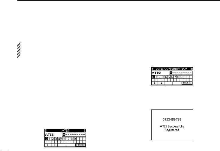
uuEnter your ATIS code in the following manner:
•Select a desired number using [∫]/[√]/[Ω]/[≈].
•Push [ENT] or Dial to set it.
•To move the cursor, rotate dial or select either arrow, “←” or “→,” then push [ENT] or dial.
iiRepeat step u to enter all 10 digits.
ooAfter entering the 10 digit code, “FINISH” is automatically selected, and then push [ENT] or Dial to set it.
!0The “ATIS CONFIRMATION” screen is displayed.
!1Enter your ATIS code again for confirmation.
• Enter in the same manner as steps u through o.
!2When your ATIS code entry is successfully completed, the screen as shown below is briefly displayed.
• After that, the normal operating screen is displayed.
The entered ATIS code can be checked in the MENU screen. (p. 85)
8

■■Channel selection
DDChannel 16
Channel 16 is the distress and safety channel. It is used for establishing initial contact with a station and for emergency communications.
While standing by, you must monitor Channel 16. Channel 16 is automatically monitored during both Dualwatch and Triwatch.
Push [16/C] to select Channel 16.
Push [CHAN] to return to the screen displayed before you selected Channel 16, or rotate dial or push [∫](CH)/[√](CH) to select an operating channel.
BASIC OPERATION |
4 |
|
|
|||||
|
|
|||||||
|
|
|||||||
|
1 |
|||||||
|
|
|
|
|
|
|
||
DDCall channel |
|
|
2 |
|||||
|
|
|
||||||
Each regular channel group has a separate leisure use Call |
3 |
|||||||
channel. The Call channels can be programmed, and are |
|
|||||||
4 |
||||||||
used to store your most often used channel in each channel |
||||||||
5 |
||||||||
group, for quick recall. |
|
|
||||||
The Call channel is monitored during Tri-watch. (p. 17) |
|
|
6 |
|||||
|
|
|
|
|
|
|
||
Hold down [16/C] for 1 second to select the Call channel of |
7 |
|||||||
the selected channel group. |
|
|
8 |
|||||
• The “CALL” icon and the Call channel number appear. |
|
|
||||||
• Each channel group has an independent call channel after pro- |
9 |
|||||||
gramming. (p. 12) |
|
|
||||||
|
|
10 |
||||||
Push [CHAN] to return to the screen displayed before you |
||||||||
selected Call channel, or rotate dial or push [∫](CH)/[√] |
11 |
|||||||
(CH) to select an operating channel. |
|
|
||||||
Appears |
|
|
|
|
|
|
12 |
|
|
|
|
|
|
|
|||
|
|
|
|
|
|
13 |
||
|
|
|
|
|
|
|
||
|
|
|
|
|
|
|
14 |
|
|
|
|
|
|
|
|
15 |
|
|
|
|
|
|
|
|
16 |
|
|
|
|
|
|
|
|
||
9
4 BASIC OPERATION
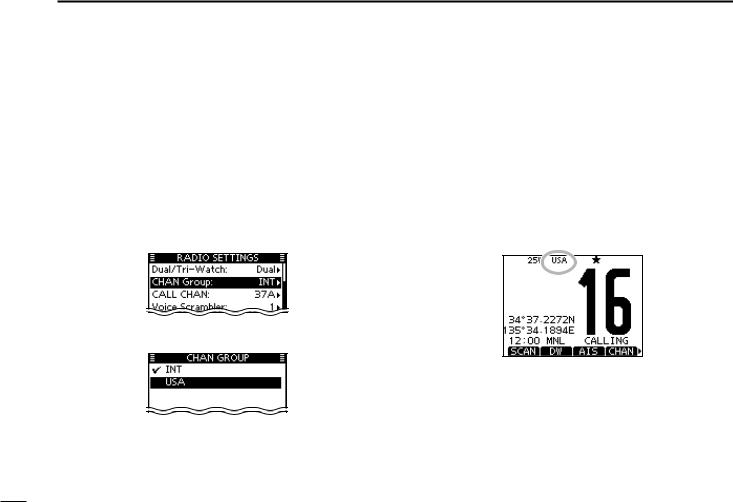
DDChannel group selection
There are preset international channels for the transceiver. Except for the Europe versions, you can select a channel group suitable for your operating area, as described below. q Push [MENU].
w Rotate dial or push [Ω]/[≈] to select the “RADIO SET” icon and then push the softkey below the icon.
• RADIO SETTINGS menu is displayed.
e Rotate dial or push [∫]/[√] to select “CHAN Group,” and then push [ENT].
r Rotate dial or push [∫]/[√] to select the desired channel group, and then push [ENT].
t Push [EXIT] to exit the Menu screen.
y Rotate dial or push [∫](CH)/[√](CH) to select a channel.
•Pushing [Y]/[Z] on the microphone selects only Favorite channels.
• You can turn OFF the FAV on MIC setting (p. 93). After that, you can select all channels by using the microphone.
•The “DUP” icon appears when a duplex channel is selected.
•“A” appears when a simplex channel is selected.
Channel group icon appears
When the USA channel group is selected.
10
■■Receiving and transmitting
 CAUTION: Transmitting without an antenna will damage
  the transceiver.
qqHold down [PWR](Dial) to turn ON the power. wwSet the audio and squelch levels. (p. 3)
First, open the squelch. Then, adjust the audio output level. After that, adjust the squelch level until the noise just disappears.
eeChange the channel group. (p. 10)
rrRotate dial or push [∫](CH)/[√](CH) to select a channel. (pp. 9, 10)
•Pushing [Y]/[Z] on the microphone selects only Favorite channels.
• You can turn OFF the FAV on MIC setting (p. 93). After that, you can select all channels using the microphone.
• When receiving a signal, the “ ” icon appears and audio is heard.
•Further adjustment of the volume level may be necessary. ttPush [HI/LO] to select the output power, if necessary.
•The “25W” icon appears when high power is selected, and the “1W” icon appears when low power is selected.
•Choose low power for short range communications, choose high power for longer distance communications.
•Some channels are for only low power.
yyHold down [PTT] to transmit, then speak at your normal voice level.
• The “ ” icon appears.
• Channel 70 cannot be used for transmission other than DSC.
BASIC OPERATION 4
uuRelease [PTT] to receive.
Information |
|
|
2 |
|
The Noise Cancel function reduces random noise components |
3 |
|||
in the transmit and/or receive signal. See page 92 for details. |
||||
4 |
||||
IMPORTANT: To maximize the readability of your transmit- |
||||
5 |
||||
ted signal, pause a few seconds after pushing [PTT], hold |
||||
6 |
||||
the microphone 5 to 10 cm from your mouth and speak at |
||||
your normal voice level. |
|
|
7 |
|
|
|
|
||
NOTE for the TOT (Time-out Timer) function |
|
8 |
||
The TOT function inhibits continuous transmission beyond a |
9 |
|||
preset time period after the transmission starts. |
|
|||
A beep sounds 10 seconds before transmission is cutoff to |
10 |
|||
indicate the transmission will be shut down, and “TOT” appears |
11 |
|||
in the channel name field. |
|
|
||
r |
yu |
Microphone |
12 |
|
|
|
|
13 |
|
|
CH |
|
14 |
|
|
ENT |
|
|
|
|
|
|
15 |
|
|
MENU CLEAR |
|
16 |
|
|
|
|
||
|
t |
r |
|
|
t w |
q |
11
4 BASIC OPERATION
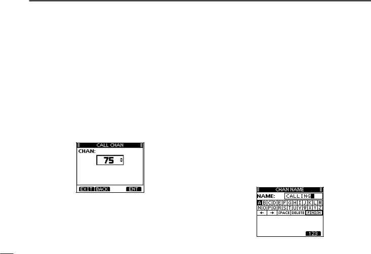
■■Call channel entry
You can enter the Call channel with your most often-used channel in each channel group for quick recall.
qqSelect the desired channel group (INT, USA, CAN or ATIS) to be entered. (p. 10)
w Push [MENU].
e Rotate dial or push [Ω]/[≈] to select the “RADIO SET” icon and then push the softkey below the icon.
• RADIO SETTINGS menu is displayed.
r Rotate dial or push [∫]/[√] to select “CALL CHAN,” and then push [ENT].
t Rotate dial or push [∫](CH)/[√](CH) to select a channel.
y Push [ENT] to save the channel as the Call channel.
• Push [BACK] to cancel and return to the previous screen. uuPush [EXIT] to exit the Menu screen.
■■Channel name entry
Each channel can be assigned a unique alphanumeric ID of up to 10 characters.
Capital letters, 0 to 9, some symbols (! " # $ % & ' ( ) * + , – . / [ \ ] ^ _ : ; < = > ?) and a space can be input.
qqRotate dial or push [∫](CH)/[√](CH) to select a channel.
• First, cancel the Dualwatch, Tri-watch or Scan function, if activated.
wwPush [NAME] to open the channel name entry screen.
• A cursor is displayed on the first character.
eeEnter the desired channel name in the following manner:
•Select a desired character using [∫]/[√]/[Ω]/[≈].
•Push [ENT] or dial to set it.
•To move the cursor, rotate dial or select either arrow, “←” or “→,” then push [ENT] or dial.
•Push [123], [!$?] or [ABC] to select a character group.
•Select “SPACE,” then push [ENT] to enter a space.
•Select “DELETE,” then push [ENT] to delete a character.
•Push [CLEAR] to cancel and return to the previous screen.
12

rrRepeat step e to enter all characters.
t Push [Ω]/[≈]/[∫]/[√] to select “FINISH,” then push [ENT] to set the name and return to the previous screen.
BASIC OPERATION 4
■■Microphone Lock function
The Microphone Lock function electrically locks [∫], [√], [16/C] and the [H/L] keys on the supplied microphone. This prevents accidental channel changes or function access.
While holding down [H/L] on the microphone, hold down [PWR](Dial) to turn ON the transceiver and turn the Microphone Lock function ON or OFF.
[H/L] |
[16/C] |
|
[Y]/[Z] |
||
|
1
2
3
4
5
6
7
8
9
10
11
12
13
14
15
16
13
4 BASIC OPERATION
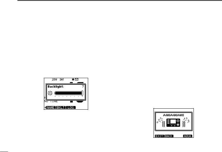
■■Adjusting the Backlight level
The function display and keys can be backlit for better visibility under low light conditions.
The backlight is adjustable in 7 levels, and OFF.
Depending on the presetting, the adjustment method differs, as described below.
Push [BKLT] to show the backlight adjustment screen. Rotate dial or push [∫]/[√]/[Ω]/[≈] to adjust the brightness of the LCD and key backlight, and then, push [ENT].
•If no key operation is performed for about 5 seconds, the transceiver sets the selected backlight level, and returns to the normal mode.
■■AquaQuake water draining function
The AquaQuake water draining function clears water away from the speaker grill. Without this function, water may muffle the sound coming from the speaker. A buzzing sound is heard when this function is activated.
q Push [MENU].
w Rotate dial or push [Ω]/[≈] to select the “AQUA QUAKE,” icon and then push the softkey below the icon.
• AQUAQUAKE screen is displayed.
While holding down [AQUA], the AquaQuake function is activated to clear water away from the speaker grill.
•While holding down [AQUA], a low buzzing sounds to drain water, regardless of the volume level setting.
•The transceiver keys, except [DISTRESS], are disabled while the AquaQuake function is activated.
When the AquaQuake function is activated.
14
■■Scan types
Scanning is an efficient way to locate signals quickly over a wide frequency range. The transceiver has a Priority scan and a Normal scan.
PRIORITY SCAN
CH 01 |
|
CH 02 |
CH 88 |
CH 16 |
CH 03 |
CH 05 |
|
CH 04 |
The Priority scan sequentially searches through all Favorite channels while monitoring Channel 16. When a signal is detected on Channel 16, the scan pauses until the signal disappears. When a signal is detected on a channel other than Channel 16, the scan becomes a Dualwatch until the signal disappears.
SCAN OPERATION |
5 |
|
|
||
|
|
||||
|
|
||||
|
1 |
||||
|
|
|
|
||
Set the Favorite channels (scanned channel) before scan- |
2 |
||||
3 |
|||||
ning. Clear the Favorite channels which inconveniently stop |
|||||
scanning, such as those for digital communication use. (Refer |
|
||||
4 |
|||||
to the next page for details.) |
|
|
|
||
|
|
|
|
||
Choose Priority or Normal scan in the Menu screen. (p. 90) |
5 |
||||
6 |
|||||
|
|
|
|
||
NORMAL SCAN |
|
|
|
7 |
|
CH 01 |
CH 02 |
|
|
8 |
|
|
|
9 |
|||
|
|
|
|
||
|
|
|
|
10 |
|
CH 88 |
|
CH 03 |
|
11 |
|
|
|
|
|
12 |
|
CH 05 |
CH 04 |
|
|
13 |
|
|
|
14 |
|||
|
|
|
|
||
The Normal scan, like the Priority scan, sequentially |
|
15 |
|||
searches through all Favorite channels. However, unlike |
|
16 |
|||
the Priority scan, Channel 16 is not checked unless it is set |
|
|
|||
as a Favorite channel. |
|
|
|
|
|
|
|
|
|
|
|
15
5 SCAN OPERATION
■■Setting Favorite channels
For more efficient scanning, add desired channels as Favorite channels, or clear the Favorite on unwanted channels. Channels that are not tagged as Favorites will be skipped while scanning. Favorite channels can be independently assigned to each channel group (INT, USA, CAN or ATIS).
qqSelect the desired channel group. (p. 10)
wwSelect the desired channel to be set as a Favorite channel. eePush [] to set the displayed channel as a Favorite channel.
• The “” icon appears on the display.
rrTo cancel the Favorite channel setting, repeat step e.
• The “” icon disappears.
Clearing (or setting) all Favorite channels
Hold down [] for 3 seconds (until a long beep changes to 2 short beeps) to clear all Favorite channel settings in the selected channel group.
• Repeat above procedure to set all channels as Favorite channels.
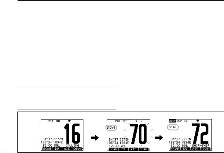
■■Starting a scan
First, set the scan type (Priority or Normal scan) and scan resume timer in the Menu screen. (p. 90)
qqSelect the desired channel group. (p. 10)
wwSet the Favorite channels, as described to the left. eeMake sure the squelch is closed to start a scan. rrPush [SCAN] to start a Priority or Normal scan.
•“SCAN 16” appears during a Priority scan; “SCAN” appears during a Normal scan.
•When a signal is detected, the scan pauses until the signal disappears, or resumes after pausing 5 seconds, depending on the setting. (Channel 16 is still monitored during a Priority scan.)
•Push [Y]/[Z] on either transceiver or microphone, to check the scanning Favorite channels, change the scanning direction or manually resume the scan.
•A beep tone sounds and “16” blinks when a signal is received on Channel 16 during a Priority scan.
ttTo stop the scan, push [CLEAR] or repeat step r.
[Example]: Starting a Normal scan. |
Scan starts. |
When a signal is received. |
|
Push |
|
|
[SCAN] |
|
16

DUALWATCH/TRI-WATCH 6 
■■Description
Dualwatch monitors Channel 16 while you are receiving on another channel; Tri-watch monitors Channel 16 and the Call channel while receiving another channel. Dualwatch and Tri-watch are convenient for monitoring Channel 16 when you are operating on another channel.
DUALWATCH/TRI-WATCH SIMULATION
Call channel
Ch 16 |
Ch 88 |
Ch 88 |
Ch 16 |
Ch 88 |
Ch 75 |
Dualwatch |
Tri-watch |
• If a signal is received on Channel 16, Dualwatch and Triwatch pause on Channel 16 until the signal disappears.
• If a signal is received on the Call channel during Tri-watch, Tri-watch becomes Dualwatch until the signal disappears.
• To transmit on the selected channel during a Dualwatch or Tri-watch, hold down [PTT].
■■Operation
qqSelect Dualwatch or Tri-watch in the Menu screen. (p. 90) wwRotate dial or push [Y](CH)/[Z](CH) to select the desired
operating channel.
eePush [DW] to start a Dualwatch or Tri-watch scan.
•“DUAL 16” appears during Dualwatch; “TRI 16” appears during Tri-watch.
• A beep tone sounds when a signal is received on Channel 16. rrTo cancel Dualwatch or Tri-watch, push [DW] again.
[Example]: Operating Tri-watch on INT Channel 25.
|
|
|
|
Signal is received on |
|
Tri-watch starts. |
|
Call channel. |
|||
|
|
|
|
|
|
|
|
|
|
|
|
|
|
|
|
|
|
Tri-watch resumes after the |
|
Signal received on Channel |
||||
signal disappears. |
|
16 takes priority. |
||||
|
|
|
|
|
|
|
|
|
|
|
|
|
|
|
|
|
|
|
|
|
1
2
3
4
5
6
7
8
9
10
11
12
13
14
15
16
17
 7 DSC OPERATION
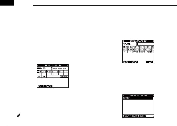
■■DSC address ID
DDEntering an Individual ID
A total of 100 DSC address IDs can be entered and assigned a name of up to 10 characters.
qqSelect “INDIVIDUAL ID” in the DSC SETTINGS menu.
MENU |
DSC SET |
Individual ID |
(Push [MENU]) |
(Select icon) |
(Rotate dial, then push [ENT].) |
wwPush [ADD].
• The “INDIVIDUAL ID” program screen is displayed.
eeEnter a desired individual ID in the following way:
•Select a desired number using [Y]/[Z]/[Ω]/[≈].
•Push [ENT] or dial to set it.
•To move the cursor, rotate dial or select either arrow, “←” or “→,” then push [ENT] or dial.
•Push [EXIT] to return to the normal operating mode.
•Push [BACK] to return to the previous screen.
 The first digit is ‘0,’ and the second digit is other than ‘0’
 for a Group ID.
The first two digits are ‘0’ for any Coast station ID. r Repeat step e to enter all 9 digits.
ttAfter entering the 9 digit code, push [ENT] or dial to set it.
• The ID name entry screen is displayed.
yyEnter a desired 10 digit ID name in the following way:
•Select a desired character using [Y]/[Z]/[Ω]/[≈].
•Push [ENT] or dial to set it.
•To move the cursor, rotate dial or select either arrow, “←” or “→,” then push [ENT] or dial.
•Push [123], [!$?] or [ABC] to select a character group.
uuAfter entering the ID name, select “FINISH” using [Y]/[Z]/ [Ω]/[≈], then push [ENT] to program it.
• The “INDIVIDUAL ID” list screen is displayed.
iiPush [MENU] to exit the MENU screen.
18
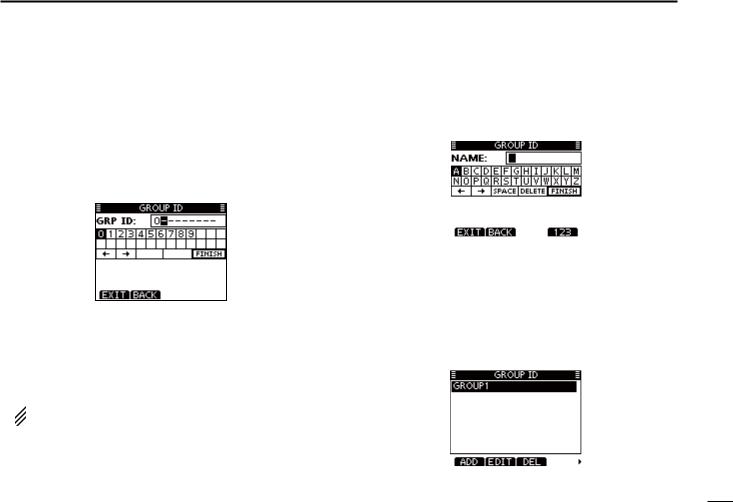
D Entering a Group ID
qqSelect “GROUP ID” in the DSC SETTINGS menu.
MENU |
DSC SET |
Group ID |
(Push [MENU]) |
(Select icon) |
(Rotate dial, then push [ENT].) |
wwPush [ADD].
• The “GROUP ID” program screen is displayed.
e Enter a desired group ID in the following way:
•Select a desired number using [Y]/[Z]/[Ω]/[≈].
•Push [ENT] or dial to set it.
•To move the cursor, rotate dial or select either arrow, “←” or “→,” then push [ENT] or dial.
•Push [EXIT] to return to the normal operating mode.
•Push [BACK] to return to the previous screen.
 The first digit is fixed as ‘0’ for a Group ID.
 The first two digits are ‘0’ for any Coast station ID.
r Repeat step e to enter the specific 9 digits group code.
DSC OPERATION 7
|
|
|
1 |
|
|
|
|
2 |
|
t After entering the 9 digit code, push [ENT] or dial to set it. |
3 |
|||
• The Group ID name entry screen is displayed. |
4 |
|||
|
|
|
||
|
|
|
||
|
|
|
5 |
|
|
|
|
6 |
|
|
|
|
|
|
|
|
|
7 |
|
|
|
|
8 |
|
yyEnter a desired 10 digit ID name in the following way: |
||||
9 |
||||
• Select a desired character using [Y]/[Z]/[Ω]/[≈]. |
||||
10 |
||||
• Push [ENT] or dial to set it. |
||||
• To move the cursor, rotate dial or select either arrow, “←” or “→,” |
11 |
|||
then push [ENT] or dial. |
||||
• Push [123], [!$?] or [ABC] to select a character group. |
12 |
|||
uuAfter entering the ID name, select “FINISH” using [Y]/[Z]/ |
||||
13 |
||||
[Ω]/[≈], then push [ENT] or dial to program it. |
||||
• The “GROUP ID” list screen is displayed. |
14 |
|||
|
|
|
||
|
|
|
||
|
|
|
15 |
|
|
|
|
16 |
|
|
|
|
|
|
i Push [MENU] to exit the MENU screen. |
|
|||
19

7 DSC OPERATION
D Deleting Individual/Group ID
q Select “INDIVIDUAL ID” or “GROUP ID” in the DSC SETTINGS menu.
MENU |
DSC SET |
Individual ID / Group ID |
(Push [MENU]) |
(Select icon) |
(Rotate Dial, then push [ENT].) |
•When no address ID is entered, “No ID” is displayed. In this case, push [MENU] to exit the MENU screen.
w Rotate dial or push [Y]/[Z] to select a desired ID name, then push [DEL].
e Push [OK] to delete the ID, and return to the “INDIVIDUAL ID” or “GROUP ID” list screen.
• Push [CANCEL] to cancel it.
r Push [MENU] to exit the MENU screen.
20
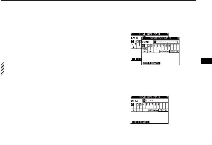
■■Position and time entry
A Distress call should include the ship’s position and time. If no GPS is connected, your position and UTC (Universal Time Coordinated) time should be manually entered. They are automatically included when a GPS receiver compatible with the NMEA 0183 (ver. 2.0 or later) or NMEA 2000* format is connected.
*Some versions do not have a NMEA 2000 connector.
 • Manual entry is disabled when a GPS receiver is connected.
• Manually entered position and time will be held for only  23.5 hours.
q Select “POSITION INPUT” in the DSC SETTINGS menu. wwEdit your latitude and longitude position using dial, and
MENU |
DSC SET |
Position Input |
(Push [MENU]) |
(Select icon) |
(Rotate dial, then push [ENT].) |
[Y]/[Z]/[Ω]/[≈].
•Select a desired number using [Y]/[Z]/[Ω]/[≈].
•Push [ENT] or dial to set it.
•To move the cursor, rotate dial or select either arrow, “←” or “→,” then push [ENT] or dial.
•Select N (North latitude) or S (South latitude) when the cursor is on the ‘N’ or ‘S’ position.
•Select W (West longitude) or E (East longitude) when the cursor is on the ‘W’ or ‘E’ position.
DSC OPERATION 7
eeAfter entering the position, push [ENT] to program it. rrThe UTC time entry screen is displayed, enter the UTC
time in the following way:
•Select a desired number using [Y]/[Z]/[Ω]/[≈].
•Push [ENT] or dial to set it.
•To move the cursor, rotate dial or select either arrow, “←” or “→,” then push [ENT] or dial.
ttPush [ENT] or dial to set your position and time.
• Return to the “DSC SETTINGS” screen.
1
2
3
4
5
6
7
8
9
10
11
12
13
14
15
16
21
7 DSC OPERATION
■■Distress call
A Distress call should be transmitted if, in the opinion of the Master, the ship or a person is in distress and requires immediate assistance.
 NEVER MAKE A DISTRESS CALL IF YOUR SHIP OR A PERSON IS NOT IN AN EMERGENCY. A DISTRESS CALL SHOULD BE MADE ONLY WHEN IMMEDIATE
  HELP IS NEEDED.
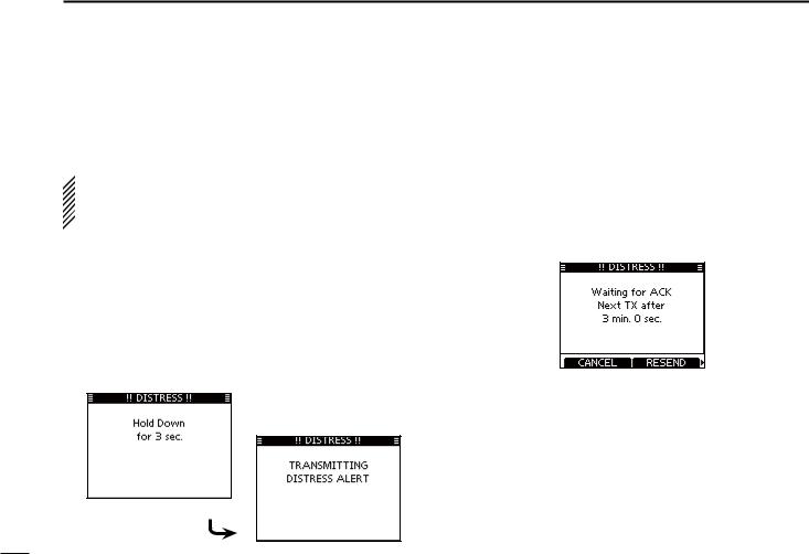
DDSimple call
qqWhile lifting up the key cover, hold down [DISTRESS] for 3 seconds to transmit the Distress alert.
•While holding down [DISTRESS], count down beeps sound and both the key and display backlighting blink.
•DSC channel (Channel 70) is automatically selected and the Distress alert is transmitted.
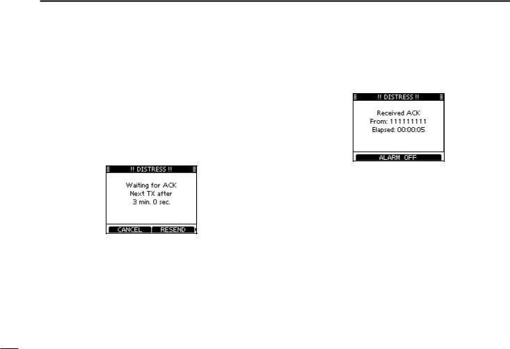
wwAfter transmitting the alert, the transceiver waits for an acknowledgment call.
•The Distress alert is automatically transmitted every 3.5 to 4.5 minutes, until an acknowledgement is received (‘Call repeat’ mode), or a DSC Cancel call is made. (p. 27)
•Push [RESEND] to manually transmit the Distress repeat alert.
•Push [Ω]/[≈] then push [INFO] to display the transmitted Distress call information.
•Push [Ω]/[≈] then push [PAUSE] to pause the ‘Call repeat’ mode, push [RESUME COUNTDOWN] to resume it.
eeAfter receiving the acknowledgment, push [ALARM OFF] then reply using the microphone.
A distress alert default contains:
• Nature of distress: Undesignated distress
• Position information: The latest GPS or manual input position is held for 23.5 hours, or until the power is turned OFF.
22
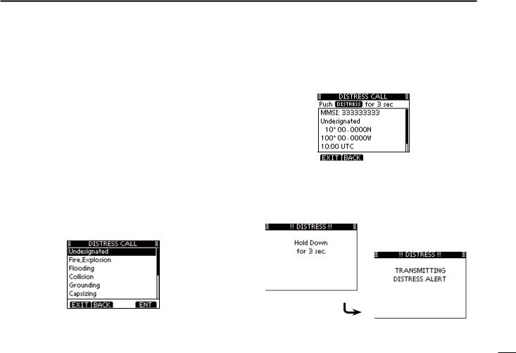
D Regular call
The nature of the Distress call should be included in the Distress call.
qqSelect “DISTRESS CALL” in the DSC menu.
MENU |
DSC |
Distress Call |
(Push [MENU]) |
(Select icon) |
(Rotate dial, then push [ENT].) |
w Select the nature of the distress using dial or [Y]/[Z], then push dial or [ENT].
• ‘Undesignated,’‘Fire,Explosion,’‘Flooding,’‘Collision,’‘Grounding,’ ‘Capsizing,’ ‘Sinking,’ ‘Adrift,’ ‘Abandoning ship,’ ‘Piracy’ or ‘Man Overboard’ is selectable.
• The nature of the distress is stored for 30 seconds after a selection is made.
•Push [EXIT] to return to the normal operating mode.
•Push [BACK] to return to the previous screen.
DSC OPERATION 7
|
|
|
|
|
|
|
1 |
|
e The Distress call confirmation screen is displayed. |
2 |
|||||||
• Rotate dial or push [Y]/[Z] to see the hidden lines. |
3 |
|||||||
|
|
|
|
|
|
|
||
|
|
|
|
|
|
|
4 |
|
|
|
|
|
|
|
|
||
|
|
|
|
|
|
|
5 |
|
|
|
|
|
|
|
|
6 |
|
|
|
|
|
|
|
|
|
|
|
|
|
|
|
|
|
7 |
|
|
|
|
|
|
|
|
8 |
|
r Hold down [DISTRESS] for 3 seconds to transmit the Dis- |
||||||||
9 |
||||||||
tress alert. |
||||||||
10 |
||||||||
• While holding down [DISTRESS], count down beeps sound and |
||||||||
|
both the key and display backlighting blink. |
11 |
||||||
• The selected nature of the distress is stored for 30 seconds. |
||||||||
|
|
|
|
|
|
|
12 |
|
|
|
|
|
|
|
|
||
|
|
|
|
|
|
|
13 |
|
|
|
|
|
|
|
|
14 |
|
|
|
|
|
|
|
|
15 |
|
|
|
|
|
|
|
|
16 |
|
|
|
|
|
|
|
|
||
|
|
|
|
|
|
|
|
|
+ Continued on the next page.
23
7 DSC OPERATION
D Regular call (continued)
t After transmitting the alert, the transceiver waits for an acknowledgment call.
•The Distress alert is automatically transmitted every 3.5 to 4.5 minutes, until an acknowledgement is received (‘Call repeat’ mode), or DSC cancel call is made. (p. 26)
•Push [RESEND] to manually transmit the Distress repeat alert.
•Push [Ω]/[≈] then push [INFO] to display the transmitted Distress call information.
•Push [Ω]/[≈] then push [PAUSE] to pause the ‘Call repeat’ mode, push [RESUME COUNTDOWN] to resume it.
y After receiving an acknowledgment call, push [ALARM OFF] then reply using the microphone.
A distress alert contains:
• Nature of distress: Selected in step w.
• Position information: The latest GPS or manual input position is held for 23.5 hours, or until the power is turned OFF.
24
Loading...