


INSTRUCTION MANUAL
VHF MARINE TRANSCEIVER
iM505
FOREWORD
Thank you for purchasing this Icom product. The IC-M505 VHF MARINE TRANSCEIVER is designed and built with Icom’s state of the art technology and craftsmanship. With proper care, this product should provide you with years of troublefree operation.
We want to take a couple of moments of your time to thank you for making the IC-M505 your radio of choice, and hope you agree with Icom’s philosophy of “technology first.” Many hours of research and development went into the design of your IC-M505.
D FEATURES
Simple operation with large keys
Easy to hear speaker
Built-in DSC meets ITU Class D requirement
Rugged waterproof construction
Optional COMMANDMIC III™ (HM-162E) is available
Icom, Icom Inc. and the 
 logo are registered trademarks of Icom Incorporated (Japan) in the United States, the United Kingdom, Germany, France, Spain, Russia and/or other countries.
COMMANDMIC III is a trademark of Icom Incorporated (Japan) in the United States.
IMPORTANT
READ ALL INSTRUCTIONS carefully and completely before using the transceiver.
SAVE THIS INSTRUCTION MANUAL — This instruction manual contains important operating instructions for the IC-M505.
EXPLICIT DEFINITIONS
WORD |
DEFINITION |
Personal injury, fire hazard or electric shock R WARNING! may occur.
CAUTION Equipment damage may occur.
NOTE
Recommended for optimum use. No risk of personal injury, fire or electric shock.
CLEAN THE TRANSCEIVER AND MICROPHONE THOROUGHLY WITH FRESH WATER after exposure to water including salt, otherwise, the keys and switch may become inoperable due to salt crystallization.
i

IN CASE OF EMERGENCY
If your vessel requires assistance, contact other vessels and the Coast Guard by sending a Distress call on Channel 16.
USING CHANNEL 16
DISTRESS CALL PROCEDURE
1.“MAYDAY MAYDAY MAYDAY.”
2.“THIS IS ...............” (name of vessel).
3.Say your call sign or other indication of the vessel (AND 9-digit DSC ID if you have one).
4.“LOCATED AT ...............” (your position).
5.State the nature of the distress and assistance required.
6.Give any other information which might facilitate the rescue.
Or, transmit your Distress call using digital selective calling on Channel 70.
USING DIGITAL SELECTIVE CALLING (Ch 70)
DISTRESS CALL PROCEDURE
1.While lifting up the key cover, push and hold [DISTRESS] for 5 sec. until you hear 5 short beeps change to one long beep.
2.Wait for an acknowledgment on Channel 70 from a coast station.
•After the acknowledgement is received, Channel 16 is automatically selected.
3.Push and hold [PTT], then transmit the appropriate information as listed above.
INSTALLATION NOTE
The installation of this equipment should be made in such a manner as to respect the EC recommended electromagnetic field exposure limits (1999/519/EC).
The maximum RF power available from this device is 25 watts. The antenna should be installed as high as possible for maximum efficiency and that this installation height should be at least 5 meters above ground (or accessible) level. In the case where an antenna cannot be installed at a reasonable height, then the transmitter should neither be continuously operated for long periods if any person is within 5 meters of the antenna, nor operated at all if any person is touching the antenna.
In all cases any possible risk depends on the transmitter being activated for long periods. (actual recommendation limits are specified as an average of 6 minutes) Normally the transmitter is not active for long periods of time. Some radio licenses will require that a timer circuit automatically cuts the transmitter after 1–2 minutes etc.
Similarly some types of transmitter, SSB, CW, AM, etc. have a lower ‘average’ output power and the perceived risk is even lower.
ii
DOC
CE versions of the IC-M505 which display the “CE” symbol on the serial number seal, comply with the essential requirements of the European Radio and Telecommunication Terminal Directive 1999/5/EC.
This warning symbol indicates that this equipment operates in non-harmonised frequency bands and/or may be subject to licensing conditions in the country of use. Be sure to check that you have the correct version of this radio or the correct programming of this radio, to comply with national licensing requirement.
DECLARATION OF CONFORMITY
We Icom Inc. Japan
1-1-32, Kamiminami, Hirano-ku
Osaka 547-0003, Japan
Declare on our sole responsibility that this equipment complies with the essential requirements of the Radio and Telecommunications Terminal Equipment Directive, 1999/5/EC, and that any applicable Essential Test Suite measurements have been performed.
Kind of equipment: VHF MARINE TRANSCEIVER
Type-designation: iM505
Version (where applicable):
This compliances is based on conformity with the following harmonised standards, specifications or documents:
i) |
EN 301 025-2 |
V1.2.1 (2004-09) |
ii) |
EN 301 025-3 |
V1.2.1 (2004-09) |
iii) |
EN 60945 |
2002 |
iv) |
EN 60950-1 |
2001 |
v) |
EN 300 698-2 |
V1.1.1 ( 2000-08) |
vi) |
EN 300 698-3 |
V1.1.1 ( 2001-05) |

 0560
0560


 28th Feb. 2006
Place and date of issue
Authorized representative name
Signature
iii

TABLE OF CONTENTS
FOREWORD …………………………………………………………… i IMPORTANT …………………………………………………………… i EXPLICIT DEFINITIONS ……………………………………………… i IN CASE OF EMERGENCY…………………………………………… ii INSTALLATION NOTE ………………………………………………… ii DOC …………………………………………………………………… iii TABLE OF CONTENTS ……………………………………………… iv
PRECAUTIONS ………………………………………………………… v
1OPERATING RULES ……………………………………………… 1
2PANEL DESCRIPTION ………………………………………… 2–5
■Front panel ……………………………………………………… 2
■Function display ………………………………………………… 4
■Microphone ……………………………………………………… 5
3BASIC OPERATION…………………………………………… 6–11
■Channel selection ……………………………………………… 6
■Receiving and transmitting……………………………………… 8
■Call channel programming ……………………………………… 9
■Channel comments …………………………………………… 10
■Microphone Lock function …………………………………… 10
■Display backlight ……………………………………………… 10
■ Optional voice scrambler operation ………………………… 11
4SCAN OPERATION ………………………………………… 12–13
■Scan types ……………………………………………………… 12
■Setting TAG channels ………………………………………… 13
■Starting a scan ………………………………………………… 13
5DUALWATCH/TRI-WATCH ……………………………………… 14
■Description ……………………………………………………… 14
■Operation ……………………………………………………… 14
6DSC OPERATION …………………………………………… 15–49
■MMSI code programming……………………………………… 15
■MMSI code check ……………………………………………… 16
■DSC address ID………………………………………………… 17
■Position and time programming ……………………………… 21
■Position and time indication …………………………………… 22
■GPS information indication …………………………………… 22
■Distress call …………………………………………………… 23
■Transmitting DSC calls ………………………………………… 26
■Receiving DSC calls …………………………………………… 41
■Received messages …………………………………………… 45
■DSC Set mode ………………………………………………… 47
7 OTHER FUNCTIONS………………………………………… 50–54
■Intercom operation …………………………………………… 50
■RX Speaker function …………………………………………… 51
■Hailer operation ………………………………………………… 52
■Automatic foghorn function …………………………………… 53
8 SET MODE …………………………………………………… 55–57
■Set mode programming ……………………………………… 55
■Set mode items ………………………………………………… 55
9 CONNECTIONS AND MAINTENANCE …………………… 58–64
■Connections …………………………………………………… 58
■Antenna ………………………………………………………… 59
■Fuse replacement ……………………………………………… 59
■Supplied accessories ………………………………………… 59
■Microphone hanger …………………………………………… 59
■Mounting the transceiver ……………………………………… 60
■MB-75 installation ……………………………………………… 61
■UT-112/UT-98 installation ……………………………………… 62
■HM-162E installation…………………………………………… 63
10 TROUBLESHOOTING …………………………………………… 66
11 SPECIFICATIONS AND OPTIONS ……………………… 67–68
■Specifications …………………………………………………… 67
■Options ………………………………………………………… 68
12 CHANNEL LIST ……………………………………………… 69–70 TEMPLATE
1
2
3
4
5
6
7
8
9
10
11
12
iv

PRECAUTIONS
RWARNING! NEVER connect the transceiver to an AC outlet. This may pose a fire hazard or result in an electric shock.
NEVER connect the transceiver to a power source of more than 16 V DC or use reverse polarity. This will ruin the transceiver.
NEVER cut the DC power cable between the DC plug at the back of the transceiver and fuse holder. If an incorrect connection is made after cutting, the transceiver may be damaged.
NEVER place the transceiver where normal operation of the vessel may be hindered or where it could cause bodily injury.
KEEP the transceiver at least 1 m away from the ship’s navigation compass.
DO NOT use or place the transceiver in areas with temperatures below –20°C or above +60°C or, in areas subject to direct sunlight, such as the dashboard.
AVOID the use of chemical agents such as benzine or alcohol when cleaning, as they may damage the transceiver surfaces. If the transceiver becomes dusty or dirty, wipe it clean with a soft, dry cloth.
BE CAREFUL! The transceiver rear panel will become hot when operating continuously for long periods.
Place the transceiver in a secure place to avoid inadvertent use by children.
BE CAREFUL! The transceiver and the optional HM162E COMMANDMIC III™ employ waterproof construction, which corresponds to IPX8 of the international standard IEC 60529 (2001). However, once the transceiver or microphone has been dropped, waterproofing cannot be guaranteed due to the fact that the case may be cracked, or the waterproof seal damaged, etc.
v

DPRIORITIES
•Read all rules and regulations pertaining to priorities and keep an up-to-date copy handy. Safety and Distress calls take priority over all others.
•You must monitor Channel 16 when you are not operating on another channel.
•False or fraudulent distress signals are prohibited and punishable by law.
DPRIVACY
•Information overheard but not intended for you cannot lawfully be used in any way.
•Indecent or profane language is prohibited.
DRADIO LICENSES
(1) SHIP STATION LICENSE
You must have a current radio station license before using the transceiver. It is unlawful to operate a ship station which is not licensed.
Inquire through your dealer or the appropriate government agency for a Ship-Radiotelephone license application. This government-issued license states the call sign which is your craft’s identification for radio purposes.
OPERATING RULES |
1 |
|
|
|
|
|
|||
|
|
|||
|
|
|||
(2) OPERATOR’S LICENSE |
|
|
|
|
|
|
1 |
||
A Restricted Radiotelephone Operator Permit is the license |
||||
|
||||
most often held by small vessel radio operators when a radio |
||||
is not required for safety purposes. |
|
|
|
|
The Restricted Radiotelephone Operator Permit must be posted or kept with the operator. Only a licensed radio operator may operate a transceiver.
However, non-licensed individuals may talk over a transceiver if a licensed operator starts, supervises, ends the call and makes the necessary log entries.
Keep a copy of the current government rules and regulations handy.
1
 2 PANEL DESCRIPTION
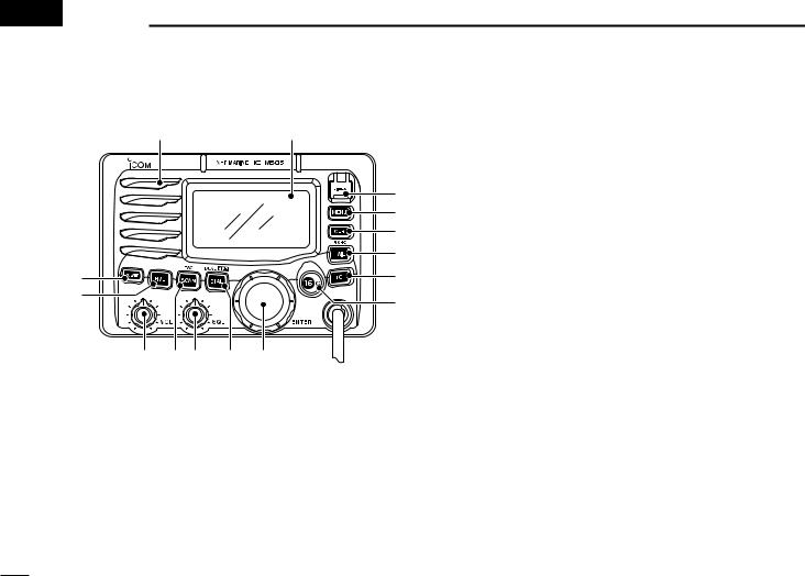
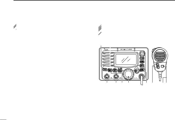
■ Front panel
Speaker |
Function display (p. 4) |
q w e
|
r |
!3 |
t |
!2 |
y |
|
!1 !0 o i u
qDISTRESS KEY [DISTRESS]
Push for 5 sec. to transmit a Distress call. (p. 23)
wDSC MENU KEY [MENU]
Push to toggle the DSC menu appear or disappear. (p. 15)
eCLEAR KEY [CLR]
Push to cancel the entered function, exit Set mode. (pgs. 9, 10, 55)
rHAIL/RX SPEAKER KEY [HAIL•RX
 ]
]
Push to turn the hailer mode ON or OFF. (p. 52)
Push and hold for 1 sec. to turn the RX Speaker mode ON or OFF. (p. 51)
While pushing and holding [H/L], push to turn the auto foghorn function ON. (p. 54)
tINTERCOM KEY [IC]
Push to activate an optional Intercom function. (p. 50)
Push and hold to call the optional command microphone while in Intercom mode. (p. 50)
yCHANNEL 16/CALL CHANNEL KEY [16•C]
Push to select Channel 16. (p. 6)
Push and hold for 1 sec. to select Call channel. (p. 6)
• “CALL” appears when Call channel is selected.
Push and hold for 3 sec. to enter Call channel programming condition when Call channel is selected. (p. 9)
While pushing and holding [H/L], push to enter the channel comment programming condition. (p. 10)
Advance the cursor while in the channel comment programming condition. (p. 10)
While turning power ON, push to enter Set mode. (p. 55)
2

uCHANNEL SELECTOR [CHANNEL•ENTER]
Rotate to select the operating channels, Set mode settings, etc. (pgs. 6–8, 55)
While pushing and holding [H/L], rotate to adjust the brightness of the LCD and key backlight. (p. 10)
Push to enter the input channel comment, selected item, etc. (pgs. 10, 55)
Rotate to check TAG channels, changes scanning direction or resumes the scan manually during scan.
(p. 13)
While pushing and holding [HAIL•RX
 ], rotate to adjust the audio level in RX Speaker mode. (p. 51)
Push and hold for 1 sec. to display the GPS information when a GPS receiver is connected. (p. 22)
iDIAL/DUAL/GROUP KEY [DIAL•DUAL/GRP]
Push to select the regular channel. (p. 7)
Push and hold for 1 sec. to start Dualwatch or Tri-watch. (p. 14)
Push to stop Dualwatch or Tri-watch when either is activated. (p. 14)
Move the cursor backward while in the channel comment programming condition. (p. 10)
While pushing and holding [H/L], push to select the desired channel group in sequence. (p. 7)
•EUR version has International channels only and this function is not available.
PANEL DESCRIPTION 2
o SQUELCH CONTROL [SQL] |
2 |
Rotate to set the squelch threshold level. (p. 8)
!0SCAN/TAG KEY [SCAN•TAG] (p. 13)
Push to start and stop Normal or Priority scan.
Push and hold for 1 sec. to set or clear the displayed channel as a TAG (scanned) channel.
While pushing and holding [H/L], push for 3 sec. to clear or set all TAG channels in the selected channel group.
!1VOLUME CONTROL [VOL] (p. 8) Rotate to adjust the audio level.
!2TRANSMIT POWER KEY [H/L]
Push to toggle the power high or low. (p. 8)
• Some channels are set to low power only.
While pushing this key, some keys perform secondary functions.
!3POWER KEY [POWER] (p. 8)
Push to turn power ON.
Push and hold for 1 sec. to turn power OFF.
3

2 |
PANEL DESCRIPTION |
|
|
|
|
|
|
|
||||||||
■ Function display |
|
|
|
|
|
|
|
|||||||||
|
q w e r t |
y |
|
|
|
|||||||||||
|
|
|
|
|
|
|
|
|
|
|
|
|
|
|
|
|
!4 |
BUSY |
|
25W |
|
|
|
INT |
CALL |
|
|
u |
|||||
|
|
|
|
|||||||||||||
|
RX |
|
DUP |
|
|
|
|
|
||||||||
|
|
|
|
|
|
|||||||||||
|
|
|
|
|
|
|
|
|||||||||
!3 |
SCRAM |
TAG |
|
|
|
|
|
|
|
|
|
|||||
!2 |
NORMAL SCAN |
|
|
|
|
|
|
|
i |
|||||||
|
|
|
|
|
|
|
||||||||||
!1 |
-34°34.506N |
|
|
|
|
|
|
|
|
|
||||||
123°23.236W |
|
|
|
|
|
|
|
|
|
|||||||
|
|
|
|
|
|
|
|
|
|
|||||||
!0 |
Local |
1:10 |
|
CALLING |
|
|
o |
|||||||||
|
|
|
||||||||||||||
qRX SPEAKER INDICATOR (p. 51) Appears during the RX Speaker mode.
wPOWER INDICATOR (p. 8)
“25W” appears when high power is selected.
“1W” appears when low power is selected.
eTAG CHANNEL INDICATOR (p. 13) Appears when a TAG channel is selected.
rDUPLEX INDICATOR (p. 7)
Appears when a duplex channel is selected.
tCHANNEL GROUP INDICATOR (p. 7)
Indicates whether an International “INT,” U.S.A. “USA,” DSC “DSC” or ATIS “ATIS” channel is in use. (Depends on version)
yCALL CHANNEL INDICATOR (pgs. 6, 9) Appears when the call channel is selected.
uLOW BATTERY INDICATOR
Blinks when the battery voltage drops to approx. 10 V DC or below.
iCHANNEL NUMBER READOUT
Indicates the selected operating channel number.
oCHANNEL COMMENT INDICATOR
Channel comment appears if programmed. (p. 10)
!0TIME ZONE INDICATOR
Shows the current time data when a GPS receiver is connected.
•“??” may blink every 2 sec. instead of current time data when the GPS current time data is invalid.
•“??” may blink every 2 sec. instead of current time data 4 hours after the time data is input manually, up until 23.5 hours have past.
“Local” appears when the offset time data is set. (p. 47)
“No Time” appears when no GPS receiver is connected and no time data is input manually.
4
!1POSITION INDICATOR
Shows the GPS position data.
•“??” may blink every 2 sec. instead of position data when the GPS position data is invalid. In such a case, the last position data is held for up to 23.5 hours.
•“??” may blink every 2 sec. instead of position data 4 hours after the position data is input manually, up until 23.5 hours have past.
“No Position” appears when no GPS receiver is connected and no position data is input manually.
!2SCAN INDICATOR
“PRI-SCAN 16” appears during Priority scan; “NORMAL SCAN” appears during Normal scan. (p. 13)
“DUAL 16” appears during Dualwatch; “TRI 16” appears during Tri-watch. (p. 14)
!3SCRAMBLER INDICATOR (p. 11)
Appears when the voice scrambler function is activated. (only when the optional scrambler unit is installed.)
!4BUSY/TRANSMIT INDICATOR (p. 8)
“BUSY” appears when receiving a signal or when the squelch opens.
“TX” appears while transmitting.
PANEL DESCRIPTION 2
■ Microphone
2
q
 Microphone
w
 e
e
qPTT SWITCH [PTT]
Push and hold to transmit; release to receive. (p. 8)
wCHANNEL UP/DOWN KEYS [Y]/[Z]
Push either key to change the operating memory channel, Set mode settings, etc. (pgs. 6, 7, 55)
Checks TAG channels, changes scanning direction or resumes the scan manually during scan. (p. 13)
eTRANSMIT POWER KEY [HI/LO]
Toggles power high and low when pushed. (p. 8)
• Some channels are set to low power only.
While pushing and holding [HI/LO], turn power ON to toggle the Microphone Lock function ON and OFF. (p. 10)
5
 3 BASIC OPERATION
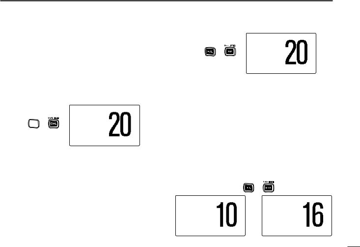
■ Channel selection
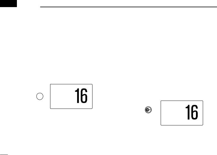
ï Channel 16
Channel 16 is the distress and safety channel. It is used for establishing initial contact with a station and for emergency communications. Channel 16 is monitored during both Dualwatch and Tri-watch. While standing by, you must monitor Channel 16.
Push [16•C] momentarily to select Channel 16.
Push [DIAL•DUAL/GRP] to return to the condition before selecting Channel 16, or rotate [CHANNEL] to select an operating channel.
25W INT
TAG
Push 
34°34.506N
123°23.236W
UTC 12:00 CALLING
ï Call channel
Each regular channel group has a separate leisure-use call channel. The call channel is monitored during Tri-watch. The call channels can be programmed (p. 9) and are used to store your most often used channel in each channel group for quick recall.
Push [16•C] for 1 sec. to select the call channel of the selected channel group.
•“CALL” and call channel number appear.
•Each channel group may have an independent call channel after programming a call channel. (p. 9)
Push [DIAL•DUAL/GRP] to return to the condition before selecting call channel, or rotate [CHANNEL] to select an operating channel.
|
25W |
INT CALL |
Push |
TAG |
|
|
|
|
for 1 sec. |
34°34.506N |
|
|
|
|
|
123°23.236W |
|
|
UTC 12:00 |
CALLING |
6
ï International channels
There are pre-programmed 57 international channels for the IC-M505.
q Push [DIAL•DUAL/GRP] to select a regular channel.
wWhile pushing and holding [H/L], push [DIAL•DUAL/GRP] to change the channel group, if necessary.
• “INT” appears when International channel is selected.
eRotate [CHANNEL] to select a channel.
• “DUP” appears for duplex channels.
25W INT DUP
TAG
Push  +
+
34°34.506N
123°23.236W
UTC 12:00 PORT OPR
ï U.S.A. channels (U.K. version only)
For U.K. version, there are pre-programmed 58 U.S.A. channels in addition to 57 International channels.
q Push [DIAL•DUAL/GRP] to select a regular channel.
wWhile pushing and holding [H/L], push [DIAL•DUAL/GRP] to change the channel group, if necessary.
•International and U.S.A. channels can be selected in sequence. e Rotate [CHANNEL] to select a channel.
•“DUP” appears for duplex channels.
BASIC OPERATION 3
|
25W USA |
|
DUP |
|
TAG |
Push |
+ |
34°34.506N |
3 |
123°23.236W |
|
|
|
UTC 12:00 PORT OPR |
|
ï ATIS and DSC channels
(Holland and FRG versions only)
For Holland and FRG version, there are pre-programmed 57 ATIS and 57 DSC* channels in addition to 57 International channels.
*FRG version only
q Push [DIAL•DUAL/GRP] to select a regular channel.
wWhile pushing and holding [H/L], push [DIAL•DUAL/GRP] to change the channel group, if necessary.
•International, ATIS and DSC channels can be selected in sequence. e Rotate [CHANNEL] to select a channel.
•“DUP” appears for duplex channels.
Push |
+ |
|
1W ATIS |
25W |
DSC |
TAG |
TAG |
|
|
34°34.506N |
|
|
123°23.236W |
|
COMMERCIAL |
UTC 12:00 |
CALLING |
ATIS channel |
DSC channel |
|
7
3 BASIC OPERATION
■ Receiving and transmitting
 CAUTION: Transmitting without an antenna may dam-
  age the transceiver.
q Push [POWER] to turn power ON.
wSet the audio and squelch levels.
Rotate [SQL] fully counterclockwise in advance.
Rotate [VOL] to adjust the audio output level.
Rotate [SQL] clockwise until the noise disappears.
e While pushing and holding [H/L], push [DIAL•DUAL/GRP] to change the channel group. (p. 7)
r Rotate [CHANNEL] to select the desired channel. (pgs. 6, 7)
• When receiving a signal, “BUSY” appears and audio is emitted from the speaker.
• Further adjustment of [VOL] may be necessary.
t Push [H/L] to select the output power if necessary.
• “25W” or “1W” appears when high or low power is selected, respectively.
• Choose low power for short range communications, choose high power for longer distance communications.
• Some channels are for low power only.
y Push and hold [PTT] to transmit, then speak into the microphone.
•“TX” appears.
•Channel 70 cannot be used for transmission other than DSC. u Release [PTT] to receive.
 IMPORTANT: To maximize the readability of your trans-
mitted signal, pause a few sec. after pushing [PTT], hold
 the microphone 5 to 10 cm from your mouth and speak
  into the microphone at a normal voice level.
q y |
|
ui Microphone |
|||||||||||
|
|
|
|
|
|
|
|
|
|
|
|
|
|
|
|
|
|
|
|
|
|
|
|
|
|
|
|
|
|
|
|
|
|
|
|
|
|
|
|
|
|
|
|
|
|
|
|
|
|
|
|
|
|
|
|
|
|
|
|
|
|
|
|
|
|
|
|
|
|
|
|
|
|
|
|
|
|
|
|
|
|
|
|
|
|
|
|
|
|
|
|
|
|
|
|
|
|
|
|
|
|
|
|
|
|
|
|
|
|
|
|
|
|
|
|
|
|
|
|
|
|
|
|
|
|
|
|
|
|
|
|
|
|
|
|
|
|
|
|
|
|
|
|
|
|
|
|
|
|
|
|
|
|
|
|
|
|
|
|
|
|
|
|
|
|
|
|
|
|
|
|
|
|
|
|
|
|
|
|
|
|
|
|
|
|
|
|
|
|
|
|
|
|
|
|
|
|
|
|
|
|
|
|
|
|
|
|
|
|
w w e r |
t r |
e y |
8
■ Call channel programming
You can program the call channel with your most often-used channels in each channel group for quick recall.
qWhile pushing and holding
[H/L], push [DIAL•DUAL• GRP] one or more times to select the desired channel group (INT, USA, ATIS or DSC) to be programmed.
wPush [16•C] for 1 sec. to select the call channel of the selected channel group.
•“CALL” and call channel number appear.
ePush [16•C] again for 3 sec. (until a long beep changes to 2 short beeps) to enter call channel programming.
•Channel number starts blinking.
25W INT DUP
TAG
34°34.506N
123°23.236W
UTC 12:00 INTL
25W INT CALL
TAG
34°34.506N
123°23.236W
UTC 12:00 CALLING
25W INT CALL
TAG
34°34.506N
123°23.236W
UTC 12:00 CALLING
BASIC OPERATION 3
rRotate [CHANNEL] to select the desired channel.
tPush [16•C] to program the displayed channel as the call channel.
•Push [CLR] to cancel.
•The channel number stops blinking.
25W INT |
CALL |
DUP |
3 |
TAG |
34°34.506N
123°23.236W
UTC 12:00 INTL
25W INT CALL DUP
TAG
34°34.506N
123°23.236W
UTC 12:00 INTL
9

3 BASIC OPERATION
■ Channel comments
Memory channels can be labelled with a unique alphanumeric ID of up to 10 characters.
Capital letters, small letters, 0 to 9, some symbols (/ . –) and space can be used.
qSelect the desired channel.
• Cancel Dualwatch, Tri-watch or Scan in advance.
w While pushing and holding [H/L], push [16•C] to edit the
channel comment. |
25W INT |
|||
• A cursor and the first char- |
||||
|
|
|
||
acter start blinking alter- |
TAG |
|||
|
|
|
||
nately. |
|
|
|
|
e Select the desired charac- |
34°34.506N |
|||
123°23.236W |
||||
ter by rotating [CHAN- |
||||
|
||||
UTC 12:00 |
P |
LEASURE__ |
||
|
||||
NEL]. |
|
|
|
|
•Push [16•C] or [DIAL•DUAL/GRP] to move the cursor forward or backward, respectively.
r Repeat step e to input all characters.
tPush [CHANNEL•ENTER] to input and set the comment.
•Push [CLR] to cancel.
•The cursor and the character stop blinking.
yRepeat steps q to t to program other channel comments, if desired.
■ Microphone Lock function
The Microphone Lock function electrically locks [Y]/[Z] and [HI/LO] keys on the supplied microphone. This prevents accidental channel changes and function access.
While pushing and holding [HI/LO] on the microphone, turn power ON to toggle the Lock function ON and OFF.
[Y]/[Z] |
[HI/LO] |
■ Display backlight
The function display and keys can be backlit for better visibility under low light conditions.
While pushing and holding [H/L], rotate [CHANNEL] to adjust the brightness of the LCD and key backlight.
•The backlight is adjustable in 7 levels and OFF.
10
BASIC OPERATION 3
■ Optional voice scrambler operation
D Activating the scrambler |
|
|
D Programming scrambler codes |
|
|
|||||
The optional voice scrambler provides private communica- |
There are 32 codes (1 to 32) or 128 codes (0 to 127)* avail- |
3 |
||||||||
tions. In order to receive or send scrambled transmissions |
able for programming when an optional scrambler unit is in- |
|
|
|||||||
you must first activate the scrambler function. To activate the |
stalled. In order to understand one another, all transceivers |
|
|
|||||||
function, an optional scrambler unit is necessary. See pgs. |
in your group must have the same scramble code. This func- |
|
|
|||||||
57, 62 for setting the scrambler unit. Ask your dealer for de- |
tion may not be available depending on dealer setting. |
|
|
|||||||
tails. |
|
|
|
|
*Depends on the installed scrambler unit. |
|
|
|||
The scrambler function automatically turns OFF when |
q Turn power OFF. |
|
|
|
|
|||||
Channel 16 or 70 is selected. |
|
|
w While pushing [16•C], turn power ON to enter set mode. |
|
|
|||||
|
|
|
|
|
e After the display appears, release [16•C]. |
|
|
|||
q Rotate [CHANNEL] to select an operating channel other |
r Rotate [CHANNEL] to select the “Scrambler Code,” |
|
|
|||||||
than Channel 16 and 70. |
|
|
push [CHANNEL•ENTER]. |
|
|
|
|
|||
w While pushing and holding [H/L], push [IC] to turn the op- |
t Rotate [CHANNEL] to select the desired scrambler code. |
|
|
|||||||
tional scrambler function ON. |
|
|
y Push [CHANNEL•ENTER] to set and exit the scrambler |
|
|
|||||
• “SCRAM” appears. |
|
|
code item. |
|
|
|
|
|
||
e To turn the scrambler function OFF, repeat step w. |
|
u Push [CLR], or rotate [CHANNEL] to select “Exit,” push |
|
|
||||||
• “SCRAM” disappears. |
|
|
[CHANNEL•ENTER] to exit set mode. |
|
|
|||||
|
|
|
|
|
|
|
|
|||
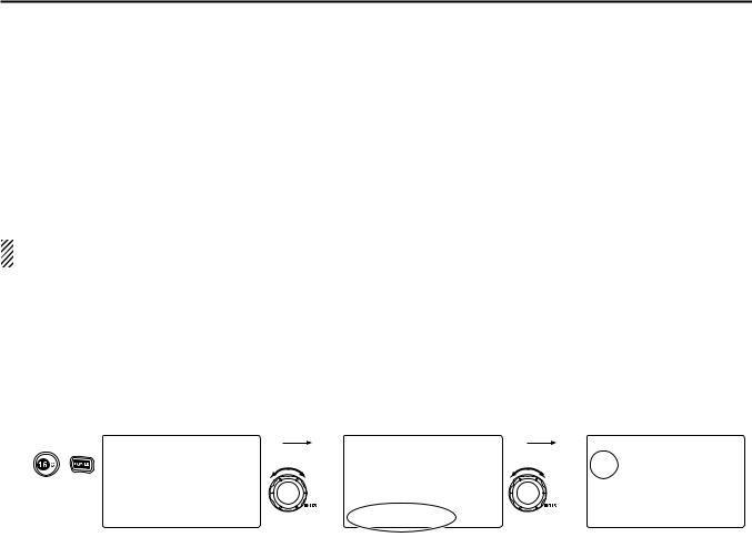
[Example]: Programming scrambler code 5. |
|
|
|
|
|
|
|
|||
|
|
--Set Mode-- |
Rotate |
|
--Set Mode-- |
Rotate |
--Set Mode-- |
|
|
|
Push |
+ |
˘Scan Type |
|
Dual/Tri |
Scrambler Code |
|
|
|
||
Scan Timer |
|
|
Beep |
|
˘5 Select |
|
|
|
||
to enter set mode. |
Dual/Tri |
|
|
Contrast |
|
4 |
|
|
|
|
Beep |
|
|
Foghorn Frequency |
|
3 |
|
|
|
||
|
|
Contrast |
|
|
Radio Power |
|
2 |
|
|
|
|
|
Foghorn Frequency |
|
|
Scrambler Type |
|
1 |
|
|
|
|
|
Radio Power |
to select item, |
˘Scrambler Code |
to select code, |
<ENT˘OK> |
|
|
|
|
|
|
|
|
|
|
|
|
|
||
|
|
|
then push. |
|
Select |
then push. |
|
|
|
|
|
|
|
|
|
|
|
|
|
|
|
|
|
|
|
|
|
|
|
|
|
|
11
 4 SCAN OPERATION
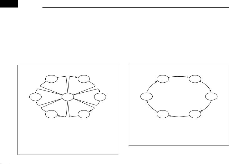
■ Scan types
Scanning is an efficient way to locate signals quickly over a wide frequency range. The transceiver has Priority scan and Normal scan.
PRIORITY SCAN
|
CH 01 |
CH 02 |
CH 06 |
CH 16 |
CH 03 |
|
CH 05 |
CH 04 |
Priority scan searches through all TAG channels in sequence while monitoring Channel 16. When a signal is detected on Channel 16, scan pauses until the signal disappears; when a signal is detected on a channel other than Channel 16, scan becomes Dualwatch until the signal disappears.
Set the TAG channels (scanned channel) before scanning. Clear the TAG channels which inconveniently stop scanning, such as those for digital communication use. (Refer to right page for details.)
 Choose Priority or Normal scan in Set mode. (p. 55)
NORMAL SCAN
CH 01 |
CH 02 |
CH 06 |
CH 03 |
CH 05 |
CH 04 |
Normal scan, like Priority scan, searches through all TAG channels in sequence. However, unlike Priority scan, Channel 16 is not checked unless Channel 16 is set as a TAG channel.
12
■ Setting TAG channels
For more efficient scanning, add the desired channels as TAG channels or clear the TAG for unwanted channels. Channels that are not tagged will be skipped during scanning. TAG channels can be assigned to each channel group (INT, USA, ATIS or DSC) independently.
qWhile pushing and holding [H/L], push [DIAL•DUAL/GRP] to select the desired channel group (INT, USA, ATIS or DSC.)
w Select the desired channel to be set as a TAG channel.
ePush [SCAN•TAG] for 1 sec. to set the displayed channel as a TAG channel.
• “TAG” appears in the display.
rTo cancel the TAG channel setting, repeat step e.
• “TAG” disappears.
Clearing (or setting) all tagged channels
While pushing and holding [H/L], push [SCAN•TAG] for 3 sec. (until a long beep changes to 2 short beeps) to clear all TAG channels setting in the channel group.
• Repeat above procedure to set all TAG channels.
SCAN OPERATION 4
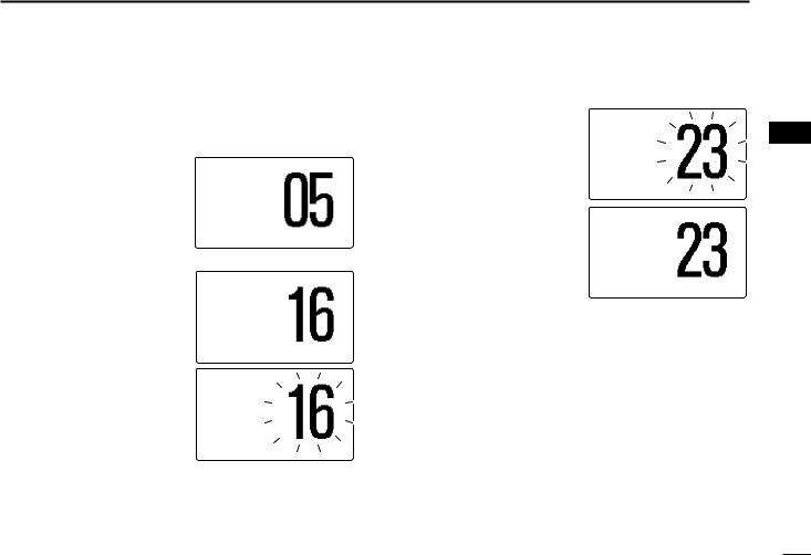
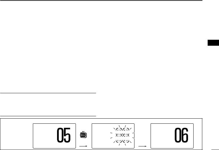
■ Starting a scan
Set scan type (Priority or Normal scan) and scan resume timer in advance, using Set mode. (p. 55)
q While pushing and holding [H/L], push [DIAL•DUAL/GRP] |
4 |
to select the desired channel group (INT, USA, ATIS or DSC) if desired.
w Set TAG channels as described at left.
e Make sure the squelch is closed to start a scan.
rPush [SCAN•TAG] to start Priority or Normal scan.
•“PRI-SCAN 16” appears at the channel comment indicator during Priority scan.
•“NORMAL SCAN” appears at the channel comment indicator during Normal scan.
•When a signal is detected, scan pauses until the signal disappears or resumes after pausing 5 sec. according to Set mode setting. (Channel 16 is still monitored during Priority scan.)
•Rotate [CHANNEL] to check the scanning TAG channels, to change the scanning direction or resume the scan manually.
•A beep tone sounds and “16” blinks at the channel comment indicator when a signal is received on Channel 16 during Priority scan.
[Example]: Starting a normal scan. |
|
Scan starts. |
|
|
|
When a signal is received |
||||||||||||||
25W |
INT |
Push |
25W |
INT |
|
|
|
BUSY 25W |
INT |
|||||||||||
DUP |
|
DUP |
|
|
|
|
|
|
|
|
|
|
|
|
||||||
|
|
|
|
|
|
|
|
|
|
|
|
|
|
|||||||
TAG |
|
|
TAG |
|
|
|
|
|
|
|
|
|
|
|
|
|
TAG |
|
||
|
|
|
NORMAL SCAN |
|
|
|
|
|
|
|
|
|
|
|
|
|
|
NORMAL SCAN |
|
|
34°34.506N |
|
|
34°34.506N |
|
|
|
|
|
|
|
|
|
|
|
|
|
34°34.506N |
|
||
|
|
|
|
|
|
|
|
|
||||||||||||
123°23.236W |
|
|
123°23.236W |
|
|
|
|
|
|
|
|
|
|
123°23.236W |
|
|||||
|
|
|
|
|
|
|||||||||||||||
UTC 12:00 |
INTL |
|
UTC 12:00 |
|
|
|
UTC 12:00 |
SAFETY |
||||||||||||
13

 5 DUALWATCH/TRI-WATCH
■ Description
Dualwatch monitors Channel 16 while you are receiving on another channel; Tri-watch monitors Channel 16 and the call channel while receiving another channel. Dualwatch/Triwatch is convenient for monitoring Channel 16 when you are operating on another channel.
DUALWATCH/TRI-WATCH SIMULATION
Call channel
Dualwatch |
Tri-watch |
•If a signal is received on Channel 16, Dualwatch/Tri-watch pauses on Channel 16 until the signal disappears.
•If a signal is received on the call channel during Tri-watch, Tri-watch becomes Dualwatch until the signal disappears.
•To transmit on the selected channel during Dualwatch/Triwatch, push and hold [PTT].
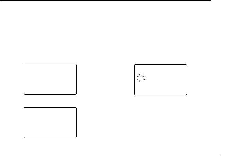
■ Operation
q Select Dualwatch or Tri-watch in Set mode. (p. 56)
w Rotate [CHANNEL] to select the desired operating channel.
ePush [DIAL•DUAL/GRP] for 1 sec. to start Dualwatch or Tri-watch.
•“DUAL 16” appears during Dualwatch; “TRI 16” appears during Tri-watch.
•A beep tone sounds when a signal is received on Channel 16. r To cancel Dualwatch/Tri-watch, push [DIAL•DUAL/GRP]
again.
[Example]: Operating Tri-watch on INT Channel 25
Tri-watch starts. |
|
Signal is received on call |
||
|
|
channel. |
|
|
25W INT |
|
BUSY 25W |
INT |
CALL |
DUP |
|
|
DUP |
|
TAG |
|
TAG |
|
|
TRI 16 |
|
TRI |
16 |
|
34°34.506N |
|
34°34.506N |
|
|
123°23.236W |
|
123°23.236W |
|
|
UTC 12:00 TELEPHONE |
|
UTC 12:00 |
INTL |
|
Tri-watch resumes after the |
|
Signal received on Channel |
|
signal disappears. |
|
16 takes priority. |
|
25W INT |
|
BUSY 25W |
INT |
DUP |
|
|
DUP |
TAG |
|
TAG |
|
TRI 16 |
|
TRI |
16 |
34°34.506N |
|
34°34.506N |
|
123°23.236W |
|
123°23.236W |
|
UTC 12:00 TELEPHONE |
|
UTC 12:00 TELEPHONE |
|
14
■ MMSI code programming
The 9-digit MMSI (Maritime Mobile Service Identity: DSC self ID) code can be programmed at power ON.
 This code programming can be performed only once.
q Turn power OFF.
w While pushing [MENU], turn power ON to enter MMSI code programming condition.
e After the display appears, release [MENU]. r Push [MENU] again to enter the DSC menu.
tRotate [CHANNEL] to select “Set up,” push [CHANNEL•ENTER].
--DSC Menu-- Select Item
Position Input Received Calls
˘Set up Exit
yRotate [CHANNEL] to select “MMSI Check,” push
[CHANNEL•ENTER].
--DSC Menu--
Set up
Add:INDV ID
Add:Group ID
DEL:INDV ID
DEL:Group ID
Offset Time
˘MMSI Check
DSC OPERATION 6 
uRotate [CHANNEL] to set the specific 9-digit MMSI code.
•Push [16•C] or [DIAL•DUAL/GRP] to move the cursor forward or backward, respectively.
•Push [CLR] to cancel and return to the set up menu.
|
|
--DSC Menu-- |
5 |
|
MMSI Check |
|
|||
|
||||
6 |
||||
|
||||
|
_ |
________ |
||
|
|
|
||
<CLR˘Exit / ENT˘OK>
iAfter entering the 9-digit code, push [CHANNEL•ENTER] to set the code.
• Returns to the set up menu.
oPush [CLR] or rotate [CHANNEL] to select “Exit,” push
[CHANNEL•ENTER].
•Returns to the DSC menu.
•Repeat again to return to the normal operation condition.
15

6 DSC OPERATION
■ MMSI code check
The 9-digit MMSI (DSC self ID) code can be checked.
q Push [MENU] to enter the DSC menu.
wRotate [CHANNEL] to select “Set up,” push [CHANNEL•ENTER].
--DSC Menu-- Select Item
Position Report Polling Request Received Calls Distress Setting
˘Set up Exit
eRotate [CHANNEL] to select “MMSI Check,” push
[CHANNEL•ENTER].
--DSC Menu-- Set up
DEL:Group ID
Offset Time ˘MMSI Check
Auto ACK NMEA Output Exit
r Check the 9-digit MMSI (DSC self ID) code.
--DSC Menu--
MMSI Check
123456789
<CLR˘Exit>
tPush [CLR] or rotate [CHANNEL] to select “Exit,” push
[CHANNEL•ENTER].
•Returns to the DSC menu.
•Repeat again to return to the normal operation condition.
16
■ DSC address ID
A total of 100 DSC address IDs can be programmed and named with up to 10 characters.
D Programming Individual ID q Push [MENU] to enter the DSC menu.
wRotate [CHANNEL] to select “Set up,” push [CHANNEL•ENTER].
--DSC Menu-- Select Item
Position Report Polling Request Received Calls Distress Setting
˘Set up Exit
eRotate [CHANNEL] to select “Add:INDV ID,” push
[CHANNEL•ENTER].
--DSC Menu-- Set up
˘Add:INDV ID Add:Group ID DEL:INDV ID DEL:Group ID Offset Time MMSI Check
DSC OPERATION 6
rRotate [CHANNEL] to set the individual ID and ID name.
•Push [16•C] or [DIAL•DUAL/GRP] to move the cursor forward or backward, respectively.
•Push [CLR] to cancel and return to the set up menu.
•“Full ID” appears when 100 DSC address IDs are already set.
• After inputting the 9-digit MMSI number, push [CHANNEL• |
6 |
||||
ENTER] or [16•C] to enter a 10-character ID name. |
|||||
|
|||||
|
|
--DSC |
Menu-- |
|
|
Add:Individual ID |
|
||||
Input 9 digits |
|
||||
|
|
|
|||
|
|
_________ |
|
|
|
Input name |
|
|
|||
_________ |
|
|
|||
<CLR˘Exit |
/ ENT˘OK> |
|
|||
t After inputting, push [CHANNEL•ENTER] to program.
yPush [CLR] or rotate [CHANNEL] to select “Exit,” push
[CHANNEL•ENTER].
•Returns to the DSC menu.
•Repeat again to return to the normal operation condition.
17

6 DSC OPERATION
D Deleting Individual ID
q Push [MENU] to enter the DSC menu.
wRotate [CHANNEL] to select “Set up,” push [CHANNEL•ENTER].
--DSC Menu-- Select Item
Position Report Polling Request Received Calls Distress Setting
˘Set up Exit
eRotate [CHANNEL] to select “DEL:INDV ID,” push
[CHANNEL•ENTER].
•When no address ID is programmed, “No ID” is displayed. Push [CLR] to exit.
--DSC Menu-- Set up
Add:INDV ID
Add:Group ID ˘DEL:INDV ID
DEL:Group ID
Offset Time
MMSI Check
rRotate [CHANNEL] to select the desired ID name for deleting.
--DSC Menu-- Select ID
John
Paul ˘George
Michael
<CLR˘Exit / ENT˘OK>
tPush [CHANNEL•ENTER] to delete the address ID and return to the set up menu.
yPush [CLR] or rotate [CHANNEL] to select “Exit,” push
[CHANNEL•ENTER].
•Returns to the DSC menu.
•Repeat again to return to the normal operation condition.
18
 Loading...