


INSTRUCTION MANUAL
VHF FM REPEATER
iFR3000
UHF FM REPEATER
iFR4000

IMPORTANT
READ THIS INSTRUCTION MANUAL CAREFULLY before attempting to operate the repeater.
SAVE THIS INSTRUCTION MANUAL– This manual contains important safety and operating instructions for the IC-FR3000/FR4000 series.
EXPLICIT DEFINITIONS
WORD |
DEFINITION |
RWARNING |
Personal injury, fire hazard or electric |
|
shock may occur. |
CAUTION |
Equipment damage may occur. |
|
|
NOTE |
If disregarded, inconvenience only. |
No risk of personal injury, fire or |
|
|
electric shock. |
PRECAUTION
RWARNING HIGH VOLTAGE! NEVER attach an antenna or internal antenna connector during transmission. This may result in an electrical shock or burn.
RWARNING HIGH VOLTAGE! NEVER install the antenna at any place that person touch the antenna easily during transmission. This may result in an electrical shock or burn.
RNEVER apply AC to the [BATTERY] terminals on the repeater rear panel. This could cause a fire or damage the repeater.
RNEVER apply more than 16 V DC, such as a 24 V battery, to the [BATTERY] terminals on the repeater rear panel. This could cause a fire or damage the repeater.
RNEVER let metal, wire or other objects touch any internal part or connectors on the rear panel of the repeater. This may result in an electric shock.
RNEVER expose the repeater to rain, snow or any liquids.
AVOID using or placing the repeater in areas with temperatures below –30°C (–22°F) or above +60°C (+140°F). Be aware that temperatures on a vehicle’s dashboard can exceed 80°C (+176°F), resulting in permanent damage to the repeater if left there for extended periods.
AVOID placing the repeater in excessively dusty environments or in direct sunlight.
AVOID putting anything on top of the repeater. This will obstruct heat dissipation.
Place the repeater in a secure place to avoid inadvertent use by children.
BE CAREFUL! The heatsink will become hot when operating the repeater continuously for long periods.
BE CAREFUL! If a linear amplifier is connected, set the repeater’s RF output power to less than the linear amplifier’s maximum input level, otherwise, the linear amplifier will be damaged.
Use Icom microphones only (optional). Other manufacturer’s microphones have different pin assignments, and connection to the IC-FR3000/FR4000 series may damage the repeater.
For U.S.A. only
CAUTION: Changes or modifications to this repeater, not expressly approved by Icom Inc., could void your authority to operate this repeater under FCC regulations.
CAUTION: This repeater is intended for use as a fixed base station with the antenna located outdoors on the rooftop or on antenna tower.
Icom, Icom Inc. and the 
 logo are registered trademarks of Icom Incorporated (Japan) in the United states, the United Kingdom, Germany, France, Spain, Russia and/or other countries.
i

DECLARATION OF CONFORMITY
For U.S.A.
This equipment complies with the Federal Communications Commission (FCC) rules and regulations governing telephone equipment and the Technical Requirements for Connection to the Telephone Network published by the industry’s Administrative Council for Terminal Attachments (ACTA). On the right side of this equipment is a label that contains, among other information, a product identifier in the format US:ICMOT03BIC-FR4000. If requested, this number must be provided to the telephone company.
The applicable certification jack (connector) USOC-RJ- 11C is used for this equipment.
This device can only be connected to the Public Switched Telephone Network (PSTN) using a telephone cord and modular plug that is compliant with the criteria adopted by the ACTA. This equipment is designed for connection to the telephone network or premises wiring using a compatible modular jack that is also compliant.
The Ringer Equivalence Number (or REN) is used to determine the number of devices that may be connected to a telephone line. Excessive RENs on a telephone line may result in the devices not ringing in response to an incoming call. In most, but not all areas, the sum of RENs should not exceed five (5.0). To be certain of the number of devices that may be connected to a line, as determined by the total RENs, contact the local telephone company. The REN for this product is printed on the product identifier label
CAUTION: If this equipment is deemed potentially harmful to the telephone network, the telephone company will attempt to notify you in advance of discontinuing service. If advance notice is not practical, the telephone company will notify you as soon as possible. If service is disconnected, you will be advised of your right to file a complaint with the Federal Communications Commission (FCC) should you believe it necessary.
The telephone company may make changes in its facilities, equipment, operations or procedures that could affect the operation of this equipment. Should this occur, advance notice you be provided in order for you to make necessary modifications to maintain uninterrupted service.
Should you experience trouble with this equipment, please contact: ICOM America, Technical Support at 425-454-7619 for repair or warranty information. If the equipment is causing harm to the telephone network, the telephone company may request that you disconnect the equipment until the problem is resolved.
There are no user serviceable parts for a telephone circuit inside of this IC-FR3000 or IC-FR4000.
NOTICE: Connection to party line service is subject to state tariffs. Contact the state public utility commission, public service commission or corporation commission for information.
If your home has specially wired alarm equipment connected to the telephone line, ensure the installation of this IC-FR3000 or IC-FR4000 does not disable your alarm equipment. If you have questions about what will disable alarm equipment, consult your telephone company or a qualified installer.
For CANADA
NOTICE: This equipment meets the applicable Industry Canada Terminal Equipment Technical Specifications. This is confirmed by the registration number. The abbreviation, IC, before the registration number signifies that registration was performed based on a Declaration of Conformity indicating that Industry Canada technical specifications were met. It does not imply that Industry Canada approved the equipment.
NOTICE: The Ringer Equivalence Number (REN) for this terminal equipment is 0.3. The REN assigned to each terminal equipment provides an indication of the maximum number of terminals allowed to be connected to a telephone interface. The termination on an interface may consist of any combination of devices subject only to the requirement that the sum of the Ringer Equivalence Numbers of all the devices does not exceed five.
ii
FORWARD
Thank you for purchasing this Icom product. The ICFR3000/FR4000 VHF/UHF FM REPEATER is designed and built with Icom’s state of the art technology and craftsmanship. With proper care, this product should provide you years of trouble-free operation.
We want to take a couple of moments of your time to thank you for making the IC-FR3000/FR4000 your repeater of choice, and hope you agree with Icom’s philosophy of “technology first.” Many hours of research and development went into the design of your ICFR3000/FR4000 series.
D FEATURES
50 W continuous full duty cycle operation
This repeater looks as good as it performs. A rugged heatsink, large cooling fans and a high performance power module provide the repeater with a stable
50W at full duty cycle operation.
Automatic battery backup system
A built-in backup system supports automatic switching to an external power supply (13.6 V DC) if the AC power supply fails.
Multiple CTCSS & DTCS tone memories with multiple memory channels
Up to 16 CTCSS/DTCS tones (TX/RX tones respectively) can be programmed in a channel. This feature allows you to share a channel with multiple user groups. You can also give priority/exclusive use to a specified group simply by programming different tones to another memory channel. Ideal for many different applications.
Built-in 2-Tone, 5-Tone, DTMF encoder & decoder
Multiple signaling systems are equipped as standard. These systems are fully compatible with Icom F-series radios.
Telephone interconnect capability
DTMF remote control capability
You can control the repeater from a remote location over the air or over a phone line with DTMF.
Other features
-PC programmable
-Wall or 19 inch rack mount (optional MB-77/MB-78)
-Optional Voice Scrambler Unit (UT-109 #01/UT-110 #01) for base operating mode
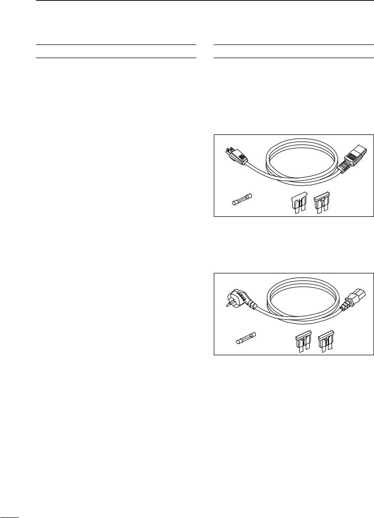
SUPPLIED ACCESSORIES
The following accessories are supplied with ICFR3000/FR4000 series
[AC120V version]
q AC power cable (OPC-510) ……………………… 1 w Spare fuses (FGB 1 A) …………………………… 1 e Spare fuses (ATC 20)……………………………… 2
q
we 
[AC220V version]
q AC power cable (OPC-492) ……………………… 1 w Spare fuses (FGB 1 A) …………………………… 1 e Spare fuses (ATC 20)……………………………… 2
q
w |
e |
iii

TABLE OF CONTENTS
IMPORTANT ............................................................ |
i |
|
EXPLICIT DEFINITIONS ......................................... |
i |
|
PRECAUTION ......................................................... |
i |
|
DECLARATION OF CONFORMITY ....................... |
ii |
|
FORWARD ............................................................. |
iii |
|
SUPPLIED ACCESSORIES .................................. |
iii |
|
TABLE OF CONTENTS ......................................... |
iv |
|
1 |
PANEL DESCRIPTION ......................... |
1 – 4 |
|
■ Front panel .................................................... |
1 |
|
■ Rear panel ..................................................... |
2 |
|
D Remote connector...................................... |
3 |
|
D Accessory connector.................................. |
3 |
2 |
INSTALLATION AND |
|
|
CONNECTIONS .................................. |
5 – 10 |
|
■ Unpacking ..................................................... |
5 |
|
■ Selecting a location ....................................... |
5 |
|
■ Antenna connection ....................................... |
5 |
|
■ Duplexer ........................................................ |
5 |
|
■ Grounding ...................................................... |
5 |
|
■ Required connections .................................... |
6 |
|
■ Advanced connections .................................. |
7 |
|
■ Power ............................................................ |
8 |
|
D In AC operation .......................................... |
8 |
|
D In DC operation.......................................... |
8 |
|
■ Mounting the repeater ................................... |
8 |
|
D Using the optional MB-78........................... |
8 |
|
D Using the optional MB-77......................... |
10 |
3 |
OPTIONAL UNIT INSTALLATION |
........... 11 |
|
■ Opening the repeater’s case ....................... |
11 |
|
■ Voice scrambler unit installation .................. |
11 |
4 |
OPERATION ............................................ |
12 |
|
■ Turning power ON ....................................... |
12 |
|
■ Receiving and transmitting .......................... |
12 |
|
D Receiving ................................................. |
12 |
|
D Transmitting ............................................. |
12 |
5 |
MAINTENANCE ................................ |
13 –14 |
|
■ Troubleshooting ........................................... |
13 |
|
■ Fuse replacement ........................................ |
14 |
6 |
SPECIFICATIONS AND OPTIONS ... |
15 –16 |
|
■ Specifications .............................................. |
15 |
|
D IC-FR3000 ............................................... |
15 |
|
D IC-FR4000 ............................................... |
15 |
|
■ Options ........................................................ |
16 |
iv
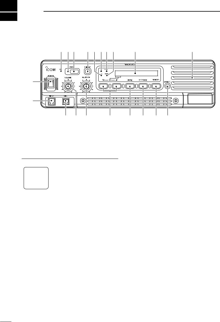
1 PANEL DESCRIPTION
■ Front panel
!9 !8!7 !6 !5 !4!3!2 |
Function display (p. 2) |
!1 |
q
w
e r t
y u i o !0
q POWER SWITCH [POWER]
Toggles to turn the repeater power ON or OFF.
w MICROPHONE/SPEAKER CONNECTOR [MIC/SP]
This 8-pin modular jack accepts the optional microphone.
|
|
|
|
|
|
|
|
|
|
|
q+9 V DC output (Max. 10 mA) |
|
|
|
|
|
|
|
|
|
|
|
wI/O port for PC programming |
|
|
|
|
|
|
|
|
|
|
|
eNC |
|
|
|
|
|
|
|
|
|
|
|
|
|
|
|
|
|
|
|
|
|
|
|
rM PTT (Input port for TX control) |
|
q |
i |
|||||||||
|
|
|
|
|
|
|
|
|
|
|
tMicrophone ground |
|
|
|
|
|
|
|
|
|
|
|
yMicrophone input |
|
|
|
|
|
|
|
|
|
|
|
uGround |
|
|
|
|
|
|
|
|
|
|
|
|
|
|
|
|
|
|
|
|
|
|
|
|
|
|
|
|
|
|
|
|
|
|
|
iM MONI (Input port for monitor control) |
|
|
|
|
|
|
|
|
|
|
|
|
e LINE CONNECTOR [LINE]
This 4-pin modular jack accepts to connect to 2 wire system telephone cable.
•See p. 7 for line connector information.
r VOLUME CONTROL [VOLUME] (p. 12) Adjusts the audio output level.
t SQUELCH CONTROL [SQUELCH]
While in base operating mode, adjusts the squelch threshold level. (p. 12)
While in repeater operating mode, this knob is not activate.
y CHANNEL SELECT SWITCHES [DN/UP]
Push either switch to select the operating channel.
u MONITOR SWITCH [MONI]
Push to monitor the operating frequency.
i MODE SELECT SWITCH [RPT/BASE]
Toggles the repeater or base operating mode when pushed.
•When setting up a repeater system using ICFR3000/FR4000 only, select a repeater operating mode.
•When using IC-FR3000/FR4000 as full (or half) duplex transceiver or setting up a repeater system connecting an external controller, select a base operating mode.
o REMOTE CONTROL SWITCH [REMOTE]
Toggles to activate or inactivate the remote control operation when pushed.
!0AF MUTE CONTROL [SP MUTE]
Mutes the audio output.
!1INTERNAL SPEAKER
Monitors received signals.
!2BASE OPERATING MODE INDICATOR
Lights green while in base operating mode.
!3REMOTE CONTROL MODE INDICATOR
Lights green while in remote control operation.
!4TRANSMIT INDICATOR
Lights red while transmitting.
!5BUSY INDICATOR
Lights green while receiving a signal or when the noise squelch is open.
1

!6ANI CLEAR SWITCH [ANI CLR]
Push for 1 sec. to clear the received ANI ID indication on the display and returns to original indication.
 NOTE: This switch is no function available for some
  versions.
!7DEALER-PROGRAMMABLE SWITCH [PROG]
Toggles the pre-programmed function ON or OFF when pushed.
!8PROGRAMMED FUNCTION INDICATOR
Lights green while pre-programmed function is activated.
!9DC INDICATOR
Lights green when in DC operation.
PANEL DESCRIPTION |
1 |
DFunction display
32HH@HICOMHINC.
q w e |
r |
q MEMORY CHANNEL INDICATOR
Shows the selected memory channel.
w TRANSMIT POWER INDICATOR
Shows the output power level.
e AUDIBLE INDICATOR
“@” appears in an audible condition, disappears in an inaudible condition. (When an audible condition, audio mute is cancelled.)
r ALPHANUMERIC INDICATORS
Shows the variety text or code information.
■ Rear panel
EXT SP |
REMOTE |
|
RX |
TX/TX•RX |
|
ACC |
|
|
|
BATTERY
AC
GND
i
q w |
e |
r |
qTRANSMIT ANTENNA CONNECTOR [TX/TX•RX]
Connects a transmit antenna (impedance: 50 Ω) and outputs transmit signals.
When installing an optional internal duplexer (supplied by third party), this connects the transmit receive to an antenna.
w EXTERNAL SPEAKER CONNECTOR [EXT SP]
Accepts a 4 Ω external speaker.
e REMOTE CONNECTOR [REMOTE]
Connects to the remote controller.
• See p. 3 for remote connector information.
r ACCESSORY CONNECTOR [ACC]
Connects to the remote controller.
• See pgs. 3, 4 for accessory connector information.
t RECEIVE ANTENNA CONNECTOR [RX]
Connects a receive antenna (impedance: 50 Ω) and inputs receiving signals.
t y |
u |
When installing an internal duplexer (supplied by third party), do not use this connector.
y AC POWER SOCKET [AC]
Connects the supplied AC power cable to a domestic AC outlet.
u GROUND TERMINAL [GND]
Ground the repeater through this terminal to prevent electric shocks, TVI, BCI and other problems.
i DC POWER INPUT TERMINALS [BATTERY]
Connects the 12 V storage battery for the repeater backup when the AC power is interrupted. These terminals are also used for DC power operation.
 CAUTION: NEVER short the (+) line of the DC
power cable to repeater’s chassis, when connecting
 DC power cable to the [BATTERY] terminals. Oth-
  erwise, there is danger of electric shock and/or
  equipment damage.
2
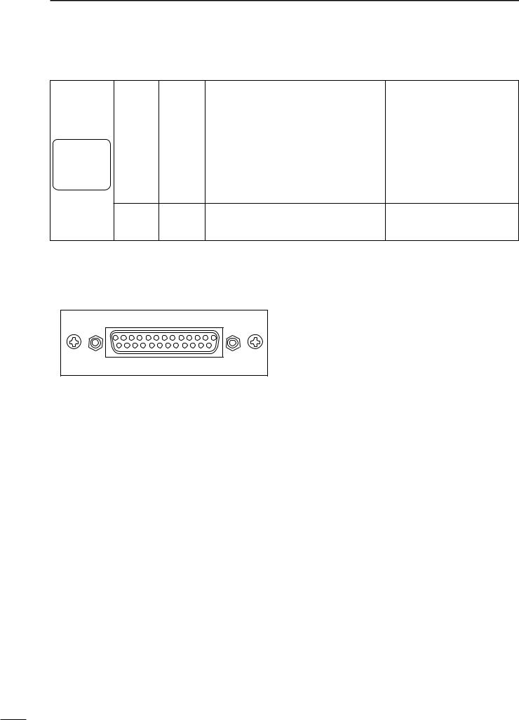
1 PANEL DESCRIPTION
DRemote connector
|
|
|
|
|
|
|
|
|
|
|
|
Pin No. |
Pin Name |
Description |
Specification |
|
|
|
|
|
|
|
|
|
|
|
1 |
–PTT |
Input terminals to transmit the repeater in rela- |
High voltage=PTT ON (transmits) |
|
|
|
|
|
|
|
|
|
|
|
|
tion to the external equipment. An opto-isolator |
||||
|
|
|
|
|
|
|
|
|
|
|
|
|
|
||
|
|
|
|
|
|
|
|
|
|
|
2 |
|
Hi-Z=PTT OFF |
||
|
|
|
|
|
|
|
|
|
|
|
+PTT |
is provided to facilitate PTT signals. |
|||
|
|
|
|
|
|
|
|
|
|
|
|
||||
|
|
|
|
|
|
|
|
|
|
|
|
|
|
|
|
|
|
|
|
|
|
|
|
|
|
|
3 |
–AFOUT |
Output terminal for AF signals from the AF de- |
Output impedance: 600 Ω |
|
|
|
|
|
|
|
|
|
|
|
|
|
|
|
tector circuit via the bandpass filter. Output level |
|
|
|
|
|
|
|
|
|
|
|
|
4 |
+AFOUT |
|||
|
q |
|
|
i |
is fixed, regardless of [AF] control. |
|
|||||||||
|
|
|
|
|
|
|
|
|
|
|
|
|
|
|
|
|
|
|
|
|
|
|
|
|
|
|
5 |
–EXTMOD |
Input terminal for the modulation circuit. |
Input impedance: 600 Ω |
|
|
|
|
|
|
|
|
|
|
|
|
|
|
|
||
|
|
|
|
|
|
|
|
|
|
|
|
|
|
||
|
|
|
|
|
|
|
|
|
|
|
|
|
|
||
6+EXTMOD
7–BUSY Output terminal for squelch condition
|
|
(Open/Close). An opto-isolator is provided to fa- |
Open collector=BUSY OFF |
|
8 |
+BUSY |
0 V=BUSY ON (Squelch is opened) |
||
cilitate BUSY signals. |
||||
|
DAccessory connector
!3 q
@5 !4
Pin No. |
Pin Name |
Description |
|
Specification |
|
1 |
BUSY OUT |
Output terminal for busy signal. |
Open collector=OFF, 0 V=ON |
||
|
|
|
|
||
2 |
COAXIAL SW |
Output terminal for coaxial switching (antenna switching) |
Open collector=OFF |
||
signal. |
0 V=ON |
||||
|
|
||||
|
|
|
|
|
|
3 |
M/S IN |
Input terminal for master/slave signal. |
+5 |
V pull up, Active=L |
|
|
|
|
|
|
|
4 |
D1 |
Input terminal for selecting memory channel. |
+5 |
V pull up, Active=L |
|
|
|
|
|
|
|
5 |
D3 |
Input terminal for selecting memory channel. |
+5 |
V pull up, Active=L |
|
|
|
|
|
|
|
6 |
EXT RPT/BASE |
Input terminal for repeater/base operating mode switching |
+5 |
V pull up |
|
signal. |
Active=L |
||||
|
|
|
|
|
|
7 |
EXT MONI |
Input terminal for monitor function. |
+5 |
V pull up, Active=L |
|
|
|
|
|
||
8 |
EXT DTCS |
Input terminal for continuous tone (CTCSS/DTCS) signal. |
Input impedance: 100 kΩ (approx.) |
||
|
|
|
|
||
9 |
EXTMOD IN B |
Input terminal for the modulation signals applied to input of |
Input impedance: 600 Ω (approx.) |
||
|
|
the splutter filter circuit. |
|
|
|
10 |
EXTMOD IN A |
Input terminal for the modulation signal applied to input of |
Input impedance: 600 Ω (approx.) |
||
|
|
the pre-emphasis circuit via the bandpass filter. |
|
|
|
|
|
Output terminal for AF signals from the AF detector circuit |
|
|
|
11 |
AF OUT |
via the bandpass filter. Output level is fixed, regardless of |
Output impedance: 1 kΩ (approx.) |
||
|
|
[AF] control. |
|
|
|
|
|
|
|
||
12 |
DISC OUT |
Output terminal for AF signals from the AF detector circuit. |
Output impedance: 1 kΩ (approx.) |
||
|
|
Output level is fixed, regardless of [AF] control. |
|
|
|
13 |
+15V |
Output terminal for +15V DC while in AC operation. (While in |
Output current: Less than 1 A |
||
|
|
DC operation, same as input DC.) |
|
|
|
14 |
TX OUT |
Output terminal for transmission state. |
Open collector=OFF, 0 V=ON |
||
|
|
|
|
|
|
3
 Loading...