


V90
Operating Manual
ENGLISH
bandg.com

Preface
Copyright © 2014 Navico. All rights reserved.
B&G® is a registered trademark of Navico
No part of this manual may be copied, reproduced, republished, transmitted or distributed for any purpose, without prior written consent of B&G Electronics. Any unauthorized commercial distribution of this manual is strictly prohibited.
B&G Electronics may find it necessary to change or end our policies, regulations, and special offers at any time. We reserve the right to do so without notice. All features and specifications subject to change without notice.
All screens in this manual are simulated.
For free owner’s manuals and the most current information on this product, its operation and accessories, visit our web site: www.bandg.com
Navico Holding AS is not responsible for any changes or modifications to the radio not expressly approved by Navico AS as the responsible entity for its compliance. Modifications could void the user’s authority to operate the radio.
Compliance statements
DISCLAIMER: It is the owner’s sole responsibility to install and use the instrument and peripheral components in a manner that will not cause accidents, personal injury or property damage. The user of this product is solely responsible for observing safe boating practices.
NAVICO HOLDING AS. AND ITS SUBSIDIARIES, BRANCHES AND AFFILIATES DISCLAIM ALL LIABILITY FOR ANY USE OF THIS PRODUCT IN A WAY THAT MAY CAUSE ACCIDENTS, DAMAGE OR THAT MAY VIOLATE THE LAW.
Governing Language: This statement, any instruction manuals, user guides and other information relating to the product (Documentation) may be translated to, or has been translated from,
another language (Translation). In the event of any conflict between any Translation of the Documentation, the English language version of the Documentation will be the official version of the
Documentation.
V90 Operating Manual |
| 3 |
This manual represents the V90 as at the time of printing. Navico Holding AS. and its subsidiaries, branches and affiliates reserve the right to make changes to specifications without notice.
IMPORTANT
1.DSC functions will not operate on the V90 until your MMSI has been entered.
2.The radio channels installed into this B&G VHF radio may vary from country to country depending upon the model and government or national communications authority regulations.
3.Navico recommends that you check the radio operating licensing requirements of your country before using this B&G VHF radio. The operator is solely responsible for observing proper radio installation and usage practices.
4.A DSC warning label is supplied with this B&G VHF radio. To comply with FCC regulations, this label must be affixed in a location that is clearly visible from the operating controls of this radio. Make sure that the chosen location is clean and dry before applying this label.
5.This radio is designed to generate a digital maritime distress call to facilitate search and rescue. To be effective as a safety device, this radio must be used only within the geographic range of a shorebased VHF marine Channel 70 distress and safety watch system. The geographic range may vary but under normal conditions is approximately 20 nautical miles.
MMSI and license information
You must obtain a user MMSI (Maritime Mobile Service Identity) and enter it into your V90 radio in order to use the DSC functions. Similarly for the Automatic Transmitter Identification System (ATIS) MMSI. Contact the appropriate authorities in your country. If you are unsure who to contact, consult your B&G dealer.
The user MMSI is a unique nine digit number, similar to a personal telephone number. It is used on marine transceivers that are capable of using DSC (Digital Select Calling).
Depending upon your location, you may need a radio station license for the V90 You may also need an individual operator’s license.
B&G recommends that you check the requirements of your national radio communications authorities before operating DSC functions.
4 | |
V90 Operating Manual |
RF emissions notice
This equipment complies with FCC radiation exposure limits set forth for an uncontrolled environment. This device’s antenna must be installed in accordance with provided instructions; and it must be operated with minimum 96 cm spacing between the antennas and all person’s body (excluding extremities of hands, wrist and feet) during operation. Further, this transmitter must not be co-located or operated in conjunction with any other antenna or transmitter.
FCC statement
This device complies with Part 15 of the FCC Rules. Operation is subject to the following two conditions: (1) this device may not cause harmful interference, and (2) this device must accept
any interference received, including interference that may cause undesired operation.
¼Note: This equipment has been tested and found to comply with the limits for a Class B digital device, pursuant to Part 15 of the FCC Rules. These limits are designed to provide reasonable protection against harmful interference in a normal installation. This equipment generates, uses and can radiate radio frequency energy and, if not installed and used in accordance with the instructions, may cause harmful interference to radio communications. However, there is no guarantee that interference will not occur in a particular installation. If this equipment does cause harmful interference to radio or television reception, which can be determined by turning the equipment off and on, the user is encouraged to try to correct the interference by one or more of the following measures:
•Reorient or relocate the receiving antenna.
•Increase the separation between the equipment and receiver.
•Connect the equipment into an output on a circuit different from that to which the receiver is connected.
•Consult the dealer or an experienced technician for help.
•A shielded cable must be used when connecting a peripheral to the serial ports.
V90 Operating Manual |
| 5 |
Industry Canada statement
This device complies with Industry Canada license-exempt RSS standard(s).
Operation is subject to the following two conditions: (1) this device may not cause interference, and (2) this device must accept any interference, including interference that may cause undesired operation of the devise.
Le présent appareil est conforme aux CNR d’industrie Canada applicables aux appareils radio exempts de licence.
L’exploitation est autorisée aux deux conditions suivantes : (1) l’appareil ne doit pa produire de brouillage, et (2) l’utilisateur de l’appareil doit accepter tout brouillage radioélectrique subi, même si le brouillage est susceptible d’en compromettre le fonctionnement.
Under Industry Canada regulations, this radio transmitter may only operate using an antenna of a type and maximum (or lesser) gain approved for the transmitter by Industry Canada. To reduce
potential radio interference to other users, the antenna type and its gain should be so chosen that the equivalent isotropically radiated power (e.i.r.p.) is not more than that necessary for successful communication.
Conformément à la réglementation d’Industrie Canada, le présent émetteur radio peut fonctionner avec une antenne d’un type et d’un gain maximal (ou inférieur) approuvé pour l’émetteur par Industrie Canada. Dans le but de réduire les risques de brouillage radioélectrique à l’intention des autres utilisateurs, il faut choisir le type d’antenne et son gain de sorte que la puissance isotrope rayonnée quivalente (p.i.r.e.) ne dépassepas l’intensité nécessaire à l’établissement d’une communication satisfaisante.
Notice specific to the H50 handset
This ISM device complies with Canadian ICES-001.
Maintain a minimum separation of 2.5 cm (1 inch) from the face.
Cet appareil ISM est conforme à la norme NMB-001 du Canada.
Maintenir une distance minimum de 2,5 cm (1 inch) de la surface.
6 | |
V90 Operating Manual |
CE compliance statement
This product complies with CE under R&TTE directive 1999/5/EC. The relevant Declaration of Conformity is available in the following website under the model documentation section:
http://www.bandg.com
Important safety information
Read carefully before installation and use
Warning: Indicates a potentially hazardous situation that could result in death or serious injury.
Caution: Indicates a potentially hazardous situation that could result in minor or moderate injury.
V90 Operating Manual |
| 7 |

Contents
11About this manual
12System overview
12Introduction
13V90 Transceiver
14System overview diagram
16 Getting started
16 Handsets
19Handset control buttons
20Keys
21Switching on and off
23 The standby screen
23Modes
24Changing channel
26Adjusting the volume
26Adjusting squelch
27Setting transmission power
27PTT key
28Using the menus
28Shortcut keys
29Entering data
29Warning messages
29Alert tones
30 Operating procedures
30Making a routine radio call
30Calling a buddy
31Making a channel 16/9 distress call
31Making a DSC distress call
32Receiving weather alerts (US model only)
32Receiving SAME alerts (US model only)
33Favorite channel (non-US models)
34Three favorite channels 3CH
34 Scanning channels
37Using the hailer
38Using the fog horn
8 | |
Contents | V90 Operating Manual |
39 Using the intercom
39Using the announce function
40Using the voice recorder
40Sharing NMEA 2000 data
41Waypoint procedures
41Adding a new waypoint
42Editing a waypoint
42Deleting a waypoint
43Navigating to a waypoint
45 DSC procedures
45 Introduction to DSC
47 DSC distress calls
51 Sending routine DSC calls
63 Receiving DSC calls
69ATIS
70AIS procedures
71List of nearby vessels
71PPI display
72T/CPA screen
73AIS target information
74Setup
74Wireless handset setup
75Buddy list setup
77 Radio setup
84 DSC setup
91 AIS setup
94 GPS setup
97 General setup
99 Appendices
99Appendix 1 - Troubleshooting
100Appendix 2 - Keys reference
103Appendix 3 - Shift keys
104Appendix 4 - Screen symbols
105Appendix 5 - Beep tones and call alerts
105Appendix 6 - Warning messages
Contents | V90 Operating Manual |
| 9 |
106 |
Appendix 7 |
- Features |
108 |
Appendix 8 |
- DSC information |
108 |
Appendix 9 |
- AIS information |
110 |
Appendix 10 |
- Technical specification |
114 |
Appendix 11 |
- US and ROW VHF marine channel charts |
122 |
Appendix 12 |
- EU VHF marine channel charts |
128 |
Appendix 13 - MMSI and license information |
|
10 | |
Contents | V90 Operating Manual |
1 About this manual
This manual describes the operation of the B&G V90 marine VHF radio.
For instructions on installing the radio, please see the separate manual: B&G V90 Marine VHF radio Installation Manual.
This manual is organized as follows:
•System Overview
Describes the components and main features of the VHF radio.
•Getting started
Explains how to use the equipment, including handsets and menus.
•Operating procedures
Explains common radio operations, such making a VHF call to a shore station or another vessel.
•Waypoints DSC
AIS
These sections explain how to use these more advanced features.
•Setup
Tasks you need to do initially when setting up, and thereafter from time to time when you need to change a setting.
•Appendices
Reference sections, including trouble shooting guide, VHF channel frequencies and technical data.
¼Note: Different configurations of the V90 marine VHF radio are provided for different countries, depending on the VHF radio regulations of each country.
About this manual | V90 Operating Manual |
| 11 |

2 System overview
Introduction
The B&G V90 VHF radio is a comprehensive solution for marine VHF radio applications.
The radio comprises:
•V90 VHF transceiver.
•One wired handset as standard, and optionally up to 3 more wired handsets. (Maximum of 4 wired handsets in total.)
•Up to 2 optional wireless handsets.
•Up to 4 optional external speakers.
In addition to routine ship-to-ship or ship-to-shore VHF communications, the V90 has many advanced features, including:
•NMEA 2000 and NMEA 0183 network connectivity, which allows the radio to share information with other onboard devices, such as a GPS antenna, a chartplotter or a multi-function display.
•Digital Selective Calling (DSC) for automated distress calls, and for calling individual vessels using their Maritime Mobile Service Identity (MMSI). Also includes a track buddy function.
•Automatic Identification System (AIS) for monitoring nearby vessels (receive only).
•Automatic Transmitter Identification System (ATIS) function for controlled VHF communications in European inland waterways (EU models).
•Automatic weather alert using TONE and SAME systems (US models).
•Monitoring multiple VHF channels simultaneously (country specific).
•Intercom calls between handsets.
•Voice recording.
•Fog horn and loud-hailer modes.
•Horn button connection.
•Up to three instant favorite channel selections.
For detailed features and specifications, see “Appendix 10 -
Technical specification” on page 110.
12 | |
System overview | V90 Operating Manual |

V90 Transceiver
System overview | V90 Operating Manual |
| 13 |

System overview diagram
10 |
|
9 |
|
|
1 |
+ |
2 |
8 |
|
||
12 VDC |
|
|
|
|
|
|
|
7 |
|
|
6 |
|
|
4 |
|
|
5 |
3 |
|
|
14 | |
|
System overview | V90 Operating Manual |
System overview diagram - legend
1V90 VHF radio transceiver
212 VDC power supply
3Wireless handset
4Wired handset
5External loudspeaker
6NMEA 0183 GPS and horn button
7AIS data output
8Loud hailer speaker
9VHF antenna
10NMEA 2000 network connection
System overview | V90 Operating Manual |
| 15 |

3 |
|
Getting started |
|
|
|
|
|
|
|
|
|
|
|
Caution: Under extreme operating conditions, the |
|
|
|
temperature of the rear heat-sink on this radio may |
|
|
|
exceed normal surface temperatures. |
|
|
|
Caution is advised to prevent possible skin burns. |
|
Handsets
All the operating functions of the V90 are carried out using the handsets. Each handset contains a microphone, a small internal loudspeaker and various buttons for controlling the radio.
Two types of handset are available:
•Up to four wired handsets can be connected. There must be at least one wired handset connected to the station one terminal in the installation.
•Up to two wireless handsets can be installed. The wireless handsets communicate with the transceiver by 2.4 GHz radio communication. The wireless handsets are powered by internal rechargeable batteries, and are charged by inductive charging when on the cradle.
When there are multiple handsets, they are synchronized so that there is no conflict of operation and they each display the same information on their screens.
Handset naming
Handset names appear on screen at times—for example, when another handset has control of the radio.
Wired handsets HS1, HS2, HS3, HS4
The above handsets—1 standard and 3 optional—are connected to the transceiver. The volume controls on these handsets control the corresponding external speakers.
16 | |
Getting started | V90 Operating Manual |

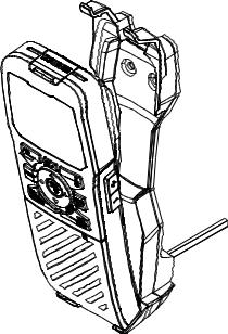
Handset parts
1
2
3 


 4
4
5
6
1Red distress cover with button beneath
2Screen
3PTT button
4Volume control
5Function keys
6Keypad (wired handsets only).
Subscribing a wireless handset
At installation time, wireless handsets must be registered in the transceiver. For instructions, see “Subscribing a wireless handset” on page 74.
Getting started | V90 Operating Manual |
| 17 |
Charging a wireless handset
When a wireless handset is not in use, it should be placed on its cradle for charging.
Locate the bottom of the handset onto the cradle first, and then press the top of the handset inwards until it clicks into the top lugs.
Handset operation priority
If you want to use HS1, but it displays “HS# IN USE,” it means that another handset is operating.
To shift control to HS1:
1.Press [X].
2.The display shows “Take Control?”
•Press [OK] to take over control.
•Or, [X] to leave the other handset in control.
18 | |
Getting started | V90 Operating Manual |
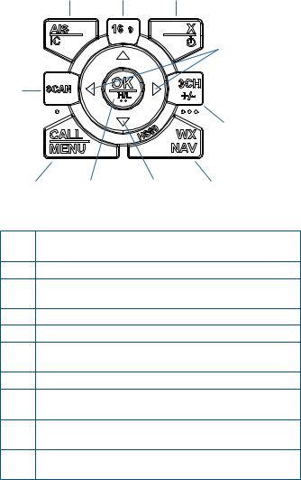
Handset control buttons
1 2 3
|
|
|
4 |
10 |
|
|
|
|
|
|
5 |
9 |
8 |
7 |
6 |
1 |
Short press for AIS menu. |
|
|
|
Long press for Hailer mode. |
|
|
2 |
Press to select the priority channel. |
|
|
3 |
Short press for Exit key. |
|
|
|
Long press for power on/off. |
|
|
4 |
Squelch keys. Also used for moving cursor left/right. |
||
5 |
Three favorite channel key. |
|
|
6 |
Short press for weather station (US models). |
||
|
Long press for Navigation mode. |
|
|
7 |
Change channel, or scroll menu options. |
||
8 |
Short press for [OK] key. |
|
|
|
Long press to toggle high/low power. |
||
9 |
Short press for DSC menu. |
|
|
|
Long press for menu. |
|
|
10 |
Short press to start dual-watch or tri-watch mode. |
||
|
Long press to start scanning channels. |
||
For more information on keys, see “Appendix 2 - Keys reference” on page 100.
Getting started | V90 Operating Manual |
| 19 |

Keys
Some keys on the handsets have more than one function, depending on what mode the radio is in. For example, [OK] for accepting input and [H/L] for selecting high or low transmission power are activated using the same key. To activate the lower function on the key label, press and hold the key until the radio responds.
A complete reference to keys is given in “Appendix 2 - Keys reference” on page 100.
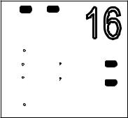
Softkeys
A softkey is a name that appears at the bottom of the screen, and that can be selected using the [SCAN] and/or [OK] and/or [3CH] keys during DSC operations.
Dot symbols on the handset keys and just under the display screen indicate which keys correspond to the softkeys as follows:
|
• |
|
|
• • |
• • • |
|
[SCAN] key |
[OK] key |
[3CH] key |
||
Hi |
|
16PRI |
|
|
|
DSCC |
|
|
|
||
ROUTINE FROM |
|
|
|||
SUNBIRD |
|
|
|
|
|
NO AUTO SW |
|
|
|
|
|
CH09 REQUEST |
|
|
|
|
|
|
01:15 |
USA |
|
|
|
NEW-CH |
ABLE |
|
|
|
|
|
|
|
|
||
SI C |
|
|
|
|
|
In the illustration above, you would press [SCAN] for NEW-CH (request new channel), or [OK] for ABLE (accept proposed channel).
The use of these keys is further explained in the DSC section of this manual.
20 | |
Getting started | V90 Operating Manual |
Switching on and off
Switching on the system
The VHF radio is switched on from a wired handset.
To switch on the radio:
1.Press and hold [X] on a wired handset until the startup screen showing version numbers appears.
2.When prompted, press [X] to exit the startup screen and display the main operating screen.
This switches on the transceiver and the wired handset.
¼Note: A wireless handset can only switch itself on and off. See “Switching on a wireless handset” on page 22.
Switching off the system
The system is switched off by holding down the [X] key on a wired handset until the display shows “Release the key to power off.”
Just one handset
1.In standby mode, press [X] on the wired handset until the display shows “Release key to power off.”
2.Release the [X] key.
More than one wired handset
HS1 (handset 1) has a power-off menu. All the other handsets simply power themselves off.
Handset 1 power-off menu:
•SYSTEM
Turns off all handsets and the transceiver.
•HS1
Turns off the handset itself.
Displays “SYSTEM IS WORKING” with no backlight.
¼Note: You can ignore the power-off menu and keep holding down [X] until the display shows “Release the key to power off.”
Getting started | V90 Operating Manual |
| 21 |

Switching on a wireless handset
•Press and hold [X] until the display illuminates.
The display shows “Searching,” then “Connecting,” and then the current operating screen.
¼Notes:
•This only switches on the individual wireless handset, not the transceiver.
•If the transceiver is off, the wireless handset continues to display “Searching.”
•At install time, wireless handsets must be subscribed. See “Subscribing a wireless handset” on page 74.
Switching off a wireless handset
¼Note: This procedure only switches off the wireless handset. It does not switch off any other handsets or the transceiver.
1.Press and hold [X] until the following message appears: “Release key to power off.”
2.Release the [X] key.
Handset status display
A small icon located on the lower right of the screen shows the status of all connected handsets.
This handset is
Handset online
Wireless
The above example shows that handset 1 and handset 3 are online and this handset is handset 1.
22 | |
Getting started | V90 Operating Manual |
The standby screen
The following illustration shows a typical operating screen in standby mode. The radio is in standby mode when it is waiting to send or receive calls.
Hi |
DSC |
16 |
|
DISTRESS |
|||
14:43 UTC |
|||
128t |
5Kt |
PRI |
|
55 |
33.122 N |
||
|
|||
012 |
42.408 E |
INT |
|
HARBR |
0.00 |
||
275 t |
8.00m |
||
|
n |
|
|
The above screen shows:
•The radio is tuned to channel 16, which has been designated as the priority channel (PRI).
•In this unit, Channel 16 has been named “DISTRESS.”
•Transmitting power is set to high (Hi).
•DSC is enabled.
•The time is 14:43 UTC.
•The current course is 128° true and speed over ground is 5.0 knots.
•The current latitude is 55°33.122’N and longitude 012°42.408’E.
•The channel bank selected is International (INT).
•The name of the destination waypoint is HARBR. It is 8 nautical miles away at a bearing of 275° true.
Modes
The V90 has several different modes of operation. The main mode is standby mode, during which the radio is ready to send or receive VHF calls. Generally, pressing the [X] key will exit any special mode and return to standby mode.
Getting started | V90 Operating Manual |
| 23 |
Scanning mode
In scanning mode, the radio scans selected channels for radio activity.
Navigation mode
Navigation mode displays distance and bearing to a selected waypoint.
Hailer mode
Hailer mode allows you to use the radio to hail other vessels or deck crew through a connected loud-hailer speaker.
Fog horn mode
Fog horn mode allows you to use the radio to sound a fog horn tone through a connected loud-hailer speaker.
Intercom mode
Intercom mode allows you to use the handsets to communicate from one handset to the others in your vessel.
Standby Mode
In standby mode, the V90 displays the main operating screen on the handset(s) and is ready to send or receive calls on the selected channel.
Changing channel
Different jurisdictions in the world have allocated different sets of VHF radio channels for different purposes. These sets are known as channel banks. The available channel banks and their corresponding channels are given in “Appendix 11 - US and ROW VHF marine channel charts” on page 114.
Normally the radio should be left tuned to the priority channel (CH16 or CH09) in case an emergency call is broadcast on that channel. The V90 can also be set to monitor several channels at the same time. In this case, the radio continuously scans the selected channels and, if activity is heard on a channel, it will switch to that channel while the activity continues. Then it will revert to scanning. See “Scanning channels” on page 34.
24 | |
Getting started | V90 Operating Manual |

You can use one of the following methods to change channel:
•Press [16/9] to switch immediately to the priority channel (see “Priority channels” below).
•Press ▲or ▼until you reach the required channel number.
•Press and hold ▲or ▼to rapidly scroll through the channel numbers. When the number you require is displayed, release the key.
•Input the number on the keypad (wired handset only), and when the required channel number is flashing on screen, press [OK], or wait for 2 seconds for the number to be accepted automatically. When entering a single-digit channel number, prefix the channel number with 0.
•Repeat press [3CH] to scroll through your three favorite channels. See “Three favorite channels 3CH” on page 34.
•Press [WX] and then ▲or ▼to tune to a weather station (US model only). See “Receiving weather alerts (US model only)” on page 32.
•Press [WX] to go directly to a set favorite channel (EU models only).
Priority channels
Channel 16 is the international emergency priority channel. On Channel 16, operators must give priority to any emergency
calls occurring on that frequency. In the US, Channel 9 is also an emergency priority channel.
To switch directly to Channel 16 (or Channel 9 if configured):
•Press the 16/9 button.
16 / 9
¼Note: The default emergency channel is CH16. On US models of the radio, you can change the default emergency channel to CH9 by holding down 16/9 until the unit beeps and displays 09. Repeat the procedure to change back to CH16 as the default emergency channel.
Getting started | V90 Operating Manual |
| 25 |
Special channel A/B
Certain USA channels have ‘A’ or ‘B’ suffixes.
“A” indicates simplex use of the ship station transmit side of an international duplex channel, and that operations are different than international operations on that channel. “A” channels are generally only used in the United States, and use is normally not recognized or allowed outside the U.S. “B” indicates simplex use of the coast station transmit side of an international duplex channel. The U.S. does not currently use “B” channels for simplex communications in this band.
Adjusting the volume
The volume control on the right hand side of the handset provides up and down control of the handset speaker volume and the external speaker volume.
Adjusting squelch
The squelch adjustment allows you to adjust the sensitivity of the radio so that background noise is minimized. In areas of high
static noise, such as close to large cities, you can improve quality of reception by adjusting the squelch.
•Use the ◄and ►keys to adjust the level up or down respectively.
•Adjust the level until the background noise just disappears.
¼ Notes:
•You can also adjust the sensitivity of the VHF receiver using the Local/Distance setting. See “Radio sensitivity” on page 97.
•The ◄and ►keys are also used for moving the cursor when entering data on a wired handset.
26 | |
Getting started | V90 Operating Manual |
Setting transmission power
The V90 has two transmission power settings:
High 25 W
Low 1 W
To change the power setting:
Press and hold [H/L] until the Hi or Lo icon on the display changes.
¼ Notes:
•Channel 16 always remains in high transmission power.
•Some channels allow only low-power transmissions. If you try to change to high power, the V90 will sound an error beep.
•Some channels allow only low power transmissions initially, but can be forced to high power by holding down [H/L] and PTT at the same time.
•See “Appendix 11 - US and ROW VHF marine channel charts” on page 114 for a list of channel data.
PTT key
The Push to Talk (PTT) key activates the microphone and transmits your voice over the selected channel.
¼ Notes:
•Pressing PTT while a menu is displayed will exit the menu without making any selection.
•DSC transmission has higher priority than PTT voice transmission.
•During PTT transmission, the radio cannot receive a DSC call.
•If PTT gets stuck or accidentally held in the talk position, a built-in timer sounds an error beep and shuts down the transmission after 5 minutes.
Getting started | V90 Operating Manual |
| 27 |

Hi
DSCC
DSC SETUP  USER MMSI GROUP SETUP INDIV REPLY DSC FUNC
Hi
DSCC
MENU SELECT  WAYPOINT N2K DATA VOICE REC BACKLIGHT
PRI
USA
16
PRI
USA
28 |
•Short press to access the DSC menu.
•Long press (press and hold) to access the main menu.
To use the menus:
•Use ▼or ▲to scroll to the option you want.
•Press [OK] to select a menu option, or
•Press [X] to go back without selecting an option.
¼Note: If the radio is left in menu mode, after a default time of 10 minutes, it beeps a warning and then automatically returns to standby mode.
Shortcut keys
The V90 wired handset keypad includes a SHIFT key that modifies the function of some keys.
•Press [SHIFT] to display the shift icon (S), and then press the number key to access the required function.
Some menu items can be accessed via shortcut keys.
For a list of shortcut keys, see “Appendix 3 - Shift keys” on page 103.
Getting started | V90 Operating Manual
Entering data
Entering data with a wired handset
Enter data using the keypad. The first press of a key inputs the number corresponding to the key; subsequent presses input letters of the alphabet as indicated on the key. For example, 2, A, B, and C are typed using the same key.
After a short pause, the cursor automatically jumps to the next space; or, you can press [OK] to move to the next space immediately.
¼Note: Characters can only be entered in upper case.
To replace a character:
•Use the ◄and ►keys to move the cursor to the character. You can then type over the character.
To finish entering data:
Press [OK] repeatedly to reach the end of the line. The cursor will then move to the next input required, or a save/cancel option will be displayed for you to select as required.
¼Note: You can press [X] at any time to go back one step.
Entering data with a wireless handset
Use the ▲and ▼keys to scroll through the available characters, and then press [OK] to select the required character.
Warning messages
See “Appendix 6 - Warning messages” on page 105.
Alert tones
See “Appendix 5 - Beep tones and call alerts” on page 105.
Getting started | V90 Operating Manual |
| 29 |

4 |
Operating procedures |
Making a routine radio call |
|
Making a routine ship to ship or ship to shore call. |
1.Select a calling channel.
See “Changing channel” on page 24.
2.Listen to make sure that there is no traffic on the channel.
3.Hold down [PTT] and announce the station you want to contact and your own vessel’s details. When you have finished speaking, say “Over” and then release [PTT].
4.When you receive a reply on the calling channel, agree a working channel.
5.Change to the working channel.
6.Continue the conversation:
•Hold down [PTT] while you are speaking.
•Release [PTT] while you are listening.
7. When finished, press [16/9] to return to the radio watch channel.
¼Note: When you call a coast station, the coast station operator normally states a suitable working channel.
Calling a buddy
You can call a buddy using their MMSI on the DSC system. For further information, see “Introduction to DSC” on page 45.
30 | |
Operating procedures | V90 Operating Manual |
 Loading...