


INSTRUCTION MANUAL
VHF MARINE TRANSCEIVER
iM401EURO

IN CASE OF EMERGENCY
If your vessel requires assistance, contact other vessels and the Coast Guard by sending a distress call on Channel 16.
USING CHANNEL 16
DISTRESS CALL PROCEDURE
1.“MAYDAY MAYDAY MAYDAY.”
2.“THIS IS ...............” (name of vessel)
3.Your call sign or other indication of the vessel (AND 9-digit DSC ID if you have one).
4.“LOCATED AT ...............” (your position)
5.The nature of the distress and assistance required.
6.Any other information which might facilitate the rescue.
Or, transmit your distress call using digital selective calling on Channel 70 (the optional DS-100 (#02) must be installed).
USING DIGITAL SELECTIVE CALLING (ch 70)
(DS-100 DSC CONTROLLER is required)
DISTRESS CALL PROCEDURE
1.Push and hold [DISTRESS] on the DS-100 for 5 sec. until you hear 5 short beeps change to one long beep.
2.Wait for an acknowledgment from a coast station.
• Channel 16 is automatically selected.
3.Push and hold [PTT], then transmit the appropriate information as at left.
Versions of the IC-M401EURO which display the “CE” symbol on the serial number seal, comply with the essential requirements of the European Radio and Telecommunication Terminal Directive 1999/5/EC. ò This warning symbol indicates that this equipment operates in non-harmonised frequency bands and/or may be subject to licensing conditions in the country of use. Be sure to check that you have the correct version of this radio or the correct programming of this radio, to comply with national licensing requirement.
Icom, Icom Inc. and the 
 logo are registered trademarks of Icom Incorporated (Japan) in the United states, the United Kingdom, Germany, France, Spain, Russia and/or other countries.
i

INSTALLATION NOTES
The installation of this equipment should be made in such a manner as to respect the EC recommended electromagnetic field exposure limits (1999/519/EC).
The maximum RF power available from this device is 25 watts. The antenna should be installed as high as possible for maximum efficiency and that this installation height should be at least 5 meters above ground (or
accessible) level. In the case where an antenna cannot be installed at a reasonable height, then the transmitter should neither be continuously operated for long periods if any person is within 5 meters of the antenna, nor operated at all if any person is touching the antenna.
In all cases any possible risk depends on the transmitter being activated for long periods.
(actual recommendation limits are specified as an average of 6 minutes) Normally the transmitter is not active for long periods of time. Some radio licenses will require that a timer circuit automatically cuts the transmitter after 1–2 minutes etc.
Similarly some types of transmitter, SSB, CW, AM, etc. have a lower ‘average’ output power and the perceived risk is even lower.
TABLE OF CONTENTS
1 |
OPERATING RULES .......................... |
1 |
2 |
PANEL DESCRIPTION .................. |
2 – 4 |
|
■ Panel description ............................. |
2 |
|
■ Function display ............................... |
3 |
|
■ Microphone ...................................... |
4 |
3 |
BASIC OPERATION ...................... |
6 – 9 |
|
■ Channel selection ............................ |
6 |
|
■ Receiving and transmitting .............. |
8 |
|
■ Call channel programming ............... |
9 |
|
■ Memory channel names .................. |
9 |
4 |
DUALWATCH/TRI-WATCH ......... |
10–11 |
|
■ Description ..................................... |
10 |
|
■ Operation ....................................... |
10 |
5 |
SCAN OPERATION ................... |
12 – 13 |
|
■ Scan types ..................................... |
12 |
|
■ Setting tag channels ...................... |
13 |
|
■ Starting a scan ............................... |
13 |
6 |
SET MODE ................................. |
14 – 15 |
|
■ Set mode programming ................. |
14 |
|
■ Set mode items .............................. |
15 |
7 |
CONNECTIONS AND |
|
|
MAINTENANCE ......................... |
16 – 20 |
|
■ Unpacking ...................................... |
16 |
|
■ Antenna ......................................... |
16 |
|
■ Fuse replacement .......................... |
16 |
|
■ Cleaning ......................................... |
16 |
|
■ Connections ................................... |
17 |
|
■ Mounting the transceiver ............... |
18 |
|
■ Dimensions ..................................... |
20 |
8 |
TROUBLESHOOTING ...................... |
22 |
9 |
CHANNEL LIST ................................ |
23 |
10 SPECIFICATIONS AND OPTIONS ... |
24 |
|
|
■ Specifications ................................. |
24 |
|
■ Options .......................................... |
24 |
|
MB-69 TEMPLATE |
|
ii

IMPORTANT
READ ALL INSTRUCTIONS carefully and completely before using the transceiver.
SAVE THIS INSTRUCTION MANUAL — This instruction manual contains important operating instructions for the IC-M401EURO.
CAUTION
RWARNING! NEVER connect the transceiver to an AC outlet. This may pose a fire hazard or result in an electric shock.
NEVER connect the transceiver to a power source of more than 16 V DC or using reverse polarity. This will ruin the transceiver.
NEVER cut the DC power cable between the DC plug and fuse holder. If an incorrect connection is made after cutting, the transceiver may be damaged.
NEVER place the transceiver where normal operation of the vessel may be hindered or where it could cause bodily injury.
KEEP the transceiver at least 1 m away from the ship’s navigation compass.
DO NOT use or place the transceiver in areas with temperatures below –20°C or above +60°C or, in areas subject to direct sunlight, such as the dashboard.
AVOID the use of chemical agents such as benzine or alcohol when cleaning, as they may damage the transceiver surfaces.
BE CAREFUL! The transceiver rear panel will become hot when operating continuously for long periods.
Place the transceiver in a secure place to avoid inadvertent use by children.
After exposure to salt water, clean the transceiver thoroughly with fresh water to avoid corrosion.
•Do not pour water on the transceiver under the water tap directly.
iii

PRIORITIES
•Read all rules and regulations pertaining to priorities and keep an up-to-date copy handy. Safety and distress calls take priority over all others.
•You must monitor Channel 16 when you are not operating on another channel.
•False or fraudulent distress signals are prohibited and punishable by law.
PRIVACY
•Information overheard but not intended for you cannot lawfully be used in any way.
•Indecent or profane language is prohibited.
RADIO LICENSES
(1) SHIP STATION LICENSE
You must have a current radio station license before using the transceiver. It is unlawful to operate a ship station which is not licensed.
Inquire through your dealer or the appropriate government agency for a Ship-Radiotelephone license application. This government-issued license states the call sign which is your craft’s identification for radio purposes.
OPERATING RULES 1 
(2) OPERATOR’S LICENSE
A Restricted Radiotelephone Operator Permit is the license most often held by small vessel radio operators when a radio is not required for safety purposes.
The Restricted Radiotelephone Operator Permit must be posted or kept with the operator. Only a licensed radio operator may operate a transceiver.
However, non-licensed individuals may talk over a transceiver if a licensed operator starts, supervises, ends the call and makes the necessary log entries.
Keep a copy of the current government rules and regulations handy.
1
 2 PANEL DESCRIPTION
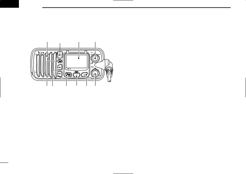
■ Panel description
Speaker i Function display q
TAG

 iC-m401euro
CALL
u y t r e w
qPOWER/VOLUME CONTROL [VOL]
Turns power ON and OFF and adjusts the audio level. (p. 8)
wSQUELCH CONTROL [SQL]
Sets the squelch threshold level. (p. 8)
eTRANSMIT POWER SWITCH [H/L]
Toggles high and low power when pushed. (p. 8)
•Some channels are set to low power only.
While pushing this switch, other switches perform secondary functions.
rCHANNEL/DUALWATCH/TRI-WATCH SWITCH [CH]
Exits from Channel 16 or call channel when pushed. (p. 6)
While pushing [H/L], selects channel group when pushed. (p. 7)
•The European version has International channels only and this function is not available.
Starts dualwatch or tri-watch when pushed for 1 sec.
Stops dualwatch/tri-watch when either is activated. t CHANNEL 16/CALL CHANNEL SWITCH [16]
Selects Channel 16 when pushed. (p. 6)
Selects call channel when pushed for 1 sec. (p. 6)
•“CALL” appears when call channel is selected.
Push for 3 sec. to enter call channel programming condition when call channel is selected. (p. 9)
While pushing [H/L], enters memory channel name programming condition. (p. 9)
Enters set mode when pushed while turning power ON. (p. 14)
yCHANNEL UP/DOWN SWITCHES [Y]/[Z]
Push to select the operating channels, set mode contents, etc.
While pushing [H/L], push [Y]/[Z] to adjust the brightness of the LCD and switch backlight.
uSCAN SWITCH [SCN] (p. 13)
Starts and stops normal or priority scan when tag channels are programmed.
iTAG CHANNEL SWITCH (p. 13)
Push [TAG] to set the displayed channel as a tag (scanned) channel.
While pushing [H/L], push for 3 sec. to clear all tag channels.
2

■ Function display
!0 |
q w |
|
e |
|
r |
|
t |
|
y |
|
u |
o |
i |
|
qTRANSMIT INDICATOR (p. 8)
“TX” appears while transmitting.
wBUSY INDICATOR (p. 8)
“BUSY” appears when receiving a signal or when the squelch opens.
eTAG CHANNEL INDICATOR (p. 13) Appears when a tag channel is selected.
r CALL CHANNEL INDICATOR
“CALL” appears when the call channel is selected. (p. 6)
t LOW POWER INDICATOR (p. 8)
“LOW” appears when low power is selected.
PANEL DESCRIPTION 2
yATIS INDICATOR
“ATIS” appears when the ATIS encoder is activated.
•The ATIS encoder is available for Germany and Holland versions only.
uDUPLEX INDICATOR (p. 7)
Appears when a duplex channel is selected.
iCHANNEL NAME INDICATOR
Memory channel name appears if programmed. (p. 9)
“ 


 ” scrolls when the battery voltage drops to approx. 10 V DC or below.
“ 


 ” appears during dualwatch; “

 ” appears during triwatch. (p. 10)
oCHANNEL GROUP INDICATOR (p. 7)
Indicates whether an International (I) or U.S.A (U) channel is selected.
• USA channel group is available for U.K. and Italy versions only.
!0CHANNEL NUMBER READOUT
Indicates the selected operating channel number.
• “A” appears when a simplex channel is selected. (p. 7)
In set mode, indicates the selected condition. (p. 15)
3

2 PANEL DESCRIPTION
■ Microphone
q
 Microphone w
 e
e
qPTT SWITCH [PTT]
Push and hold to transmit; release to receive. (p. 8)
wCHANNEL UP/DOWN SWITCHES [Y]/[Z]
Push either switch to change the operating memory channel, set mode contents, etc.
eCHANNEL 16/CALL CHANNEL SWITCH [16/C]
Same as the [16] switch on the front panel. (p. 2)
Selects Channel 16 when pushed. (p. 6)
Selects call channel when pushed for 1 sec. (p. 6)
•“CALL” appears when call channel is selected.
Push for 3 sec. to enter call channel programming condition when call channel is selected. (p. 9)
While pushing [H/L], enters memory name programming condition. (p. 9)
• Microphone lock function
The microphone lock function electrically locks the [Y]/[Z] and [16/C] switches on the microphone. This prevents accidental channel changes and accidental function access.
While pushing [16] on the microphone, turn power ON to toggle the microphone lock function ON and OFF.
4

Blank page
5
 3 BASIC OPERATION
■ Channel selection
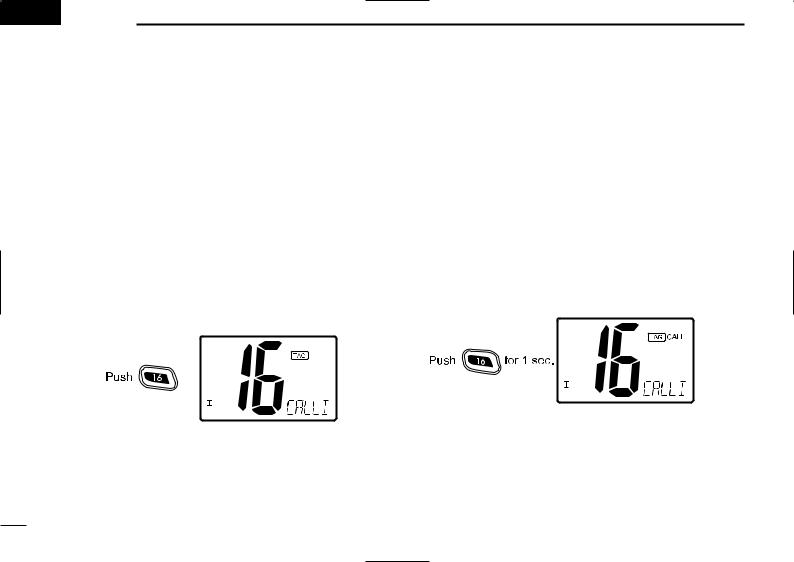
Channel 16
Channel 16 is the distress and safety channel. It is used for establishing initial contact with another station and for emergency communications. Channel 16 is monitored during both dualwatch and tri-watch. While standing by, you must monitor Channel 16.
Push [16] momentarily to select Channel 16.
•Output power turns to “25W” automatically, whenever Channel 16 is selected. For example, when selecting Channel 16 via the dial, dualwatch/tri-watch or a scan stops at Channel 16, etc.
Push [CH] to return to the condition before selecting Channel 16, or push [Y]/[Z] to select an operating channel.
Call channel
Each regular channel group has a separate leisure-use call channel. The call channel is monitored during tri-watch. The call channels can be programmed (p. 9) and are used to store your most often used channels in each channel group for quick recall.
Push [16] for 1 sec. to select the call channel of the selected channel group.
•“CALL” and call channel number appear.
•Each channel group may have an independent call channel after changing a call channel. (U.K. version only)
Push [CH] to return to the condition before selecting call channel, or push [Y]/[Z] to select an operating channel.
6
 Loading...