


INSTRUCTION MANUAL
VHF MARINE TRANSCEIVER
iC-m59

IN CASE OF EMERGENCY
If your vessel requires assistance, contact other vessels and the Coast Guard by sending a distress call on channel 16.
USING CHANNEL 16
DISTRESS CALL PROCEDURE
1.“MAYDAY MAYDAY MAYDAY”
2.“THIS IS - - - - - - - - - - - - - - ” (name of vessel)
3.Your call sign or other indication of the vessel (AND 9-digit DSC ID if you have one).
4.“LOCATED AT - - - - - - - - - - ” (your position)
5.The nature of the distress and assistance required.
6.Any other information which might facilitate the rescue.
Or, transmit your distress call using digital selective calling on channel 70 (the optional UX-120 DSC UNIT must be installed).
USING DIGITAL SELECTIVE CALLING (ch 70)
(UX-120 required)
DISTRESS CALL PROCEDURE
1.Push and hold [16•EMER] for 5 sec. until you hear 5 short beeps change to one long beep.
2.Then, push [PTT] to transmit the call.
3.Wait for an acknowledgment from a coast station.
• When received, channel 16 is automatically selected.
4.Push and hold [PTT], then transmit the appropriate information as at left.
i

TABLE OF CONTENTS
IN CASE OF EMERGENCY .................................................. |
i |
|
TABLE OF CONTENTS ...................................................... |
ii |
|
IMPORTANT ...................................................................... |
iii |
|
CAUTIONS.......................................................................... |
iii |
|
1 OPERATING RULES ..................................................... |
1 |
|
2 |
PANEL DESCRIPTION ............................................ |
2 – 5 |
|
■ Front panel ................................................................. |
2 |
|
■ Microphone ................................................................. |
3 |
|
■ Function display .......................................................... |
4 |
3 |
BASIC OPERATION .............................................. |
6 – 11 |
|
■ Power ON ................................................................... |
6 |
|
■ Channel selection ....................................................... |
6 |
|
■ Receiving .................................................................... |
8 |
|
■ Transmitting ................................................................ |
9 |
|
■ Scan function ............................................................ |
10 |
|
■ Call channel programming ........................................ |
11 |
|
■ Display backlighting .................................................. |
11 |
4 |
DIGITAL SELECTIVE CALLING ......................... |
12 – 18 |
|
■ General ..................................................................... |
12 |
|
■ Distress call transmission ......................................... |
13 |
|
■ All ships call transmission ......................................... |
14 |
|
■ Individual call transmission ....................................... |
15 |
|
■ Receiving DSC calls ................................................. |
16 |
5 |
SET MODE ........................................................... |
19 – 21 |
|
■ Entering SET mode .................................................. |
19 |
|
■ SET mode items ....................................................... |
19 |
6 |
CONNECTIONS AND MAINTENANCE .............. |
22 – 27 |
|
■ Unpacking ................................................................ |
22 |
|
■ Additional requirements ............................................ |
22 |
|
■ Connections .............................................................. |
23 |
|
■ Mounting the transceiver .......................................... |
24 |
|
■ Dimensions ............................................................... |
25 |
|
■ Antenna .................................................................... |
26 |
|
■ Fuse replacement ..................................................... |
26 |
|
■ Cleaning ................................................................... |
26 |
|
■ Optional unit installations .......................................... |
26 |
7 |
TROUBLESHOOTING ................................................ |
28 |
8 |
VHF MARINE CHANNEL LIST ................................... |
29 |
9 |
SPECIFICATIONS ....................................................... |
30 |
10 OPTIONS ................................................................... |
31 |
|
ii

IMPORTANT
READ ALL INSTRUCTIONS carefully and com-
pletely before using the transceiver.
SAVE THIS INSTRUCTION MANUAL—This in-
struction manual contains important operating instructions for the IC-M59.
YOU MUST HAVE a DSC vessel ID in order to operate the optional DSC functions of the transceiver. See your Dealer for details.
CAUTIONS
RWARNING NEVER connect the transceiver to an AC outlet. This may pose a fire hazard or result in an electric shock.
RWARNING HIGH VOLTAGE! NEVER touch
the antenna or an internal antenna connector during transmission. This may result in an electric shock or a burn.
NEVER connect the transceiver to a power source of more than 16 V DC. This connection will ruin the transceiver.
iii
WHEN INSTALLING THE DSC UNIT
NEVER transmit a distress call when your vessel does not need immediate help. Distress calls can be used only in times of emergency.
AVOID using or placing the transceiver in direct sunlight or in areas with temperatures below –20°C (–4°F) or above +60°C (+140°F).
DO NOT operate the transceiver without running the vessel’s engine. When your vessel’s engine is OFF and the transceiver is transmitting, the vessel’s battery will soon become exhausted.
KEEP the transceiver out of the reach of children.
KEEP the antenna cable and DC power cable as far away as possible from electrical pumps, generators and other electronic instruments to prevent instrument malfunctions.
KEEP the transceiver and microphone at least 1 meter away from your vessel's magnetic navigation compass.

D Priorities
•Read all rules and regulations pertaining to priorities and keep an up-to-date copy handy. Safety and distress calls take priority over all others.
•You must monitor channel 16 when you are not operating on another channel.
•False or fraudulent distress calls are prohibited under law.
D Privacy
•Information overheard but not intended for you cannot lawfully be used in any way.
•Indecent or profane language is prohibited.
D Radio licenses
SHIP STATION LICENSE
When your craft is equipped with a VHF FM transceiver, you must have a current radio station license before using the transceiver. It is unlawful to operate a ship station which is not licensed.
Inquire through your dealer or the appropriate government agency for a Ship-Radiotelephone license. This license includes the call sign which is your craft’s identification for radio purposes.
OPERATING RULES 1 
OPERATOR’S LICENSE
A restricted Radiotelephone Operator Permit is the license most often held by small vessel radio operators when a radio is not required for safety purposes.
The Restricted Radiotelephone Operator Permit must be posted near the transceiver or be kept with the operator. Only a licensed radio operator may operate a transceiver.
However, non-licensed individuals may talk over a transceiver if a licensed operator starts, supervises, ends the call and makes the necessary log entries.
A current copy of the applicable government rules and regulations is only required to be on hand for vessels in which a radio telephone is compulsory. However, even if you are not required to have these on hand it is your responsibility to be thoroughly acquainted with all pertinent rules and regulations.
1

 2 PANEL DESCRIPTION
■ Front panel
VHF MARINE |
PWR/VOL |
|
|
|
OFF |
|
TAG |
TRI |
EMER |
SQUELCH |
|
|
||||
SCAN |
DUAL |
ALL |
16 |
|
/IND |
||||
DIM |
U / I / C |
|
||
|
|
|||
HI/LO |
CH/WX |
9 |
|
|
|
|
CHANNEL SELECTOR [CHANNEL]
Selects an operating channel in the selected channel group.
SCAN SWITCH [SCAN•TAG]
•Starts and stops normal or priority scan when tag channels are programmed. (p. 10)
•Push and hold for 1 sec. to toggle the tag setting for the displayed channel. (p. 10)
HIGH/LOW POWER SWITCH [HI/LO•DIM]
•Toggles between high and low output powers. (p. 9)
•While pushing, rotate the channel selector to adjust the
display and control/switch backlighting intensity. (p. 11)
CHANNEL/WEATHER CHANNEL SWITCH [CH/WX•U/I/C]
•Selects and toggles between regular and weather channels.
•Selects one of 3 regular channels in sequence when pushed for 1 sec. (p. 7)
International, U.S.A. and Canadian channels are available for regular channels.
DUAL/TRI-WATCH SWITCH [DUAL•TRI] (p. 8)
•Activates dualwatch for checking channel 16.
2

•Push and hold for 1 sec. to activate tri-watch for checking channel 16 and the call channel.
CALL CHANNEL SWITCH [9•ALL/IND]
•Selects the call channel—the call channel is programmable, channel 9 being the default. (p. 11)
•Push and hold for 1 sec. to enter the standby condition of a DSC call. (When an optional UX-120 is installed). (pgs. 14, 15)
Both “All ships call” and “Individual call” are selectable.
CHANNEL 16 SWITCH [16•EMER]
•Selects channel 16. (p. 6)
•Push and hold to enter the standby condition for a distress call transmission using the DSC function (when an optional UX-120 is installed). (p. 13)
SQUELCH CONTROL [SQUELCH]
•Rotate clockwise to eliminate audio noise. (p. 8)
•Activates the built-in attenuator when rotated deep clockwise. (p. 8)
POWER/VOLUME CONTROL [PWR/VOL]
Turns power ON and OFF and adjusts the audio output level. (p. 6)
PANEL DESCRIPTION 2
■ Microphone
HI/LO

CHANNEL UP/DOWN SWITCHES [▼]/[▲]
•Select an operating channel in the selected channel group.
These switches can be used instead of the transceiver’s channel selector.
HIGH/LOW POWER SWITCH [HI/LO]
The same function as the transceiver’s front panel.
•Toggles between high and low output powers. (p. 9)
•While pushing, push the [ ]/[ ] switches to adjust the display and control/switch backlighting intensity. (p. 11)
3
2 PANEL DESCRIPTION
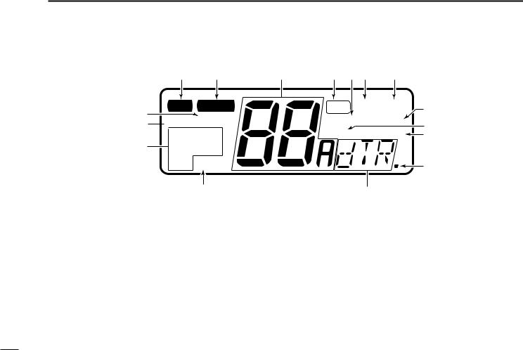
■ Function display
q |
w |
e |
!6
T X BUSY
!5 
 LOW CALL CANUSA
!4 INT WX ALT
!3
q TRANSMIT INDICATOR
Appears while transmitting. (p. 9)
w BUSY INDICATOR
Appears when receiving a signal or when [SQUELCH] is rotated too far counterclockwise. (p. 8)
e CHANNEL INDICATOR
Shows the operating channel. (pgs. 6, 7)
r TAG CHANNEL INDICATOR
Appears when the selected channel is set as a tag channel. (p. 10)
r t y u
TAG DUALTRI |
i |
|
SCAN SCRM |
o |
|
DUP ACK RCV |
||
!0 |
||
|
!2 |
|
!1 |
|
|
t SCAN INDICATOR |
|
Appears and flashes during scan operation. (p. 10)
y DUALWATCH INDICATOR
Appears and flashes during dualwatch operation. (p. 8)
u TRI-WATCH INDICATOR
Appears and flashes during tri-watch operation. (p. 8)
i VOICE SCRAMBLER INDICATOR
Appears while the optional voice scrambler is activated. (p. 8)
4

o DUPLEX INDICATOR
Appears when the selected channel is a duplex channel.
!0ACKNOWLEDGEMENT/RECEIVE INDICATORS
Appear during optional DSC operation. (pgs. 13–18)
•“RCV” appears when a DSC call is received.
•“ACK RCV” appears when an acknowledgement is received.
•“ACK” and “$” appear when transmitting an acknowledgement.
!1DSC INDICATORS (pgs. 13–18)
Appear during optional DSC operation and show a format specifier, message, etc.
!2NMEA INDICATOR
Appears when NMEA devices (such as a GPS receiver) are connected. (p. 12)
!3WEATHER ALERT INDICATOR
Indicates the weather alert function is activated. (p. 7)
!4MODE INDICATORS (p. 7)
•“USA” shows USA channels are selected.
•“CAN” shows Canadian channels are selected.
•“INT” shows International channels are selected.
•“WX” shows weather channels are selected.
PANEL DESCRIPTION 2
!5LOW POWER INDICATOR
Shows that low output power is selected. (p. 9)
!6CALL CHANNEL INDICATOR
Appears when the call channel is selected. (p. 6)
5
 3 BASIC OPERATION
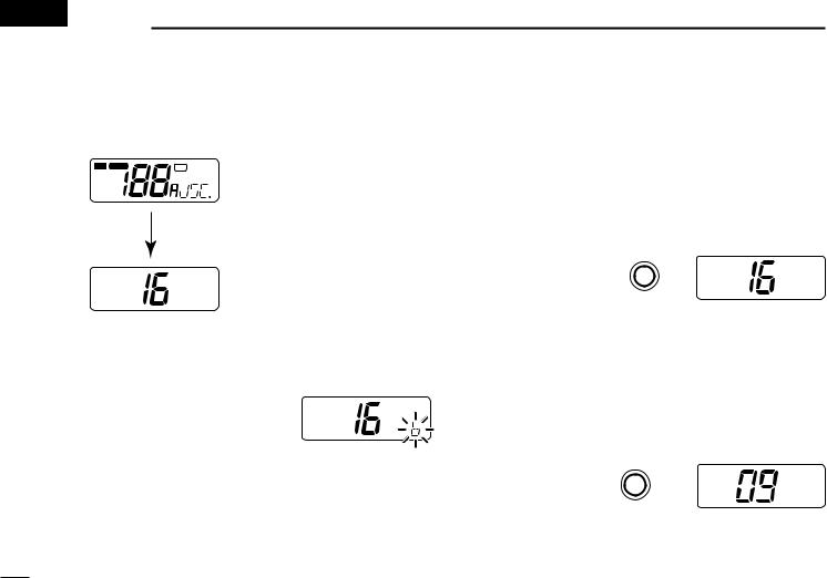
■ Power ON
Rotate [PWR/VOL] clockwise to turn power ON.
T X BUSY |
TAG DUALTRI |
LOW CALL |
SCAN SCRM |
CANUSA |
DUP ACK RCV |
INT |
|
WX ALT |
|
All display indications appear briefly*.
*“SCRM” appears only when an optional UT-79 is installed.
“dSC” appears only when an optional UX-120 is installed.
USA
Operate the transceiver as indicated in the following sections.
D Low voltage indicator
When “b” appears and flashes as
shown at right, there is a DC power USA source problem. In this case, check
your vessel’s battery and DC power cable.
■ Channel selection
D Channel 16
Channel 16 is the distress channel. It is used for establishing initial contact with another station and for emergency communications. Channel 16 is monitored during dualwatch/triwatch. While standing by you are required to monitor channel 16.
Push |
16 |
USA |
or hang the microphone on the microphone hanger.
D Call channel
The call channel is used to store your most often-used channel for quick recall. In addition, the call channel is monitored during tri-watch. The default setting for the call channel is channel 9 which is for pleasure use.
Push |
9 |
CALL |
USA |
“CALL” indicates that the call channel is selected.
6
D U.S.A., Canadian and international channels
There are 61 U.S.A., 57 Canadian and 57 international channels. These channel groups may be specified for the operating area.
Push [CH/WX] to select a regular channel.
•If a weather channel appears, push [CH/WX] again.
Rotate the channel selector to select a channel.
•“DUP” appears for duplex channels.
To change the channel group, push [CH/WX•U/I/C] for 1 sec.
•U.S.A., Canadian and international channels can be selected in sequence.
|
USA |
Push for 1 sec. |
U.S.A. channels |
U / I / C |
|
CH/WX |
|
|
TAG |
DUP |
CAN |
INT |
|
International channels |
Canadian channels |
BASIC OPERATION 3
D Weather channels
There are 10 weather channels. These are used for monitoring NOAA (National Oceanographic and Atmospheric Administration) weather broadcasts.
Push CH/WX
WX
once or twice
CONVENIENT
Weather alert function: NOAA broadcast stations transmit a weather alert tone before an important weather announcement.
When the weather alert function is turned ON, the “ALT” indicator flashes until any key is pushed.
This function is activated when a weather channel is selected or during any scan. See “SET mode items” on p. 19.
7
 Loading...