


(AH-4) (AT-160) (AT-500) (AT-500) (I290) (IC-02) (IC-02) (IC-02) (IC-02) (IC-02) (IC-02) (IC-02) (IC-02) (IC-02) (IC-03) (IC-04) (IC-04) (IC-04) (IC-04) (IC-04) (IC-04) (IC-1200) (IC-1271) (IC-1271) (IC-1275) (IC-1275) (IC-1275) (IC-1275) (IC-1275) (IC-1275) (IC-1275) (IC-1275) (IC-1275) (IC-1275) (IC-1275) (IC-2) (IC-2) (IC-2) (IC-2) (IC-2) (IC-2) (IC-2000) (IC-207) (IC-207) (IC-210) (IC-2100)
Modifications for the ICOM
created 28-03-2002 from www.mods.dk
Icom, AH-4, AH-3 ( automatic antenna tuner ) connection to any radio. English language Using the AT-160 with the IC-706MKII English language
AT-500 Automatic Antenna Tuner Modification English language ICOM AT-500 Tuner Hint English language
Icom I290 scan modification English language
Band expansion modification for IC-02AT English language Audio modification for IC-02 AND IC-04 English language IC-02A Modified PLL rigs English language
Low audio speaker mike on IC2A, 3A, 4A OR 02AT English language ICOM 02/03/04 & Vox Unit English language
Another band expansion mods for Icom IC-02 English language
For increased receive audio and improved response English language To increase the memory scan and search scan speed English language ICOM HS-10SA VOX for IC-02AT Mods English language
ICOM 02/03/04 & Vox Unit English language ICOM 02/03/04 & Vox Unit English language
Out of band modification for IC-04 English language Audio modification for IC-02 AND IC-04 English language
Low audio speaker mike on IC2A, 3A, 4A OR 02AT English language TX delay may be excessive at low temperatures English language IC-04E fuer 9k6 German language
Expanded RF 870 - 960 MHz for ICOM IC-1200 English language VOX of an IC-271,471,1271 usable for FM English language
RAM Card Backup Battery Replacement Instructions English language IC-1275 Freq. steps mod English language
Power control modification English language Restoration of pass band tuning English language Splitting into RXand TX paths English language Modification of cw pass band (BFO) English language Disabling of SBB squelch English language
Very fast AGC English language SSB RF Gain English language Tuning speed English language
Frequency range & CTCSS tones English language
IC 475H / 1275E mod for 9k6 (G3RUH) use English language Modification For IC-2AT English language
Low audio speaker mike on IC2A, 3A, 4A OR 02AT English language ICOM IC-2AT internal antenna connection problem English language ICOM IC-2GAT ext frq for Transmit English language
IC-2AT, If transmit RF indicator notwork properly English language Icom IC-2GXAT open RX English language
Icom IC-2000 Extended RX/TX Mod English language Band expansion for IC-207 English language
Band Expansion for IC-207H English language Schematic of IC-210 English language
Icom IC-2100H Extended Transmit Mod English language
(IC-2100) (IC-211) (IC-22)
(IC-22) (IC-22) (IC-22) (IC-22) (IC-22) (IC-228) (IC-229) (IC-229) (IC-229) (IC-2320) (IC-2330) (IC-2330) (IC-2340) (IC-2340) (IC-2340) (IC-2350) (IC-24)
(IC-24) (IC-24) (IC-24) (IC-24) (IC-24) (IC-24) (IC-24) (IC-24) (IC-240) (IC-2400) (IC-2400) (IC-2410) (IC-2410) (IC-2410) (IC-2410) (IC-2410) (IC-2410) (IC-2500) (IC-2500) (IC-251) (IC-251) (IC-251) (IC-260) (IC-27)
(IC-27) (IC-2700) (IC-2700) (IC-2700) (IC-271) (IC-271)
Expand receiver for IC-2100H EUR version English language IC-211 mod English language
Icom IC22S Packet Modification English language IC-22S mods for 5 KHz step English language
Step modification (packet radio operation) English language Band segment modification English language
Recieve SSB and CW on IC-22S English language
Modifying the IC22A for 9600 baud operation English language IC-228 mods English language
IC-229H, and AM aviation band modification English language IC-229H & 9600 bauds (Anglais) English language
IC-229H Fix CPU/Display board English language Extended RX/TX English language
IC2330A expanded range English language
IC-2330A expanded range (another way) English language IC2340H att modification English language
Some mods for the IC-2340H English language IC-2340 mods English language
IC-2350 expand RX/TX and Crossband rep English language Frequency expansion for IC24 English language Cross-band repeater operation IC-2 English language
Out of band modification of the ICOM IC-24AT English language IC-24AT ext frquency English language
IC-24AT Keyboard command summary English language IC-24AT sensitivity English language
IC-24AT enabling the burst-tone English language IC-24 auf 9600 Baud German language
Tip to to function bottom for IC-24 English language 12,5 Khz mods for IC-240 English language
ICOM 2400A mini repeater function English language IC-2400 144/430 9K6 mod Other language Expansion of receive range English language
800 MHz antenna input English language Cross-band repeat English language
IC-2410 Dual Band External & Mike Remote Codes English language IC-2410 Modification area as follows. New and old version English language IC-2410 TX modification English language
Run 9k6 with an Icom IC-2500 (70cm/23cm TRX) English language Umbau des ICOM IC-2500E auf 9600 Baud German language Modifikcation af IC-251 for 9600 baud English language Modifications for the ICOM IC-251 English language
IC-251 Receive-repair English language IC-260E auf 9600BD German language IC-27 mic-connector mods English language
ICOM IC-27H 2M transceiver for use with the 9k6 English language IC-2700 RX/TX expansion English language
IC-2700 Cross Band Repeater English language
Enabling ICOM 2700H remote operation English language
PSK Transmit Audio Modification for ICOM IC275 & IC271 English language VOX of an IC-271,471,1271 usable for FM English language
(IC-271) (IC-271) (IC-271) (IC-2710) (IC-2710) (IC-275) (IC-275) (IC-275) (IC-275) (IC-275) (IC-275) (IC-275) (IC-275) (IC-275) (IC-275) (IC-275) (IC-275) (IC-275) (IC-275) (IC-275) (IC-275) (IC-275) (IC-275) (IC-275) (IC-28)
(IC-28) (IC-2800) (IC-2800) (IC-2800) (IC-2800) (IC-2800) (IC-2800) (IC-2800) (IC-2800) (IC-2800) (IC-2800) (IC-281) (IC-281) (IC-281) (IC-2AT) (IC-2AT) (IC-2GAT) (IC-2GAT) (IC-2GAT) (IC-2GAT) (IC-2GXAT) (IC-2GXAT) (IC-2IA) (IC-2IA) (IC-2IA)
IC-271 / 471 fuer 9k6 German language
IC-271 sounds raspy in SSB/CW English language
RAM Card Backup Battery Replacement Instructions English language Some modification for IC-2710 English language
Crossband Repeater Operation for the IC-2710 English language
PSK Transmit Audio Modification for ICOM IC275 & IC271 English language IC-275 Freq. steps mod. English language
Band Expand for ICOM IC-275E/H and IC-275A/H English language IC amplifier oscillates English language
Prevent PLL unlock at high ambient temperature English language Improve voice synthesizer and side tone audio English language Prevention of PLL unlock at 174 MHz English language
Improve the stability of the center meter English language
Noise coming from speaker during transmit with audio turned up English language
Eliminate possible spurious emission when thermal switch has turned on during TX English language Frequency range & CTCSS tones English language
Power control modification English language Restoration of pass band tuning English language Modification of cw pass band (BFO) English language Disabling of SBB squelch English language
Very fast AGC English language SSB RF Gain English language Tuning speed English language
Splitting into RXand TX paths English language ICOM IC-28A AND IC-28H ext frq English language
The long, noisy squelch-tail of the Icom IC-28 English language Icom IC-2800h Extended RX Mod English language
Icom IC-2800 Extended RX/TX Mod English language
Icom IC-2800 Extended RX/TX Mod, Australian model English language IC-2800/HM98 tx-audio mod English language
sensitivity ICOM IC-2800H English language IC-2800H cross band mode operation English language DTMF options card English language
Screen saver Turn OFF option for IC-2800 English language Cross Band Repeat for IC-2800 English language
Enable crossband function for IC-2800 English language Crossband repeat English language
Extended Receive for IC-281 English language Extended Transmit for IC-281 English language Coverage IC-2AT 140-150 MHz English language Operation and L3 ADJUSTMENT English language
Out-of-band transmit mod for IC-2GAT handheld 2M transceiver English language Step mods for IC-2GAT English language
IC-2GAT to packet English language
ICOM IC-A20 alkaline headset-adapter lost-in-the-soup English language The ICOM 2GXAT HARDWARE MOD English language
Software mod, to open IC-2GXAT English language IC-2Ia mic mods English language
IC-2IA lousey xmit audio fix English language IC-2IA mod. English language
(IC-2SAT) (IC-2SAT) (IC-2SAT) (IC-2SAT) (IC-2SAT) (IC-2SE)
(IC-2SE) (IC-2SE) (IC-2SRA) (IC-3) (IC-32) (IC-32) (IC-32) (IC-32) (IC-32) (IC-32) (IC-3200) (IC-3200) (IC-3200) (IC-3200) (IC-3200) (IC-3210) (IC-3210) (IC-3220) (IC-3220) (IC-3220) (IC-3230) (IC-3230) (IC-37) (IC-37) (IC-3J) (IC-4) (IC-4) (IC-4) (IC-40) (IC-45) (IC-45) (IC-451) (IC-471) (IC-471) (IC-471) (IC-475) (IC-475) (IC-475) (IC-475) (IC-475) (IC-475) (IC-475) (IC-475) (IC-475)
IC-2SAT out-of-band transmit mod English language Icom IC-2SAT enhancements English language IC-2SA/E Frequency range expantion English language
Icom IC-2SAT unpublished Specificatons English language Software coverage mods, IC-2SAT English language Additional functions of the ICOM IC-2SE English language Extended Icom IC-2SE functions English language
Extending the Rx. coverage of the IC-2SE and IC-4SE English language Extended Receive, Extended TX (136-174 MHZ) English language
Low audio speaker mike on IC2A, 3A, 4A OR 02AT English language Out of band mod for the IC-32AT English language
IC-32E auf 9k6 German language
IC-32AT Elimination of possible faint pulse noise English language Undocumented features of the ICOM IC-32AT English language Cross-band repeater (Icom) English language
Receive coverage for VHF & UHF and enable keyboard entry English language Fix for IC-3200A used on packet English language
IC-3200A TX to RX delay fix English language IC-3200A ext frq 430-440 MHz English language
How To Expand The Coverage Of The Icom 3200A Mobile Radio. English language Frequency Extention RX / TX for ICOM 3200 E English language
IC-3210 prevent signals on TX when the PA modul English language 9K6 with IC-3210 A/E English language
How to iface Ic-3220 & G3RUH English language
ICOM IC-3220A/H Frequency expansion English language ICOM IC-3220A/H mini repeater function English language ICOM IC-3230 Mods for 9k6 English language
IC-3230 repeater function English language some audio mods for IC-37 English language
Now, here is the official Condor Connection IC-37 modification sheet English language Expanded RX for ICOM IC-3J English language
Low audio speaker mike on IC2A, 3A, 4A OR 02AT English language IC-4E Umbau auf 9600Bd German language
IC-4GAT, fix the +5 V source crystal X-3 English language Cloning software for IC-40S English language
IC-45A to IC--45E English language Convertinga IC-45A to IC-45E English language IC-451 aus 9600 German language
VOX of an IC-271,471,1271 usable for FM English language 9600 baud mod for IC-471 English language
RAM Card Backup Battery Replacement Instructions English language IC 475H mod for 9k6 (G3RUH) use English language
Prevent a decrease in RF power output in high ambient temperatures English language IC-475 Freq. steps mod English language
Power control modification English language Restoration of pass band tuning English language Splitting into RXand TX paths English language Modification of cw pass band (BFO) English language Disabling of SBB squelch English language
Very fast AGC English language
(IC-475) (IC-475) (IC-475) (IC-475) (IC-490) (IC-490) (IC-490)
(IC-4SAT) (IC-4SE) (IC-551) (IC-551) (IC-551) (IC-551) (IC-551) (IC-575) (IC-575) (IC-575) (IC-575) (IC-575) (IC-575) (IC-575) (IC-575) (IC-575) (IC-575) (IC-575) (IC-575) (IC-701) (IC-701) (IC-706) (IC-706) (IC-706) (IC-706) (IC-706) (IC-706) (IC-706) (IC-706) (IC-706) (IC-706) (IC-706) (IC-706) (IC-706) (IC-706) (IC-706) (IC-706) (IC-706) (IC-706) (IC-706mkii) (IC-706mkii) (IC-706mkii) (IC-706mkii)
SSB RF Gain English language Tuning speed English language
Frequency range & CTCSS tones English language
Umbau des IC475E/H zum betrieb mit G3RUH-Modem (9600 Baud) German language Modifikation af IC-490 for 9K6 English language
IC-490A 10MHz up modification English language
Anschluss eines G3RUH Modems und AFSK-Modem an IC-490E German language ICOM IC-4SAT extended transmit mod English language
Extending the Rx. coverage of the IC-2SE and IC-4SE English language Modification af the ScanRate and ScanSpeed for IC551D English language IC-551D to rx down to 47.000 MHz English language
IC-551/551D Frequency Alignment English language IC-551/551D EX-107 VOX UNIT -- Installation English language
IC-551/551D EX-108 P.B. TUNE UNIT -- Installation English language IC-575 Freq. steps mod English language
Power control modification English language Restoration of pass band tuning English language Splitting into RXand TX paths English language Modification of cw pass band (BFO) English language Disabling of SBB squelch English language
Very fast AGC English language SSB RF Gain English language Tuning speed English language
Frequency range & CTCSS tones English language General Coverage TX Modification English language Pass band Tuning Modification English language
Extended frequency converage on the ICOM IC-701 HF Transceiver English language Computer control of ICOM 701 via accessory connecter English language
Info/mods for IC-706 English language IC-706 Expanded frequency English language IC706 - spare 0.3A English language
MARS/CAP Modification for ICOM IC-706 English language Icom IC-706 Review English language
Enables out-of-band transmit for 1.6 MHz to 54 MHz English language More semsitive transmit for 2 meter English language
IC-706 60 MHz to 200 MHz bandpass filter English language Icom IC-706 Extended RX mod English language
Some tips. German language
IC-706, MKII, MKIIG xmit mods - tip English language
IC-706 10 watt tune modification/An Icom IC706 Tune Trigger English language "Halbautomatik" für manuelle Tuner am ICOM IC-706 German language
FM Transmit Fix English language
IC-706 Microphone Audio Response Improvement English language Improved VHF recieve mod (see also yellow wire mod) English language To expand the band on the VHF portion English language
Adding an extra RX-only port in the Icom IC706 English language ICOM 706 MKII Extended transmit mod English language
Special on IC706mkII English language
TX range expansion for IC-706MKIIG English language Expand only mod for the IC-706MkII English language
(IC-706mkii) (IC-706MKII) (IC-706MKII) (IC-707)
(IC-718) (IC-718) (IC-720) (IC-720) (IC-720) (IC-725) (IC-725) (IC-728) (IC-729) (IC-729) (IC-730) (IC-735) (IC-735) (IC-735) (IC-735) (IC-736) (IC-736) (IC-737) (IC-737) (IC-738) (IC-740) (IC-745) (IC-745) (IC-745) (IC-746) (IC-746) (IC-746) (IC-746) (IC-746) (IC-746) (IC-746) (IC-746)
(ic-746pro) (IC-751) (IC-751) (IC-751) (IC-751) (IC-751) (IC-751) (IC-751) (IC-751) (IC-756) (IC-756) (IC-756) (IC-756) (IC-756)
mods IC706 MKIIG por EA1DOU (ver. Española) Other language Modifikation IC-706MKIIG für 9k6 PR und Pactor German language IC-706MKIIG mod English language
Receive and Transmit Expansion for ICOM IC-707 English language IC-718 TX 1.8 - 30 MHz English language
Modify IC-718#04 to IC-718#03 English language ICOM IC-720 extended xmit English language
Modifying IC-720A to get rid of rotary relay English language Amtor mods FOR IC-720A English language
ICOM IC-725 MARS modifications English language ICOM IC-725a post 1998 Version. English language
Modification Icom IC-728: General coverage TX English language Using two Icom rigs in transceive English language
Modification Icom IC-729: General coverage TX English language Preventative Maintenance for the ICOM IC-730 English language Xmit Mods for IC-735 English language
TX Mod For ICOM 735 English language IC-735 Remote Working English language
ICOM Radio/RS232 interface which meets RS232 specifications English language Speed-up the ALC for IC-736 English language
Icom IC-736 DDS/VCO Bug/Fix English language
Icom IC-737 general coverange in transmission English language CW Filter Switching Modification for the Icom 737 English language Extended TX modification for Icom IC-738 English language Display/distortion problems ICOM IC-740 HF rig English language IC-745 - PROBLEM: Tuning counts slowly down English language ICOM IC-745 Unlocked English language
RAM Card Backup Battery Replacement Instructions English language IC-746 out of range TX/RX English language
IC-746 Modification English language Extended RX/TX for IC-746 English language
Separating the Tx and Rx lines English language Power mod for the IC-746 English language Solutions for chip blowing with mPC English language Monitor Audio Output Too Low English language Schematic for ICOM CI-V Option English language
TX modification for IC-746PRO (version #02 USA) English language Allow CW Xmit & USB recieve split mode for IC-751 English language IC-751 to 37 MHz English language
IC-751 Bad Cap Problems English language
General coverage mod for the ICOM IC-751A English language IC-751 Switch Matrix English language
How to replace the lithium battery in your ICOM radio English language RAM Card Backup Battery Replacement Instructions English language ICOM IC-751 Dual RAM back-up Battery Modification English language IC-756 Expand TX Frequency English language
Spectrum Scope Adjustments English language ACC1 Audio Output Increase English language
General Coverage H.F. TX Mod (1.6 - 30.0MHz) English language IC-756 wide band modulation English language
(IC-756pro) Expand tx-freqeuncy for the IC756-PRO English language (IC-756PRO) ICOM IC-756PRO CW Filter Shape Selection English language (IC-756pro2) IC-756PRO2 TX mods 100 Khz - 60 MHz English language (IC-756PRO2) TX expand on IC 756PROII #23 EU models English language (IC-761) Wider SSB band on the IC-761 English language
(IC-761) IC-761 activate tuner when in general coverage mod English language (IC-761) IC-761 Out of band English language
(IC-765) Icom IC-765 improved monitor volume English language (IC-765) Icom IC-765 Passband tuning mod English language (IC-765) Mod to prevent ant sw unit failure English language (IC-765) Adjustment the mortrs control unit English language (IC-765) IC-765 Extended TX Mod English language
(IC-765) Replace 455 SSB filter w fl 44a very nice selectivity. English language (IC-775) New product information IC-775DSP English language
(IC-775) IC-775DSP Out of Band Information English language
(IC-775) Increase the sensitivity on MW-band 0.5-1.6MHz on IC-775 and IC-775DSP English language (IC-781) IC-781 General coverage transmit mod English language
(IC-781) 781 ALC Circuit problem English language
(IC-781) Reduce the internal heat by the speaker English language (IC-781) Icom IC-781 filter modification English language (IC-820) IC-820 Test results G3RUH English language
(IC-820) 1750Hz on IC-820, modif English language
(IC-820) ICOM IC-820H extended receive/transmit modification English language (IC-820) ICOM IC-820H cross band repeat modification English language (IC-820) IC-820H display board English language
(IC-821) IC-821H mods for extended TX/RX coverage: English language (IC-821) ICOM IC-821H - Frequenzerweiterung: German language (IC-821) ICOM IC-821H X-Band mod English language
(IC-821) Icom IC-821H mods English language
(IC-900) ICOM IC-900 Out of Band Modifications English language
(IC-900) IC-900 Memory Expansion Modification (Preliminary Rev II) English language (IC-901) IC-901A Frequency Ranges English language
(IC-901) Memory and microprocessor reset English language (IC-901) Crossband repeat English language
(IC-910) Expanded functions for the IC-910H (All versions) English language (IC-910) IC-910H mods English language
(IC-970) IC-970 with 9600 Baud English language
(IC-DELTA1) Band expansion modification for IC-Delta1A English language (IC-DELTA1) IC-Delta 1E repeater mode English language
(IC-F3/4) Icom F3/4 extended RX & TX English language
(IC-M100) Icom IC-M56, M58, M59, M100 - M125 Additional frq. range English language (IC-M11) Icom IC-M11 Additional frequencies and range English language
(IC-M125) Icom IC-M56, M58, M59, M100 - M125 Additional frq. range English language (IC-M56) Icom IC-M56, M58, M59, M100 - M125 Additional frq. range English language (IC-M58) IC-M58 cloning program English language
(IC-M58) Icom IC-M56, M58, M59, M100 - M125 Additional frq. range English language (IC-M59) Icom IC-M56, M58, M59, M100 - M125 Additional frq. range English language (IC-M700) ICOM M-700 Marine Transceiver English language
(IC-M710) Cloning program for IC-M710 English language (IC-MU2) IC-MU2 Ext Band mods English language
(IC-P2AT)
(IC-P2ET)
(IC-P3AT) (IC-PCR1000) (IC-PCR1000) (IC-Q7) (IC-Q7) (IC-Q7) (IC-Q7) (IC-Q7) (IC-Q7) (IC-Q7) (IC-Q7) (IC-R10) (IC-R10) (IC-R10) (IC-R3) (IC-R71) (IC-R71) (IC-RP3010) (IC-T2) (IC-T2) (IC-T22) (IC-T22) (IC-T3H) (IC-T7A) (IC-T7H) (IC-T7H) (IC-T8) (IC-T8) (IC-T8) (IC-T8) (IC-T8) (IC-T8) (IC-T81) (IC-T81) (IC-T81) (IC-U16) (IC-U2AT) (IC-V8) (IC-V8000) (IC-W21) (IC-W21) (IC-W21) (IC-W21) (IC-W2A) (IC-W2A) (IC-W2A) (IC-W2A) (IC-W2A)
ICOM P2AT keyboard mods English language Sensitivity for the Icom IC-P2ET English language
RX and TX modifications for ICOM P3AT English language Icom IC-PCR1000 frequency modification English language ICOM PCR1000 Software English language
IC-Q7 Erfahrungen German language
Extending fq-tx coverage on IC-Q7E English language Icom Q7A mods from the factory English language Modifying the ICOM IC-Q7A for RX/TX English language
Expand transmit from 136-174 and 400-470 for IC-Q7E. (Australian version) English language
IC-Q7 Programming utility 1.05 ( Goran Vlaski ), Wide RX 0-30MHz, Adjustment mode English language IC-Q7A Full Transmit From 140 - 174 MHz and 400 - 470 MHz English language
9k6 with ICOM IC-Q7E German language
IC-R10 Instruction Manual QUICK REFERENCE by PY3PSI English language ICOM R10 Receiver Modification to Provide S-Meter Output English language IC-R10 descriminator output modification English language
IC-R3 to receive SSB from DC to 2.450GHz including the AO-40 satellite English language RAM Card Backup Battery Replacement Instructions English language
RAM board programming interface & R71A modification English language IC-RP3010 disable the CTCSS English language
Expand TX/RX frequency English language IC-T2H Receive 100-200 MHz English language
To expand receive from 136-174MHz FM to 136-174/270-410MHz FM: English language Extended transmit for IC-T22 English language
Extended RX/TX English language Icom IC-T7A Mods English language Expand frequncy English language
Disassembly instructions for IC-T7H English language IC-T8 AM/FM/Wfm function English language Software mods to open the RX-band English language Problem with the battery pack English language
TX Mod for the IC-T8a English language
Sensitivity for the IC-T8E after freq modification English language Cellular mod English language
IC-T81 AM/FM/Wfm function English language IC-T81 Frequency Expansion English language ICOM IC-T81A Cellular Mod English language How to program the ICOM-U16 English language
Extended TX mod for the Icom IC-u2AT English language
IC-V8 MOD for expanded RX/TX range. (136 – 174MHz) English language v8000 gne caper English language
Receive only expansion for IC-W21 English language Transmit expansion for IC-W21 English language Full cross band repeater operation English language
Band expansion 50-999 MHz for IC-W21 English language IC-W2A Expand frequency English language
IC-W2A Cross Band Repeat Function English language IC-W2A Extended Transmit Mod English language IC-W2A signal level English language
IC-W2A Weak transmit audio English language
(IC-W2E) (IC-W31) (IC-W31) (IC-W31) (IC-W31) (IC-W31) (IC-W31) (IC-W32) (IC-W32) (IC-W32) (IC-W32) (IC-W32) (IC-W32) (IC-X2A) (IC-Z1A) (IC-Z1A) (IC-Z1A) (MISC)
(MISC)
(MISC)
(MISC)
(MISC)
(MISC)
(MISC)
(PS85) (R-1) (R-7000) (R-7000) (R-7000) (R-7000) (R-7000) (R-7000) (R-7000) (R-7000) (R-7000) (R-7000) (R-7000) (R-7000) (R-7000) (R-7000) (R-7000) (R-7000) (R-71) (R-71) (R-71) (R-71) (R-7100) (R-7100) (R-8500) (SM-20)
IC-W2E Expand frequency English language
IC-W31E Frequenzbereichs-Erweiterung German language IC-W31E CROSS-BAND-REPEATER German language IC-W31 RX Mod English language
RX/TX expand for ICOM IC-W31E English language IC-W31 RX mod part 2. English language
Cross Band Repeating with the Icom IC-W31A English language
Expanded Frequency Coverage on TX/RX for the Icom IC-W32A/E English language Crossband repeater and extended RX/TX mods English language
To extend the receiver and open up 800 MHz receive (cellular blocked) for IC-W32A English language IC-W32 TX modification. Only a picture. English language
ICW32 E Crossband repeater German language Icom IC-W32A programming glitch English language
Cross Band Repeat Function for the ICOM IC-X2A English language IC-Z1A Extended Receive English language
IC-Z1A 800-900 MHz Receive English language
Pictures for the two modification above English language
ICxx71 ram adaptor for use with eprom programmer English language BNC connectors for ICOM HTs replacement English language
CAT interface for any ICOM English language Reset ICOM radios English language
Use ICOM SM-20 Mic to Yaesu ,Kenwood, etc. English language Icom Hex Addresses English language
QRP mod for ICOM transceivers English language ICOM PS85 fan modification English language R1 (and IC-nSAT) Owners Note English language
Examining the icom ic-r7000 receiver English language
Cool your R-7000 receiver with another heat sink English language Add a cooling fan to your R-7000 receiver English language
TV interface for R-7000 English language
198 channels for your R-7000 English language
Modify your ICOM R7000 to scan and search faster English language A low cost panadaptor for the R-7000 English language
The frequency displayed and actually received are not the same English language The S-meter may not drop to 0 when recieve 500-800 MHz English language Increase the number of memory channels to 200 English language
The remote relay sometimes stays energized English language To improve audio quality in SSB operation English language If display fails to operate at power on English language R-7000 Display/Sensitivity Problem English language IC-R7000 scanning improvement English language Intermittent display English language
Tricking the ICOM R-71A to tune below 100 KHz English language Modifications to the Icom R71A IF filter selection circuit English language
Here is the R-71 version of the Drake R7/R8 type passband tuning system English language R-71A Memory Notes English language
Modify your Icom R7100 to provide an output directly from the discriminator English language Icom R7100 Discriminator Mod English language
Operating the Icom R8500 in other contries English language Icom SM-20 desktop microphone wiring English language
31-01-2000
(AH-4) Icom, AH-4, AH-3 ( automatic antenna tuner ) connection to any radio.
Author: AA7OL Niko Takahashi - aa7ol@hotmail.com.MODIFICATION.NET
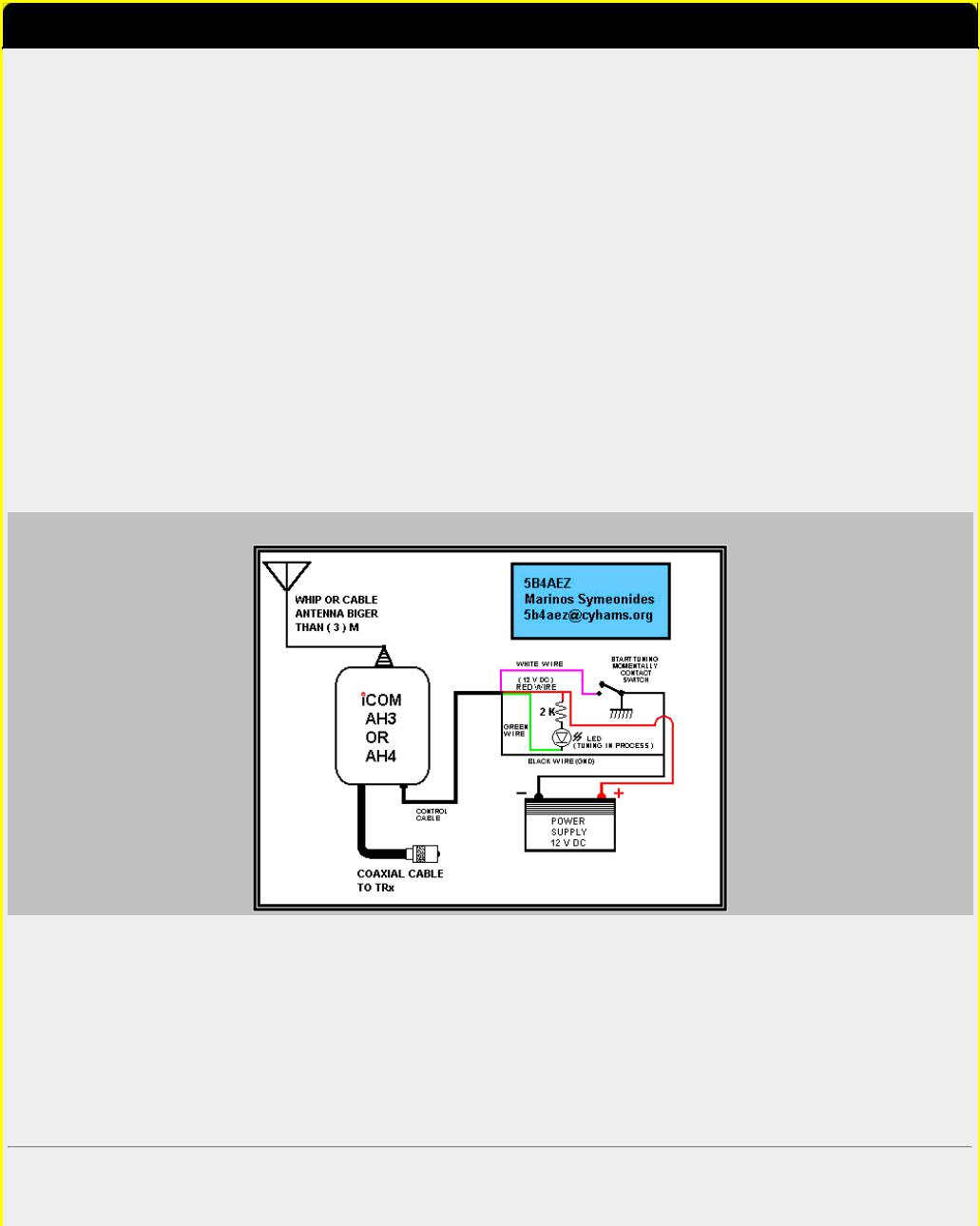
Icom AH-4 and AH-3 ( automatic antenna tuner ) connection to any radio
Both AH-3 and AH-4 are similar 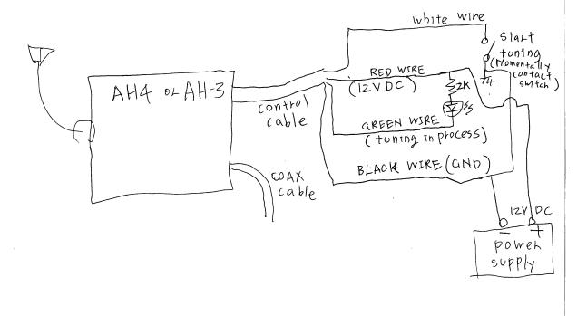 Here is a redesign of connection digram of the ICOM IC-AH3 and IC-AH4 by 5B4AEZ.
There is four wire control cable coming out beside coax cable.
Control cable has
White: Start tuning
Green: Tuning in process
RED: 12 V DC input
Black: GND
Tuning Process
1. Put about 10 watts of power into tuner. ( CW )
2.After about 0.5 second, press start switch for a moment. ( use momentary contact switch )
3.LED start blinking , which indicate tuning is in process.
4.After about 3 seconds or so, LED shut off, and tuning is completed,
If tuning is successful SWR should be less than 1.2
Some radio start to reduce the power when SWR is high, this tuner takes at least 10 watts of power for tuner to work properly. Most of the 100 watts radio should not have any problem, since they still put out 10 watts or so, even with high SWR.
But, it does not work with some QRP radio ( 5 watts or less ).
Adjust power level, if necessary.
You may extend control cable to 100 feet , it still work fine, you can put this tuner on top of tower.
Let me know , how it worked
aa7ol@hotmail.com.MODIFICATION.NET
This modification is read 1503 times. |
top of page |
07-06-2001
(AT-160) Using the AT-160 with the IC-706MKII
Author: Dave Abshire Sr. - KG4KOX - KG4KOX@aol.com.MODIFICATION.NET
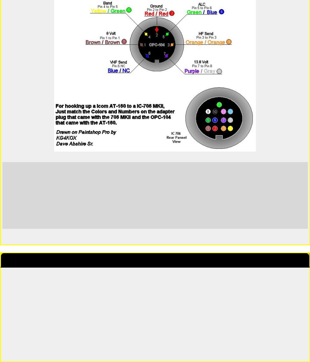
ICOM's IC-706MKII transceiver and AT-180 antenna tuner are designed to work together. However, ICOM's AT-160 is a very popular antenna tuner. Originally designed to work with the IC-728 and IC-729 transceivers (now out of production), the AT-160 will work with the IC-706MKII if the following instructions are followed:
1.(IC-706MKII only, not IC-706) The IC-706MKII will transmit on VHF constantly when connected to the AT-160. To stop this, remove the wire attached to pin 6 of the DIN connector within the OPC-104 cable.
2.Open the AT-160 and make sure the switch labelled "S1" on the circuit board is switched to the bottom, shown as "IC725/726" in the AT-160 instructions.
3.Make sure that the connections to the AT-160, using the OPC-319, OPC-104, or OPC-125C cables, are according to the AT160 instruction manual. ICOM America suggests using the OPC-599 adapter cable for connection of the OPC-104 to the IC706MKII.
4.Connect the radio to the transmitter terminal and connect an antenna to the ANT terminal. Make sure the antenna has less than a 3:1 SWR. Place the radio in FM, AM or RTTY mode and key the mic. The AT-160 will now tune properly.
5.The tuning button on the front of the IC-706MKII will not operate when using the AT-160 antenna tuner. This feature was designed to work with the AT-180.
6.Check the SWR presented to the radio. It should be less than 1.5:1. The AT-160 operates with the IC-706MKII as it would with the IC-725 or 726 transceivers. Included with the AT-160 instructions is a page dedicated to the antenna tuner's operation with an IC-725 and IC-726 transceiver. This is not the way the AT-160 operates with the IC-706MKII.
7.There is no way to turn the AT-160 off or place it into "thru" mode when operating with the IC-706MKII.
Date: 18-06-2001 |
User comment |
From: Dave KG4KOX |
Subject: Extra note |
|
|
|
|
|
|
|
|
I cut one end off the OPC-104 that came with the AT-160 and used the small 13 pin adaptor that came with the 706 MKII. NOW you must leave pin 6 un-connected or your radio will stay keyed on 2 meters.
I did the mod and it works great on HF but I can't get it to tune proper on 6 meters, It will tune to a 1:1 then next time you key up it will retune again. If anyone knows a way around this please let me know.
Dave
KG4KOX
This modification is read 711 times.
top of page
19-07-1998
(AT-500) AT-500 Automatic Antenna Tuner Modification
I have been using the icom at-500 automatic antenna tuner for six months, and it is a great piece of gear. however, there is a very minor modification i performed to the tuner to better suit my needs.
The tuner automatiacally selects one of four antenna s0-239 connectors on the back depending upon which band you are operating. Many of us utilize one feed line for an 80 and 40 meter dipole or inverted vee. The at-500 (and at-100) has two seperate antenna terminals for these bands. If you desire to use one feed line for both of these lower band antennas, you either have to install a coax switch and manually switch the tuner in line, or unscrew the pl-259 connector from one antenna terminal and install it on the other. All of this is inconvenient and defeats the purpose of an automatic tuner.
The mod i performed is extremely simple. I moved the wire going to antenna terminal #3 and moved it to terminal #2. This directs the 80 meter rf to the same terminal as the rf for 40 meters and allows one to use the same antenna terminal for both bands and one feed line. To perform the change, remove the top cover of the tuner, locate the two correct terminals using page 6 of the manual, unsolder the one to be move, and solder it to the correct terminal. The terminals are easy to reach.
Just be sure all connections are good.
This modification is read 912 times.
top of page

21-10-1999
(AT-500) ICOM AT-500 Tuner Hint
Author: Dave Parlier - dcparlier.nj@worldnet.att.net.MODIFICATION.NET
10/12/99
The IC AT-500 Auto Tuner has four (4) antenna coax plugs on the rear for various bands.
You can solder all band wires needed to a single terminal lug and use only one (1) coax connector, if desired (per ICOM user manual). If you prefer not to "go inside" , then two short coax pieces fed into a "T" coax connector will feed two separate frequency ranges (e.g. 80m & 40M) into a single connection point.
Dave Parlier W2CGG
Chatham, NJ
This modification is read 822 times.
top of page
19-07-1998
(I290) Icom I290 scan modification
The objective of the modification is to implement a delay before scanning restarts when, in SCAN-STOP mode on BUSY frequency, the received signal disappears.
The modification will then allow a frequency to be free for a while before scanning resumes.
With this modification, it will be given a chance to a signal to come back within a few seconds before the scanning restarts. Now multiple QSOs or poor signals won't be truncated any more because of a too much impatient scanning !
WHAT TO DO:
Very simple. On the SENSOR UNIT, just solder a jumper between:
●the unused contact of switch S3 (the one corresponding to the TIMER OFF position of the circuit commanding the SEL pin of IC1)
●and the EMPTY signal of connector J3 (this is the extreme pin nearest S2 on the SENSOR unit)
ATTENTION, there are some errors on the electrical scheme that I possess reference A-0488 :
●The S3 switch is represented in position TIMER OFF and not ON as written. You have to reverse labels OFF and ON.
●The signals BUSY and EMPTY on connected are reversed. EMPTY (SQ1) is on the extreme left pin of S3 and BUSY is on 2nd pin of this connector S3. In fact, the switch S2 is drawn in the BUSY position and not EMPTY.
HOW IT WORKS :
The TIMER starts when pin SEL of IC1 goes to 0V. When the TIMER is running, the scanning is halted. The scanning also stops when the BUSY signal is low level (0V) on pin SQL of IC1.
Let us suppose that a signal is received. Then BUSY goes to 0V and scanning halts. At the same time the EMPTY signal , which is the inverse of BUSY, goes to 5V and the TIMER remains off.
If the received signal disappears BUSY goes high and EMPTY low, then the TIMER is enabled and starts running. It also maintains the scanning in halt mode.
If, at the end of the TIMER delay, no signal has come back then the scanning restarts.
If a signal comes back before the end of the TIMER delay then the BUSY signal returns to 0V and maintains the scanning in halt mode. In the meantime the TIMER will run until the end of its delay without any action on the process.
The TIMER delay is chosen with the R32 potentiometer on the SENSOR UNIT. The minimum value is about 4 to 5 seconds which is perfect for this working mode.
Small modification .... great effect !
Gabriel F6DQM @ FF6PTT.FRPA.FRA.EU
This modification is read 407 times. top of page

19-07-1998
(IC-02) Band expansion modification for IC-02AT
FOR SERIAL NUMBERS ABOVE 34000
BY LTC STEVE PETERS, CAP
1.Remove back from radio (5 screws) and bottom plate (4 screws).
2.Carefully remove radio chassis from front case by pulling out top of radio and lifting slightly (to remove battery contacts from bottom case). Be extremely careful of ribbon cable and heat sink compound on power amplifier module.
3.Remove diode D2 from matrix board.
4.Add diode D4 (any small diode 1N4148; 1SS211
5.The following is a schematic of the matrix board:
ADD |
D4 |
|
REMOVE D2 |
|
|
I--+ |
|
--+-- |
--+-- |
+ |
|
V D4 |
|
ID3 I |
ID2 |
I |
D1 |
I |
|
I I |
I |
I |
|
+ |
+ |
+---+ |
+---+ |
+ + |
|
6.Install radio chassis back into front cover. Leave back off temporarily.
7.Carefully apply power to radio and enter the lowest desired frequency.
8.Adjust slug through bottom hole on VCO corr for .5 VDC at VCO test point (just below VCO shield) at lowest desired operating frequency.
9.This completes the modification. A few words of caution: 1. The radio is not type accepted for use in the commercial band. 2. Make sure you reinstall the battery latch correctly on bottom of radio or battery will become permanently locked onto radio. 3. Tighten screws on bottom of radio snuggly. If they loosen while battery is connected you cannot remove the battery. (This has happened to any units and it would be prudent to periodically check these screws to assure their tightness.)
This modification is read 1612 times.
top of page
19-07-1998
(IC-02) Audio modification for IC-02 AND IC-04
This audio mod works on the 02 and 04AT. It increases the level of audio, as well as rolling off some of the lows. Sounds real nice. It involves the circuit around Q105.
1.Replace C119 with a .01 uF cap (disc ceramic is fine).
2.Parallel R131 with a 1 uF cap (use a tantalum cap).
3.Parallel R132 with a .01 uF cap (disc ceramic is fine).
This is not the same mod as the one International Radio is advertising, which involves changing C117.
I tried an AB-1 Audiolaster from Engineering Consulting, and was very unhappy with the results. I am very pleased with the audio given by this mod (much cheaper too!).
This modification is read 1146 times.
top of page
19-07-1998
(IC-02) IC-02A Modified PLL rigs
The modification to the IC-02A to increase the receiver is fairly straight forward although a little delicate. The programming diodes are located on the board directly behind the front panel, and are located in the corner of the board. They are little rectangular black three leaded devices.
The proceedure to modify the radio is as follows:
1.Remove diode D2 - use a very small iron and solder wick to remove most of the solder, then lift the diode GENTLY while heating the single tab side. After getting the first tab free, proceed to the other two tabs, lifting them one at a time. Do NOT use a large iron or too much heat.
2.Take the diode and locate in the position labled D5. Carefully solder the diode in place.
3.Reassemble the radio except for the back.

4.Program the radio to the local weather channel (162.400 or 162.550) in the following manner: 6 2 4 0 0 or 6 2 5 5 0
NOTE:
the programming proceedure now requires that you enter the ten's of Mhz when entering a frequency.
5.Look at the back of the radio. In approximately the center of the exposed board is a metal can with two adjustments. The top adjustment is a metal screw (actually a trimmer capacitor) while the bottom adjustment is a black slug with a small rectangular adjusting slot
6.With the squelch open, adjust the lower black core counterclockwise approximately 1 1/4 turns until you receive the weather station. As soon as you receive the weather, STOP turning the adjustment.
7.Replace the back on the radio and you are in business.
With this modification, the radio will tune from 140.000 Mhz to something over 162.550 without difficulty. Just remember that you must enter the ten's of Mhz when entering a frequency. This modification does not affect the transmitter which still covers 140.000 to 151.995 Mhz.
Please note: This mod does not retune any of the RF stages of the receiver so the sensitivity is down some at the weather frequency, however, I have no difficulty receiving it at thirty to forty miles.
I do have the ICOM service manual on the IC-02A. I purchased it from Delaware Amateur Supply at a local hamfest several weeks ago.
According to the manual, the VCO on the PLL should cover 25 Mhz. minimum.
This modification is read 1203 times.
top of page
19-07-1998
(IC-02) Low audio speaker mike on IC2A, 3A, 4A OR 02AT
If you own one of the IC2A, 3A, or O2AT series Hand-helds, you may be interested in reading on. I know my hearing is pretty good, but have you ever tried to listen to the audio coming out of your speaker mike on the above ICOM's? For the most part, it's pretty low. I may be the last guy to figure out a cure for this, but here it is anyway. On the O2AT, etc., there is a groove on the back near the top of the rig that is just the right size to accept the HM9 speaker mike turned 90 degrees so that the mike plug fits in that groove in the rear of the rig. Thus alllowing all the audio to be heard from the internal speaker of the rig, usually much better than the speaker mike.
Now, in the case of the 2A series, etc., the fix is more complex. These rigs don't have that handy groove built in, so I decided a groove had to be made to accept this configuration. I thought long and hard about a minute, before getting the "Dremel" out and making my own slot or groove. It works well on both hand-helds I have. In fact, you can hook up an external speaker for even more loudness in the auto. So, give it a try or see me for a demo.
This modification is read 1034 times.
top of page
19-07-1998
(IC-02) ICOM 02/03/04 & Vox Unit
The ICOM Family of Hand-Held Radios (02/03/04 AT) are well suited for packet radio given the many available power supply options.
The big problem is getting the PTT to operate " CLEANLY " while not compromising the audio level from the TNC when using the resistor or resistor/capacitor interfaces suggested in some manuals.
I am using the ICOM HS10-SA Vox unit to interface the ICOM 02/04 AT here.It has worked somewhat well for some time but I was always plagued with a MINIMUM 200 msec transmit "hang " delay until I tore it apart for examination and correction.
The small " delay " pot on the front of the unit is in series with a 2.2 Megohm resistor (R-19 on the board). The adjustable pot is also about 2 megohms as well. This combination allows a MINIMUM VOX "hang" transmit delay of 200 msec.
By identifiying the solder connections for R-19 on the back of the PC board and placing a low value resistor ( or jumper ) in parallel....I was able to achieve a ZERO "hang" transmit delay time with the delay pot in the FULL COUNTER-CLOCKWISE position. The minimum 200 msec delay has been defeated.
This modification is read 1050 times.
top of page

19-07-1998
(IC-02) Another band expansion mods for Icom IC-02
The following method of modifying the Icom IC02 is an alternate to the IC02.MOD file. This one should give you PL out of band without jumpering 5 VDC to the tone chip. Use 1N914 or equivelent when adding diodes.
1.On the logic matrix, remove D402 and D403.
2.Add D402, D403 and D404 with the cathode at 4 o'clock and the anode at 12 o'clock.
3.Retune the VCO to cover your desired frequency spread. My 02AT did not want to go beyond 163 MHz. I have a friend whowas able to get his to the low 170s.
4.To jump from 140 to 150 or from 150 to 160 (or vice versa) you must "tune across" the boundry, in the same way that you do for an unmodified 02AT. For example, key in 149.995 and then move up until you are in the 150s. You can then enter any 150 MHz frequency (starting with the MHz).
This modification is read 1387 times.
top of page
19-07-1998
(IC-02) For increased receive audio and improved response
Solution: Remove C117. C117 is a .22 uf capacitor. It can be located by first finding the 8 pin IC that is neart the middle of the "Main Unit". Looking immediately above it (above pin 4) untill you see 2 round polarized capacitors. The one on the left is C117. It can be successfully removed by just bending it back and forth untill the leads break. Be carefull to get the right one!
This modification is read 1051 times.
top of page
19-07-1998
(IC-02) To increase the memory scan and search scan speed
Solution: Install a 100k ohm resistor across R413. To locate R413 Remove the DTMF Board that is attatched to the inside front of the radio by removeing the two small screws. You will now have the logic unit exposed. IC401 (which is the postage stamp sized IC near the middle of the board) is easily visible. Locate the bottom right corner of this device and continue down until you come to the first micro chip resistor. This is R413. Carefully install a 1/8 Watt or smaller 100K ohm resist or across it.
This dramatically increases the scan speed but also raises the "BEEP" tone frequency.
This modification is read 1082 times. |
top of page |
19-07-1998
(IC-02) ICOM HS-10SA VOX for IC-02AT Mods
The ICOM headset VOX model HS-10SA for the IC-O2AT can be a handy unit for mobile use but it has a serious limitation as it comes from the box. There is no way to turn it off other than unplugging it! This means any conversation with a passenger, cough or sneeze goes out over the air.
Fortunately there is any easy remedy. Remove the 3 screws holding on the rear cover and the single screw holding the circuit board. Carefully lift out the board and locate R23. It is a 4.7K 1/8 W resistor located near the lower edge of the board.
One end of it connects to the white lead of the cable to the HT. The other end connects to the collector of Q7. This is the keying circuit. In normal operation, Q7 is saturated when the VOX is active. Since the emitter of Q7 is grounded, R23 is effectively connected from the white lead to ground, keying the HT. Carefully unsolder the end of R23 which goes to Q7 and lift this lead out.
Drill a 1/4 inch hole in the center of the end of the case and mount a SPDT switch. The switch the author used was a C & K 7207 which is a 3 position, center off, SPDT, with one side spring return momentary and the other side latching. This allows the momentary side to be used to key the HT manually, the latching side for the VOX operation, and the center OFF.
Now connect the center pole of the switch to the end of R23 which used to go to Q7. Connect the latching side of the switch to the hole in the board where R23 was (Q7) and the momentary side of the switch to ground (shield of cable to HT). Now reassemble the unit and test.
This modification is read 1015 times.
top of page

19-07-1998
(IC-03) ICOM 02/03/04 & Vox Unit
The ICOM Family of Hand-Held Radios (02/03/04 AT) are well suited for packet radio given the many available power supply options.
The big problem is getting the PTT to operate " CLEANLY " while not compromising the audio level from the TNC when using the resistor or resistor/capacitor interfaces suggested in some manuals.
I am using the ICOM HS10-SA Vox unit to interface the ICOM 02/04 AT here.It has worked somewhat well for some time but I was always plagued with a MINIMUM 200 msec transmit "hang " delay until I tore it apart for examination and correction.
The small " delay " pot on the front of the unit is in series with a 2.2 Megohm resistor (R-19 on the board). The adjustable pot is also about 2 megohms as well. This combination allows a MINIMUM VOX "hang" transmit delay of 200 msec.
By identifiying the solder connections for R-19 on the back of the PC board and placing a low value resistor ( or jumper ) in parallel....I was able to achieve a ZERO "hang" transmit delay time with the delay pot in the FULL COUNTER-CLOCKWISE position. The minimum 200 msec delay has been defeated.
This modification is read 462 times.
top of page
19-07-1998
(IC-04) ICOM 02/03/04 & Vox Unit
The ICOM Family of Hand-Held Radios (02/03/04 AT) are well suited for packet radio given the many available power supply options.
The big problem is getting the PTT to operate " CLEANLY " while not compromising the audio level from the TNC when using the resistor or resistor/capacitor interfaces suggested in some manuals.
I am using the ICOM HS10-SA Vox unit to interface the ICOM 02/04 AT here.It has worked somewhat well for some time but I was always plagued with a MINIMUM 200 msec transmit "hang " delay until I tore it apart for examination and correction.
The small " delay " pot on the front of the unit is in series with a 2.2 Megohm resistor (R-19 on the board). The adjustable pot is also about 2 megohms as well. This combination allows a MINIMUM VOX "hang" transmit delay of 200 msec.
By identifiying the solder connections for R-19 on the back of the PC board and placing a low value resistor ( or jumper ) in parallel....I was able to achieve a ZERO "hang" transmit delay time with the delay pot in the FULL COUNTER-CLOCKWISE position. The minimum 200 msec delay has been defeated.
This modification is read 588 times.
top of page
19-07-1998
(IC-04) Out of band modification for IC-04
1.On the logic matrix, remove D402.
2.Add D402, D403 and D404 with the cathode at 4 o'clock and the anode at 12 o'clock. (You may use any signal diode such as 1N914)
3.Add D405 with the cathode at 8 o'clock and the anode at 12 o'clock.
4.If you have a newer 04AT, the VCO cover will have holes in it that allow access to the tuning coils. If you have an older 04AT you will have to cut a hole in the VCO cover using a pair of small diagonals (be careful!).
5.Retune the VCO to cover your desired frequency spread. My 04AT goes from 441 to 473 MHz, which is pretty good.
6.Any frequency may be entered directly on the keypad (starting with the 10 MHz digit).
This modification is read 673 times.
top of page

19-07-1998
(IC-04) Audio modification for IC-02 AND IC-04
This audio mod works on the 02 and 04AT. It increases the level of audio, as well as rolling off some of the lows. Sounds real nice. It involves the circuit around Q105.
1.Replace C119 with a .01 uF cap (disc ceramic is fine).
2.Parallel R131 with a 1 uF cap (use a tantalum cap).
3.Parallel R132 with a .01 uF cap (disc ceramic is fine).
This is not the same mod as the one International Radio is advertising, which involves changing C117.
I tried an AB-1 Audiolaster from Engineering Consulting, and was very unhappy with the results. I am very pleased with the audio given by this mod (much cheaper too!).
This modification is read 564 times.
top of page
19-07-1998
(IC-04) Low audio speaker mike on IC2A, 3A, 4A OR 02AT
If you own one of the IC2A, 3A, or O2AT series Hand-helds, you may be interested in reading on. I know my hearing is pretty good, but have you ever tried to listen to the audio coming out of your speaker mike on the above ICOM's? For the most part, it's pretty low. I may be the last guy to figure out a cure for this, but here it is anyway. On the O2AT, etc., there is a groove on the back near the top of the rig that is just the right size to accept the HM9 speaker mike turned 90 degrees so that the mike plug fits in that groove in the rear of the rig. Thus alllowing all the audio to be heard from the internal speaker of the rig, usually much better than the speaker mike.
Now, in the case of the 2A series, etc., the fix is more complex. These rigs don't have that handy groove built in, so I decided a groove had to be made to accept this configuration. I thought long and hard about a minute, before getting the "Dremel" out and making my own slot or groove. It works well on both hand-helds I have. In fact, you can hook up an external speaker for even more loudness in the auto. So, give it a try or see me for a demo.
This modification is read 556 times.
top of page
19-07-1998
(IC-04) TX delay may be excessive at low temperatures
Model: |
IC-04AT |
Division: |
Amateur |
Note: |
This service bulletin is meant for technical per- |
|
sonnel with experience working on solid state com- |
|
munications equipment. Damage caused by im- |
|
properly installing this modification may cause |
|
ICOM to charge for subsequent repairs to the |
|
product. ICOM does not warrant this modification. |
Bulletin #: |
02988-002 |
Date: |
January 1, 1988 |
Subject: |
Transmitter delay may be excessive at low tempera- |
|
tures (can be up to 2 or 3 seconds). |
Procedure
1.Remove the front and rear covers.
2.Remove the volume and squelch knobs by pulling up on them. Push down the high/low power and lamp switch. Remove the four screws in the metal chassis corners. Unfold the chassis.
3.Replace R262 (currently 560K) with a 2.2 Meg resistor (ICOM P/N 915-01277).
4.Reassemble the radio.

This modification is read 553 times.
top of page
19-07-1998
(IC-04) IC-04E fuer 9k6
Hallo,
hier nun ein Gif-Bild, aus dem man die Einspeis/Abgreifpunkte für 9k6 ersehen kann.
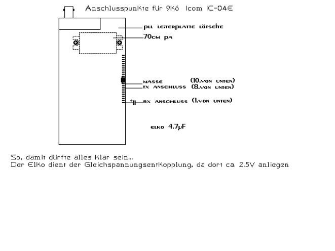 Ausführlichere Erklärung (Um das Gehäuse zu öffnen schraube man...) spare ich mir, da ich jedem Amateurfunker soviel Geschick zutraue..hi Das ganze funktioniert ganz gut, allerdings sind noch keine Langzeiterfahrungen bekannt.
Gewährleistung, welcher Form auch immer, wird natürlich nicht übernommen.
This modification is read 594 times.
top of page
01-04-2001
(IC-1200) Expanded RF 870 - 960 MHz for ICOM IC-1200
Author: John kb2ljj
1.Remove power and antenna.
2.remove screws and open the radio.
3.Locate and CUT resistor R-52 on logic " A " unit.
4.Install NEW antenna connector to position J2 on RF board. Note: a different antenna is required for the 870-960 bands.
5.Reassemble the radio.
6.Reset the microprocessor. ( Hold down the tuning control and Turn the power ON ) or ( Insert a toothpick in hole in the corner of the bottom cover.)
Adjustement: R-8 Low TX power and Hi TX power All the MODS are captured by Packet. KB2LJJ
73s John kb2ljj
This modification is read 353 times. |
top of page |

19-07-1998
(IC-1271) VOX of an IC-271,471,1271 usable for FM
How to make the VOX of an IC-271,471,1271 usable for FM :
1'st type of "main-board" :
The only thing to be done is to add a diode such as 1n4148 or bax13 on the MAIN board on the position D74 When D74 is inserted ... the vox works in FM also.
The diode is on the shematic diagram of the Main board but is not mounted on the pcb in the factory.
73's de stefaan ON4BY @ ON4HU 16/03/1990 18.31 h
2'nd type :
(On this board a D74 is present (near PAand RF-YGR- Unit)) (It might be not present in the plans !)
Disconnect the cathode of D69 from it's old postition. It's new position is the cathode of D50 or D51
name |
! position on main board |
! (old) function |
! |
D69 |
! near "CW-DELAY". |
! "FM -VOX-OFF" |
! FM 8V |
D50 |
! near "RF-YGR-Unit" |
! "USB-VOX-ON" |
! USB8V |
D51 |
! near "RF-YGR-Unit" |
! "LSB-VOX-ON" |
! LSB8V |
20/03/1990 16.52 h |
|
|
|
This modification is read 572 times. |
|
top of page |
|
30-03-2001
(IC-1271) RAM Card Backup Battery Replacement Instructions
Author: ICOM
In the early 1980s Icom America marketed a group of transceivers and radios that utilized the latest state-of-the-art computer technology to enhance the operation of the radios. This technology improvement allowed hams to afford a reasonably priced high performance transceiver which until then was only available on units costing much more. Features now available to the hams included: higher frequency stability, better frequency resolution, digital frequency display, almost instant recall of saved frequencies (memory channels), quick mode signal processing and built in tones and offsets for the rapidly emerging repeater operation.
Implementation of all these features required a CPU with associated logic circuitry. In the early 80s, the most cost effective way to implement data processing and memory functions was through a DRAM (Dynamic Random Access Memory) to control the CPU. This DRAM was a volatile memory integrated circuit which required a lithium battery to retain its instruction set. The following receivers and transceivers had such RAM units:
IC-271 ; IC-471 ; IC-1271 ; IC-745 ; IC-751/A ; IC-R71A
The lithium batteries in these units typically lasted about 5 to 7 years before replacement was required. This was specifically noted in each of the Owners Manuals for the products.
This lithium battery can be replaced by the radio owner if care is used. The following is a recommended procedure to accomplish this:
Procedure
1.Disconnect the power cable from the radio, and take the cover off.
2.Unplug the RAM board and remove it from the radio.
3.Temporarily solder a 3 Volt DC battery source across the existing battery terminals (see suggested connection points on the circuit board pictures).
4.Unsolder the old lithium battery and replace it with a new one. (BR2325 1HC, ICOM stock number 945 03112)
5.Unsolder your temporary 3 Volt DC source.
6. Reinstall the RAM board into the radio.
Cautions
1.Do not use an AC powered 3 Volt DC source, your grounded soldering iron tip could short out the battery (+) terminal. Use a 3 Volt battery DC source only (2 alkaline cells for example).
2.Do not solder the external DC wires directly to the lithium battery tab pads. If you do so, you will not be able unsolder the battery without having the wires drop off.
3.If by accident you lose power to the RAM unit it must be sent to Icom America for reprogramming.
4.Be careful not to damage or bend the connector pins on the radio side while removing or reinstalling the RAM card.
Pictures
There are two versions of the ICOM RAM boards. Both are identical in operation, and they are interchangeable. The differences are in the circuit board layouts only. Note that the black and red wires visible on these images are the suggested way of connecting the external DC backup voltage while the battery is being replaced. The wires are not a part of the RAM card, and should be removed when the battery replacement procedure is complete. Refer to the replacement procedure outlined above.
RAM card version A images:
RAM card version B images:

This modification can also be found at ICOM's own homepage on the following URL: "RAM Card Backup Battery Replacement Instructions"
This modification is read 595 times.
top of page
19-07-1998
(IC-1275) IC-1275 Freq. steps mod
Titolo: Tuning steps change for all mode Icom IC-275/475/575/1275
The IC-275/475 FM-Step selectmatrix use these diodes on the front unit: (type 1SS53) D41, D42, D43, D44, (D45), D46
Note: diode D45 is not present but solder holes exist for it on the board just between D44 e D46
installed diodes are marked with X :
|
|
|
|
(*) |
|
(*) |
|
|
|
|
|
|
D41 D42 D43 D44 D45 D46 D48 |
Steps |
DB4 DB5 DB6 DB7 |
||||||||||
. . . . . . |
. |
10.0 |
Hz |
|
|
|
|
|||||
. |
. |
. |
X . . |
. |
100.0 |
Hz |
1 |
0 |
0 |
0 |
||
. |
X . . . . |
. |
1.0 |
KHz |
0 |
0 |
1 |
0 |
||||
|
|
|
X |
. |
X |
. |
5.0 |
KHz |
1 |
0 |
1 |
0 |
. |
. |
. |
. |
X . |
. |
10.0 |
KHz |
0 |
1 |
0 |
0 |
|
. |
. |
. |
(*) |
X |
X |
. |
12.5 |
KHz |
(*) |
1 |
1 |
0 |
. . . . . . |
X |
25.0 |
KHz |
0 |
0 |
0 |
1 |
|||||
X |
. |
X . . . |
. |
1.0 |
MHz |
0 |
1 |
0 |
1 |
|||
(*)
To set a step of 12.5 KHz in FM mode (TS button off) it is not necessary disconnect the diode D44, just insert the diode D45 (IN4148 or similar) near D44 and "voil? les jeux sont faits".
Unscrew the two lateral screws and unlock the front panel.
Remove also all the connectors of the front board and after that unscrew ALL the screws of the metallic shield covering the front board. It seems too much complicated insert the diodes from the component side of the front board, so it is better insert D45 from the solder side.
This modification is read 537 times.
top of page

27-10-1998
(IC-1275) Power control modification
Problem:
The power control circuit in IC-x75 is an ALC circuit. ALC circuits suffers from several drawbacks:
●slow reaction time due to time constants
●insufficient regulation due to low feed-back factor
These factors gives the problem that if the average power has been set to a low value (e.g. for driving a HPA), peak power can still be in the order of 3-4 dB higher. This leads to either considerable side band distortion or a low average power output.
note: If you are always using your transceiver barefoot, without connecting any PA or transverter, this modification will offer no benefit.
Solution:
The solution to these problems is to use a simple forward gain regulation without the feed back circuit of the ALC. The original ALC is still kept for SWR protection only.
The ALC is working on gate 1 of Q13, which is a IF amplifier (9 or 10.75 MHz). The new power regulation uses gate 2 of Q13. Therefore the two circuits can exist in parallel.
The modification should also give you a bigger dynamic range in the power regulation (lowest power < 5W on the IC-x75H).
Implementation:
●replace R87 (470k) with 100k
●cut "POCO" wire (pin 3, P1/J1, MAIN, orange) at the plug (P1)
●connect the "POCO" wire to gate 2 of Q13 (e.g. via top of R87)
●adjust R250 (SWR protection), R256 (low power level) & R259 (high power level) fully counter-clockwise. (this will give you full SWR protection, but cancels the ALC in normal operation).
●put the front plate RF PWR in full output position (clockwise) and adjust R82 (Q13 output attenuator) until you have the nominal output power (initially the output power will be higher because you removed the regulation, but the PA will be saturated).
●the balance between FM, CW & SSB output can be adjusted with R137 (CW carrier level) & R105 (FM carrier level).
●other interesting adjustments: R135 (mixer balance i.e. SSB carrier suppression), R133 (TX BFO output level).
This modification is read 535 times.
top of page
27-10-1998
(IC-1275) Restoration of pass band tuning
Problem:
ICOM has chosen to remove the PBT in the later models, and replace it with a "data level adjustment". This change removes the possibility to profit from the PBT in case of QRM or to use the PBT as a cheap CW-filter.
Furthermore the two extra IF-mixings is done with only a minimum of filtering, making the receiver very susceptible to spurious IF breakthrough. This is often heard as high-pitch tones or as a high IF noise level.
Solution:
The solution is to re-wire the "data level" potentiometer so that it adjusts the PBT VXO-oscillator, and to re-install FI3. FI3 is a 455kHz ceramic SSB filter and can be bought under the type number: MURATA CFJ 455 K6.
Implementation:
●remove the capacitor (C61) fitted in place of FI3
●solder in FI3
●readjust R72 for proper IF gain
●cut wire PBTV (pin 4, P1/J1, MAIN, yellow) about 5cm from the plug (P1)
●cut wire AMO2 (pin 3, P2/J18, MAIN, red) close to the plug (P2)
●cut wire AMO3 (pin 4, P2/J18, MAIN, metal baird) close to the plug (P2)
●connect PBTV wire (the end not connected to the plug) with AMO2 wire (the end not connected to the plug)
●connect AMO3 (the end not connected to the plug) to +8V e.g. by tapping (pin 1, J4, MAIN, brown).
●connect the wire stubs on the plug (AMO2 & AMO3) together is you wish to use external modulation input for PACKET etc.
●adjust the coil next to X2 (PBT VXO) for correct middle PBT setting
This modification is read 520 times.
top of page
27-10-1998
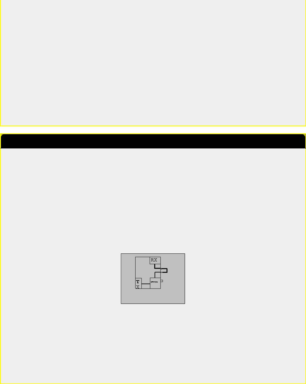
(IC-1275) Splitting into RXand TX paths
Problem:
This is a general transceiver problem. If you want to use the transceiver as part of a bigger setup (i.e. with external PA & preamp or with a transverter), it is convenient to have separate access to the RX and the TX of the transceiver. Otherwise you need two coaxial switches every time you add a new accessory. With split RX/TX paths you only need one switch - at the antenna. Furthermore split RX/TX paths eliminates the need for a change-over sequencer.
On the other hand it is also nice to have the transceiver working normally when you are using it barefoot.
Solution:
The solution is to jump wire the RX path (between RX and the RX/TX switching) trough the rear side of the transceiver with 2 BNC connectors. In normal state these connectors are connected via a short cable. In case you need to "split up" the transceiver, you remove the short coax cable, and you obtain direct access to the RX. The TX is still available using the common connector.
note: If you are always using your transceiver barefoot, without connecting any PA, preamp or transverter, this modification will offer no benefit.
Remove the back cover. If you place the holes for the BNC connectors next to and aligned with the two existing DIN-connectors, then ICOM have left enough space on the inside for the connections. You can also add other desired outputs like a phono plug for AF OUT.
The RX cable runs between J4 on the RF YGR PCB and the PA unit.
note: In my IC-275H the PIN-diode for the FM RF gain is shared with the RX/TX switch and placed in the PA unit. This means that the control voltage passes through the RX cable.
Therefore the breaking of the RX cable will cancel the FM RF gain function (the SSB/CW RF gain is working on the AGC and is not affected). The solution is to install a new PIN-diode (D5) on the RF-YGR PCB. The PCB has already room for it. To avoid shortcircuiting the control voltage the jumper placed in stead of C86 on the RF-YGR PCB, should be replaced by a 1nF capacitor.
This modification is read 523 times.
top of page
27-10-1998
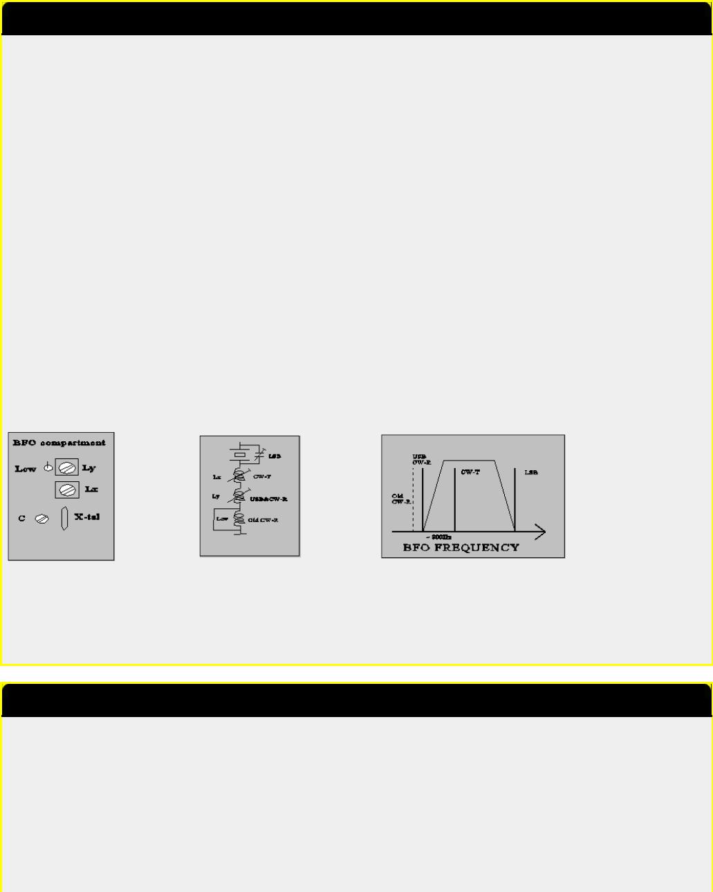
(IC-1275) Modification of cw pass band (BFO)
Problem:
In these transceivers ICOM has chosen to shift the CW passband up 200 Hz compared to the SSB passband. This makes it more difficult to copy SSB signals in CW mode.
Solution:
The extra BFO coil that is added in CW-R is short-circuited, and the BFO is re-adjusted for proper CW RX/TX-tracking and for preferred USB/CW passband.
Implementation:
● short-circuit Lcw in the BFO compartment.
For readjusting the BFO you need another transceiver (TRX2) with correct tracking.
1.Receive on TRX2 and transmit in CW. Adjust the VFO (with the RIT off !) of TRX2 until you have the desired side tone in CW mode. (e.g. 800 Hz - can be found by beating the tone with the side tone oscillator).
2.Transmit on TRX2 and adjust Ly (CW-R) until you have the desired side tone in CW mode. (you are setting the ~800Hz difference between CW-R & CW-T).
3.Adjust Lx (CW-T) for preferred USB/CW receive passband.
You might have to repeat the tuning once again, as there is some interaction between the adjustments (diode switching for high impedance RF circuits are not perfect !). If you would like to adjust the LSB passband, this should be done by adjusting the capacitor C, before adjusting the coils.
Note: The BFO coils are switched in successively to give the required offset from the LSB frequency. Therefore adjusting CW-T also changes USB/CW-R.
Re-adjusting all of the BFO frequencies is a good idea in any case to compensate for crystal aging. If the passbands sound different in LSB and USB it is a sure sign of mis-alignment due to crystal drift - they should be more or less the same.
This modification is read 513 times.
top of page
27-10-1998
(IC-1275) Disabling of SBB squelch
Problem:
Squelching is nice to have in FM mode, but it doesn't really work for SSB, where you will be looking for weak signals. Therefore you have to adjust the squelch level every time you change mode. Furthermore I enjoy using FM as a monitoring mode on the SSB calling frequency, so changing the mode happens quite often.
Solution:
The solution is quite simple. Just cut the connection to the SSB input of the squelch circuit in some way.
Implementation:

The easiest way to break the connection is to connect the base of Q7 to ground. The base is the lead facing into the centre of the PCB.
Date: 04-01-2002 |
User comment |
From: Hiroki Ohashi,JI2EVL |
Subject: other methode for confortable ssb SQL |
|
|
|
|
|
|
|
|
R18 (33k)on Main Unit change 68k. And You set SQL position between 9 and 10 o'clock. You can operate sql open on SSB mode, and sql able on FM mode.
It align that FM SQL position to 9 O'clock from 10 o'clock.
This modification is read 522 times.
top of page
27-10-1998
(IC-1275) Very fast AGC
Problem:
For some modes of weak signal communication, it can be desireable to have a very fast AGC (e.g. meteor bursts with a sharp rise and a long weak "tail"). The standard fast AGC has a time constant of about 2 secs (!), which also means that a noise pulse can mute you for quite some time.
Note: Never use the noise blanker when receiving high speed CW (Meteor Scatter). The noise blanker mistakes the high speed keying for noise pulses, and will seriously corrupt the signal.
Solution:
The solution is to move the "AGC fast" capacitor (C19) to replace the "AGC slow" capacitor (C20). You will loose the "AGC slow" option, but I find "AGC fast" adequate for most signals.
Another solution is to switch out the "AGC fast" capacitor (C19) seperately, but then you will get the problem of finding an appropiate front plate switch. I already tried to use the DATA button, but it cannot be activated in CW.
Note: a strong signal will be seriously distorted in AGC OFF mode.
Implementation:
●remove C20
●move C19 to the replace C20
This modification is read 521 times.
top of page
27-10-1998
(IC-1275) SSB RF Gain
Problem:
The RF GAIN function is different in FM and in SSB/CW modes. In FM mode the RF GAIN controls a PIN-diode at the input of the preamp. In SSB/CW the RF GAIN simply activates the IF AGC.
The use of the preamp input attenuator (the PIN-diode) can be useful also for SSB/CW e.g. if you have connected a mast head preamp with excessive gain. In this case the attenuator will help you to adjust the signal levels at the mixer, and thus reduce intermodulation and blocking.
Solution:
The solution is to remove the SSB/CW RF GAIN for SSB/CW (this function is of little use anyway), and enable the FM RF GAIN even in SSB/CW.
Implementation:
● Cut the lead (FM8V) conneted to (pin5, J6, potmeter PCB, green) about 4 cm from the plug

●Connect the short plug end with R14 (on the potmeter PCB) by soldering it to the end that is connected to the plug (+8V) This will enable the FM RF GAIN in SSB/CW.
●cut R30 open
This disables the SSB/CW RF GAIN, and you now have a variable input attenuation with a dynamic range of 10dB (IC275 with MI308/1nF) to 16 dB (IC475).
Note: The IC-275 might have a shared PIN diode for FM RF GAIN and TX/RX switching. If you choose to split up the RX/TX paths, you must install a new PIN diode (MI301 or equivalent) on the RF YGR PCB to implement this modification. See the note under the section dealing with spliting the RX/TX paths.
This modification is read 515 times.
top of page
27-10-1998
(IC-1275) Tuning speed
The tunning speed is set to a defaults of 100Hz, 1kHz, 5kHz or 1MHz depending on front plate setting and mode. These settings can be manipulated by D41 - 46 at the front plate. At least a setting of 10kHz is also available.
This modification is read 510 times.
top of page
27-10-1998
(IC-1275) Frequency range & CTCSS tones
The IC-275 have capability to cover 138 - 174 MHz and the IC-475 has capability to cover 430 - 450 MHz. Because of hardware restrictions they might not be fully up to specifications in all of the band, but an extended range can be interesting for e.g. use with a transverter. It seems that the IC-275 has a parallel wide band preamp, that can be switch via the WBT pin on RF-YGR PCB.
In the European versions the transceivers are wired for 1750 Hz repeater call, and they have no CTCSS capability. The transceivers have a built-in CTCSS encoder, so these functions can be restored.
Both of these version dependent functions can be set by the diode matrix: D20 - D24 in the logic unit. I do not know the exact mapping, but a lot can be derived from studying the different frequency ranges and the diode matrix coding table found on the schematic diagram.
This modification is read 527 times.
top of page
20-04-2000
(IC-1275) IC 475H / 1275E mod for 9k6 (G3RUH) use
This is original the 9600 baud mod for the IC-475H. Yann - F1NGP f1ngp@wanadoo.fr.MODIFICATION.NET has reported this to me.
I've tried the MODS for 9600bds for my ICOM IC-475H . Working OK . I've tried to build the same mod on my 23cm ALL-MODE ICOM IC-1275E as the MAIN UNIT is the same as the 475 ... ALL WORKING OK !
Thanks to Yann.
The original ICOM IC-475H 9600 baud modification.
Warning:
I'm writing this message to help out owners of Icoms 475 H to modify their transceivers for use with a G3RUH modem. I will not take any responsability if you destroy your transceiver while doing this modification. This modification requires that you have a minimum experience in soldering and electronics. If you feel that you cannot undertake this modification, don't even try it and leave it up to someone else!

Reception of FSK signal:
The reception has to be taken directly off the demodulator chip. This is the chip referenced as IC6 (MC3357P) on the electronics diagram.
Demodulator output is on pin 9 of this chip. You will have to run a SHIELDED wire from this pin to the outside of your transceiver. I've done this by connecting it to pin 11 of J4 (AQS socket on the back). This pin is originally unused. But this is not as easy as it sounds; you will have to unscrew both sides of the transceiver and undo a lot of parts to finally solder on a very small plug! Be careful here.
Transmission of FSK signal:
The FSK signal is simply injected on pin 2 of the AQS socket. BUT, as you will see on the electronic diagram, this signal goes through a variable resistor (R152) and a capacity (C142). So you might encounter two problems: not enough and/or distorted modulation. In my case, I used a MFJ 9600 Bauds card and I had to put the level almost to the maximum on this board, while also putting the variable resistor to the minimum! The capacity on the other hand is very very bad for the modulation of the FSK signal as the transceiver should respond to DC! My solution: simply short circuit the capacity (C142). This is most easily done directly on the components side of the circuit board, since it's very difficult to take it out of the transceiver.
Other signals:
You will be able to put the PTT line to pin 6 and the ground to pin 1 of the AQS socket. You will also notice that on pin 13, you
have 13.8 V available. This can be used to power the TNC for example...
I have now a much more stable 9k6 signal than before, when I still had the C142 in the line. Although, this was reportedly been working for other people, it simply didn't for me! Maybe you can avoid short circuiting the capacity, so try it first (although I doubt it!).
I hope this will help somebody and if you have any more questions, don't hesitate to contact me at my homeBBS: HB9VBC @ HB9IAP.SROM.CHE.EU
This modification is read 527 times.
top of page
19-07-1998
(IC-2) Modification For IC-2AT
If you have studied the schematic diagram for this radio, you will notice that pins 15 and 16 are not indicated on the programmable divider chip IC1 (TC9122).
By simply connecting pin 15 thru a switch to pin 1, you will be able to move the radio up in frequency by 10 MHZ.
Some of these radios were sold without covering 140-150 MHZ.
The modification for this extended coverage is described below:
1.Open up the radio and locate the FLEXIBLE BOARD, this connects the thumbwheel switches to the MAIN BOARD.
2.At the MAIN BOARD end of the FLEXIBLE BOARD, add a jumper at location C4. There should already be a jumper at location C2.
3.At the thumbwheel switch end of the FLEXIBLE BOARD, remove the jumper which connects C3 and COM.
4.Reassemble the radio. Coverage is now 140-150 MHZ.(MARS/CAP)
Now, if you activate the switch described above, the radio will now operate in the 150-160 MHZ range, after L3 adjustment, described below.
OPERATION and L3 ADJUSTMENT:
1.Activate switch and dial up a known active frequency.
2.Adjust L3 until PLL locks up and radio begins receiving. (you need an active frequency to tell when this happens)
3.To return to 140-150 MHZ, repeat above steps with switch off.
NOTES and DISCLAIMER
1.Drill a hole in the case of the radio so that L3 can be adjusted from outside of the radio.
2.The above information is presented for educational purposes only, and is not an endorsement of any particular practice.
3.This MOD has been in operation for 6 years with no ill effects on the radio
4.This MOD courtesy N2MOD.

This modification is read 1316 times.
top of page
19-07-1998
(IC-2) Low audio speaker mike on IC2A, 3A, 4A OR 02AT
If you own one of the IC2A, 3A, or O2AT series Hand-helds, you may be interested in reading on. I know my hearing is pretty good, but have you ever tried to listen to the audio coming out of your speaker mike on the above ICOM's? For the most part, it's pretty low. I may be the last guy to figure out a cure for this, but here it is anyway. On the O2AT, etc., there is a groove on the back near the top of the rig that is just the right size to accept the HM9 speaker mike turned 90 degrees so that the mike plug fits in that groove in the rear of the rig. Thus alllowing all the audio to be heard from the internal speaker of the rig, usually much better than the speaker mike.
Now, in the case of the 2A series, etc., the fix is more complex. These rigs don't have that handy groove built in, so I decided a groove had to be made to accept this configuration. I thought long and hard about a minute, before getting the "Dremel" out and making my own slot or groove. It works well on both hand-helds I have. In fact, you can hook up an external speaker for even more loudness in the auto. So, give it a try or see me for a demo.
This modification is read 1012 times.
top of page
19-07-1998
(IC-2) ICOM IC-2AT internal antenna connection problem
I routinely use a half wave ant. On my IC-2AT handheld. When collapsed, the antenna has the same gain ( loss ) as a rubber duck antenna while giving me greater range when fully extended.
There is a certain amount of movement of the center pin of the bnc connector with the half wave antenna on the handheld.
This movement causes fatigue fracturing of the wire connecting the printed circuit board to the bnc connector.
After numerous failures, i used the braid of RG-174 coax to make the connection.
First remove the bnc from the radio and brake off the non-used ground lug.
The pin of the bnc should beplaced into the end of the braid.
A thin pice of wire is then wrapped around the braid 3-4 times, and then secured, then soldered. Reinstal the bnc and dress the braid to the solder pad on the printed circuit board and solder. Do not heat the braid to log while soldering, as solder will be drawn up, making it stiff and subject it to fatigue fracturing...
This modification is read 1016 times.
top of page
19-07-1998
(IC-2) ICOM IC-2GAT ext frq for Transmit
Out-of-band transmit mod for ICOM IC-2GAT handheld 2M transceiver (copied from packet radio; origin unknown:)
Back side of display board:
|
_____________________________________ |
|
|
|||
| |
|
|
|
D505 |
|
|
| |
|
D507 |
D504 |
___ |
|
|
| |
|
___ |
___ |
|___| |
|
| |
| |
|
|___| |___| |
|
|
-- + -- |
|
| |
D506 |
|
|
Q506 |
| |
| |
| |
_o_------ |
|
_o_ |
| |
hole for |
|
| |
|___| |
| |
|
|___| |
| |
on/off-vol |
| |
o o |
| |
|
o o |
| |
control |
| |
|
| |
|
| |
|__________________ |
|
| |
|
|
-----|<--------- |
|
| |
|
| |
|
add diode: 1N914 or equiv. |
|
| |
||
| |
|
|
|
|
|
| |
Connect diode between top lead of D506 and lower right lead of Q506 as shown.
Notes:
D506 may be absent. If not, remove it.
Reset CPU if needed.

A friend did this and his IC-2GAT can now transmit 138 to 178 MHz (no RF power output measurements were made). He did no retuning, and did not have to reset the CPU. He used a tiny axial-lead glass diode, replaced its leads with wire-wrap wire, and encased it in shrink-tube. The operation requires a super-tiny soldering iron. Observe CMOS soldering precautions: Unplug the iron and ground the tip before touching the circuit.
Remember: Except for MARS and CAP, it is illegal to transmit outside the ham bands with non-type-approved equipment.
This modification is read 1076 times.
top of page
19-07-1998
(IC-2) IC-2AT, If transmit RF indicator notwork properly
Model: |
IC Micro 2AT |
|
Division: |
Amateur |
|
Note: |
This service bulletin is meant for technical per- |
|
|
sonnel with experience working on solid state com- |
|
|
munications equipment. Damage caused by im- |
|
|
properly installing this modification may cause |
|
|
ICOM to charge |
for subsequent repairs to the |
|
product. ICOM |
does not warrant this modification. |
Bulletin #: |
8988-002 |
|
Date: |
March 29, 1988 |
|
Subject: |
If transmit RF |
indicator is not reading properly |
Procedure
1.Disassemble the radio to gain access to the RF Board.
2.Replace the following parts on the RF Board:
Reference |
Original |
New |
ICOM |
Designator |
Value |
Value |
P/N |
Q309 |
2SA 1162 |
1SS 196 |
912-00965 |
D309 |
1SS 211 |
2.2Meg 1/8W |
|
R345 |
|
Remove this part |
|
C349 |
|
Remove this part |
|
3. Reassemble the radio.
This modification is read 990 times.
top of page
19-07-1998
(IC-2) Icom IC-2GXAT open RX
>David, For the IC-2GXAT receiver opening do the following steps as listed.
>
>1. Turn off the radio
>
>2. Press and hold the " Function, Scan and Dupe keys "
>
>3. While holding those keys turn on the radio.
>
>4. WAIT until the display returns to normal then continue to hold the
>keys for about 2 seconds
>after the display has returned to normal before releasing the keys
>5. The receiver is now opened up and will cover 138 to 179 Mhz or so.
>It WILL NOT do aircraft AM receive nor tune into that frequnecy range.
That's an interesting note. I recently did this to my rig (Purchased last may, low serial number) and it receives from about
 Loading...