


IC-R6
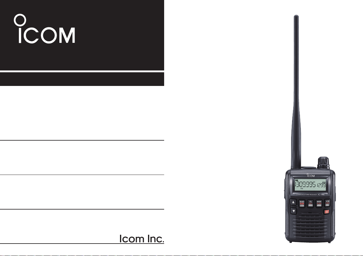
INSTRUCTION MANUAL
iR6
COMMUNICATIONS RECEIVER
This devi ce co mpl ies w ith Part 15 of the FCC Rules. Operation
is s ub je ct to the follo wi ng two conditions: (1) this device may
not cause harm ful interfere nce, a nd (2) this device must accept
any interference received, including interference that may cause
undesired operation.
WAR NI NG: MOD IF ICATI ON OF TH IS DE VIC E TO RE CE IVE
C E L L U L A R RA DI O T E L E P H ON E SE RVIC E SI G N A L S IS
PROHIBITED UNDER FCC RULES AND FEDERAL LAW.

i
FOREWORD
Thank yo u for purchasing this Icom pr oduct. The IC-R6
communications receiver is designed and built with Icom’s
superior technology and craftsmanship. With proper care,
this product should provide you with years of trouble-free
operation.
We want to take a moment of your time to thank you for mak-
ing your IC-R6 your radio of choice, and hope you agree with
Icom’s philosophy of “technology first.” Many hours of research
and development went into the design of your IC-R6.
D FEATURES
m Covers 0.100–1309.995 MHz* wide
frequency range
*
Some frequency bands are prohibited
, depending on the
receiver version
m External power supply operation
m 1300 memory channels with 22 banks
available
m 150 mW* AF power with BTL (bridge-tied
load) amplifier
*At 10% distortion with a 16 Ω load (internal speaker)
IMPORTANT
READ ALL INSTRUCTIONS carefully and completely
before using the receiver.
SAVE TH I S INSTRUCTION M A NUAL — This
instruction manual contains important operating instructions
for the IC-R6.
EXPLICIT DEFINITIONS
WORD DEFINITION
R DANGER!
Pers onal deat h, ser ious i njur y o r an
explosion may occur.
R WARNING!
Personal injury, fire hazard or electric
shock may occur.
CAUTION Equipment damage may occur.
NOTE
Recommended for optimum use. No risk
of personal injury, fire or electric shock.
Icom, Icom Inc. and the Icom logo are registered trademarks of
Icom Incorporated (Japan) in Japan, the United States, the United
Kingdom, Germany, France, Spain, Russia and/or other countries.
Microsoft, Windows and Windows Vista are registered trademarks
of Microsoft Corporation in the United States and/or other countries.

ii
RWARNING! NEVER operate the receiver with a
earphone, headphones or other audio accessories at high
volume levels. Hearing experts advise against continuous
high volume operation. If you experience a ringing in your
ears, reduce the volume level or discontinue use.
RWARNING! NEVER operate the receiver while
driving a vehicle. Safe driving requires your full attention—
anything less may result in an accident.
RWARNING! NEVER connect the receiver to an AC
outlet. This may pose a fire hazard or result in an electric
shock.
RWARNING! NEVER throw a battery cell into a fire
since as internal battery gas can cause explosion.
RWARNING! NEVER disassemble the battery cell.
If the battery cell’s internal material (electrolyte liquid) gets
into your eyes, wash your eyes with water and obtain treat-
ment from an eye doctor immediately.
NEVER connect the receiver to a power source of more
than 6.3 V DC directly. This will damage the receiver.
NEVER connect the receiver to a power source using
reverse polarity. This will damage the receiver.
NEVER expose the receiver to rain, snow or any liquids.
The receiver may be damaged.
NEVER operate or touch the receiver with wet hands. This
may result in an electric shock or damage the receiver.
NEVER solder the battery cell. This may damage the bat-
tery.
DO NOT use or place the receiver in direct sunlight or
in areas with temperatures below –10°C (+14˚F) or above
+60°C (+140˚F).
DO NOT use harsh solvents such as benzine or alco-
hol to clean the receiver, because they can damage the
receiver’s surfaces.
Even when the receiver power is OFF, a slight current still
flows in the circuits. Remove batteries from the receiver
when not using it for a long time. Otherwise, the installed
ba tter ies w ill b ecom e exhau sted, and will need to be
recharged.
PRECAUTIONS

iii
FCC INFORMATION
• FOR CLASS B UNINTENTIONAL RADIATORS:
This equipment has been tested and found to comply with
the limits for a Class B digital device, pursuant to part 15 of
the FCC Rules. These limits are designed to provide reason-
able protection against harmful interference in a residential
installation. This equipment generates, uses and can radi-
ate radio frequency energy and, if not installed and used in
accordance with the instructions, may cause harmful inter-
ference to radio communications. However, there is no guar-
antee that interference will not occur in a particular instal-
lation. If this equipment does cause harmful interference to
radio or television reception, which can be determined by
turning the equipment off and on, the user is encouraged to
try to correct the interference by one or more of the following
measures:
• Reorient or relocate the receiving antenna.
• Increase the separation between the equipment and
receiver.
• Connect the equipment into an outlet on a circuit differ-
ent from that to which the receiver is connected.
• Consult the dealer or an experienced radio/TV techni-
cian for help.
OPERATING THEORY
El e ctrom agnet i c radia tion, wh i ch has fre quenc i es of
20,000 Hz (20 kHz*) and above, is called radio frequency
(RF) energy because, it is useful in radio transmissions. The
IC-R6 receives RF energy from 0.100 MHz* to 1309.995
MHz and converts it into audio frequency (AF) energy which
in turn actuates a loudspeaker to create sound waves.
AF energy is in the range of 20 to 20,000 Hz.
* kHz is an abbreviation of kilohertz or 1000 hertz, MHz is abbrevi-
ation of megahertz or 1,000,000 hertz, where hertz is a unit of fre-
quency.
OPERATING NOTES
The IC-R6 may receive its own oscillated frequency, result-
ing in no reception or only noise reception, on some fre-
quencies.
The IC-R6 may receive interference from extremely strong
signals on different frequencies or when using an external
high-gain antenna.
CAUTION: Changes or modifications to this device, not
expressly approved by Icom Inc., could void your authority
to operate this device under FCC regulations.

iv
1
2
3
4
5
6
7
8
9
10
11
12
13
14
15
16
1
2
3
4
5
6
7
8
9
10
11
12
13
14
15
16
TABLE OF CONTENTS
FOREWORD ………………………………………………… i
IMPORTANT ………………………………………………… i
EXPLICIT DEFINITIONS …………………………………… i
PRECAUTIONS ……………………………………………… ii
FCC INFORMATION ……………………………………… iii
OPERATING THEORY …………………………………… iii
OPERATING NOTES ……………………………………… iii
TABLE OF CONTENTS ………………………………… iv–v
SUPPLIED ACCESSORIES ………………………………… v
QUICK REFERENCE GUIDE ���������� I–VII
n Preparation ……………………………………………… I
n Your first scanning experience ……………………… III
n Memory programming ……………………………… IV
n Programmed scan operation ………………………… V
1 PANEL DESCRIPTION ������������ 1–4
n Front, top and side panels ………………………… 1
n Function display ……………………………………… 3
2 BATTERY CHARGING ������������ 5–8
n Battery installation …………………………………… 5
n Caution ………………………………………………… 5
n Battery charging ……………………………………… 7
3 FREQUENCY AND CHANNEL SETTING ��� 9–12
n VFO and memory channels ………………………… 9
n Frequency band selection …………………………… 9
n Setting a frequency …………………………………… 11
n Setting a tuning step ………………………………… 11
n Selecting a memory channel ………………………… 12
n Lock function ………………………………………… 12
4 BASIC OPERATION ������������ 13–17
n Receiving ……………………………………………… 13
n Setting audio volume ………………………………… 13
n Squelch level setting ………………………………… 14
n Receive mode selection ……………………………… 14
n Monitor function ……………………………………… 15
n Attenuator function …………………………………… 15
n Duplex operation ……………………………………… 16
n Dial select step ……………………………………… 17
5 MEMORY CHANNELS ����������� 18–27
n General description …………………………………… 18
n Selecting a memory channel ………………………… 18
n Memory channel programming ……………………… 19
n Memory bank setting ………………………………… 20
n Memory bank selection ……………………………… 21
n Programming memory/bank name ………………… 22
n Selecting display type ………………………………… 23
n Copying memory contents …………………………… 24
n Memory clearing ……………………………………… 25
n Transferring memory contents ……………………… 26
n Erasing/transferring bank contents ………………… 27
6 SCAN OPERATION ������������ 28–37
n Scan types …………………………………………… 28
n Full/band/programmed link/programmed scan …… 29
n Scan edges programming …………………………… 30
n Programming scan name …………………………… 31
n Programming other contents ………………………… 32
n Memory/all bank/bank link/bank scan ……………… 33
n Auto memory write scan …………………………… 34
17
v
n Skip channel/frequency setting ……………………… 35
n Scan resume setting ………………………………… 37
7 PRIORITY WATCH ������������ 38–40
n Priority watch types …………………………………… 38
n Priority watch operation ……………………………… 39
8 TONE SQUELCH AND POCKET BEEP ��� 41–44
n Tone squelch frequency/DTCS code setting ……… 41
n Tone/DTCS squelch operation ……………………… 43
n Tone scan ……………………………………………… 44
9 Set mode ���������������� 45–56
n General ………………………………………………… 45
n Set mode items ……………………………………… 46
10 OTHER FUNCTIONS ����������� 57–63
n Antenna selection …………………………………… 57
n [DIAL] function assignment ………………………… 58
n Auto power-off function ……………………………… 58
n Weather channel operation ………………………… 59
n Data cloning ………………………………………… 61
n Partial reset …………………………………………… 63
n All reset ……………………………………………… 63
11 CONTROL COMMAND ����������� 64–61
n General ………………………………………………… 64
n Data format …………………………………………… 64
n Command table ……………………………………… 65
12 FREQUENCY TABLE ����������� 67–74
n TV channels …………………………………………… 67
n VHF marine channels ………………………………… 70
n Weather channels …………………………………… 70
n Other communications in the USA ………………… 72
n Other communications— other countries ………… 73
13 MAINTENANCE �������������� 75–76
n Troubleshooting ……………………………………… 75
n CP-18A/E fuse replacement ………………………… 76
14 SPECIFICATIONS ��������������� 77
15 OPTIONS ������������������ 79
16 POCKET GUIDE ������������� 80–81
17 CE �������������������� 81–82
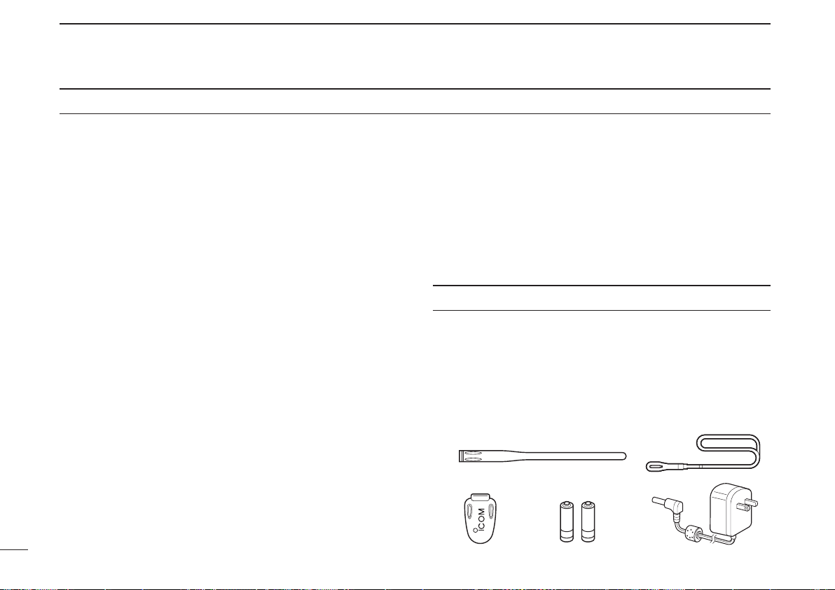
SUPPLIED ACCESSORIES
q Antenna ············································································ 1
w Hand strap ········································································ 1
e Belt clip ············································································· 1
r Ni-MH batteries*atteries* ······························································ 2
t AC adapter* ····································································· 1
* Not supplied, or the shape is different, depending on the receiver
version.
TABLE OF CONTENTS
q
w
e r t
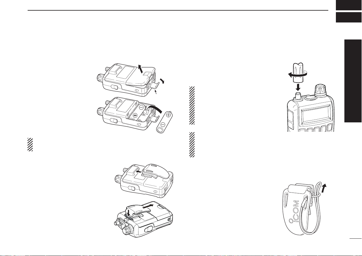
■ Preparation
D Battery installation
q Remove the b a ttery
cover from the receiver.
w Ins tall two A A ( L R6)
size Ni-MH or alkaline
cell batteries.
• Be sure to observe the
correct polarity.
• Charge the Ni-MH bat-
ter ies before use. (See
pa g e II f o r ch a rg i ng
instructions.)
Keep the battery terminals clean. It’s a good idea to clean
the battery terminals once a week.
D Belt clip
Convenie ntly attaches to yo ur
belt.
To attach the belt clip:
Slide the belt clip into the plastic
loop on the back of the receiver.
To detach the belt clip:
Hold down the tab (q), and slide
the belt clip in the direction of the
arrow (w).
D Antenna
Insert the antenna connector into
the antenna base and tighten the
antenna screw.
• NEVER carry the receiver by
holding only the antenna.
• When the jack is not in use,
keep the jack cover attached
to protect the connectors from
dust and moisture.
✔ For your information
Third-party antennas may increase receiver performance.
An optional AD-92SMA antenna connector adapter is
available to connect an antenna with a BNC connector.
D Handstrap
To facilitate carrying the receiver,
slide the hand strap through the
loop on the top of the belt clip.
Latch
q
w
I
QUICK REFERENCE GUIDE
Quick reference guide
II
QUICK REFERENCE GUIDE
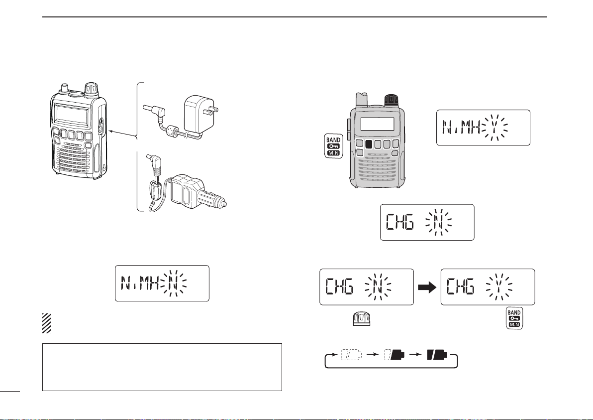
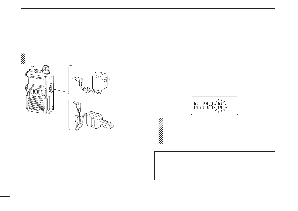
D Charging the battery
Receiver
CP-18A/E
Cigarette lighter cable
with DC-DC converter
BC-196SA/SD/BC-153SC
to a cigarette
lighter socket
The shape may
differ, depending
on the version.
to an AC outlet
to the [DC4.5V]
jack
q Install the Ni-MH batteries.
w Plug the AC adapter into an AC outlet.
e Insert the adapter plug into the [DC4.5V] of the receiver.
• The battery confirmation is displayed.
RWARNING!:
NEVER attempt to charge the alkaline batteries.
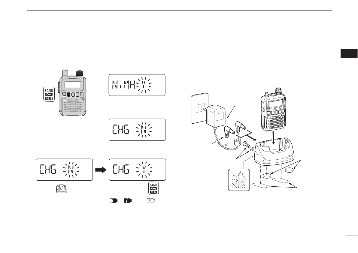
r Rotate [DIAL] to select “Y,” then push [BAND].
[DIAL]
• The charging confirmation is displayed.
t Rotate [DIAL] to select “Y,” then push [BAND] to start the
battery charging.
Rotate
Then, push
• The battery icon scrolls during charge.
• Both segments blink when completely charged.
NOTE: When no operation is performed for 10 seconds, the
receiver automatically skips these settings, and the receiver
cannot charge the batteries. In that case, remove the batteries
for more than 2 seconds and retry these setting from step q.
III
QUICK REFERENCE GUIDE
Quick reference guide
Now that you have your IC-R6 ready, you are probably ex-
cited to start listening. We would like to take you through a
few basic operation steps to make your first “Listennig Expe-
rience” enjoyable.
D About the default settings
The [DIAL] control function can be traded with the [p]/[q]
ke ys fun ctio n. How ever , in thi s QUICK REF EREN CE
GUIDE, the factory default setting ([DIAL] selects the oper-
ating frequency) is used for simple instruction.
D Basic operation
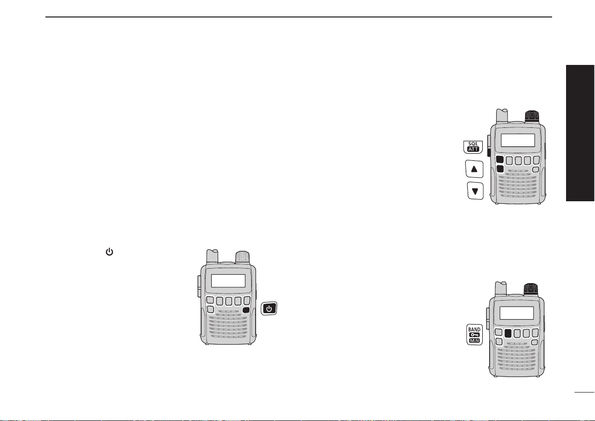
1. Turning ON the receiver
➥ Hold down [ ] for 1 second to
turn the power ON.
2. Adjusting audio level
➥ Push [p]/[q] to set a desired
audio level.
3. Adjusting squelch level
➥ W hile hold i n g d own [SQL] ,
rotate [DIAL] to set the squelch
level.
4. Setting a desired frequency
The tuning dial will allow you to dial in the frequency you
want to listen to. Pages 11 and 17 will instruct you on how to
set the tuning speed.
q Push [ BAND ] repea tedly t o
select a frequency band.
• While holding down [BAND], then
rotating [DIAL] will also select a
frequency band.
w Rotate [DIAL] to set the receive
frequency.
•
While holding down [FUNC], rotate
[D IAL] to selec t fr equencie s in
MHz steps.
■ Your first scanning experience
[DIAL]
[DIAL]
IV
QUICK REFERENCE GUIDE
■ Your first scanning experience (continued)
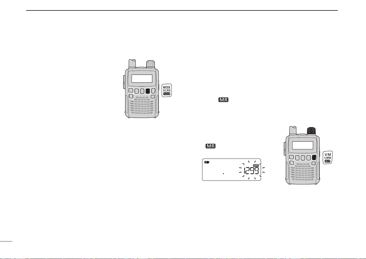
5. Receive mode selection
➥ Pu sh [M ODE ] repeat edl y to
select a desired receive mode.
• The FM, WFM or AM is selectable.
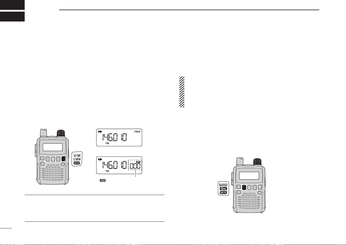
■ Memory programming
The IC-R6 has 1300 memory channels for storing often used
receive frequency, mode, etc.
1. Setting frequency
In the VFO mode, set a desired receive frequency and
receive mode.
• When the “ ” icon is displayed, push [V/M] to select the VFO
mode.
2. Selecting a memory channel
Ho l d dow n [S . M W ]( V / M ) fo r
1 second, then rotate [DIAL] to
select a desired memory channel.
• The “ ” icon and memory chan-
nel number blink.
3. Writing a memory channel
Hold down [S.MW](V/M) for 1 second until 3 beeps sound.
• The memory channel number automatically increases if you con-
tinue to hold down [S.MW](V/M) after programming.
[DIAL]
V
QUICK REFERENCE GUIDE
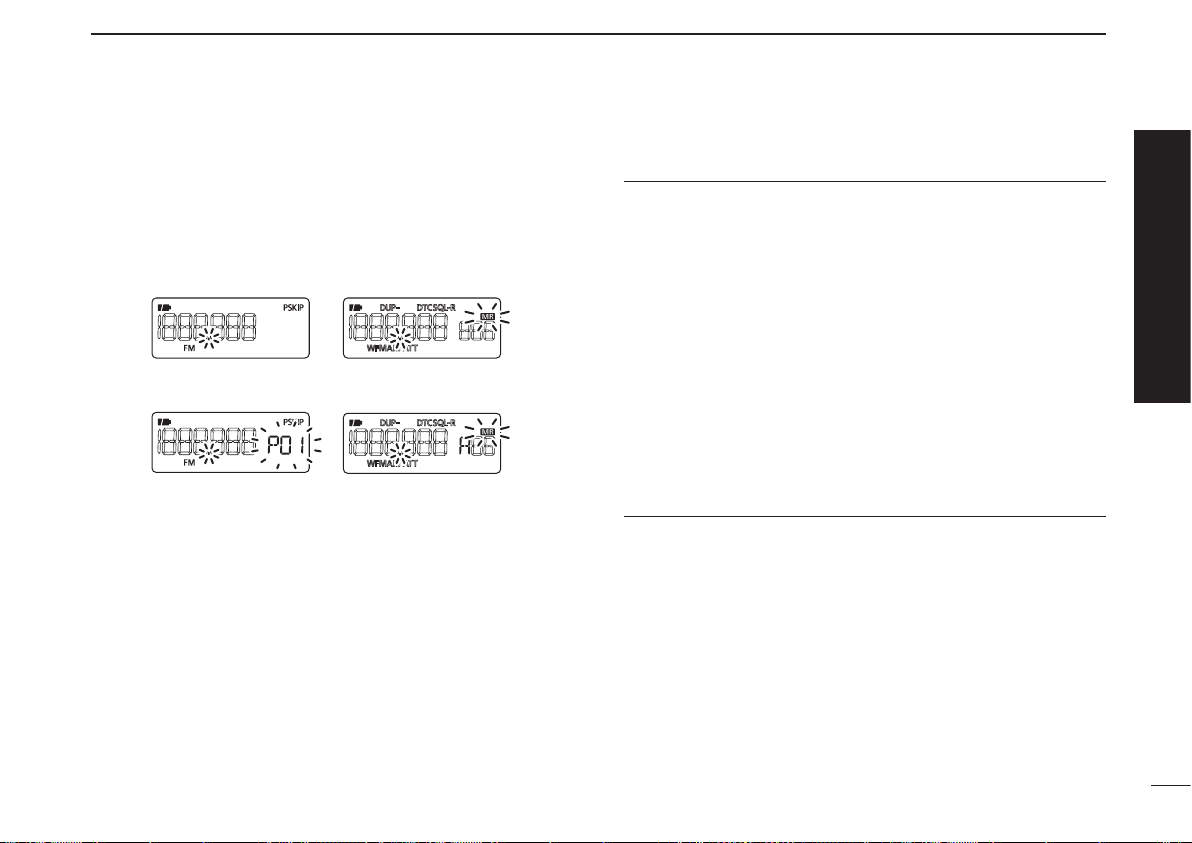
■ Programmed scan operation
25 pairs (50 channels) of scan edge memories, specify the
scanning ranges, are used for programmed scan operation.
The programmed scan scans between the frequencies in
channels “xxA” and “xxB” (xx=00 to 24). Therefore, before
operating the programmed scan, different frequencies must
be programmed into “A” and “B” scan edge channels.
D Programming scan edges
A start frequency must be programmed into a “xxA,” and an
end frequency must be programmed into a “xxB” memory
channel.
1. Setting frequency
In the VFO mode, set a desired receive frequency and
receive mode.
• When the “ ” icon is displayed, push [V/M] to select the VFO
mode.
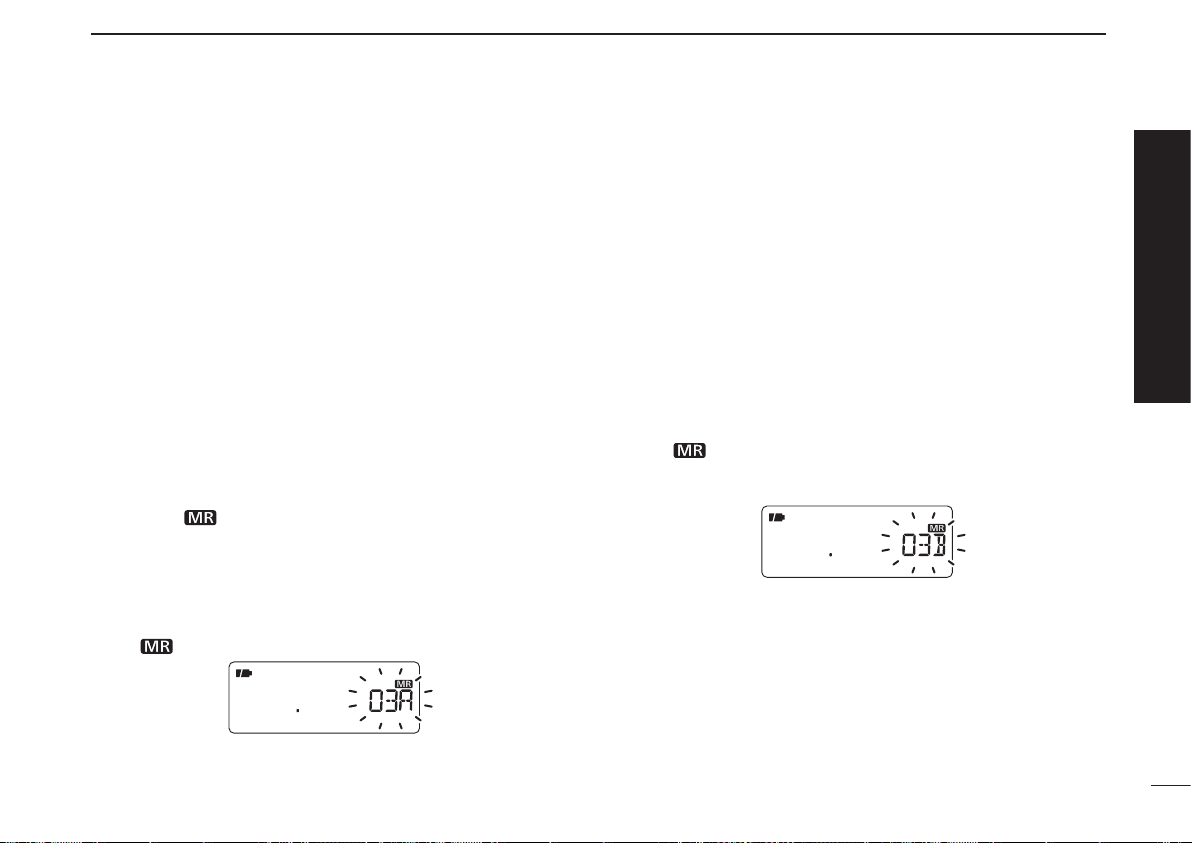
2. Selecting a scan edge “A” channel
Hold down
[S.MW](V/M)
for 1 second,
then rotate [DIAL] to
select one of the 25 scan edge “A” channels.
• The “ ” icon and scan edge channel number blink.
3. Writing a scan edge channel
Hold down [S.MW](V/M) for 1 second until 3 beeps sound.
• The paired scan edge “B” channel is automatically selected if you
continue to hold down [S.MW](V/M) after programming.
• When programming is completed, return to the VFO mode.
4. Setting frequency
In the VFO mode, set a desired receive frequency.
5. Selecting a scan edge “B” channel
Hold down
[S.MW](V/M)
for 1 second,
then rotate [DIAL] to
select one of the 25 scan edge “B” channels.
• The “ ” icon and the scan edge channel number blink.
• When the scan edge “B” channel is already selected in step 3, (by
holding down [S.MW](V/M) after programming), skip this step.
6. Writing a scan edge channel
Hold down [S.MW](V/M) for 1 second until 3 beeps sound.
• The next scan edge “A” channel is automatically selected if you
continue to hold down [S.MW](V/M) after programming.
• When programming is completed, return to the VFO mode.
Quick reference guide
VI
QUICK REFERENCE GUIDE
D Starting scan
1. Select the VFO mode.
Push [V/M] to select the VFO mode for a VFO scan opera-
tion, such as full scan, band scan and programmed scan.
• Select the memory mode by pushing [V/M] again for a memory
scan operation, such as all memory scan, bank link scan or bank
scan.
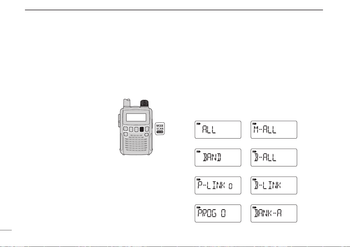
2. Selecting a scan type
Ho ld down
[SC AN](MOD E) for
1 second, and
then rotate [DIAL]
to select one of the desired scan-
ning types.
• Se lect “ALL” for full scan, “BAND ”
for band scan , “P-LINK x” for pro-
gr a m m ed l ink scan (x = 0 t o 9) ,
“P ROG xx” fo r pro gra mme d sca n
(xx= 0 to 24; only programmed scan
edge numbers are displayed).
• Select “M-ALL” for all memory scan,
“B-ALL” for all bank scan, “B-LINK”
for bank link scan or “BANK-x” for
bank scan (x= A to R, T, U, W, Y; only
programmed bank groups are dis-
played).
• Full scan
• Band scan
• Program link scan
• Program scan
• All memory scan
• All bank scan
• Bank link scan
• Bank scan
Scan type display examples
In the VFO mode In the memory mode
VII
QUICK REFERENCE GUIDE
3. Starting scan
Push
[SCAN](MODE)
to start the scan.
• Rotate [DIAL] to change the scanning direction.
• Full/Band scan
• Program link
Program scan
• All memory/All bank
bank link scan
• Bank scan
In the VFO mode In the memory mode
4. Cancelling scan
Push
[SCAN](MODE)
again to stop the scan.
✔ For your information
The memory channel number you program the scan edges
into correlates “PROGxx” as follows:
00A/00B: Selects “PROG 00” to scan between frequencies
programmed in channels 00A and 00B.
01A/01B: Selects “PROG 01” to scan between frequencies
programmed in channels 01A and 01B.
•
•
•
•
23A/23B: Selects “PROG 23” to scan between frequencies
programmed in channels 23A and 23B.
24A/24B: Selects “PROG 24” to scan between frequencies
programmed in channels 24A and 24B.
Quick reference guide
1
PANEL DESCRIPTION
1
!2
!0
u
t
r
e
w
!1
q
Function display
(pp 3, 4)
Speaker
o
i
y
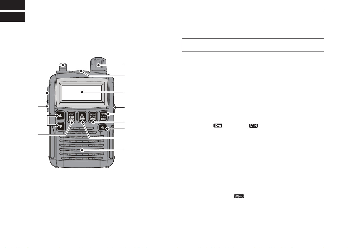
q ANTENNA CONNECTOR (p. I)
Connect the supplied antenna.
• An optional AD-92SMA is available for connecting an antenna
with a BNC connector.
w FUNCTION KEY [FUNC]
While holding down this switch, access a key’s secondary
or third function.
e SQUELCH • ATTENUATOR KEY [SQL] • [ATT](SQL)
➥ Hold down to temporarily open the squelch and moni-
tor the operating frequency. (p. 15)
➥ While holding down this switch, rotate [DIAL]* to adjust
the squelch level. (p. 14)
➥ While holding down [FUNC], push to toggle the attenu-
ator function ON or OFF. (p. 15)
r UP/DOWN KEYS [p]/[q]*
Adjusts the audio volume level. (p. 13)
t BAND • LOCK • MEMORY NAME KEY
[BAND] • [ ](BAND) • [ ](BAND)
➥ Push to select the operating frequency band. (p. 9)
➥ Whi l e h o lding dow n [ F U NC], push and hol d for
1 second to toggle the lock function ON or OFF. (p. 12)
➥ During memory mode operation, hold down [FUNC],
then push this key to select the display type.
• The display shows the memory bank name
†
, memory name
†
and channel number in sequence, and then returns to the
frequency display. (
†
The memory bank name or memory
name must have preprogrammed.)
y TUNING STEP • SET • DIAL EXCHANGE KEY
[TS] • [SET](TS) • [ ](TS)
➥ Push to enter the tuning step selecting mode. (p. 11)
➥ Hold down for 1 second to enter the Set mode. (p. 45)
➥ While holding down [FUNC], push to exchange the
[DIAL] and [p]/[q] keys’ functions. (p. 58)
* The functions of [DIAL] and [p]/[q] can be exchanged.
See page 58 for details.
■ Front, top and side panels

2
1
PANEL DESCRIPTION
1
2
3
4
5
6
7
8
9
10
11
12
13
14
15
16
u POWER KEY [ ]
Hold down for 1 second to turn the receiver power ON or
OFF.
i MODE • SCAN • TONE SCAN KEY
[MODE] • [SCAN](MODE) • [ ](MODE)
➥ Push to select the receive mode. (p. 14)
➥ Hold down for 1 second to enter the scan type selec-
tion mode. (pp. 29, 33)
• Push again to start the scan.
➥ While holding down [FUNC], push to start a tone scan.
(p. 44)
o VFO/MEMORY • MEMORY WRITE • SKIP KEY
[V/M] • [S.MW](V/M) • [ ](V/M)
➥ Toggles between the VFO and the memory mode. (p. 9)
➥ Hold down for 1 second to enter the memory edit
mode. (p. 19)
mWhile in the VFO mode (p. 29)
Hold down [FUNC], then push this key to set the VFO
skip scan setting ON or OFF.
mWhile in the memory mode (p. 35)
Hold down [FUNC], then push this key to select the
scan skip setting for the selected channel.
!0 EXTERNAL DC-IN CONNECTOR [DC4.5V] (p. 7)
Connect an AC adapter or an optional cigarette lighter
cable for both charging the installed rechargeable battery
and operating. Connectable voltage is from 4.5 V DC to
6.3 V DC.
!1 EXTERNAL SPEAKER CONNECTOR [SP]
Connect an optional earphone or headphones.
The internal speaker will not function when any external
equipment is connected. (See page 79 for a list of avail-
able options.)
!2 CONTROL DIAL [DIAL]*
➥ Rotate to select the operating frequency. (p. 11)
➥ While scanning, changes the sc anning direction.
(pp. 29, 33)
➥ While holding down [SQL], sets the squelch level.
(p. 14)
➥ While holding down [FUNC], sets the operating fre-
quency in 100 kHz, 1 MHz or 10 MHz in the VFO
mode. (pp. 11, 17)
➥ While holding down [FUN C], selects the mem ory
channel in 10 channels steps in the memory mode.
(pp. 12, 18)
➥ While holding down [BAND], selects the frequency
band in the VFO mode. (p. 9)
* The functions of [DIAL] and [p]/[q] can be exchanged.
See page 58 for details.
3
1
PANEL DESCRIPTION
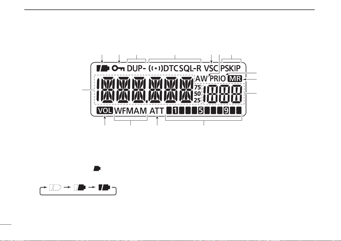
q BATTERY ICON
➥ Both segments appear when the batteries have ample
capacity.
• They do not appear when operating with an external power
source.
➥ Only the right segment “ ” appears when the batter-
ies have less than half capacity.
➥ Scrolls while charging the rechargeable batteries. (p. 8)
➥ Both segments disappear when completely charged.
w LOCK ICON (p. 12)
Appears when the lock function is activated.
e DUPLEX ICONS (p. 16)
“DUP” appears when plus duplex, and “DUP–” appears
when minus duplex operation is selected.
r TONE ICONS (p. 43)
➥ “T SQL” appears while the tone squelch function is in use.
➥ “T SQL-R” appears while the reverse tone squelch
function is in use.
➥ “DTCS” appears while the DTCS squelch function is in
use.
➥ “DTCS” appears while the reverse DTCS squelch func-
tion is in use.
➥ “S” appears with the “T SQL” or “DTCS” icon while
the pocket beep function (with Tone squelch or DTCS
squelch) is in use.
■ Function display
q
!5
!3 !2
o
i
!1
!0
!4
w e yr t u

4
1
PANEL DESCRIPTION
1
t VSC ICON (p. 52)
Appears while the VSC (Voice Squelch Control) function
is in use.
y AUTO WRITE CHANNEL ICON (p. 34)
Appears when an auto write channel is selected.
u SKIP ICONS
mWhile in the VFO mode (p. 29)
“PSKIP” appears when the VFO skip scan setting is
ON.
mWhile in memory mode (p. 35)
➥ “SKIP” appears when the selected memory channel
is specified as a skip channel.
➥ “PSKIP” appears when the displayed frequency is
specified as a skip channel for the memory scan or
skip frequency for the VFO scan.
i PRIORITY WATCH ICON (pp. 39, 40)
Appears while priority watch is in use.
o MEMORY ICON (pp. 9, 18)
Appears when the memory mode is selected.
!0 MEMORY CHANNEL NUMBER
Shows the selected memory channel number. (pp. 9, 18)
!1 SIGNAL STRENGTH INDICATOR (p. 13)
Shows the relative signal strength while receiving signals.
!2 ATTENUATOR ICON (p. 15)
Appears while the RF attenuator is in use.
!3 RECEIVE MODE ICONS (p. 14)
Shows the selected receive mode.
• FM, WFM and AM modes are selectable.
!4 VOLUME EXCHANGE ICON (p. 58)
Appears when the function of [DIAL] and [p ]/[q] are
exchanged.
!5 FREQUENCY READOUT
Shows a variety of information, such as the operating fre-
quency, Set mode contents, memory names.
• The smaller “75,” “50” or “25” to the right of the frequency read-
out shows the 0.75, 0.5 or 0.25 kHz, respectively.
• The decimal point blinks during a scan.
5
BATTERY CHARGING
2
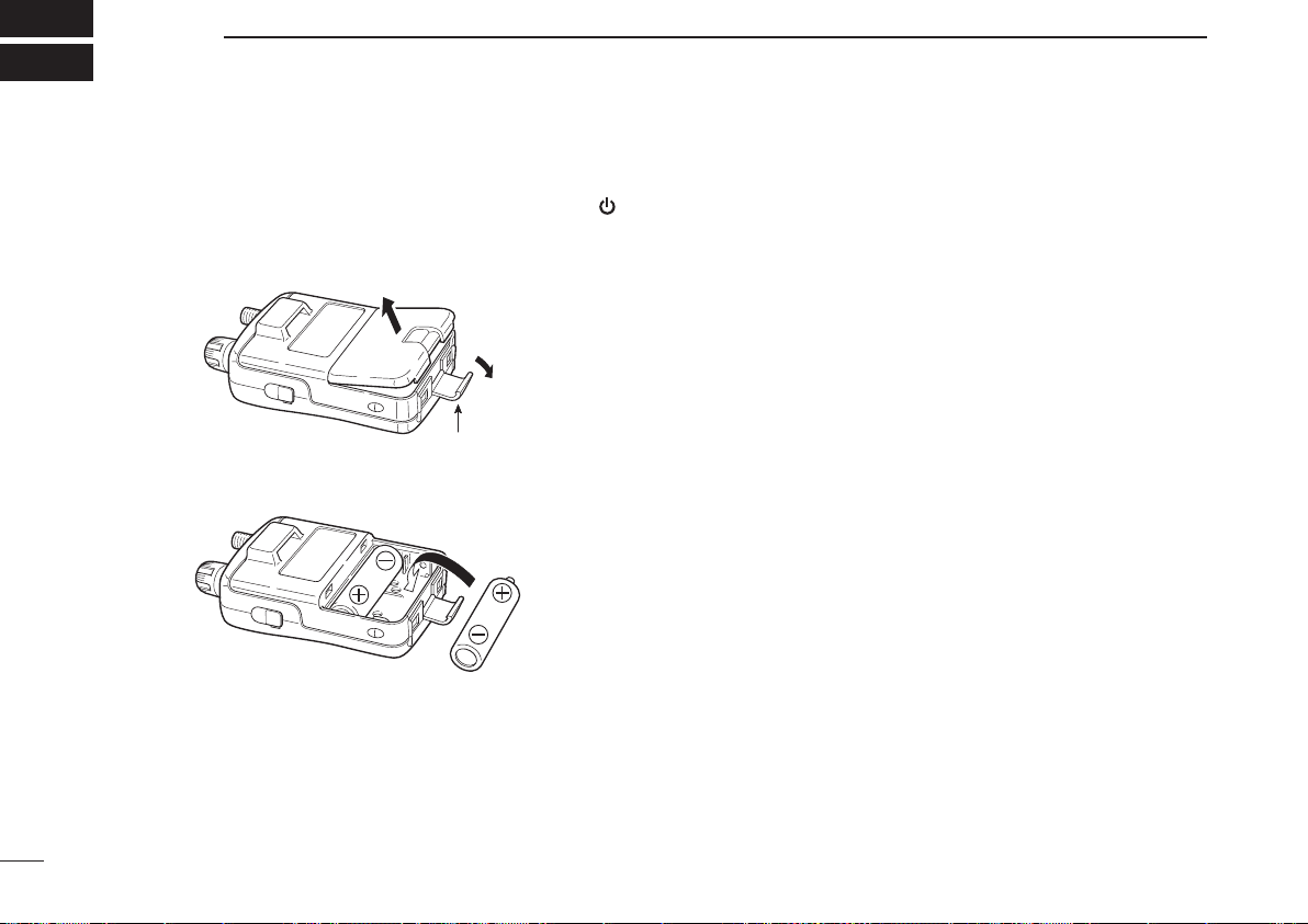
■ Battery installation
Before installing, or replacing the batteries, hold down [ ]
for 1 second to turn the power OFF.
q Remove the battery cover from the receiver.
Latch
w Install two AA (LR6) size Ni-MH batteries.
• Be sure to observe the correct polarity.
■ Caution
• R DANGER! NEVER short the battery terminals (or charg-
ing terminals on the bottom of the receiver). Also, current
may flow into nearby metal objects such as a necklace, so
be careful when placing batteries (or the receiver) in hand-
bags, etc.
Simply carrying with or placing near metal objects such as
a necklace, etc. may cause shorting. This may damage not
only the batteries, but also the receiver.
• R DANGER! NEVER incinerate used batteries. Internal
battery gas may cause an explosion.
• R DANGER! NEVER immerse the batteries in water. If the
batteries become wet, be sure to wipe them dry BEFORE
installing them to the receiver.
• When installing batteries, make sure they are all the same
brand, type and capacity. Also, do not mix new and old bat-
teries together.
• Never use batteries whose insulated covering is damaged.
• Keep battery terminals clean to avoid rust or misscontact.
It’s a good idea to clean battery terminals once a week.
D Caution for the Ni-MH batteries
• CAUTION: Always use the batter ies within the speci-
fied temperature range, –5˚C to +60˚C (+23˚F to +140˚F).
Using the batteries out of their specified temperature range
will reduce the battery’s performance and battery life.

6
2
BATTERY CHARGING
2
• CAUTION: Shorter battery life could occur if the batteries
are left completely discharged, or in an excessive temper-
ature environment (above +55˚C; +131˚F) for an extended
period of time. If the batteries must be left unused for a
long time, they must be detached from the receiver after
charging. Keep them safely in a cool dry place at the fol-
lowing temperature range:
–20˚C to +45˚C (–4˚F to +113˚F) (up to a month)
–20˚C to +35˚C (–4˚F to +95˚F) (up to six months)
–20˚C to +25˚C (–4˚F to +77˚F) (up to a year*)
* We recommend charging the batteries every 6 months.
• If your Ni-MH batteries seem to have no capacity, even
after being charged, completely discharge them by leaving
the power ON overnight. Then, fully charge the batteries
again. If the batteries still do not retain a charge (or only
very little charge), a new batteries must be purchased.
Prior to using the receiver for the first time, the batteries
must be fully charged for optimum life and operation.
• The supplied batteries are rechargeable batteries.
Charge the batteries before first operating the receiver, or
when the batteries become exhausted.
If you want to prolong the battery life, the following points
should be observed:
- Avoid over charging.
- Use the batteries until it becomes almost completely ex-
hausted, under normal conditions.
D Charging caution
• R WARNING! NEVER charge alkaline batteries.
The receiver can charge only the Ni-MH batteries (1.2 V,
1400 mAH typical). Other types of rechargeable battery,
such as Ni-Cd or Li-Ion cannot be charged.
• AVOID over charging— The installed rechargeable batter-
ies can be charged during operation when the AC adapter
or the cigarette lighter cable is connected. To prevent over
charging, the IC-R6 has charging timer that automatically
disconnecting* the charging line electronically after 15 hours
from charging. However, the charging timer will reset and
start charging again when disconnect then reconnecting the
AC adapter or CP-18A/E more than 1 minute interval.
* When the “CHARGE” setting in the Set mode is set to “CHG2 (default),”
the receiver continues to trickle charge after 15 hours have past.
• Recommended temperature range for charging:
between 0°C (+32˚F) and +40°C (+104˚F) by the receiver.
• Use the BC-196SA/SD/BC-153SC AC adapter or CP-18A/
E cigarette liter cable only. NEVER use other manufactur-
ers’ chargers.
• The external DC power supply voltage must be between
12–16 V to charge the batteries and for operation when
using an optional CP-18A/E.
• If t he bat tery ic ons (“ ” and “ ”) disa ppea r only
1 minute after connecting to the DC power supply, the bat-
teries may have problem. In this case, contact your Icom
dealer/distributor, or purchase new batteries.
7
2
BATTERY CHARGING
■ Battery charging
D Charging connections
RWARNING!:
NEVER attempt to charge alkaline batteries.
Receiver
CP-18A/E
Cigarette lighter cable
with DC-DC converter
BC-196SA/SD/BC-153SC
to a cigarette
lighter socket
The shape may
differ, depending
on the version.
to an AC outlet
to the [DC4.5V]
jack
• Charging period: Approx. 15 hours*
* Charging pauses when the receiver’s temperature is out of its
specified temperature range (at that time both batter y icons
blink), then resumes when it returns to the specified range. In
that case, the charging time will be longer than 15 hours.
• External DC power operation becomes possible when
using an AC adapter or cigarette lighter cable. The installed
Ni-MH batteries can also be charged simultaneously.
• CAUTION: BE SURE to disconnect the CP-18A/E from the
cigarette lighter socket when charging is finished, because,
a slight current still flows in the CP-18A/E and will drain the
vehicle’s battery.
D Charging description
When charging the installed batteries at the first time, or
once the batteries are removed for more than 2 seconds, the
following operations are necessary.
q Install Ni-MH batteries. (See page 5.)
w Plug the AC adapter into an AC outlet; or the CP-18A/E
into a cigarette lighter socket.
e Insert the adapter plug into [DC4.5V] of the receiver.
• The battery confirmation is displayed.
If the confirmation does not appear, following operation
is necessary.
q Disconnect the adapter plug from [DC4.5V].
w Holding down [FUNC], insert the adapter plug again.
e Release [FUNC].
NOTE: When no operation is performed for 10 seconds, the
receiver automatically skips these settings, and the receiver
cannot charge the batteries. In that case, remove the bat-
teries for more than 2 seconds and retry these setting from
step q.
8
2
BATTERY CHARGING
1
2
3
4
5
6
7
8
9
10
11
12
13
14
15
16
r Rotate [DIAL] to select “Y,” then push [BAND].
[DIAL]
• The charging confirmation is dis-
played.
t Rotate [DIAL] to select “Y,” then push [BAND] to start the
battery charging.
Rotate
Then, push
• While charging, the icons show “ ,” “ ” and “ (disap-
pears)” in sequence, and “CHARGE” appears when the receiv-
er’s power is OFF. The icons and “CHARGE” disappear when
the battery pack is completely charged.
• It takes approximately 13 hours to fully charge the Ni-MH bat-
teries.
D Charger stand BC-194
The BC-194 can be used as a convenient stand for the
receiver, as well as a charger when used the BC-196SA/SD,
BC-153SC or CP-18A/E as it’s power source.
Receiver
BC-194
CP-18A/E
cigarette lighter
cable
AC adapter
(supplied with receiver)
Double-sided tape*
(supplied with BC-194)
*One sheet supplied. You can cut the desired size.
Cushion sheet
(supplied with
BC-194)
Ground screw and
flat washer
(spplied with
BC-194)
The BC-194 contains a line filter.
If the ground screw is connect ed t o ea rth ground, the
BC-194 will reduce some noises from the power source.
9
FREQUENCY AND CHANNEL SETTING
3
■ VFO and memory channels
The IC-R6 has two normal operating modes: the VFO mode
and the memory mode.
The VFO mode is used for a desired frequency setting
within the frequency coverage.
➥ Push [V/M] to select the VFO mode.
The memory mode is used for quick recall of the prepro-
grammed memory channels.
➥ Push [V/M] to select the memory mode.
• See page 19 for memory programming details.
[DIAL]
“ ” and memory channel
number appear.
• VFO mode display
• Memory mode display
What is VFO?
VFO is an abbreviation of Variable Frequency Oscillator.
Operating frequencies are generated and controlled by the
VFO.
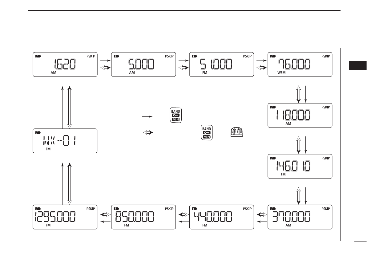
■ Frequency band selection
The receiver can receive the AM broadcast, HF band, 50 MHz,
FM b road cast , VH F air, 144 M Hz, 300 MHz, 40 0 MHz,
800 MHz,* 1200 MHz or Weather channels
†
.
Available frequency bands differ, depending on the ver-
sion. See the specifications for details.
* Some frequency ranges are prohibited in the USA ver-
sion by regulation.
†
Available in only the USA version.
➥ Push [BAND] repeatedly to select a desired frequency
band.
• When the memory mode is selected, push [V/M] to select the
VFO mode first, then push [BAND] to select a desired band.
➥ While holding down [BAND], rotating [DIAL] also selects
the frequency band.
[DIAL]
10
3
FREQUENCY AND CHANNEL SETTING
3
• Available frequency bands
AM broadcast band HF band 50 MHz band
800 MHz band 400 MHz band
FM broadcast band
VHF air band
144 MHz band
300 MHz band
Weather channels*
1200 MHz band
: Push
: While holding down , rotate
The actual frequencies may differ, depending on your receiver version.
*Available in only the USA version
11
3
FREQUENCY AND CHANNEL SETTING
■ Setting a frequency
q Push [V/M] to select the VFO mode, if necessary.
w Select a desired frequency band with [BAND].
• Or, while holding down [BA ND ], rotate [DIAL] to select a
desired frequency band.
e Rotate [DIAL] to select a desired frequency.
• The frequency changes according to the preset tuning step. See
the section to the right for setting the tuning step.
• While holding down [FUNC], rotate [DIAL] to change the fre-
quency in 1 MHz steps (default).
[DIAL]
[DIAL] changes the
frequency according to
the selected tuning step.
While holding down
[FUNC], rotating [DIAL]
changes the frequency
in 1 MHz steps (default).
The MHz tuning step (dial select step) can be set to
100 kHz, 1 MHz or 10 MHz tuning steps in the Set mode.
See page 17 for details.
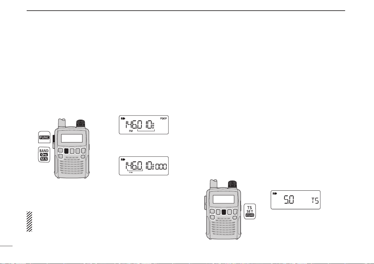
■ Setting a tuning step
The tuning step can be selected for each frequency band.
However, additional steps become selectable in only theadditional steps become selectable in only the
VHF Air band (8.33 kHz) and in the AM broadcast band
(9 kHz). The following tuning steps are available for theThe following tuning steps are available for the
IC-R6.
• 5.0 kHz • 6.25 kHz • 8.33 kHz • 9.0 kHz
• 10.0 kHz • 12.5 kHz • 15.0 kHz • 20.0 kHz
• 25.0 kHz • 30.0 kHz • 50.0 kHz • 100.0 kHz
• 125.0 kHz • 200.0 kHz
D Tuning step selection
q Push [V/M] to select the VFO mode, if necessary.
w Push [BAND] to select a desired frequency band.
• Or, while holding down [BA ND ], rotate [DIAL] to select a
desired frequency band.
e Push [TS] to enter the tuning step selecting mode.
r Rotate [DIAL] to select a desired tuning step.
t Push [TS] to return to the VFO mode.
[DIAL]
5 kHz tuning step
12
3
FREQUENCY AND CHANNEL SETTING
3
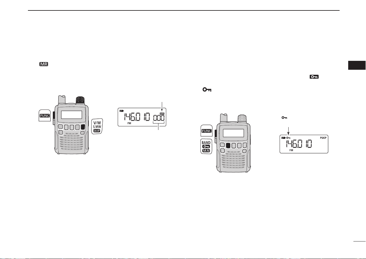
■ Selecting a memory channel
q Push [V/M] to select the memory mode.
• “ ” appears when the memory mode is selected.
w Rotate [DIAL] to select a desired memory channel.
• Only programmed memory channels can be selected.
• While holding down [FUNC], rotate [DIAL] to select a memory
channel in 10 channel steps.
[DIAL]
[DIAL] changes the
memory channel.
Appears
■ Lock function
To prevent accidental frequency changes and unnecessary
function access, use the lock function.
➥ While holding down [FUNC], push and hold [ ](BAND)
for 1 second to turn the lock function ON or OFF.
• “ ” appears while the lock function is activated.
• [SQL] and [p]/[q] can be used while the lock function is in use
with default setting. Either or both [SQL] and [p]/[q] keys can
also be locked in the Set mode. (p. 49)
“ ” appears while the
lock function is in use.
13
BASIC OPERATION
4
■ Receiving
Make sure charged Ni-MH or brand new alkaline batteries
are installed. (p. 7)
q Hold down [ ] for 1 second to turn power ON.
w Push
[p]
or
[q]
to set a desired audio level.
• The function display shows the volume level while setting. See
the section to the right for details.
e Set the receive frequency. (p. 11)
r Set the squelch level. (p. 14)
• While holding down [SQL], rotate [DIAL].
• The first click of [DIAL] indicates the current squelch level.
• “LEVEL 1” is loose squelch and “LEVEL 9” is tight squelch.
• “AUTO” indicates automatic level adjustment using a noise
pulse count system.
• Hold down [SQL] to open the squelch manually.
t When a signal is received:
• The squelch opens and audio is heard.
• The S-meter shows the relative signal strength.
q Power ON
[ ]
e Set frequency
r Set squelch level
w Set audio level
e Select band
r Push for setting
the squelch
(Push to monitor)
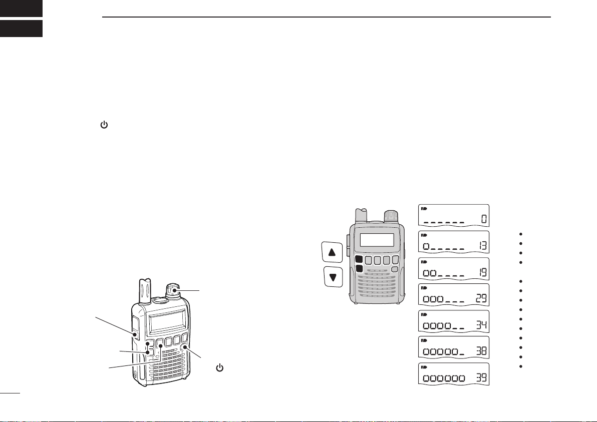
■ Setting audio volume
The audio level can be adjusted through 40 levels.
➥ P
ush [p] or [q] to adjust the audio level.
• A beep tone sounds while adjusting. The tone sound lets you
know the approximate sound level.
• Holding down either key will continuously change the audio
level.
• Holding down [p ] or [q], then rotating [DIAL] will also adjust
the audio level.
• The display shows the volume level while setting.
AUDIO LEVEL
Minimum level
(no audio)
Maximum level
Initial setting
DISPLAY
14
4
BASIC OPERATION
4
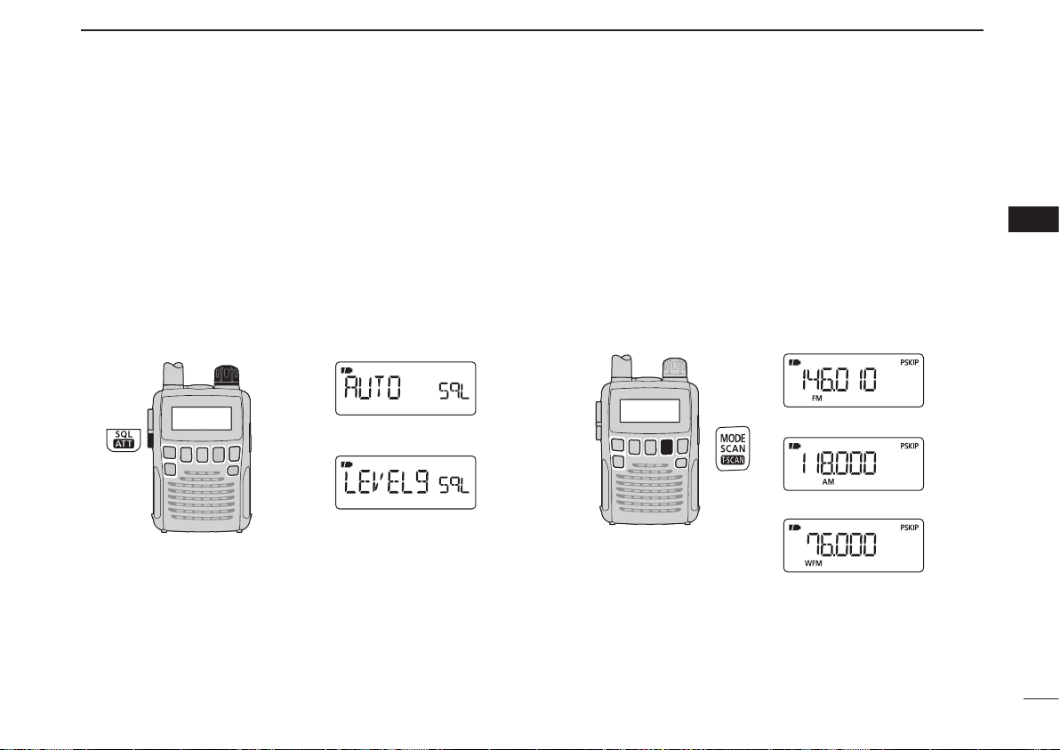
■ Squelch level setting
The squelch circuit mutes the received audio signal, depend-
ing on the signal strength. The receiver has 9 squelch levels,
a continuously open setting and an automatic setting.
➥ While holding down [SQL], rotate [DIAL] to select the
squelch level.
• “LEVEL 1” is loose squelch (for weak signals) and “LEVEL 9” is
tight squelch (for strong signals).
• “AUTO” indicates the automatic level adjustment using a noise
pulse count system.
• “OPEN” indicates the continuously open setting.
[DIAL]
Automatic squelch
Maximum level
■ Receive mode selection
The receiver has three receive modes, FM, AM and WFM.
The mode selection is independently stored in each band
and memory channels.
Typically, the AM mode is used for the AM broadcast stations
(0.495–1.620 MHz) and air band (118–135.995 MHz), and
WFM is used for FM broadcast stations (76–107.9 MHz).
➥ Push [MODE] repeatedly to select a desired receive
mode.
FM mode
AM mode
WFM mode
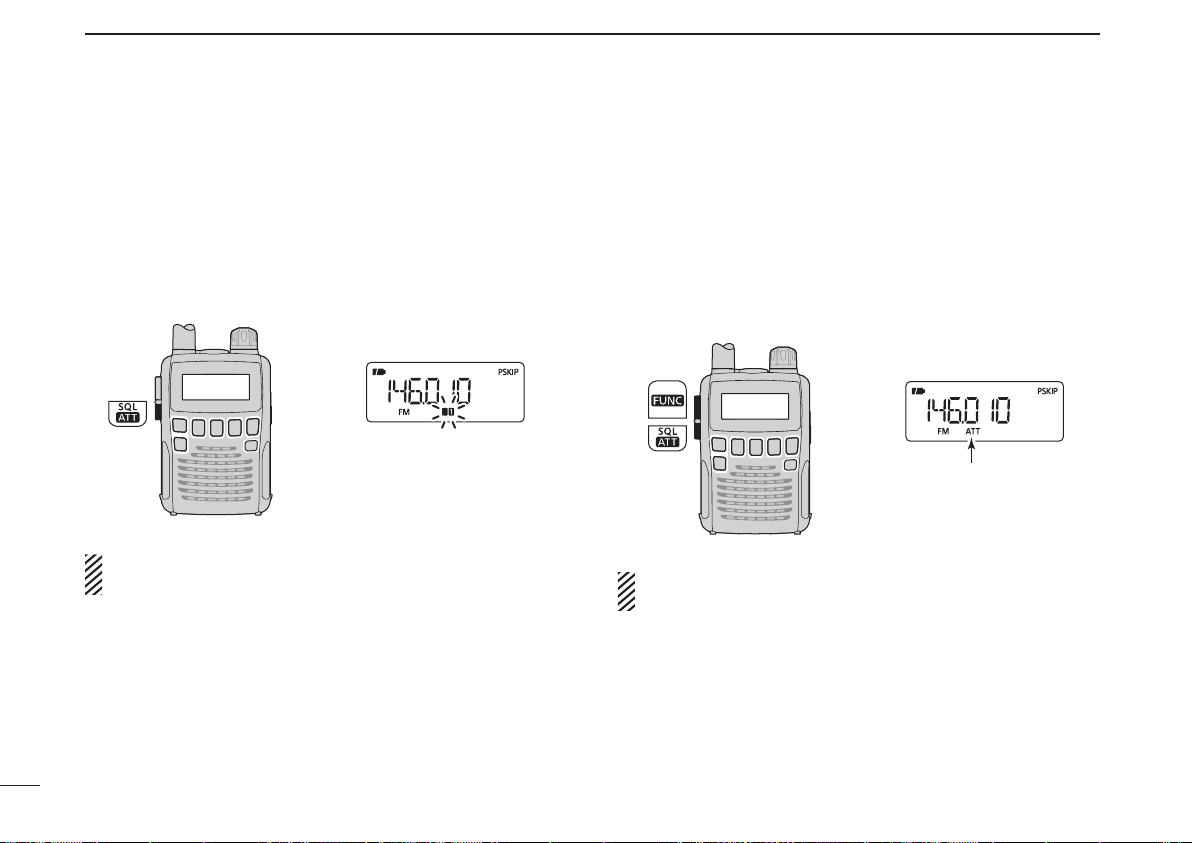
■ Monitor function
This function is used to listen to weak signals, without dis-
turbing the squelch setting. It can also be used to open the
squelch manually, even when mute functions such as the
tone squelch are in use.
➥ Hold down [SQL] to monitor the receive frequency.
The 1st/2nd segments blink
The [SQL] switch can be set to a ‘sticky’ operation in the
Expand set mode. See page 49 for details.
■ Attenuator function
The attenuator prevents a received signal from distor ting
when very strong signals are near a desired frequency, or
when very strong electric fields, such as from a broadcasting
station, are near your location.
➥
While holding down [FUNC], push [ATT](SQL) to turn the
attenuator function ON or OFF.
“ATT” appears while the
attenuator functions is in
use.
When the signal is received by the bar antenna, this func-
tion is not effective.
15
4
BASIC OPERATION
16
4
BASIC OPERATION
4
Duplex communication uses two different frequencies for
transmitting and receiving. Generally, duplex is used in com-
munication through a repeater, some utility communications,
etc.
During duplex operation, the transmit station frequency is
shifted from the receive station frequency by the frequency
offset. Repeater information (frequency offset and shift di-
rection) can be programmed into memory channels. (p. 19)
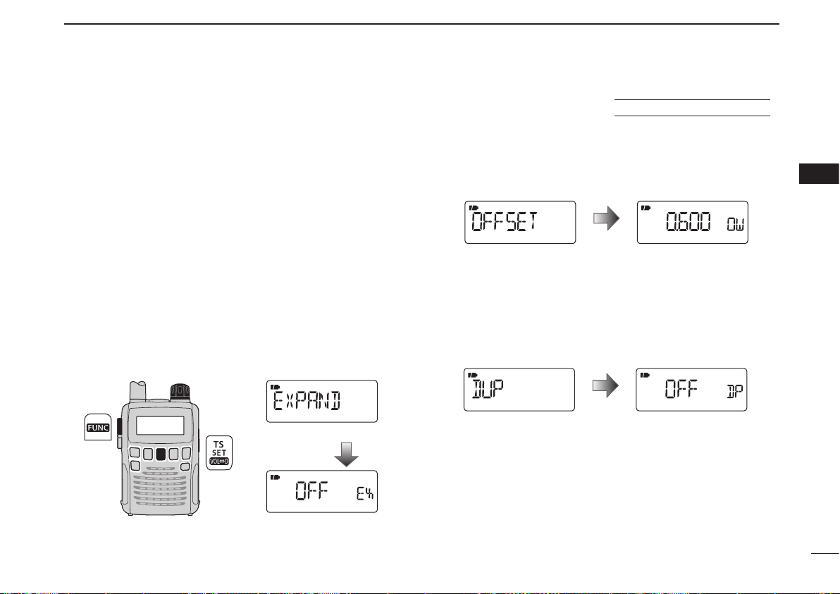
D Setting
q
Set the station’s receive frequency (repeater output frequen-
cy).
w Hold down [SET](TS) for 1 second to enter the Set mode.
e Rotate [DIAL] to select the “EXPAND” item.
• “EXPAND” disappears after 1 second and “OFF” (default) and
“EX” appear.
[DIAL]
Expand set mode item
After 1 sec.
Setting display
r While holding down [FUNC], rotate [DIAL] to select “ON.”
t Rotate [DIAL] to select the “OFFSET” item.
• “OFFSET” disappears after 1 second and “0.600” (default) and
“OW” appear.
(Default offset diffe rs depending on the frequency band or
receiver version.)
Frequency offset item Setting display
After 1 sec.
y While holding down [FUNC], rotate [DIAL] to set a desired
frequency offset within 0.000–159.995 MHz range.
• The tuning step, selected in the VFO mode, is used for setting.
u Rotate [DIAL] to select the “DUP” item.
• “DUP” disappears after 1 second and “OFF” (default) and “DP”
appear.
Duplex item Setting display
After 1 sec.
i While ho lding down [FU NC], rotate [DIAL] to select
“–DUP” or “+DUP.”
o Push [SET](TS) to exit the Set mode.
!0 Hold down [SQL] to directly monitor the station’s transmit
frequency (repeater input frequency).
■ Duplex operation
using EXPAND SET MODE
 Loading...