


INSTRUCTION MANUAL
DUAL BAND FM TRANSCEIVER
iC-w32a iC-w32e
This device complies with Part 15 of the FCC rules. Operation is subject to the following two conditions: (1) This device may not cause harmful interference, and (2) this device must accept any interference received, including interference that may cause undesired operation.

IMPORTANT
READ ALL INSTRUCTIONS carefully and com-
pletely before using the transceiver.
SAVE THIS INSTRUCTION MANUAL — This
instruction manual contains important operating instructions for the IC-W32A and IC-W32E.
EXPLICIT DEFINITIONS
The explicit definitions below apply to this instruction manual.
WORD |
DEFINITION |
|
RWARNING |
Personal injury, fire hazard or electric shock |
|
may occur. |
||
|
|
|
CAUTION |
Equipment damage may occur. |
|
NOTE |
If disregarded, inconvenience only. No risk |
|
of personal injury, fire or electric shock. |
||
|
||
|
|
The IC-W32E complies with the essential requirements of the 89/336/EEC directive for Electromagnetic Compatibility. This compliance is based on conformity with the ETSI specification prETS300 684 (EMC product standard for Commercially Available Amateur Radio Equipment).
CAUTIONS
RWARNING! NEVER hold the transceiver so that the antenna is very close to, or touching exposed parts of the body, especially the face or eyes, while transmitting. The transceiver will perform best if the microphone is 5 to 10 cm (2 to 4 in) away from the lips and the transceiver is vertical.
RWARNING! NEVER operate the transceiver with a headset or other audio accessories at high volume levels. Hearing experts advise against continuous high volume operation. If you experience a ringing in your ears, reduce the volume level or discontinue use.
NEVER connect the transceiver to an AC outlet or to a power source of more than 16 V DC. Such a connection will damage the transceiver.
NEVER connect the transceiver to a power source that is DC fused at more than 5 A. Accidental reverse connection will be protected by this fuse, higher fuse values will not give any protection against such accidents and the transceiver will be ruined.
NEVER attempt to charge alkaline or dry cell batteries. Beware that external DC power connections will charge batteries inside the battery case. This will damage not only the battery case but also the transceiver.
i
DO NOT push the PTT when not actually desiring to transmit.
DO NOT allow children to play with any radio equipment containing a transmitter.
DO NOT operate the transceiver near unshielded electrical blasting caps or in an explosive atmosphere.
AVOID using or placing the transceiver in direct sunlight or in areas with temperatures below –10°C (+14°F) or above +60°C (+140°F).
The use of non-Icom battery packs/chargers may impair transceiver performance and invalidate the warranty.
Even when the transceiver power is OFF, a slight current still flows in the circuits. Remove the battery pack or case from the transceiver when not using it for a long time. Otherwise, the battery pack or installed dry cell batteries will become exhausted.
UNPACKING |
|
|
|
|
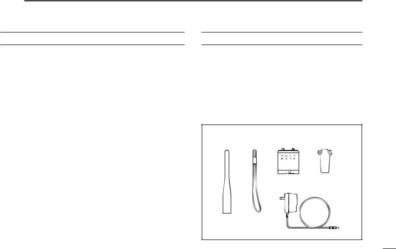
Accessories included with the transceiver: |
|
Qty. |
||
q Antenna ......................................................................... |
|
|
|
1 |
w Handstrap ...................................................................... |
|
|
|
1 |
e Battery pack (BP-173 or BP-180) or |
|
|
||
battery case (BP-170) attached to the transceiver |
........ 1 |
|||
r Belt clip .......................................................................... |
|
|
|
1 |
t Wall charger* ................................................................. |
|
|
|
1 |
* Not supplied for some versions. |
|
|
||
q |
w |
e |
r |
|
t
Antenna for U.S.A. version differs from that shown above.
ii

TABLE OF CONTENTS
IMPORTANT .............................................. |
i |
4 |
BASIC OPERATION .................. |
17 – 18 |
9 |
SUBAUDIBLE TONE OPERATION . 32 – 33 |
||
EXPLICIT DEFINITIONS ........................... |
i |
|
■Receive and transmit ...................... |
17 |
|
■Tone squelch operation .................. |
32 |
|
CAUTIONS ................................................. |
i |
5 |
REPEATER OPERATION |
19 – 21 |
|
■Tone scan ....................................... |
33 |
|
UNPACKING ............................................. |
ii |
|
■Pocket beep operation .................... |
33 |
||||
TABLE OF CONTENTS ............................ |
iii |
|
■General .......................................... |
19 |
10 |
OTHER FUNCTIONS |
34 – 38 |
|
1 |
PANEL DESCRIPTION |
1 – 7 |
|
■Subaudible tones ........................... |
20 |
|||
|
■Offset frequency ............................. |
20 |
|
■Guide function ................................ |
34 |
|||
|
■Switches, controls, keys and |
|
|
■Auto repeater function .................... |
21 |
|
■Battery voltage indication ............... |
34 |
|
connectors ....................................... |
1 |
6 |
MEMORY/CALL PROGRAMMING . 22 – 25 |
|
■Auto power-off function ................... |
35 |
|
|
■Function display ............................... |
6 |
|
■Function display backlighting ......... |
35 |
|||
2 |
BATTERY PACKS AND |
|
|
■General .......................................... |
22 |
|
■Power saver ................................... |
36 |
|
|
■Programming during selection ........ |
22 |
|
■LCD contrast .................................. |
36 |
||
|
ACCESSORIES ........................... |
8 – 11 |
|
■Programming after selection .......... |
23 |
|
■Optional HM-75A functions ............ |
37 |
|
■Battery pack charging ...................... |
8 |
|
■Memory edit (transferring) .............. |
23 |
|
■Handheld-to-handheld cloning ....... |
38 |
|
■Charging precautions ....................... |
8 |
|
■Memory names .............................. |
24 |
|
■Partial reset .................................... |
38 |
|
■About the battery pack ...................... |
8 |
|
■Memory clear ................................. |
25 |
|
■All reset .......................................... |
38 |
|
■Charging connections ...................... |
9 |
7 |
DTMF MEMORY |
26 – 27 |
11 |
TROUBLESHOOTING |
39 |
|
■Battery case ................................... |
10 |
||||||
|
■Accessory attachment .................... |
11 |
|
■Programming a DTMF code ........... |
26 |
12 |
MODE ARRANGEMENT |
40 – 41 |
3 |
FREQUENCY AND CHANNEL |
|
|
■Transmitting a DTMF code ............. |
27 |
|||
|
|
■DTMF transmission speed ............. |
27 |
|
|
|
||
|
SETTING ................................... |
12 – 16 |
8 |
SCAN OPERATION |
28 – 31 |
13 |
SPECIFICATIONS ............................ |
42 |
|
■Power ON ....................................... |
12 |
14 |
OPTIONS |
43 |
|||
|
■VFO and memory/call channels |
..... 12 |
|
■Scan types ..................................... |
28 |
|||
|
■Main band selection ....................... |
13 |
|
■Full/programmed scan ................... |
29 |
|
|
|
|
■Operating band selection ............... |
13 |
|
■Memory scan ................................. |
29 |
|
|
|
|
■Frequency or channel selection |
|
|
■Skip channel setting ....................... |
30 |
|
|
|
|
via the keypad ................................ |
14 |
|
■Scan resume condition ................... |
30 |
|
|
|
|
■Using the tuning dial ....................... |
15 |
|
■Frequency skip function ................. |
31 |
|
|
|
|
■Lock function .................................. |
15 |
|
|
|
|
|
|
|
■Setting tuning dial increments ........ |
16 |
|
|
|
|
|
|
iii

PANEL DESCRIPTION 1 
■ Switches, controls, keys and connectors
q @5 @4
qAntenna connector
w [POWER] 
@3[DIAL] |
DC13.5V |
|
|
– |
|
|
|
+ |
|
|
|
|
|
SP |
MIC |
@2[VOL] |
|
DIAL |
@3 |
|
|
|
|
|
|
VOL |
|
e [SQL] |
|
|
r [PTT] |
@1[TX/RX] |
|
|
||
t [L/G] |
@0Speaker/ |
|
y [MAIN] |
microphone |
|
!9Battery pack |
||
u [BAND] |
release |
|
i [MR] |
!8[CALL] |
|
!7[S.MW] |
||
o [VFO] |
||
|
||
|
!6[H/L] |
|
|
!5[TONE] |
|
|
!4 |
|
|
!3[M•N] |
|
|
!2 |
|
|
!1DIGIT KEYS |
|
|
!0[.] |
|
SCAN DT |
|
|
|
|
|
|
M |
|
|
|
|
|
y |
F |
|
|
|
|
|
MAIN |
|
|
|
|
|
|
|
CHNG |
|
|
|
|
|
u |
BAND |
i |
!8 |
|
|
|
|
|
|
|
|
||
|
CLR MHz |
SKIP |
LOCK |
|
MW |
|
o |
VFO |
MR |
CALL |
|
S.MW |
!7 |
|
QZ |
ABC |
DEF |
|
SET J |
|
|
1 |
2 |
3 |
A |
H/L |
!6 |
|
GHI |
JKL |
MNO |
|
DUP K |
|
!1 |
4 |
5 |
6 |
B |
TONE |
!5 |
|
PRS |
TUV |
WXY |
|
|
|
|
7 |
8 |
9 |
C |
|
!4 |
|
DTMF•M |
Symbol |
T SCAN |
|
MN•W |
|
|
• |
0 |
|
D |
M•N |
!3 |
M#
!0 !2
1

1 PANEL DESCRIPTION
qANTENNA CONNECTOR (p. 11) Connects the supplied antenna.
w POWER SWITCH [POWER] (p. 12)
Push and hold for 2 sec. to toggle the transceiver power ON and OFF.
e SQUELCH SWITCH [SQL] (p. 17)
Push to open the main band’s squelch and monitors the operating frequency.
Set the squelch level while pushing this key and rotating the tuning dial.
r PTT SWITCH [PTT] (p. 17)
Push and hold to transmit; release to receive.
tLIGHT/GUIDE SWITCH [L/G]
Activates the display and keypad backlighting for 5 sec.
•The backlighting can be set as manual ON/OFF, automatic
ON/OFF and automatic OFF with 5 sec. timer (default) using initial set mode. (p. 35)
Shows a quick description of a key’s function when pushing this key and the desired key. (p. 34)
•In set mode, the quick description automatically appears when pausing an operation for 5 sec.
y MAIN KEY [MAIN (SCAN) (DTMF)]
SCAN DT
M
F
MAIN
Push to toggle the main band assignment. (p. 13)
Starts and stops a scan when pushed for 2 sec. (p. 29)
While pushing [PTT], this key transmits the selected DTMF memory contents. (p. 26)
u BAND KEY [BAND (CHNG)]
CHNG Push to select the operating band (VHF, UHF,
BAND |
etc.) or deactivation. (p. 13) |
|
•For VHF display, 144 MHz band, 430(440) MHz band, avionics band*1 and weather channels*2 can be selected.
*1 U.S.A. and Asia versions only *2 U.S.A. version only
•For UHF display, 144 and 430(440) MHz bands can be selected.
Enters the band arrangement condition to exchange the VHF and UHF displays when pushed at turning power ON. (p. 13)
iMEMORY MODE KEY [MR (SKIP)]
SKIP Push to select memory mode. (p. 22)
MR While in memory mode, push this key for 2 sec. to toggle the selected memory channel between a skip and non-skip channel. (p. 30)
2

o VFO MODE KEY [VFO (CLR) (MHz)]
CLR MHz Push this key to cancel most functions, then push VFO again to select VFO mode. (p. 12)
•When making a mistake during digit input, push this key to cancel and start from the beginning.
Selects 1 MHz tuning step when pushed for 2 sec. in VFO mode. (p. 16)
Partially resets the VFO frequencies, VFO settings and set mode settings when pushed at turning power ON. (p. 38)
!0DECIMAL POINT KEY [ • (DTMF•M) (M)]
DTMF•M In VFO mode, push to enter the operating fre-
•quency from the 100 kHz digit. (p. 14)
MPush this key for 2 sec. to enter DTMF memory mode, then push again for 2 sec. to program the DTMF memory. (p. 26)
While pushing [PTT], this key sends a DTMF “E” (M).
!1DIGIT KEYS
Input the specified digit during frequency input, memory channel selection, etc.
Transmit the DTMF code of the specified digit while pushing [PTT].
PANEL DESCRIPTION 1
For the [1]–[5] and [0] keys, select scan edges during full/ programmed scan.
•Push [1]–[5] to select scan edges “1A/1B”–“5A/5B,” respectively.
•Push [0] to select full scan.
In addition, each key has character input for memory or DTMF memory names (characters are assigned to keys using the same convention as for telephones). (pgs. 24, 26)
!2TONE SCAN KEY [T SCAN (Ω) (#)]
T SCAN Push this key for 2 sec. to start the tone scan. (p. 33)
#While programming memory channels or DTMF memory names, this key moves the cursor backward.
While pushing [PTT], this key sends a DTMF “F”
(#).
!3MEMORY NAME KEY [M•N (MN•W) (≈)]
MN•W
D M•N
Push to toggle between frequency and name indications. (p. 24)
While programming memory channels or DTMF memory names, this key moves the cursor forward.
While pushing [PTT], this key sends a DTMF “D.”
3

1 PANEL DESCRIPTION
!4C KEY [C]
C |
|
While pushing [PTT], this key sends a DTMF “C.” |
|
|
|
!5TONE/DUPLEX KEY [TONE (DUP) (K)] |
||
|
DUP K Push this switch to activate the following functions |
|
B TONE |
in order (pgs. 19, 32). |
|
|
||
•Subaudible tone encoder—“T” appears.
•Pocket beep—“T SQLS” appears.
•Tone squelch— “T SQL” appears.
•No tone operation— no indicator appears.
Push this key for 2 sec. to select semi-duplex or simplex operation. (p. 19)
•“–DUP” appears during minus duplex operation, “DUP” appears during plus duplex operation and no indicator appears during simplex operation.
While pushing [PTT], this key sends a DTMF “B.”
!6OUTPUT POWER/SET MODE KEY [H/L (SET) (J)]
|
SET J Push this key to toggle between high and low out- |
|
A |
H/L |
put power. (p. 17) |
Push this key for 2 sec. to enter set mode. (p. 41)
Enters initial set mode when pushed at power ON. (p. 41)
While pushing [PTT], this key sends a DTMF “A.”
!7SELECT MEMORY WRITE KEY [S.MW (MW)]
MW Push this key to select the desired memory chan- S.MW nel number to be programmed. (p. 22)
•“M” and memory channel number flash and the [DIAL] can be used for channel selection.
Push this key for 2 sec. to write the displayed frequency and information into the selected memory channel (or VFO, call channel). (p. 22)
Push then push and hold this key while in memory select mode to erase the contents of the selected memory channel. (p. 25)
!8CALL MODE KEY [CALL (LOCK)]
LOCK Push this key to select the call channel. (p. 12) CALL Push this key for 2 sec. to toggle the lock function
ON and OFF. (p. 15)
•“ ”appears while the lock function is activated.
•[POWER], [VOL], [SQL], [PTT], [L/G] and [H/L] can still be accessed while the lock function is ON.
While pushing [PTT], push this key for 1 to 2 sec. to transmit a 1750 Hz tone burst for repeater access. (Eur., U.K. and Italy versions only; p. 19)
!9BATTERY PACK RELEASE (p. 10)
Push to open the latch for battery pack removal.
@0SPEAKER/MICROPHONE
4
@1TX/RX INDICATOR [TX/RX] (p. 17)
Lights green while receiving a signal or when the squelch is open; lights red while transmitting; lights orange during crossband full duplex operation.
@2VOLUME CONTROLS [VOL] (p. 17) Rotate [VOL] to adjust the audio level.
@3TUNING DIALS [DIAL]
Rotate [DIAL] to set operating frequencies, memory channels, set mode contents, etc. (p. 15)
While pushing [SQL], this dial sets the squelch level. (p. 17)
While pushing [BAND], this dial sets the operating band. (p. 13)
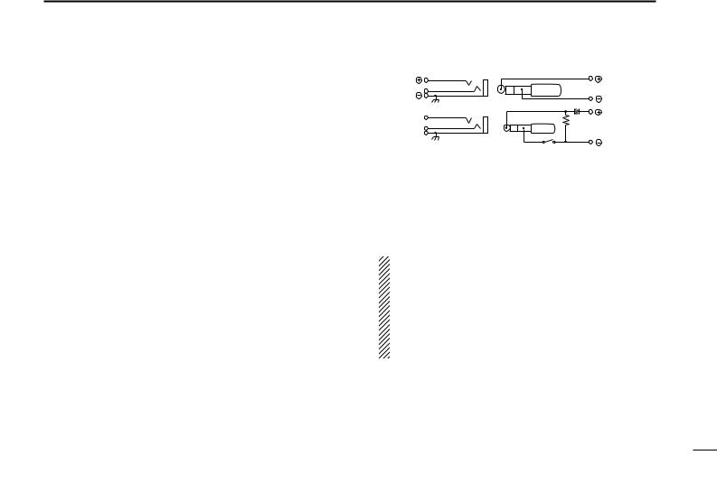
@4EXTERNAL SPEAKER AND MICROPHONE JACKS [SP/MIC]
Connect an optional speaker-microphone or headset, if desired. The internal microphone and speaker will not function when either is connected. (See p. 43 for a list of available options.)
|
PANEL DESCRIPTION 1 |
|
DExternal connection |
|
|
Remote [SP] |
|
Audio out |
|
|
(8 Ω ) |
MIC |
33 kΩ |
Audio input |
[MIC] |
|
|
|
(2 kΩ ) |
|
3.5 V |
|
|
|
|
|
PTT |
|
|
PTT
The above connection does not apply when a condensor microphone is connected.
@5EXTERNAL DC POWER JACK [DC13.5V]
Allows operation with a 13.5 V DC power source using the optional cables, CP-12/L or OPC-254/L.
CAUTION: Operation with an external DC power source simultaneously charges batteries inside the battery case or the battery pack. When using dry cell batteries this may cause battery leakage and damage the transceiver; when using a Ni-Cd battery pack this may cause battery overcharging and shorten the life of the battery pack.
5
1 PANEL DESCRIPTION
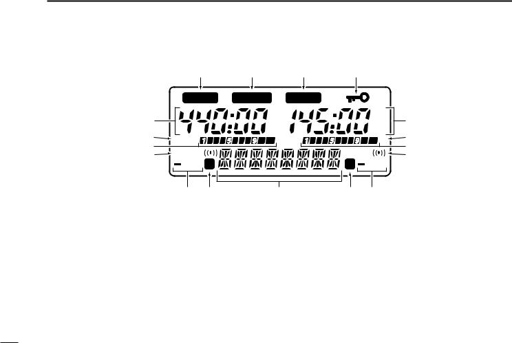
■ Function display
|
q |
|
!0 |
q |
o |
|
|
|
MAIN |
GUIDE |
MAIN |
|
|
|
|
|
|
|
75 |
|
|
75 |
|
w |
|
|
50 |
|
|
50 |
w |
e |
|
|
25 |
|
|
25 |
e |
LOW |
|
LOW |
|
|
|||
r |
|
T SQL |
r |
||||
T SQL |
|
|
|
||||
t |
|
|
|
t |
|||
|
DUP S |
|
|
S |
DUP |
|
|
|
y |
u |
i |
|
u |
y |
|
qMAIN BAND INDICATORS (p. 13)
Appear above the frequency which is selected as the main band.
• Only one of these indicators appears at a time.
wFREQUENCY READOUTS
Show the operating frequency, set mode contents, etc.
•The frequency on the left and right can be exchanged. (p. 13)
•The smaller “75,” “50” and “25” to the right of each readout indicate 7.5, 5.0 and 2.5 kHz, respectively.
•The decimal point of the frequency flashes during scan. (p. 29)
•While operating in the avionics band, a colon appears to indicate AM mode. (U.S.A. and Asia versions only)
6
e LOW POWER INDICATORS (p. 17) Appear when low output power is selected.
r S/RF INDICATORS (p. 17)
Show the relative signal strength while receiving.
Show the output power selection while transmitting.
t TONE INDICATORS (pgs. 19, 32)
“T” appears when the subaudible tone encoder is in use; “T SQLS” appears during pocket beep operation and “T SQL” appears when the tone squelch function is activated.
y DUPLEX INDICATORS (p. 19)
Appear when semi-duplex operation (repeater operation) is in use.
•“–DUP” appears when minus duplex is selected; “DUP” only, appears when plus duplex is selected.
u SKIP INDICATORS
Appear when a selected memory channel is set as a skip channel. (p. 30)
•Skip channels are not detected (ignored) during memory scan.
Flash during full/programmed scan when the frequency skip function is activated. (p. 31)
PANEL DESCRIPTION 1
iALPHANUMERIC READOUT
Shows the selected memory channel number in memory mode.
•Memory name can be selected instead of channel numbers. (p. 24)
Shows guide (or description) when the [L/G] and desired keys are pushed, or no key operation is performed for 5 sec. in set mode, during name programming, etc. (p. 34)
oLOCK INDICATOR (p. 15)
Indicates that the lock function is in use.
!0QUICK GUIDE INDICATOR (p. 34)
Appears when the quick guide function is activated.
7

 2 BATTERY PACKS AND ACCESSORIES
■ Battery pack charging
The supplied* BP-173 or BP-180 BATTERY PACK includes rechargeable Ni-Cd batteries and can be charged approx. 300 times. Charge the battery pack before first operating the transceiver or when the battery pack becomes exhausted.
* Optional for versions which come with the BP-170 BATTERY CASE.
■ About the battery pack
DOperating period
Depending on the attached battery pack, the operating period of the transceiver varies. Refer to p. 43 for battery pack specifications.
If you want to be able to charge the battery pack more than 300 times, the following points should be observed:
1.Avoid overcharging. The charging period should be less than 48 hours.
2.Use the battery until it becomes almost completely exhausted under normal conditions. We recommend battery charging just after transmitting becomes impossible.
■ Charging precautions
NEVER attempt to charge dry cell batteries. This will cause internal liquid leakage and damage the battery case and transceiver.
NEVER connect two or more chargers at the same time.
Charging may not occur under temperatures of 10°C (50°F) or over temperatures of 40°C (104°F).
DBattery pack life
If your battery pack seems to have no capacity even after being fully charged, completely discharge it by leaving the power ON overnight. Then, fully charge the battery pack again.
If the battery pack still does not retain a charge (or very little), a new battery pack must be purchased.
DRecycling information (U.S.A. only)
|
|
|
|
The product that you have purchased contains a |
|
|
|
|
RBRC |
|
B |
R |
C |
rechargeable battery. The battery is recyclable. At |
R |
|
|||
|
|
the end of its life, under various state and local |
||
|
|
|
||
|
|
|
|
|
|
|
|
|
Ni-Cd |
|
|
|
|
laws, it may be illegal to dispose of this battery into |
the municipal waste stream. Call 1-800-8-BATTERY for battery recycling options in your area or contact your dealer.
8
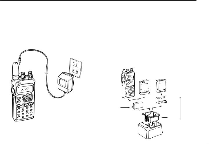
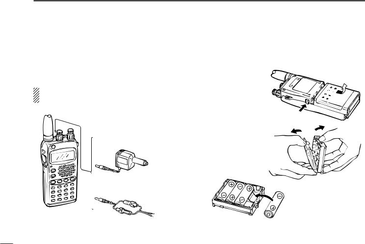
■ Charging connections
DRegular charging
Attach the supplied* or optional battery pack; then, connect the supplied* wall charger via an AC outlet as shown below.
* Optional for versions which include a battery case.
5V]
Wall charger
Charging periods:
15 hours (w/BP-171, BP-173 or BP-180) 20 hours (w/BP-172)
BATTERY PACKS AND ACCESSORIES 2
DRapid charging with the BC-119
qInsert the AD-51A into the charging slot of the BC-119.
•The AD-75 may be additionally necessary if the BC-119 contains no connection terminals.
wInsert the AD-51B into the groove in the AD-51A (front-fac- ing side of the AD-51A) observing the proper orientation.
eInsert the battery pack, either by itself or attached to the transceiver, into the AD-51A.
Any battery |
BP-173 or |
BP-171 or BP-172 |
pack |
||
attached to |
BP-180 |
without transceiver |
transceiver |
|
|
Check orientation |
AD-51B |
Packed |
|
together |
|
for correct |
|
as the |
charging |
|
AD-51 |
|
AD-51A |
(optional) |
|
|
|
Charging periods: |
BC-119 + AD-75 |
|
(optional) |
|
|
1 hour (w/BP-171 or BP-180)
1.5 hours (w/BP-172 or BP-173)
9
2 BATTERY PACKS AND ACCESSORIES
DOperation with an optional cable
Connect an optional charger or cable to the transceiver as illustrated below. Be careful of battery overcharging as the connected battery is charged simultaneously.
CAUTION: Remove dry cell batteries from the BP-170 BAT- TERY CASE when using the [DC13.5V] jack.
5V]
CP-12 (optional)
12 V cigarette lighter socket
OPC-254 (optional)
+
black _
To a 4.5 to 16 V DC power source
■ Battery case
When using a battery case attached to the transceiver, install 4 AA(R6) size alkaline batteries as illustrated below.
Remove the case from the transceiver.
Open the case.
Install 4 AA(R6) size dry cell batteries into the battery case.
10
BATTERY PACKS AND ACCESSORIES 2
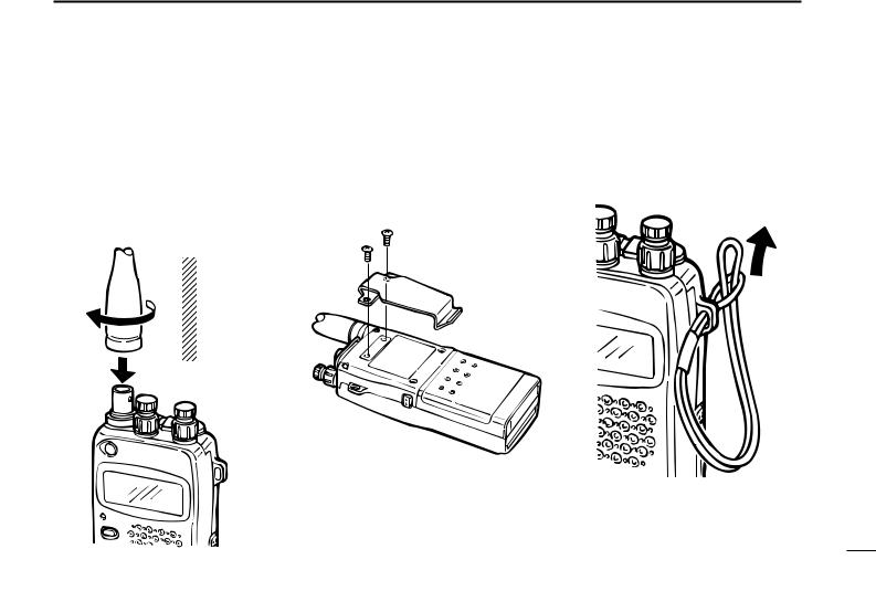
■ Accessory attachment
DAntenna
Insert the supplied antenna into the antenna connector and rotate the antenna as shown in the diagram below.
Keep the jack cover attached when jacks are not in use to avoid bad contacts.
CAUTION:
Transmitting without the antenna may damage the transceiver.
DBelt clip
Remove screws, then attach the belt clip using the same screws. Conveniently attaches to your belt.
DHandstrap
Attach the handstrap as shown in the diagram below. Facilitates carrying.
11
 Loading...