


Icom IC-F9023T, IC-F9023S, IC-F9023B, IC-F9021S, IC-F9011S User Manual
...INSTRUCTION MANUAL
VHF P25 TRUNKING
HANDHELD TRANSCEIVERS
iF9011series
UHF P25 TRUNKING HANDHELD TRANSCEIVERS
iF9021series iF9023series
The photo shows the 10-key type VHF transceiver.

IMPORTANT
READ ALL INSTRUCTIONS carefully and com-
pletely before using the transceiver.
SAVE THIS INSTRUCTION MANUAL — This
instruction manual contains important operating instructions for the IC-F9011B/IC-F9011S/IC-F9011T VHF P25 TRUNKING HANDHELD TRANSCEIVERS and the IC-F9021B/IC-
F9021S/IC-F9021T, IC-F9023B/IC-F9023S/IC-F9023T UHF P25 TRUNKING HANDHELD TRANSCEIVERS.
When the optional UT-125 unit is installed:
When you attempt to re-export this product and/or AES encryption of this product is activated, you must comply with the export regulations of your country, which can be highly restrictive. YOUR FAILURE TO COMPLY WITH EXPORT REGULATIONS MAY SUBJECT YOU TO FINES OR PENALTIES. AES encryption products including this software fall under the control of the Japanese Government as described in Appendix I: Export Legal Controls and Appendix: Exchange Legal Controls. Please consult with your dealer or sales representative for details.
Icom, Icom Inc. and the Icom logo are registered trademarks of Icom Incorporated (Japan) in Japan, the United States, the United Kingdom, Germany, France, Spain, Russia, Australia, New Zealand, and/or other countries.
All other products or brands are registered trademarks or trademarks of their respective holders.
i
EXPLICIT DEFINITIONS
WORD |
DEFINITION |
|
RDANGER! |
Personal death, serious injury or an explo- |
|
sion may occur. |
||
|
||
RWARNING! |
Personal injury, fire hazard or electric |
|
shock may occur. |
||
|
||
CAUTION |
Equipment damage may occur. |
|
NOTE |
If disregarded, inconvenience only. No risk |
|
of personal injury, fire or electric shock. |
||
|
||
|
|
 See the operating guide for details of Analog, MDC and
P25 Trunking/Conventional system operations. Consult your Icom dealer or system operator for details concern-  ing your transceivers programming.
INFORMATION:
In this instruction manual, the following descriptions are used; IC-F9011B/IC-F9021B/IC-F9023B : “Non-display type” IC-F9011S/IC-F9021S/IC-F9023S : “Simple type” IC-F9011T/IC-F9021T/IC-F9023T : “10-key type”
Non-display type Simple type |
10-key type |

FCC INFORMATION
• FOR CLASS B UNINTENTIONAL RADIATORS:
This equipment has been tested and found to comply with the limits for a Class B digital device, pursuant to part 15 of the FCC Rules. These limits are designed to provide reasonable protection against harmful interference in a residential installation. This equipment generates, uses and can radiate radio frequency energy and, if not installed and used in accordance with the instructions, may cause harmful interference to radio communications. However, there is no guarantee that interference will not occur in a particular installation. If this equipment does cause harmful interference to radio or television reception, which can be determined by turning the equipment off and on, the user is encouraged to try to correct the interference by one or more of the following measures:
•Reorient or relocate the receiving antenna.
•Increase the separation between the equipment and receiver.
•Connect the equipment into an outlet on a circuit different from that to which the receiver is connected.
•Consult the dealer or an experienced radio/TV technician for help.
CAUTION: Changes or modifications to this transceiver, not expressly approved by Icom Inc., could void your authority to operate this transceiver under FCC regulations.
ABOUT IPR
This device is made under license under one or more of the following U.S. Patents: #4,590,473; #4,636,791; #5,148,482; #5,185,796; #5,271,017; #5,377,229; #4,716,407; #4,972,460; #5,502,767; #5,146,497; #5,164,986; #5,185,795; #5,164,986, #5,185,795, and #5,146,497.
* IPR means ‘Intellectual Property Rights.’
VOICE CODING TECHNOLOGY
The AMBE+2™ voice coding Technology embodied in this product is protected by intellectual property rights including patent rights, copyrights and trade secrets of Digital Voice Systems, Inc. This voice coding Technology is licensed solely for use within this Communications Equipment. The user of this Technology is explicitly prohibited from attempting to extract, remove, decompile, reverse engineer, or disassemble the Object Code, or in any other way convert the Object Code into a human-readable form. U.S. Patent Nos.
#5,870,405, #5,826,222, #5,754,974, #5,701,390, #5,715,365, #5,649,050, #5,630,011, #5,581,656, #5,517,511, #5,491,772, #5,247,579, #5,226,084 and #5,195,166.
1
2
3
4
5
6
7
8
9
10
11
12
13
14
15
16
ii

PRECAUTIONS
R DANGER! Use and charge only specified Icom battery packs with Icom radios or Icom chargers. Only Icom battery packs are tested and approved for use with Icom radios or charged with Icom chargers. Using third-party or counterfeit battery packs or chargers may cause smoke, fire, or cause the battery to burst.
R WARNING! NEVER hold the radio so that the antenna is very close to, or touching exposed parts of the body, especially the face or eyes, while transmitting. The radio will perform best if the microphone is 5 to 10 cm (2 to 4 inches) away from the lips and the radio is vertical.
R WARNING! NEVER operate the radio with a headset or other audio accessories at high volume levels. The continuous high volume operation may cause a ringing in your ears. If you experience the ringing, reduce the volume level or discontinue use.
R WARNING! NEVER operate the radio while driving a vehicle. Safe driving requires your full attention—anything less may result in an accident.
CAUTION: MAKE SURE the flexible antenna and battery pack are securely attached to the radio, and that the antenna and battery pack are dry before attachment. Exposing the inside of the radio to water will result in serious damage to the radio.
DO NOT push [PTT] when you do not actually intend to
transmit.
iii
DO NOT operate or place the radio in direct sunlight or in areas with temperatures below –20°C (–4°F) or above +60°C (+140°F).
DO NOT modify the radio. The specifications may change and then not comply with the requirements of a corresponded regulation. The radio warranty does not cover any problems caused by unauthorized modification.
DO NOT operate the radio near unshielded electrical blasting caps.
DO NOT use harsh solvents such as benzine or alcohol when cleaning, as they will damage the radio surfaces.
BE CAREFUL! The transceiver meets IP57 requirements for dust-protection and waterproof protection. However, once the transceiver has been dropped, dust-protection and waterproof protection cannot be guaranteed due to the fact that the transceiver may be cracked, or the waterproof seal damaged, etc.
BE CAREFUL! The radio will become hot when operating it continuously for long periods of time.
MAKE SURE to turn OFF the radio power before connecting or disconnecting the supplied/optional accessory.
Even when the radio power is OFF, a slight current still flows in the circuits. Remove the battery pack or batteries from the radio when not using it for a long time. Otherwise, the installed battery pack or batteries will become exhausted, and will need to be recharged or replaced.

TABLE OF CONTENTS
IMPORTANT........................................................................... |
i |
|
EXPLICIT DEFINITIONS....................................................... |
i |
|
FCC INFORMATION............................................................. |
ii |
|
ABOUT IPR........................................................................... |
ii |
|
VOICE CODING TECHNOLOGY.......................................... |
ii |
|
PRECAUTIONS................................................................... |
iii |
|
TABLE OF CONTENTS....................................................... |
iv |
|
1 |
ACCESSORIES............................................................ |
1−2 |
|
■ Supplied accessories.................................................... |
1 |
|
■ Accessory attachments................................................. |
1 |
2 |
PANEL DESCRIPTION.............................................. |
3−11 |
|
■ Front panel.................................................................... |
3 |
|
■ Function display (Simple/10-key types only)................. |
5 |
|
■ Programmable function keys......................................... |
6 |
3 |
BASIC OPERATION................................................ |
12−16 |
|
■ Turning power ON....................................................... |
12 |
|
■ Channel selection....................................................... |
12 |
|
■ Receiving and transmitting.......................................... |
13 |
|
■ User set mode............................................................ |
14 |
|
■ Clock function............................................................. |
15 |
|
■ LED indicator (Non-display type only)......................... |
16 |
4 |
BATTERY CHARGING............................................. |
17−20 |
|
■ Caution....................................................................... |
17 |
|
■ Optional battery chargers........................................... |
19 |
5 |
BATTERY CASE............................................................ |
21 |
|
■ Optional battery case (BP-237).................................. |
21 |
6 |
SPEAKER MICROPHONE............................................. |
22 |
|
■ Optional speaker microphone (HM-184/HM-184H)....22 |
|
7 |
OPTIONS................................................................. |
23−25 |
8 |
SAFETY TRAINING INFORMATION............................. |
26 |
1
2
3
4
5
6
7
8
iv
 1 ACCESSORIES
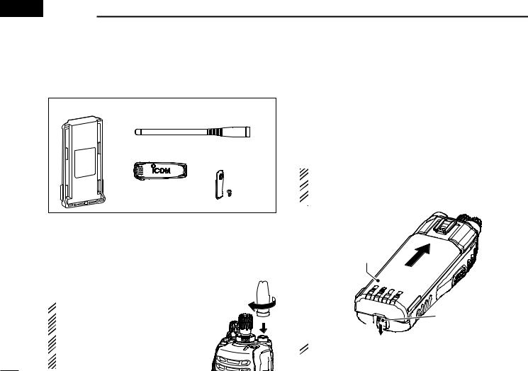
■■Supplied accessories
The following accessories are supplied.
Battery pack |
Flexible |
|
antenna |
Belt clip |
Connector cover |
|
(with screw) |
D Battery pack
To attach the battery pack:
Slide the battery pack on the back of the transceiver in the direction of the arrow (q), then lock it with the battery release button.
•Slide the battery pack until the battery release button makes a ‘click’ sound.
To release the battery pack:
Slide the battery release button in the direction of the arrow (w) as shown below. The battery pack is then released.
NEVER release or attach the battery pack when the trans-
 ceiver is wet or soiled. This may result water or dust get-
 ting into the transceiver/battery pack and may result in the
  transceiver being damaged.
■■Accessory attachments
D Flexible antenna
Connect the supplied flexible antenna to the antenna connector. 
 CAUTION:
 • NEVER carry the transceiver by
holding the antenna.
 • DO NOT connect the antenna other
than listed on p. 23.
 • Transmitting without an antenna may damage the transceiver.
Battery pack |
q |
|
Battery release |
w |
button |
|
 NOTE: Keep battery terminals clean. It’s a good idea to oc-
  casionally clean them.
1

D Belt clip
To attach the belt clip:
q Release the battery pack if it is attached.
w Slide the belt clip in the direction of the arrow until the belt clip is locked and makes a ‘click’ sound.
To detach the belt clip:
q Release the battery pack if it is attached.
w Pinch the clip (q), and slide the belt clip in the direction of the arrow (w).
w
q
ACCESSORIES 1
D Connector cover
Attach the connector cover when the optional equipment is not used.
To attach the connector cover:
q Insert the connector cover |
|
|
into the multi-connector. |
Multi- |
|
w Tighten the screw. |
||
CAUTION: |
connector |
|
w |
||
Attach the connector cover |
||
|
||
when the optional equipment |
|
|
is not used. Otherwise the |
q |
|
terminals of the multi-con- |
Connector |
|
nector may be shorted by |
||
metal object, etc., and this |
cover |
|
|
||
could damage the transceiver. |
|
|
To detach the connector cover: |
|
|
q Unscrew the screw using a |
|
|
phillips screwdriver. |
|
|
w Detach the connector cover |
|
|
for the optional equipment |
|
|
connector. |
q |
w
1
2
3
4
5
6
7
8
9
10
11
12
13
14
15
16
2

 2 PANEL DESCRIPTION
■■Front panel |
|
|
|
i |
q |
|
u |
|
|
w |
|
|
|
|
|
y |
e |
!5 |
t |
r |
|
||
!4 |
Speaker |
|
!3 |
Microphone |
|
Function display* |
1 |
|
|
|
|
|
(p. 5) |
|
 o*1
o*1
!2*1 
 !0*1
!0*1
2 |
*1 |
Simple/10-key types only |
!1* |
||
|
*2 |
10-key type only |
q ANTENNA CONNECTOR
Connects the supplied antenna. (p. 1)
w DEALER-PROGRAMMABLE KEY [EMR]
Desired function can be programmed by your dealer. (p. 6)
•[Emergency] is pre-programmed as default. (See the operating guide for details.)
e LED INDICATOR
Lights green while receiving a signal, or when the squelch is open.
Lights red while transmitting.
The LED indicator indicates some information. (Nondisplay type only) (p. 16)
r DEALER-PROGRAMMABLE ABC SWITCH
Desired function can be programmed to each position (A, B or C) independently by your dealer. (p. 11)
To activate the pre-programmed function, set the white line of the ABC switch to the position A, B or C.
White line
When the white line of the ABC switch is set to the position C, the pre-programmed function at position C will be activated.
3

t CHANNEL INDICATOR
Lights white according to the “Backlight” setting of the user set mode.
When you rotate [Rotary selector] to select the channel or zone, set the desired channel/zone number to this point.
y DEALER-PROGRAMMABLE TOGGLE SWITCH
Desired function can be programmed by your dealer. (p. 11)
When the toggle switch is set to the left side (‘ ’), the preprogrammed function will be activated.
u VOLUME CONTROL [VOL]
Rotate to turn the power ON/OFF and adjust the audio level.
i ROTARY SELECTOR
Rotate to select the pre-programmed memory channels or the operating zone. (Depending on the pre-setting)
•The channel/zone that is positioned to the channel indicator (t) is selected as the operating channel/zone.
•Depending on the pre-setting, selecting channel 1 using the rotary selector starts a scan. (Rotary Selector Home function)
o DEALER-PROGRAMMABLE KEYS [I]/[II]/[III]/[Ω]/[≈]/[∫]/[√] (Simple/10-key types only) Desired function can be programmed independently by your dealer. (p. 6)
!0APP KEY [APP] (Simple/10-key types only)
Desired function can be programmed by your dealer. (p. 6)
PANEL DESCRIPTION 2
!110-KEYPAD (10-key type only)
The keypad allows you to enter digits to:
•Select memory channels, tone channels and DTMF codes (while in the DTMF code channel selection mode.)
•Start up with the password
•Input the Individual ID code for digital operation. (Depending on the pre-setting)
!2HOME KEY [HOME] (Simple/10-key types only)
Desired function can be programmed by your dealer. (p. 6)
• [Home] is pre-programmed as default. (See p. 7 for details.)
!3PTT SWITCH [PTT]
Push and hold to transmit; release to receive.
•Depending on the pre-setting, when an external unit with its own PTT switch* is connected to the multi-connector, the transceiver’s [PTT] is disabled.
*Such as an optional speaker-microphone or headset.
!4DEALER-PROGRAMMABLE KEYS
[Side1]/[Side2]/[Side3]
Desired function can be programmed independently by your dealer. (p. 6)
!5MULTI-CONNECTOR
Connect optional equipment.
Connector cover
NOTE: Attach the connector cover when the optional equipment is not used.
See p. 2 for details.
1
2
3
4
5
6
7
8
9
10
11
12
13
14
15
16
4
2 PANEL DESCRIPTION
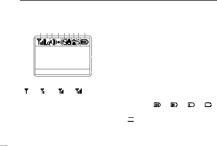
■■Function display (Simple/10-key types only)
q w e r tyui o
001 ch-01 |
|
|
! |
|
|||
IC-F9011 |
|
|
|
MON CLCK |
ZONE |
|
! |
|
q SIGNAL STRENGTH INDICATOR
Indicates relative signal strength level.
Weak
 Strong
w LOW POWER INDICATOR
Appears when low output power is selected.
• When high output power is selected, no indicator appears.
e AUDIBLE INDICATOR
Appears when the channel is in the ‘audible’ (unmute) condition.
r COMPANDER INDICATOR
Appears when the compander function* is activated.
* Analog mode operation only.
t SCRAMBLER INDICATOR
Appears when the voice scrambler or encryption function is activated.
y BELL INDICATOR
Appears/blinks when the matched signal is received, according to the pre-programming.
u TELEPHONE INDICATOR
Appears when a phone call* is received.
*P25 operation only.
iSHORT MESSAGE INDICATOR
Appears when an Status message or Short message is received.
o BATTERY INDICATOR
Appears or blinks when the battery power decreases to a specified level.
Indication |
|
|
|
|
|
|
|
|
|
|
|
Battery level |
Full |
Middle |
Charging |
No battery |
|
required |
|||||
|
|
|
|


 blinks when the battery is exhausted.
5
 Loading...