


 Loading...
HP ENVY 13
Maintenance and Service Guide
Document Part Number: 530626-001
September 2009
This guide is a troubleshooting reference used for maintaining and servicing the computer. It provides comprehensive information on identifying computer features, components, and spare parts; troubleshooting computer problems; and performing computer disassembly procedures.
© Copyright 2009 Hewlett-Packard Development Company, L.P.
ATI and ATI Mobility Radeon are trademarks of Advanced Micro Devices, Inc. Bluetooth is a trademark owned by its proprietor and used by Hewlett-Packard Company under license. Intel and Core are trademarks of Intel Corporation in the U.S. and other countries. Microsoft and Windows are U.S. registered trademarks of Microsoft Corporation. SD Logo is a trademark of its proprietor.
The information contained herein is subject to change without notice. The only warranties for HP products and services are set forth in the express warranty statements accompanying such products and services. Nothing herein should be construed as constituting an additional warranty. HP shall not be liable for technical or editorial errors or omissions contained herein.
First Edition: September 2009
Document Part Number: 530626-001

Safety warning notice
ÅWARNING: To reduce the possibility of heat-related injuries or of overheating the computer, do not place the computer directly on your lap or obstruct the computer air vents. Use the computer only on a hard, flat surface. Do not allow another hard surface, such as an adjoining optional printer, or a soft surface, such as pillows or rugs or clothing, to block airflow. Also, do not allow the AC adapter to contact the skin or a soft surface, such as pillows or rugs or clothing, during operation. The computer and the AC adapter comply with the user-accessible surface temperature limits defined by the International Standard for Safety of Information Technology Equipment (IEC 60950).

Contents
1Product description
2External component identification
Top components. . . . . . . . . . . . . . . . . . . . . . . . . . . . . . . . . . . . . . . . . . . . . . . . . . . . . . . . . . . . . . . . . . . . . . 2–1 Display components . . . . . . . . . . . . . . . . . . . . . . . . . . . . . . . . . . . . . . . . . . . . . . . . . . . . . . . . . . . . . . . 2–1 Button . . . . . . . . . . . . . . . . . . . . . . . . . . . . . . . . . . . . . . . . . . . . . . . . . . . . . . . . . . . . . . . . . . . . . . . . . . 2–2 Keys . . . . . . . . . . . . . . . . . . . . . . . . . . . . . . . . . . . . . . . . . . . . . . . . . . . . . . . . . . . . . . . . . . . . . . . . . . . 2–3 Lights . . . . . . . . . . . . . . . . . . . . . . . . . . . . . . . . . . . . . . . . . . . . . . . . . . . . . . . . . . . . . . . . . . . . . . . . . . 2–4 TouchPad and TouchPad buttons . . . . . . . . . . . . . . . . . . . . . . . . . . . . . . . . . . . . . . . . . . . . . . . . . . . . . 2–5
Front components. . . . . . . . . . . . . . . . . . . . . . . . . . . . . . . . . . . . . . . . . . . . . . . . . . . . . . . . . . . . . . . . . . . . . 2–6 Left-side components. . . . . . . . . . . . . . . . . . . . . . . . . . . . . . . . . . . . . . . . . . . . . . . . . . . . . . . . . . . . . . . . . . 2–6 Right-side components. . . . . . . . . . . . . . . . . . . . . . . . . . . . . . . . . . . . . . . . . . . . . . . . . . . . . . . . . . . . . . . . . 2–7 Bottom components . . . . . . . . . . . . . . . . . . . . . . . . . . . . . . . . . . . . . . . . . . . . . . . . . . . . . . . . . . . . . . . . . . . 2–8
3 Illustrated parts catalog
Service tag . . . . . . . . . . . . . . . . . . . . . . . . . . . . . . . . . . . . . . . . . . . . . . . . . . . . . . . . . . . . . . . . . . . . . . . . . . 3–1 Computer major components . . . . . . . . . . . . . . . . . . . . . . . . . . . . . . . . . . . . . . . . . . . . . . . . . . . . . . . . . . . . 3–3 Mass storage devices . . . . . . . . . . . . . . . . . . . . . . . . . . . . . . . . . . . . . . . . . . . . . . . . . . . . . . . . . . . . . . . . . . 3–6 Miscellaneous parts . . . . . . . . . . . . . . . . . . . . . . . . . . . . . . . . . . . . . . . . . . . . . . . . . . . . . . . . . . . . . . . . . . . 3–7 Sequential part number listing . . . . . . . . . . . . . . . . . . . . . . . . . . . . . . . . . . . . . . . . . . . . . . . . . . . . . . . . . . . 3–8
Maintenance and Service Guide |
iv |

Contents
4 Removal and replacement procedures
Preliminary replacement requirements . . . . . . . . . . . . . . . . . . . . . . . . . . . . . . . . . . . . . . . . . . . . . . . . . . . . 4–1 Tools required . . . . . . . . . . . . . . . . . . . . . . . . . . . . . . . . . . . . . . . . . . . . . . . . . . . . . . . . . . . . . . . . . . . . 4–1 Service considerations. . . . . . . . . . . . . . . . . . . . . . . . . . . . . . . . . . . . . . . . . . . . . . . . . . . . . . . . . . . . . . 4–1 Grounding guidelines . . . . . . . . . . . . . . . . . . . . . . . . . . . . . . . . . . . . . . . . . . . . . . . . . . . . . . . . . . . . . . 4–2 Service tag . . . . . . . . . . . . . . . . . . . . . . . . . . . . . . . . . . . . . . . . . . . . . . . . . . . . . . . . . . . . . . . . . . . . . . . . . . 4–5 Component replacement procedures . . . . . . . . . . . . . . . . . . . . . . . . . . . . . . . . . . . . . . . . . . . . . . . . . . . . . . 4–6 Computer feet . . . . . . . . . . . . . . . . . . . . . . . . . . . . . . . . . . . . . . . . . . . . . . . . . . . . . . . . . . . . . . . . . . . . 4–6 Battery. . . . . . . . . . . . . . . . . . . . . . . . . . . . . . . . . . . . . . . . . . . . . . . . . . . . . . . . . . . . . . . . . . . . . . . . . . 4–7 Top cover . . . . . . . . . . . . . . . . . . . . . . . . . . . . . . . . . . . . . . . . . . . . . . . . . . . . . . . . . . . . . . . . . . . . . . . 4–8 Keyboard. . . . . . . . . . . . . . . . . . . . . . . . . . . . . . . . . . . . . . . . . . . . . . . . . . . . . . . . . . . . . . . . . . . . . . . 4–10 Digital Media Slot board. . . . . . . . . . . . . . . . . . . . . . . . . . . . . . . . . . . . . . . . . . . . . . . . . . . . . . . . . . . 4–12 Speaker assembly . . . . . . . . . . . . . . . . . . . . . . . . . . . . . . . . . . . . . . . . . . . . . . . . . . . . . . . . . . . . . . . . 4–13 Mass storage device . . . . . . . . . . . . . . . . . . . . . . . . . . . . . . . . . . . . . . . . . . . . . . . . . . . . . . . . . . . . . . 4–15 WLAN module . . . . . . . . . . . . . . . . . . . . . . . . . . . . . . . . . . . . . . . . . . . . . . . . . . . . . . . . . . . . . . . . . . 4–16 Bluetooth module . . . . . . . . . . . . . . . . . . . . . . . . . . . . . . . . . . . . . . . . . . . . . . . . . . . . . . . . . . . . . . . . 4–18 Display assembly . . . . . . . . . . . . . . . . . . . . . . . . . . . . . . . . . . . . . . . . . . . . . . . . . . . . . . . . . . . . . . . . 4–19 System board. . . . . . . . . . . . . . . . . . . . . . . . . . . . . . . . . . . . . . . . . . . . . . . . . . . . . . . . . . . . . . . . . . . . 4–20 Power connector cable . . . . . . . . . . . . . . . . . . . . . . . . . . . . . . . . . . . . . . . . . . . . . . . . . . . . . . . . . . . . 4–23 SATA cable. . . . . . . . . . . . . . . . . . . . . . . . . . . . . . . . . . . . . . . . . . . . . . . . . . . . . . . . . . . . . . . . . . . . . 4–24 RTC battery. . . . . . . . . . . . . . . . . . . . . . . . . . . . . . . . . . . . . . . . . . . . . . . . . . . . . . . . . . . . . . . . . . . . . 4–25 Memory module . . . . . . . . . . . . . . . . . . . . . . . . . . . . . . . . . . . . . . . . . . . . . . . . . . . . . . . . . . . . . . . . . 4–26 Fan/heat sink assembly . . . . . . . . . . . . . . . . . . . . . . . . . . . . . . . . . . . . . . . . . . . . . . . . . . . . . . . . . . . . 4–27
5 Setup Utility (BIOS)
Starting Setup Utility . . . . . . . . . . . . . . . . . . . . . . . . . . . . . . . . . . . . . . . . . . . . . . . . . . . . . . . . . . . . . . . . . . 5–1 Using Setup Utility. . . . . . . . . . . . . . . . . . . . . . . . . . . . . . . . . . . . . . . . . . . . . . . . . . . . . . . . . . . . . . . . . . . . 5–1 Changing the language of Setup Utility . . . . . . . . . . . . . . . . . . . . . . . . . . . . . . . . . . . . . . . . . . . . . . . . 5–1 Navigating and selecting in Setup Utility . . . . . . . . . . . . . . . . . . . . . . . . . . . . . . . . . . . . . . . . . . . . . . . 5–2 Displaying system information . . . . . . . . . . . . . . . . . . . . . . . . . . . . . . . . . . . . . . . . . . . . . . . . . . . . . . . 5–2 Restoring default settings in Setup Utility . . . . . . . . . . . . . . . . . . . . . . . . . . . . . . . . . . . . . . . . . . . . . . 5–2 Exiting Setup Utility . . . . . . . . . . . . . . . . . . . . . . . . . . . . . . . . . . . . . . . . . . . . . . . . . . . . . . . . . . . . . . . 5–3 Setup Utility Menus . . . . . . . . . . . . . . . . . . . . . . . . . . . . . . . . . . . . . . . . . . . . . . . . . . . . . . . . . . . . . . . . . . . 5–3 Main menu . . . . . . . . . . . . . . . . . . . . . . . . . . . . . . . . . . . . . . . . . . . . . . . . . . . . . . . . . . . . . . . . . . . . . . 5–3 Security menu . . . . . . . . . . . . . . . . . . . . . . . . . . . . . . . . . . . . . . . . . . . . . . . . . . . . . . . . . . . . . . . . . . . . 5–3 System Configuration menu . . . . . . . . . . . . . . . . . . . . . . . . . . . . . . . . . . . . . . . . . . . . . . . . . . . . . . . . . 5–4 Diagnostics menu . . . . . . . . . . . . . . . . . . . . . . . . . . . . . . . . . . . . . . . . . . . . . . . . . . . . . . . . . . . . . . . . . 5–4 Updating the BIOS. . . . . . . . . . . . . . . . . . . . . . . . . . . . . . . . . . . . . . . . . . . . . . . . . . . . . . . . . . . . . . . . . . . . 5–5 Updating the BIOS . . . . . . . . . . . . . . . . . . . . . . . . . . . . . . . . . . . . . . . . . . . . . . . . . . . . . . . . . . . . . . . . 5–5
v |
Maintenance and Service Guide |

Contents
6 Specifications
Computer specifications. . . . . . . . . . . . . . . . . . . . . . . . . . . . . . . . . . . . . . . . . . . . . . . . . . . . . . . . . . . . . . . . 6–1 13.1-in HD+ display specifications . . . . . . . . . . . . . . . . . . . . . . . . . . . . . . . . . . . . . . . . . . . . . . . . . . . . . . . 6–2 13.1-in HD display specifications . . . . . . . . . . . . . . . . . . . . . . . . . . . . . . . . . . . . . . . . . . . . . . . . . . . . . . . . 6–3 Hard drive specifications . . . . . . . . . . . . . . . . . . . . . . . . . . . . . . . . . . . . . . . . . . . . . . . . . . . . . . . . . . . . . . . 6–4 Blu-ray ROM DVD±R/RW SuperMulti Double-Layer Drive specifications . . . . . . . . . . . . . . . . . . . . . . . 6–5 DVD±RW and CD-RW SuperMulti Double-Layer Combo Drive specifications. . . . . . . . . . . . . . . . . . . . 6–6 System DMA specifications. . . . . . . . . . . . . . . . . . . . . . . . . . . . . . . . . . . . . . . . . . . . . . . . . . . . . . . . . . . . . 6–7 System memory map specifications. . . . . . . . . . . . . . . . . . . . . . . . . . . . . . . . . . . . . . . . . . . . . . . . . . . . . . . 6–7 System interrupt specifications . . . . . . . . . . . . . . . . . . . . . . . . . . . . . . . . . . . . . . . . . . . . . . . . . . . . . . . . . . 6–8 System I/O address specifications . . . . . . . . . . . . . . . . . . . . . . . . . . . . . . . . . . . . . . . . . . . . . . . . . . . . . . . . 6–9
7 Screw listing
Phillips PM2.0×6.0 screw . . . . . . . . . . . . . . . . . . . . . . . . . . . . . . . . . . . . . . . . . . . . . . . . . . . . . . . . . . . . . . 7–1 Phillips PM2.0×6.0 screw . . . . . . . . . . . . . . . . . . . . . . . . . . . . . . . . . . . . . . . . . . . . . . . . . . . . . . . . . . . . . . 7–2 Phillips PM2.0×3.0 screw . . . . . . . . . . . . . . . . . . . . . . . . . . . . . . . . . . . . . . . . . . . . . . . . . . . . . . . . . . . . . . 7–3 Phillips PM1.5×1.5 screw . . . . . . . . . . . . . . . . . . . . . . . . . . . . . . . . . . . . . . . . . . . . . . . . . . . . . . . . . . . . . . 7–4 Phillips PM2.0×4.0 screw . . . . . . . . . . . . . . . . . . . . . . . . . . . . . . . . . . . . . . . . . . . . . . . . . . . . . . . . . . . . . . 7–5 Phillips PM1.5×3.0 screw . . . . . . . . . . . . . . . . . . . . . . . . . . . . . . . . . . . . . . . . . . . . . . . . . . . . . . . . . . . . . . 7–7 Phillips PM2.0×5.0 screw . . . . . . . . . . . . . . . . . . . . . . . . . . . . . . . . . . . . . . . . . . . . . . . . . . . . . . . . . . . . . . 7–9
8 Backup and recovery
Creating recovery discs . . . . . . . . . . . . . . . . . . . . . . . . . . . . . . . . . . . . . . . . . . . . . . . . . . . . . . . . . . . . . . . . 8–2 Backing up your information . . . . . . . . . . . . . . . . . . . . . . . . . . . . . . . . . . . . . . . . . . . . . . . . . . . . . . . . . . . . 8–3 Using Windows Backup and Restore . . . . . . . . . . . . . . . . . . . . . . . . . . . . . . . . . . . . . . . . . . . . . . . . . . 8–4 Using system restore points . . . . . . . . . . . . . . . . . . . . . . . . . . . . . . . . . . . . . . . . . . . . . . . . . . . . . . . . . 8–4 Performing a recovery . . . . . . . . . . . . . . . . . . . . . . . . . . . . . . . . . . . . . . . . . . . . . . . . . . . . . . . . . . . . . . . . . 8–5 Recovering from the recovery discs . . . . . . . . . . . . . . . . . . . . . . . . . . . . . . . . . . . . . . . . . . . . . . . . . . . 8–5
Maintenance and Service Guide |
vi |

Contents
9 Connector pin assignments
Audio-in (microphone). . . . . . . . . . . . . . . . . . . . . . . . . . . . . . . . . . . . . . . . . . . . . . . . . . . . . . . . . . . . . . . . . 9–1
Audio-out (headphone) . . . . . . . . . . . . . . . . . . . . . . . . . . . . . . . . . . . . . . . . . . . . . . . . . . . . . . . . . . . . . . . . 9–2
HDMI . . . . . . . . . . . . . . . . . . . . . . . . . . . . . . . . . . . . . . . . . . . . . . . . . . . . . . . . . . . . . . . . . . . . . . . . . . . . . . 9–3
Universal Serial Bus. . . . . . . . . . . . . . . . . . . . . . . . . . . . . . . . . . . . . . . . . . . . . . . . . . . . . . . . . . . . . . . . . . . 9–4
10Power cord set requirements
Requirements for all countries and regions . . . . . . . . . . . . . . . . . . . . . . . . . . . . . . . . . . . . . . . . . . . . . . . . 10–1 Requirements for specific countries and regions . . . . . . . . . . . . . . . . . . . . . . . . . . . . . . . . . . . . . . . . . . . . 10–2
11Recycling
Battery . . . . . . . . . . . . . . . . . . . . . . . . . . . . . . . . . . . . . . . . . . . . . . . . . . . . . . . . . . . . . . . . . . . . . . . . . . . . 11–1
Display . . . . . . . . . . . . . . . . . . . . . . . . . . . . . . . . . . . . . . . . . . . . . . . . . . . . . . . . . . . . . . . . . . . . . . . . . . . . 11–1
Index
vii |
Maintenance and Service Guide |

1
Product description
Category |
Description |
|
|
Product name |
HP ENVY 13 Notebook PC |
|
|
Processors |
Intel® Core™2 Duo SL9600 2.13-GHz processor, 6-MB L2 cache, |
|
1066-MHz front side bus (FSB) |
|
Intel Core2 Duo SL9400 1.86-GHz processor, 6-MB L2 cache, |
|
1066-MHz FSB |
|
Intel Core2 Duo SU9600 1.60-GHz processor, 3-MB L2 cache, |
|
800-MHz FSB |
|
|
Chipset |
Northbridge: Intel GS45 800-MHz FSB |
|
Southbridge: Intel ICH-9M small form factor (SFF) |
|
|
Graphics |
ATI™ Mobility Radeon HD 4330 (M92 LP-S2) Discrete PCI Express |
|
Graphics with 512 MB of dedicated video memory (64M×16, 1.5V, |
|
667 MHz, DDR3 @1333 MHz) |
|
Supports ATI PowerXpress and switchable graphics solution |
|
Mobile Intel GMA 4500 MHD Universal Memory Architecture (UMA) |
|
integrated with shared video memory (dynamically allocated) with the |
|
following graphics memory allocations: |
|
■ Up to 1631 MB when total system memory is 4096 MB (on computer |
|
models equipped with a 64-bit operating system) |
|
■ Up to 1181 MB when total system memory is 4096 MB (on computer |
|
models equipped with a 32-bit operating system) |
|
■ Up to 669 MB when total system memory is 2048 MB (on all |
|
computer models) |
|
|
|
(Continued) |
Maintenance and Service Guide |
1–1 |

Product description
Category |
Description |
|
|
Panel |
13.1-in AntiGlare, high-definition (HD)+, light-emitting diode (LED) |
|
display assembly |
|
13.1-in AntiGlare, HD, LED display assembly |
|
16 × 9 wide aspect ratio |
|
Supports privacy filter |
|
Includes 2 wireless local-area network (WLAN) antennas |
|
|
Memory |
1-GB main system memory included on system board |
|
One memory module slot (not customer accessible/upgradeable), |
|
supports up to 4-GB memory (5-GB total system memory) |
|
Supports DDR3, 1066-MHz memory |
|
|
Mass storage devices |
Supports either 8-mm SATA 1.8-in hard drives or solid-state drives |
|
Supports HP ProtectSmart Hard Drive Protection |
|
Supports 160-GB solid-state drive |
|
Supports the following hard drive configurations: |
|
■ 250-GB, 5400-rpm |
|
■ 160-GB, 5400-rpm |
|
■ 120-GB, 5400-rpm |
|
|
Optical drive |
External USB support for the following: |
|
■ Blu-ray ROM DVD±R/RW SuperMulti Double-Layer Drive |
|
with LightScribe |
|
■ DVD±RW and CD-RW SuperMulti Double-Layer Combo Drive |
|
with LightScribe |
|
|
Microphone |
2 integrated omnidirectional digital microphones |
|
Microphone jack |
|
|
Webcam |
Low-light VGA camera |
|
Fixed (no tilt) |
|
Activity light |
|
640 × 480 by 24 frames per second |
|
|
|
(Continued) |
1–2 |
Maintenance and Service Guide |

Product description
Category |
Description |
|
|
Audio |
HD audio |
|
SRS logo requirement |
|
Dolby Home Theater technology |
|
Supports Microsoft Premium requirements |
|
HDX-branded stereo speakers |
|
Headphone jack |
|
|
Modem |
High-speed 56K data/fax modem |
|
Modem cable not included |
|
Supports no-modem option |
|
|
Ethernet |
Marvell 88E8072-B1 10/100/1000 Ethernet |
|
S3/S5 wake on LAN (AC mode only) |
|
Ethernet cable not included |
|
|
Power requirements |
65-W PAW AC adapter with localized cable plug support |
|
Battery options: |
|
■ 6-cell, 2.80-Ah (62-Wh) Li-ion battery |
|
■ 4-cell, 2.80-Ah (41-Wh) Li-ion battery |
|
|
Wireless |
Integrated WLAN options by way of wireless module |
|
2 wireless antennas built into display assembly |
|
Supports no-WLAN option |
|
Support for the following WLAN formats: |
|
■ Intel WiFi Link 5100 802.11 a/b/g/n |
|
■ Intel WiFi Link 5100 802.11 a/b/g/n with Bluetooth® |
|
■ Intel WiFi Link 5100 802.11 a/b/g |
|
■ Intel WiFi Link 5100 802.11 a/b/g with Bluetooth |
|
|
External media cards |
Digital Media Slot |
|
Supports the following digital card formats: |
|
■ MultiMediaCard |
|
■ MultiMediaCard Plus |
|
■ Secure Digital (SD) Memory Card |
|
■ SD High Capacity Memory Card |
|
|
|
(Continued) |
Maintenance and Service Guide |
1–3 |
Product description
Category |
Description |
|
|
Ports |
High-definition multimedia interface (HDMI) v1.3b supporting 1080p |
|
with HDCP key (HDMI-to-VGA adapter included) |
|
Headphone/microphone combo jack (stereo, supports jack detection |
|
per Microsoft Premium requirements) |
|
USB 2.0 ports (2, each capable of driving an external optical drive) |
|
AC adapter plug |
|
|
Keyboard/ |
Full-size 13.0-in painted keyboard |
pointing devices |
TouchPad with gesture support (media “M,” scroll, pinch, zoom) |
|
Taps enabled by default |
|
|
Serviceability |
AC adapter |
|
Battery (system) |
|
External optical drive |
|
|
Security |
Security cable slot with adapter |
Operating system |
Preinstalled: |
|
■ Microsoft® Windows® 7 Home Premium 64 |
|
■ Microsoft Windows 7 Home Professional 64 |
|
■ Configurable Linux embedded |
|
|
1–4 |
Maintenance and Service Guide |
2
External component identification
Components included with the computer may vary by region and model. The illustrations in this chapter identify the standard features on most computer models.
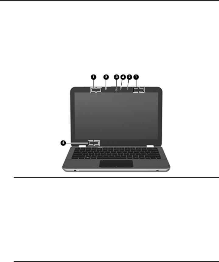
Top components
Display components
Item |
Component |
Description |
|
|
|
(1) |
Wireless antennas (2) |
Send and receive signals from one or more wireless devices. These antennas |
|
|
are not visible from the outside of the computer. |
|
|
To see wireless regulatory notices, refer to the section of the Regulatory, |
|
|
Safety and Environmental Notices that applies to your country or region. |
|
|
These notices are located in Help and Support. |
|
|
For optimal transmission, keep the areas immediately around the |
|
|
antennas free from obstructions. |
|
|
|
(2) |
Internal microphones (2) |
Record sound. |
|
|
|
(3) |
Webcam |
Records video and captures still photographs. |
|
|
|
(4) |
Webcam light |
On: The webcam is in use. |
|
|
|
(5) |
Internal display switch |
Turns off the display and initiates Sleep if the display is closed while the power |
|
|
is on. |
Thecomputer.internal display switch is not visible from the outside of the
Maintenance and Service Guide |
2–1 |
External component identification
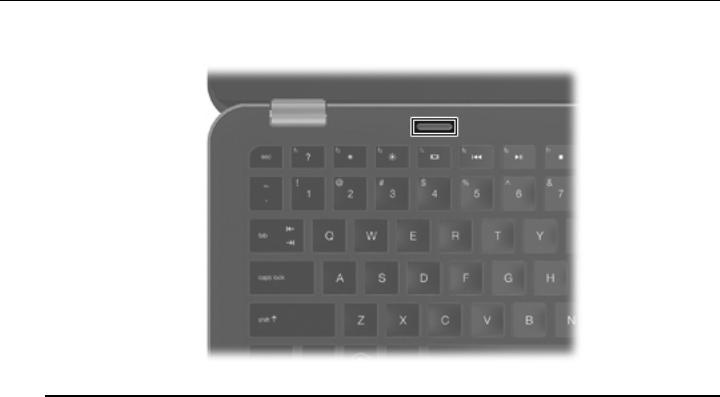
Button
Component |
Description |
|
|
Power button |
■ When the computer is off, press the button to turn on the computer. |
|
■ When the computer is on, press the button briefly to initiate Sleep. |
|
■ When the computer is in the Sleep state, press the button briefly to |
|
exit Sleep. |
|
■ When the computer is in Hibernation, press the button briefly to |
|
exit Hibernation. |
|
If the computer has stopped responding and Windows shutdown procedures |
|
are ineffective, press and hold the power button for at least 5 seconds to turn |
|
off the computer. |
|
To learn more about your power settings, select Start > Control Panel > |
|
System and Security > Power Options. |
|
|
2–2 |
Maintenance and Service Guide |
External component identification
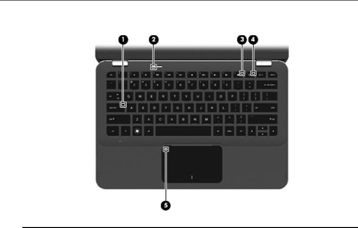
Keys
Item |
Component |
Description |
|
|
|
(1) |
esc key |
Displays system information when pressed in combination with the fn key. |
|
|
|
(2) |
fn key |
Executes frequently used system functions when pressed in combination with |
|
|
an arrow key or the esc key. |
|
|
|
(3) |
Windows logo key |
Displays the Windows Start menu. |
|
|
|
(4) |
Windows applications key |
Displays a shortcut menu for items beneath the cursor. |
|
|
|
(5) |
Action keys |
Execute frequently used system functions. |
|
|
|
Maintenance and Service Guide |
2–3 |
External component identification
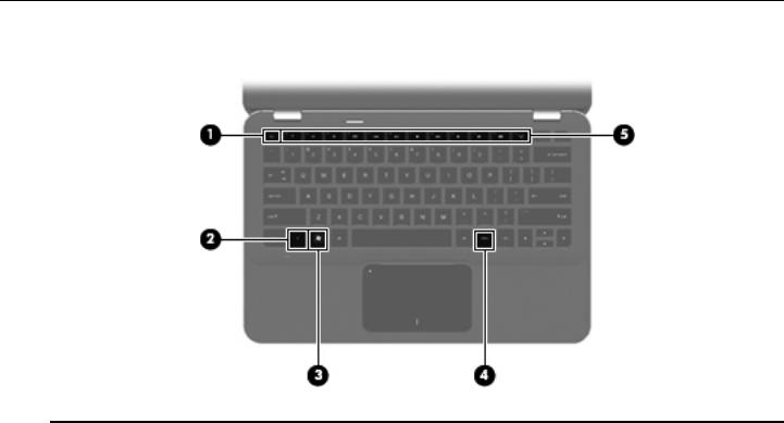
Lights
Item |
Component |
Description |
|
|
|
(1) |
Caps lock light |
White: Caps lock is on. |
|
|
|
(2) |
Power light |
■ White: The computer is on. |
|
|
■ Blinking white: The computer is in the Sleep state. |
|
|
■ Off: The computer is off or in Hibernation. |
|
|
|
(3) |
Wireless light |
■ Off: An integrated wireless device, such as a WLAN device and/or a |
|
|
Bluetooth device, is on. |
|
|
Wireless devices are enabled at the factory. |
|
|
■ Amber: All wireless devices are off. |
|
|
|
(4) |
Mute light |
Amber: Computer sound is off. |
|
|
|
(5) |
TouchPad light |
■ Amber: The TouchPad is off. |
|
|
■ Off: The TouchPad is on. |
|
|
|
2–4 |
Maintenance and Service Guide |
External component identification
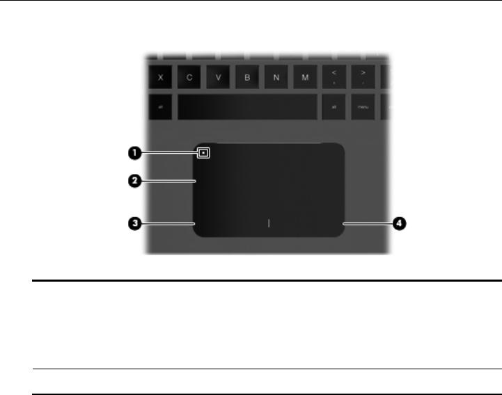
TouchPad and TouchPad buttons
Item |
Component |
Description |
|
|
|
(1) |
TouchPad on/off button |
Turns the TouchPad on and off. Lightly press the button and hold for |
|
|
2 seconds to turn the TouchPad on and off. |
|
|
|
(2) |
TouchPad* |
Moves the pointer and selects or activates items on the screen. |
|
|
|
(3) |
Left TouchPad button* |
Functions like the left button on an external mouse. |
|
|
|
(4) |
Right TouchPad button* |
Functions like the right button on an external mouse. |
*This table describes factory settings. To view and change pointing device preferences, select Start > Devices and Printers. Then, right-click the device representing your computer, and select Mouse settings.
Maintenance and Service Guide |
2–5 |

External component identification
Front components
Component |
Description |
|
|
Speakers (2) |
Produce sound. |
|
|
Left-side components
Item |
Component |
Description |
|
|
|
(1) |
Vent |
Enables airflow to cool internal components. |
|
|
The computer fan starts up automatically to cool internal components |
|
|
and prevent overheating. It is normal for the internal fan to cycle on and |
|
|
off during routine operation. |
|
|
|
(2) |
Power connector |
Connects an AC adapter. |
|
|
|
(3) |
Battery light |
■ Off: The computer is running on battery power. |
|
|
■ Blinking amber: The battery has reached a low battery level, a critical |
|
|
battery level, or there is a battery error. |
|
|
■ Amber: A battery is charging. |
|
|
■ White: The computer is connected to external power and the battery is |
|
|
fully charged. |
|
|
|
(4) |
Digital Media Slot |
Supports the following digital card formats: |
|
|
■ MultiMediaCard |
|
|
■ MultiMediaCard Plus |
|
|
■ Secure Digital Memory Card |
|
|
■ Secure Digital High Capacity Memory Card |
|
|
|
2–6 |
Maintenance and Service Guide |
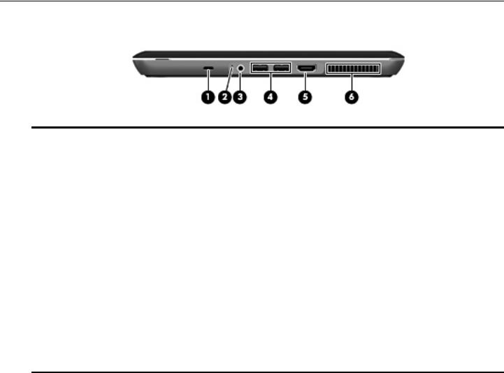
External component identification
Right-side components
Item |
Component |
Description |
|
|
|
(1) |
Security cable slot |
Attaches an optional security cable to the computer. |
|
|
The security cable is designed to act as a deterrent, but it may not |
|
|
prevent the computer from being mishandled or stolen. |
|
|
|
(2) |
Drive light |
■ Blinking white: The hard drive is being accessed. |
|
|
■ Amber: HP ProtectSmart Hard Drive Protection has temporarily parked the |
|
|
hard drive. |
|
|
|
(3) |
Audio-out (headphone) jack/Audio-in |
Produces sound when connected to optional powered stereo speakers, |
|
(microphone) jack |
headphones, earbuds, a headset, or television audio. Also connects an |
|
|
optional headset microphone. |
|
|
When a device is connected to the jack, the device speakers |
|
|
are disabled. |
|
|
|
(4) |
USB ports (2) |
Connect optional USB devices. |
|
|
|
(5) |
HDMI port |
Connects an optional video or audio device, such as a high-definition |
|
|
television, or any compatible digital or audio component. |
|
|
|
(6) |
Vent |
Enables airflow to cool internal components. |
|
|
The computer fan starts up automatically to cool internal components |
|
|
and prevent overheating. It is normal for the internal fan to cycle on and |
off during routine operation.
Maintenance and Service Guide |
2–7 |
External component identification
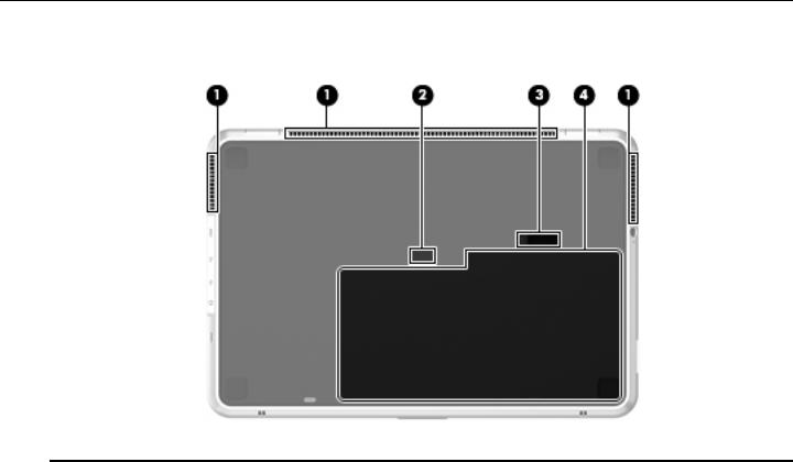
Bottom components
Item |
Component |
Description |
|
|
|
(1) |
Vents (3) |
Enable airflow to cool internal components. |
|
|
The computer fan starts up automatically to cool internal components |
|
|
and prevent overheating. It is normal for the internal fan to cycle on and |
|
|
off during routine operation. |
|
|
|
(2) |
Accessory battery connector |
Connects an optional accessory battery. |
|
|
|
(3) |
Battery release latch |
Releases the battery from the battery bay. |
|
|
|
(4) |
Battery bay |
Holds the battery. |
|
|
The battery is preinstalled in the battery bay at the factory. |
2–8 |
Maintenance and Service Guide |
3
Illustrated parts catalog
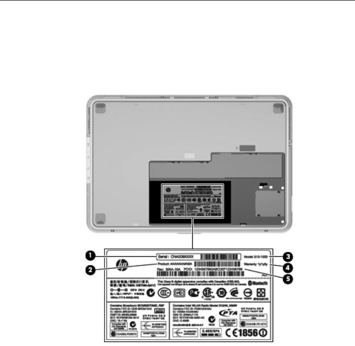
Service tag
When ordering parts or requesting information, provide the computer serial number and model number provided on the service tag.
Maintenance and Service Guide |
3–1 |
Illustrated parts catalog
Item |
Component |
Description |
|
|
|
(1) |
Serial number (s/n) |
This is an alphanumeric identifier that is unique to each product. |
|
|
|
(2) |
Product name |
This is the product name affixed to the front of the computer. |
|
|
|
(3) |
Model description |
This is the alphanumeric identifier used to locate documents, |
|
|
drivers, and support for the computer. |
|
|
|
(4) |
Warranty period |
This number describes the duration (in years) of the warranty |
|
|
period for the computer. |
|
|
|
(5) |
Part number/Product number (p/n) |
This number provides specific information about the product’s |
|
|
hardware components. The part number helps a service |
|
|
technician determine what components and parts are needed. |
|
|
|
3–2 |
Maintenance and Service Guide |

Illustrated parts catalog
Computer major components
Maintenance and Service Guide |
3–3 |

Illustrated parts catalog
Item Description |
Spare part number |
(1)13.1-in, AntiGlare, LED display assembly (includes webcam module and cable, microphone and cable, 2 WLAN antenna transceivers and cables, nameplate, and logo):
|
High-definition+ (1600 × 900) display assembly |
538320-001 |
|
High-definition (1366 × 768) display assembly |
538319-001 |
|
|
|
(2) |
Top cover (includes TouchPad board, TouchPad bracket, and TouchPad cable) |
538343-001 |
(3)Keyboard (includes keyboard cable):
|
For use in Brazil |
538308-201 |
|
For use in Denmark, Finland, and Norway |
538308-DH1 |
|
For use in France |
538308-051 |
|
For use in French Canada |
538308-121 |
|
For use in Germany |
538308-041 |
|
For use in Italy |
538308-061 |
|
For use in Latin America |
538308-161 |
|
For use in the Netherlands |
538308-B31 |
|
For use in Russia |
538308-251 |
|
For use in Saudi Arabia |
538308-171 |
|
For use in South Korea |
538308-AD1 |
|
For use in Spain |
538308-071 |
|
For use in the United Kingdom and Singapore |
538308-031 |
|
For use in the United States |
538308-001 |
|
|
|
(4) |
Power connector cable |
538338-001 |
|
|
|
(5) |
System board (includes replacement thermal material): |
|
|
SL9600 system board equipped with an Intel Core2 Duo 2.13-GHz processor |
538317-001 |
|
(1066-MHz FSB and 6-MB L2 cache) |
|
|
SL9400 system board equipped with an Intel Core2 Duo 1.86-GHz processor |
538316-001 |
|
(1066-MHz FSB and 6-MB L2 cache) |
|
|
SU9600 system board equipped with an Intel Core2 Duo 1.60-GHz processor |
577100-001 |
|
(800-MHz FSB and 3-MB L2 cache) |
|
(6)WLAN module:
Intel WiFi Link 5100 802.11a/b/g/n WLAN module for use in Andorra, Antigua and Barbuda, 506678-001 Argentina, Aruba, Australia, Austria, Azerbaijan, Bahamas, Bahrain, Barbados, Belgium,
Bermuda, Bolivia, Bosnia, Brazil, Brunei, Bulgaria, Canada, the Cayman Islands, Chile, Colombia, Costa Rica, Croatia, Cyprus, the Czech Republic, Denmark,
the Dominican Republic, Ecuador, Egypt, El Salvador, Estonia, Finland, France,
French Guiana, Georgia, Germany, Ghana, Greece, Guadeloupe, Guam, Guatemala, Haiti, Herzegovina, Honduras, Hong Kong, Hungary, Iceland, India, Indonesia, Ireland, Israel, Italy, the Ivory Coast, Jamaica, Japan, Jordan, Kenya, Kuwait, Kyrgyzstan, Latvia, Lebanon, Liechtenstein, Lithuania, Luxembourg, Malawi, Malaysia, Malta, Martinique, Mauritius, Mexico, Monaco, Montenegro, Morocco, the Nether Antilles, the Netherlands, New Zealand, Nicaragua, Nigeria, Norway, Oman, Panama, Paraguay, the People’s Republic China, Peru, the Philippines, Poland, Portugal, Puerto Rico, Qatar, Romania, San Marino, Saudi Arabia, Senegal, Serbia, Singapore, Slovakia, Slovenia, South Africa, South Korea, Spain, Sweden, Switzerland, Taiwan, Tanzania, Thailand, Trinidad and Tobago, Turkey,
the United Arab Emirates, the United Kingdom, Uruguay, the U.S. Virgin Islands, the United States, Venezuela, and Vietnam
(Continued)
3–4 |
Maintenance and Service Guide |

Illustrated parts catalog
Item Description |
Spare part number |
(6)WLAN module (continued):
|
Intel WiFi Link 5100 802.11a/b/g WLAN module for use in Andorra, Antigua and Barbuda, |
506680-001 |
|
Argentina, Aruba, Australia, Austria, Azerbaijan, Bahamas, Bahrain, Barbados, Belgium, |
|
|
Bermuda, Bolivia, Bosnia, Brazil, Brunei, Bulgaria, Canada, the Cayman Islands, Chile, |
|
|
Colombia, Costa Rica, Croatia, Cyprus, the Czech Republic, Denmark, |
|
|
the Dominican Republic, Ecuador, Egypt, El Salvador, Estonia, Finland, France, |
|
|
French Guiana, Georgia, Germany, Ghana, Greece, Guadeloupe, Guam, Guatemala, Haiti, |
|
|
Herzegovina, Honduras, Hong Kong, Hungary, Iceland, India, Indonesia, Ireland, Israel, |
|
|
Italy, the Ivory Coast, Jamaica, Japan, Jordan, Kenya, Kuwait, Kyrgyzstan, Latvia, Lebanon, |
|
|
Liechtenstein, Lithuania, Luxembourg, Malawi, Malaysia, Malta, Martinique, Mauritius, |
|
|
Mexico, Monaco, Montenegro, Morocco, the Nether Antilles, the Netherlands, New Zealand, |
|
|
Nicaragua, Nigeria, Norway, Oman, Panama, Paraguay, the People’s Republic China, Peru, |
|
|
the Philippines, Poland, Portugal, Puerto Rico, Qatar, Romania, San Marino, Saudi Arabia, |
|
|
Senegal, Serbia, Singapore, Slovakia, Slovenia, South Africa, South Korea, Spain, Sweden, |
|
|
Switzerland, Taiwan, Tanzania, Thailand, Trinidad and Tobago, Turkey, |
|
|
the United Arab Emirates, the United Kingdom, Uruguay, the U.S. Virgin Islands, |
|
|
the United States, Venezuela, and Vietnam |
|
|
|
|
(7) |
Mass storage device: |
|
|
Hard drive (includes rubber isolator): |
|
|
■ 250-GB, 5400-rpm |
538327-001 |
|
■ 160-GB, 5400-rpm |
538326-001 |
|
■ 120-GB, 5400-rpm |
538325-001 |
|
|
|
|
160-GB solid-state drive (includes rubber isolator) |
538329-001 |
|
|
|
|
Hard Drive Mounting Kit, includes: |
538330-001 |
(8a) |
Mass storage device bracket |
|
(8b) |
Mass storage device rubber isolator |
|
|
|
|
|
Solid-state Drive Mounting Kit (not illustrated, includes mass storage device bracket and |
538331-001 |
|
mass storage device rubber isolator) |
|
|
|
|
(9) |
SATA cable |
538347-001 |
|
|
|
(10) |
Digital Media Slot board (includes cable) |
538337-001 |
|
|
|
(11) |
Fan/heat sink assembly (includes replacement thermal material) |
538340-001 |
|
|
|
(12) |
Bluetooth module |
537921-001 |
|
|
|
(13) |
Bluetooth module cable |
538339-001 |
|
|
|
(14) |
Speaker assembly |
538342-001 |
|
|
|
(15) |
RTC battery (includes double-sided tape) |
538345-001 |
(16)Memory module (1066-MHz, DDR3):
|
4096-MB |
538323-001 |
|
2048-MB |
538322-001 |
|
1024-MB |
538321-001 |
|
|
|
(17) |
Base enclosure (includes 3 rubber feet) |
538336-001 |
|
Rubber Feet Kit (not illustrated, includes 4 rubber feet) |
538346-001 |
|
|
|
(18) |
Battery (includes one rubber foot): |
|
|
6-cell, 2.80-Ah (62-Wh) Li-ion battery |
538335-001 |
|
4-cell, 2.80-Ah (41-Wh) Li-ion battery |
538334-001 |
|
|
|
Maintenance and Service Guide |
3–5 |
Illustrated parts catalog
Mass storage devices
Item Description |
Spare part number |
(1)Hard drive (includes rubber isolator):
|
250-GB, 5400-rpm hard drive |
538327-001 |
|
160-GB, 5400-rpm hard drive |
538326-001 |
|
120-GB, 5400-rpm hard drive |
538325-001 |
|
|
|
|
Hard Drive Mounting Kit (not illustrated, includes mass storage device bracket and |
538330-001 |
|
mass storage device rubber isolator) |
|
|
|
|
(2) |
160-GB solid-state drive (includes rubber isolator) |
538329-001 |
|
|
|
|
Solid-state Drive Mounting Kit (not illustrated, includes mass storage device |
538331-001 |
|
bracket and mass storage device rubber isolator) |
|
|
|
|
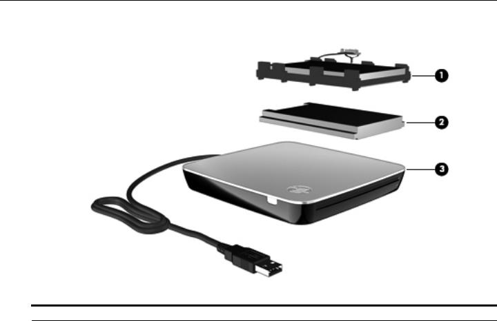
(3) |
External optical drive: |
|
|
Blu-ray ROM DVD±R/RW SuperMulti Double-Layer Drive with LightScribe |
538333-001 |
|
DVD±RW and CD-RW SuperMulti Double-Layer Combo Drive with LightScribe |
538332-001 |
|
|
|
3–6 |
Maintenance and Service Guide |

|
|
Illustrated parts catalog |
|
|
|
Miscellaneous parts |
|
|
|
|
|
|
Description |
Spare part number |
|
|
|
|
AC adapter: |
|
|
65-W PFC HP Smart Adapter |
530608-001 |
|
65-W HDX HP Smart Adapter |
576129-001 |
|
|
|
|
HDMI-to-VGA adapter |
530607-001 |
|
|
|
|
Power cord: |
|
|
For use in Argentina |
490371-D01 |
|
For use in Australia |
490371-011 |
|
For use in Brazil |
490371-201 |
|
For use in Europe, the Middle East, and Africa |
490371-021 |
|
For use in India |
490371-D61 |
|
For use in Italy |
490371-061 |
|
For use in the People’s Republic of China |
490371-AA1 |
|
For use in South Africa |
490371-AR1 |
|
For use in South Korea |
490371-AD1 |
|
For use in Switzerland |
490371-111 |
|
For use in Taiwan |
490371-AB1 |
|
For use in the United Kingdom and Singapore |
490371-031 |
|
For use in North America |
490371-001 |
|
|
|
|
RJ45-to-USB adapter |
539614-001 |
|
|
|
|
Screw Kit: |
538341-001 |
|
Phillips PM2.0×6.0 screw |
|
Phillips PM2.0×5.0 screw
Phillips PM2.0×4.0 screw
Phillips PM2.0×3.0 screw
Phillips PM2.0×2.0 broadhead screw
Phillips PM1.5×3.0 screw
Phillips PM1.5×1.5 screw
Maintenance and Service Guide |
3–7 |

Illustrated parts catalog
Sequential part number listing
Spare part number |
Description |
|
|
490371-001 |
Power cord for use in North America |
|
|
490371-011 |
Power cord for use in Australia |
|
|
490371-021 |
Power cord for use in Europe, the Middle East, and Africa |
|
|
490371-031 |
Power cord for use in the United Kingdom and Singapore |
|
|
490371-061 |
Power cord for use in Italy |
|
|
490371-111 |
Power cord for use in Switzerland |
|
|
490371-201 |
Power cord for use in Brazil |
|
|
490371-AA1 |
Power cord for use in the People’s Republic of China |
|
|
490371-AB1 |
Power cord for use in Taiwan |
|
|
490371-AD1 |
Power cord for use in South Korea |
|
|
490371-AR1 |
Power cord for use in South Africa |
|
|
490371-D01 |
Power cord for use in Argentina |
|
|
490371-D61 |
Power cord for use in India |
|
|
506678-001 |
Intel WiFi Link 5100 802.11a/b/g/n WLAN module for use in Andorra, Antigua and Barbuda, |
|
Argentina, Aruba, Australia, Austria, Azerbaijan, Bahamas, Bahrain, Barbados, Belgium, Bermuda, |
|
Bolivia, Bosnia, Brazil, Brunei, Bulgaria, Canada, the Cayman Islands, Chile, Colombia, Costa Rica, |
|
Croatia, Cyprus, the Czech Republic, Denmark, the Dominican Republic, Ecuador, Egypt, |
|
El Salvador, Estonia, Finland, France, French Guiana, Georgia, Germany, Ghana, Greece, |
|
Guadeloupe, Guam, Guatemala, Haiti, Herzegovina, Honduras, Hong Kong, Hungary, Iceland, India, |
|
Indonesia, Ireland, Israel, Italy, the Ivory Coast, Jamaica, Japan, Jordan, Kenya, Kuwait, Kyrgyzstan, |
|
Latvia, Lebanon, Liechtenstein, Lithuania, Luxembourg, Malawi, Malaysia, Malta, Martinique, |
|
Mauritius, Mexico, Monaco, Montenegro, Morocco, the Nether Antilles, the Netherlands, |
|
New Zealand, Nicaragua, Nigeria, Norway, Oman, Panama, Paraguay, the People’s Republic China, |
|
Peru, the Philippines, Poland, Portugal, Puerto Rico, Qatar, Romania, San Marino, Saudi Arabia, |
|
Senegal, Serbia, Singapore, Slovakia, Slovenia, South Africa, South Korea, Spain, Sweden, |
|
Switzerland, Taiwan, Tanzania, Thailand, Trinidad and Tobago, Turkey, the United Arab Emirates, |
|
the United Kingdom, Uruguay, the U.S. Virgin Islands, the United States, Venezuela, and Vietnam |
|
|
506680-001 |
Intel WiFi Link 5100 802.11a/b/g WLAN module for use in Andorra, Antigua and Barbuda, Argentina, |
|
Aruba, Australia, Austria, Azerbaijan, Bahamas, Bahrain, Barbados, Belgium, Bermuda, Bolivia, |
|
Bosnia, Brazil, Brunei, Bulgaria, Canada, the Cayman Islands, Chile, Colombia, Costa Rica, Croatia, |
|
Cyprus, the Czech Republic, Denmark, the Dominican Republic, Ecuador, Egypt, El Salvador, |
|
Estonia, Finland, France, French Guiana, Georgia, Germany, Ghana, Greece, Guadeloupe, Guam, |
|
Guatemala, Haiti, Herzegovina, Honduras, Hong Kong, Hungary, Iceland, India, Indonesia, Ireland, |
|
Israel, Italy, the Ivory Coast, Jamaica, Japan, Jordan, Kenya, Kuwait, Kyrgyzstan, Latvia, Lebanon, |
|
Liechtenstein, Lithuania, Luxembourg, Malawi, Malaysia, Malta, Martinique, Mauritius, Mexico, |
|
Monaco, Montenegro, Morocco, the Nether Antilles, the Netherlands, New Zealand, Nicaragua, |
|
Nigeria, Norway, Oman, Panama, Paraguay, the People’s Republic China, Peru, the Philippines, |
|
Poland, Portugal, Puerto Rico, Qatar, Romania, San Marino, Saudi Arabia, Senegal, Serbia, |
|
Singapore, Slovakia, Slovenia, South Africa, South Korea, Spain, Sweden, Switzerland, Taiwan, |
|
Tanzania, Thailand, Trinidad and Tobago, Turkey, the United Arab Emirates, the United Kingdom, |
|
Uruguay, the U.S. Virgin Islands, the United States, Venezuela, and Vietnam |
(Continued)
3–8 |
Maintenance and Service Guide |

Illustrated parts catalog
Spare part number |
Description |
|
|
530607-001 |
HDMI-to-VGA adapter |
|
|
530608-001 |
65-W PFC HP Smart Adapter |
|
|
537921-001 |
Bluetooth module |
|
The Bluetooth module spare part kit does not include a Bluetooth module cable. The Bluetooth |
|
module cable is available using spare part number 538339-001. |
|
|
538308-001 |
Keyboard for use in the United States (includes keyboard cable) |
|
|
538308-031 |
Keyboard for use in the United Kingdom and Singapore (includes keyboard cable) |
|
|
538308-041 |
Keyboard for use in Germany (includes keyboard cable) |
|
|
538308-051 |
Keyboard for use in France (includes keyboard cable) |
|
|
538308-061 |
Keyboard for use in Italy (includes keyboard cable) |
|
|
538308-071 |
Keyboard for use in Spain (includes keyboard cable) |
|
|
538308-121 |
Keyboard for use in French Canada (includes keyboard cable) |
|
|
538308-161 |
Keyboard for use in Latin America (includes keyboard cable) |
|
|
538308-171 |
Keyboard for use in Saudi Arabia (includes keyboard cable) |
|
|
538308-201 |
Keyboard for use in Brazil (includes keyboard cable) |
|
|
538308-251 |
Keyboard for use in Russia (includes keyboard cable) |
|
|
538308-AD1 |
Keyboard for use in South Korea (includes keyboard cable) |
|
|
538308-B31 |
Keyboard for use in the Netherlands (includes keyboard cable) |
|
|
538308-DH1 |
Keyboard for use in Denmark, Finland, and Norway (includes keyboard cable) |
|
|
538316-001 |
SL9400 system board equipped with an Intel Core2 Duo 1.86-GHz processor (1066-MHz FSB and |
|
6-MB L2 cache, includes replacement thermal material) |
|
|
538317-001 |
SL9600 system board equipped with an Intel Core2 Duo 2.13-GHz processor (1066-MHz FSB and |
|
6-MB L2 cache, includes replacement thermal material) |
|
|
538319-001 |
13.1-in, AntiGlare, LED high-definition (1366 × 768) display assembly (includes webcam module and |
|
cable, microphone and cable, 2 WLAN antenna transceivers and cables, nameplate, and logo) |
|
|
538320-001 |
13.1-in, AntiGlare, LED high-definition+ (1600 × 900) display assembly (includes webcam module |
|
and cable, microphone and cable, 2 WLAN antenna transceivers and cables, nameplate, and logo) |
|
|
538321-001 |
1024-MB memory module (1066-MHz, DDR3) |
|
|
538322-001 |
2048-MB memory module (1066-MHz, DDR3) |
|
|
538323-001 |
4096-MB memory module (1066-MHz, DDR3) |
|
|
538325-001 |
120-GB, 5400-rpm hard drive (includes rubber isolator) |
|
|
538326-001 |
160-GB, 5400-rpm hard drive (includes rubber isolator) |
|
|
538327-001 |
250-GB, 5400-rpm hard drive (includes rubber isolator) |
|
|
538329-001 |
160-GB solid-state drive (includes rubber isolator) |
|
|
|
(Continued) |
Maintenance and Service Guide |
3–9 |

Illustrated parts catalog
Spare part number |
Description |
|
|
538330-001 |
Hard Drive Mounting Kit (includes mass storage device bracket and mass storage device |
|
rubber isolator) |
|
|
538331-001 |
Solid-state Drive Mounting Kit (includes mass storage device bracket and mass storage device |
|
rubber isolator) |
|
|
538332-001 |
DVD±RW and CD-RW SuperMulti Double-Layer Combo Drive with LightScribe |
|
|
538333-001 |
Blu-ray ROM DVD±R/RW SuperMulti Double-Layer Drive with LightScribe |
|
|
538334-001 |
4-cell, 2.80-Ah (41-Wh) Li-ion battery (includes one rubber foot) |
|
|
538335-001 |
6-cell, 2.80-Ah (62-Wh) Li-ion battery (includes one rubber foot) |
|
|
538336-001 |
Base enclosure (includes 3 rubber feet) |
|
|
538337-001 |
Digital Media Slot board (includes cable) |
|
|
538338-001 |
Power connector cable |
|
|
538339-001 |
Bluetooth module cable |
|
|
538340-001 |
Fan/heat sink assembly (includes replacement thermal material) |
|
|
538341-001 |
Screw Kit |
|
|
538342-001 |
Speaker assembly |
|
|
538343-001 |
Top cover (includes TouchPad board, TouchPad bracket, and TouchPad cable) |
|
|
538345-001 |
RTC battery (includes double-sided tape) |
|
|
538346-001 |
Rubber Feet Kit (includes 4 rubber feet) |
|
|
538347-001 |
SATA cable |
|
|
539614-001 |
RJ45-to-USB adapter |
|
|
576129-001 |
65-W HDX HP Smart Adapter |
|
|
577100-001 |
SU9600 system board equipped with an Intel Core2 Duo 1.60-GHz processor (800-MHz FSB and |
|
3-MB L2 cache, includes replacement thermal material) |
|
|
3–10 |
Maintenance and Service Guide |

4
Removal and replacement procedures
Preliminary replacement requirements
Tools required
You will need the following tools to complete the removal and replacement procedures:
■Flat-bladed screwdriver
■Phillips P1, P0, and P00 screwdrivers
Service considerations
The following sections include some of the considerations that you must keep in mind during disassembly and assembly procedures.
As you remove each subassembly from the computer, place the subassembly (and all accompanying screws) away from the work area to prevent damage.
Plastic parts
ÄCAUTION: Using excessive force during disassembly and reassembly can damage plastic parts. Use care when handling the plastic parts. Apply pressure only at the points designated in the maintenance instructions.
Cables and connectors
ÄCAUTION: When servicing the computer, be sure that cables are placed in their proper locations during the reassembly process. Improper cable placement can damage the computer.
Cables must be handled with extreme care to avoid damage. Apply only the tension required to unseat or seat the cables during removal and insertion. Handle cables by the connector whenever possible. In all cases, avoid bending, twisting, or tearing cables. Be sure that cables are routed in such a way that they cannot be caught or snagged by parts being removed or replaced. Handle flex cables with extreme care; these cables tear easily.
Maintenance and Service Guide |
4–1 |
Loading...