


EliteDesk 705 G3
Table of contents
 Loading...
Maintenance and Service Guide
HP EliteDesk 705 G3 Small Form Factor

© Copyright 2016 HP Development Company,
L.P.
AMD is a trademark of Advanced Micro Devices,
Inc. Bluetooth is a trademark owned by its
proprietor and used by HP Inc. under license.
Windows is either a registered trademark or
trademark of Microsoft Corporation in the
United States and/or other countries.
The information contained herein is subject to
change without notice. The only warranties for
HP products and services are set forth in the
express warranty statements accompanying
such products and services. Nothing herein
should be construed as constituting an
additional warranty. HP shall not be liable for
technical or editorial errors or omissions
contained herein.
First Edition: August 2016
Document Part Number: 900230-001
Product notice
This user guide describes features that are
common to most models. Some features may
not be available on your computer.
Not all features are available in all editions of
Windows. This computer may require upgraded
and/or separately purchased hardware, drivers
and/or software to take full advantage of
Windows functionality. Go to
http://www.microsoft.com for details.
Software terms
By installing, copying, downloading, or
otherwise using any software product
preinstalled on this computer, you agree to be
bound by the terms of the HP End User License
Agreement (EULA). If you do not accept these
license terms, your sole remedy is to return the
entire unused product (hardware and software)
within 14 days for a full refund subject to the
refund policy of your seller.
For any further information or to request a full
refund of the price of the computer, please
contact your seller.

Safety warning notice
WARNING! To reduce the possibility of heat-related injuries or of overheating the device, do not place
the device directly on your lap or obstruct the device air vents. Use the device only on a hard, at surface. Do
not allow another hard surface, such as an adjoining optional printer, or a soft surface, such as pillows or rugs
or clothing, to block airow. Also, do not allow the AC adapter to contact the skin or a soft surface, such as
pillows or rugs or clothing, during operation. The device and the AC adapter comply with the user-accessible
surface temperature limits dened by the International Standard for Safety of Information Technology
Equipment (IEC 60950-1).
iii

iv Safety warning notice

Table of contents
1 Product features ........................................................................................................................................... 1
Standard conguration features ........................................................................................................................... 1
Front panel components ........................................................................................................................................ 2
Rear panel components ......................................................................................................................................... 3
Serial number location .......................................................................................................................................... 4
2 Illustrated parts catalog ................................................................................................................................ 5
Small Form Factor (SFF) chassis spare parts ........................................................................................................ 5
Computer major components ............................................................................................................. 5
Misc parts ............................................................................................................................................. 7
Misc boards .......................................................................................................................................... 9
Drives ................................................................................................................................................. 10
3 Routine care, SATA drive guidelines, and disassembly preparation .................................................................. 11
Electrostatic discharge information .................................................................................................................... 11
Generating static ............................................................................................................................... 11
Preventing electrostatic damage to equipment ............................................................................... 12
Personal grounding methods and equipment .................................................................................. 12
Grounding the work area ................................................................................................................... 12
Recommended materials and equipment ........................................................................................ 13
Operating guidelines ........................................................................................................................................... 13
Routine care ......................................................................................................................................................... 14
General cleaning safety precautions ................................................................................................ 14
Cleaning the computer case .............................................................................................................. 14
Cleaning the keyboard ....................................................................................................................... 14
Cleaning the monitor ......................................................................................................................... 15
Cleaning the mouse ........................................................................................................................... 15
Service considerations ......................................................................................................................................... 15
Tools and software requirements ..................................................................................................... 15
Screws ............................................................................................................................................... 15
Cables and connectors ...................................................................................................................... 16
Hard Drives ........................................................................................................................................ 16
Lithium coin cell battery .................................................................................................................... 16
SATA hard drives .................................................................................................................................................. 17
SMART ATA drives ................................................................................................................................................ 17
v

4 Removal and replacement procedures – small form factor (SFF) chassis .......................................................... 18
Preparation for disassembly ............................................................................................................................... 18
Access panel ......................................................................................................................................................... 19
Front bezel ........................................................................................................................................................... 19
Front bezel security ............................................................................................................................................. 20
Slim optical drive bezel blank .............................................................................................................................. 21
Dust lter ............................................................................................................................................................. 22
Memory ................................................................................................................................................................ 24
DIMMs ................................................................................................................................................ 24
DDR4-SDRAM DIMMs ......................................................................................................................... 24
Populating DIMM sockets .................................................................................................................. 24
Installing DIMMs ................................................................................................................................ 25
Expansion card ..................................................................................................................................................... 27
Drives ................................................................................................................................................................... 31
System board connections ................................................................................................................ 32
Drive positions ................................................................................................................................... 33
Installing and Removing Drives ........................................................................................................ 33
Removing a 9.5mm slim optical drive ............................................................................ 35
Installing a 9.5mm slim optical drive ............................................................................. 36
Removing and replacing a primary 3.5-inch hard drive ................................................. 37
Removing a secondary 3.5-inch hard drive .................................................................... 39
Installing a secondary 3.5-inch hard drive ..................................................................... 40
Removing a 2.5-inch hard drive ...................................................................................... 42
Installing a 2.5-inch hard drive ....................................................................................... 44
Drive power cable ................................................................................................................................................ 47
Small bae .......................................................................................................................................................... 48
Fan bae ............................................................................................................................................................. 49
Hood lock ............................................................................................................................................................. 50
Front I/O assembly ............................................................................................................................................... 52
Power switch ........................................................................................................................................................ 54
Speaker ................................................................................................................................................................ 56
Fan sink ................................................................................................................................................................ 57
Processor ............................................................................................................................................................. 58
Power supply ....................................................................................................................................................... 60
System board ....................................................................................................................................................... 62
System board callouts ....................................................................................................................... 63
Using the Small Form Factor Computer in a Tower Orientation ......................................................................... 65
5 Computer Setup (F10) Utility ........................................................................................................................ 66
Computer Setup (F10) Utilities ............................................................................................................................ 66
Using Computer Setup (F10) Utilities ................................................................................................ 66
vi

Computer Setup–Main ....................................................................................................................... 68
Computer Setup—Security ............................................................................................................... 70
Computer Setup—Advanced ............................................................................................................. 72
Recovering the Conguration Settings ............................................................................................................... 77
6 Troubleshooting without diagnostics ............................................................................................................ 78
Safety and comfort .............................................................................................................................................. 78
Before you call for technical support .................................................................................................................. 78
Helpful hints ........................................................................................................................................................ 79
Solving general problems .................................................................................................................................... 80
Solving power problems ...................................................................................................................................... 84
Solving hard drive problems ................................................................................................................................ 85
Solving media card reader problems ................................................................................................................... 87
Solving display problems .................................................................................................................................... 88
Solving audio problems ....................................................................................................................................... 92
Solving printer problems ..................................................................................................................................... 94
Solving keyboard and mouse problems .............................................................................................................. 95
Solving Hardware Installation Problems ............................................................................................................. 96
Solving Network Problems .................................................................................................................................. 98
Solving memory problems ................................................................................................................................ 101
Solving CD-ROM and DVD problems .................................................................................................................. 102
Solving USB ash drive problems ..................................................................................................................... 104
Solving front panel component problems ........................................................................................................ 105
Solving Internet access problems ..................................................................................................................... 105
Solving software problems ............................................................................................................................... 107
7 POST error messages and diagnostic front panel LEDs and audible codes ....................................................... 108
POST numeric codes and text messages .......................................................................................................... 108
Interpreting system validation diagnostic front panel LEDs and audible codes .............................................. 113
8 Password security and resetting CMOS ........................................................................................................ 115
Resetting the password jumper ........................................................................................................................ 115
Changing a Setup or Power-On password ......................................................................................................... 116
Deleting a Setup or Power-On password .......................................................................................................... 117
Clearing and resetting the CMOS ....................................................................................................................... 117
9 HP PC Hardware Diagnostics ....................................................................................................................... 119
Why run HP PC Hardware Diagnostics ............................................................................................................... 119
How to access and run HP PC Hardware Diagnostics ........................................................................................ 119
Downloading HP PC Hardware Diagnostics (UEFI) to a USB device .................................................................. 119
vii

10 System backup and recovery ..................................................................................................................... 121
Backing up, restoring, and recovering in Windows 10 ...................................................................................... 121
Creating recovery media and backups ............................................................................................ 121
Creating HP Recovery media (select products only) .................................................... 121
Using Windows tools ....................................................................................................................... 123
Restore and recovery ...................................................................................................................... 123
Recovering using HP Recovery Manager ...................................................................... 123
What you need to know before you get started ........................................ 123
Using the HP Recovery partition (select products only) ............................ 124
Using HP Recovery media to recover ......................................................... 124
Changing the computer boot order ............................................................ 125
Removing the HP Recovery partition (select products only) ..................... 125
Backing up, restoring, and recovering in Windows 7 ........................................................................................ 125
Creating recovery media ................................................................................................................. 126
Creating recovery media using HP Recovery Manager (select models only) ............... 126
Creating recovery discs with HP Recovery Disc Creator (select models only) ............. 127
Creating recovery discs .............................................................................. 127
Backing up your information ........................................................................................ 128
System Restore ............................................................................................................................... 128
System Recovery ............................................................................................................................. 129
System Recovery when Windows is responding .......................................................... 129
System Recovery when Windows is not responding .................................................... 130
System Recovery using recovery media (select models only) ..................................... 130
Using HP Recovery Disc operating system discs (select models only) ........................ 131
Appendix A Battery replacement ................................................................................................................... 133
Appendix B Power Cord Set Requirements ...................................................................................................... 136
General Requirements ....................................................................................................................................... 136
Japanese Power Cord Requirements ................................................................................................................. 136
Country-Specic Requirements ........................................................................................................................ 137
Appendix C Statement of Volatility ................................................................................................................ 138
Appendix D Specications ............................................................................................................................. 140
SFF Specications .............................................................................................................................................. 140
Index ........................................................................................................................................................... 141
viii
1 Product features
Standard conguration features
Features may vary depending on the model. For support assistance and to learn more about the hardware
and software installed on your computer model, run the HP Support Assistant utility.
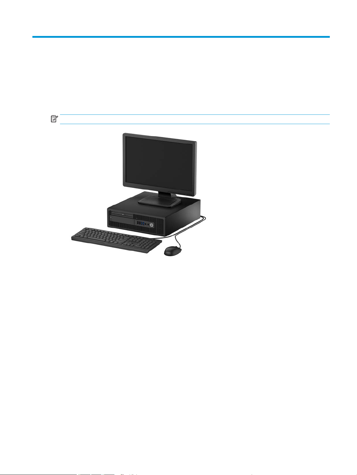
NOTE: This computer model can be used in a tower orientation or a desktop orientation.
Standard conguration features 1
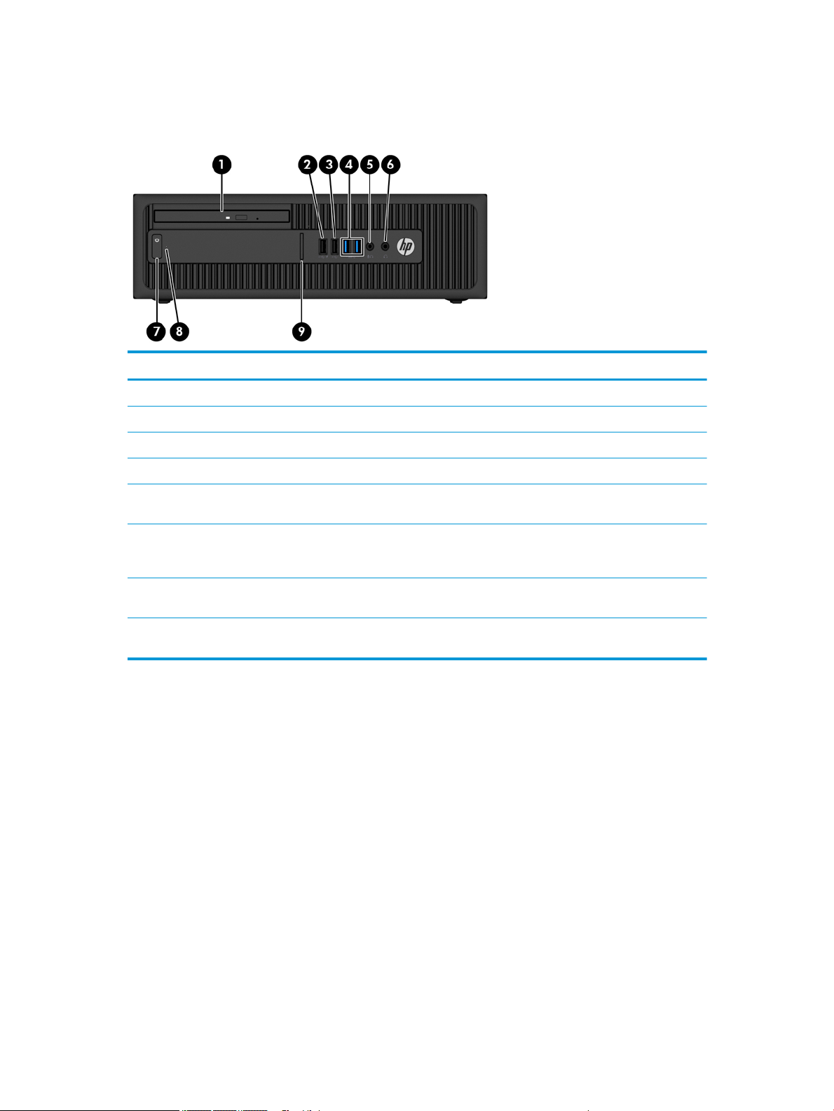
Front panel components
Drive conguration may vary by model. Some models have a bezel blank covering the slim optical drive bay.
Front panel components
1 Slim optical drive (optional) 6 Audio-out (headphone) jack
2 USB 2.0 charging (powered) port (black) 7 Power button
3 USB 2.0 port (black) 8 Hard drive activity light
4 USB 3.0 ports (blue) 9 SD card reader (optional)
5 Audio-out (headphone)/Audio-in (microphone) combo
jack
NOTE: When a device is plugged into the Audio-out (headphone)/Audio-in (microphone) combo jack, a dialog box will pop
up asking if you want to use the jack for a microphone or a headphone. You can recongure the jack at any time by doubleclicking the Audio Manager icon in the Windows® taskbar.
NOTE: The USB 2.0 charging port also provides current to charge a device such as a smart phone. The charging current is
available whenever the power cord is plugged into the system, even when the system is o.
NOTE: The Power On light is normally white when the power is on. If it is ashing red, there is a problem with the
computer and it is displaying a diagnostic code. Refer to the Maintenance and Service Guide to interpret the code.
2 Chapter 1 Product features
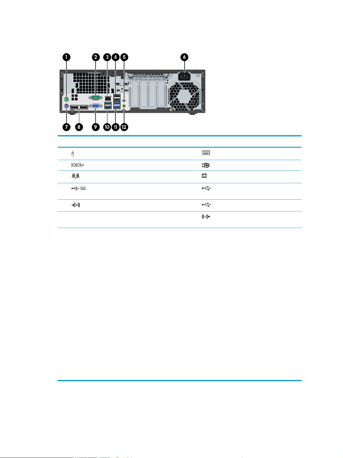
Rear panel components
Rear panel components
1 PS/2 mouse connector (green) 7 PS/2 keyboard connector (purple)
2 Serial port 8 DisplayPort monitor connectors
3 RJ-45 (network) jack 9 VGA monitor connector
4 USB 2.0 ports (black) with keyboard wakeup
function
5 Audio-in jack (blue) 11 USB SuperSpeed Plus ports (blue)*
6 Power cord connector 12 Audio-out jack for powered audio devices
NOTE: An optional second serial port and an optional parallel port are available from HP.
If using a USB keyboard, HP recommends connecting the keyboard to one of the USB 2.0 ports with the wakeup feature. The
wakeup feature is also supported on the PS/2 connector if enabled in BIOS F10 Setup.
When a device is plugged into the microphone/headphone jack, a dialog box will pop up asking if you want to use the jack for a
microphone or a headphone. You can recongure the jack at any time by double-clicking the Audio Manager icon in the
Windows taskbar.
When a graphics card is installed in one of the system board slots, the video connectors on the graphics card and/or the
integrated graphics on the system board may be used. The specic graphics card installed and software conguration will
determine the behavior.
The system board graphics can be disabled by changing settings in BIOS F10 Setup.
*USB SuperSpeed Plus port
Your product has two USB SuperSpeed Plus ports. This type of port, also called a USB 3.1 Gen 2 port, supports transfer speeds
up to 10 Gbps. For the best performance, follow these guidelines.
●
Use only USB SuperSpeed Plus-certied cables, 1 meter or less, with USB SuperSpeed Plus–certied devices.
●
Periodically inspect the electrical contacts of the cable and device for damage, dirt, or corrosion; replace cables that are
worn or damaged.
●
Route the USB SuperSpeed Plus cable away from other cables; do not bundle the cable with other cables.
●
Place the device and cable away from other high-powered products or products that may produce high electrical
radiation.
10 USB SuperSpeed ports (blue)
(green)
Rear panel components 3
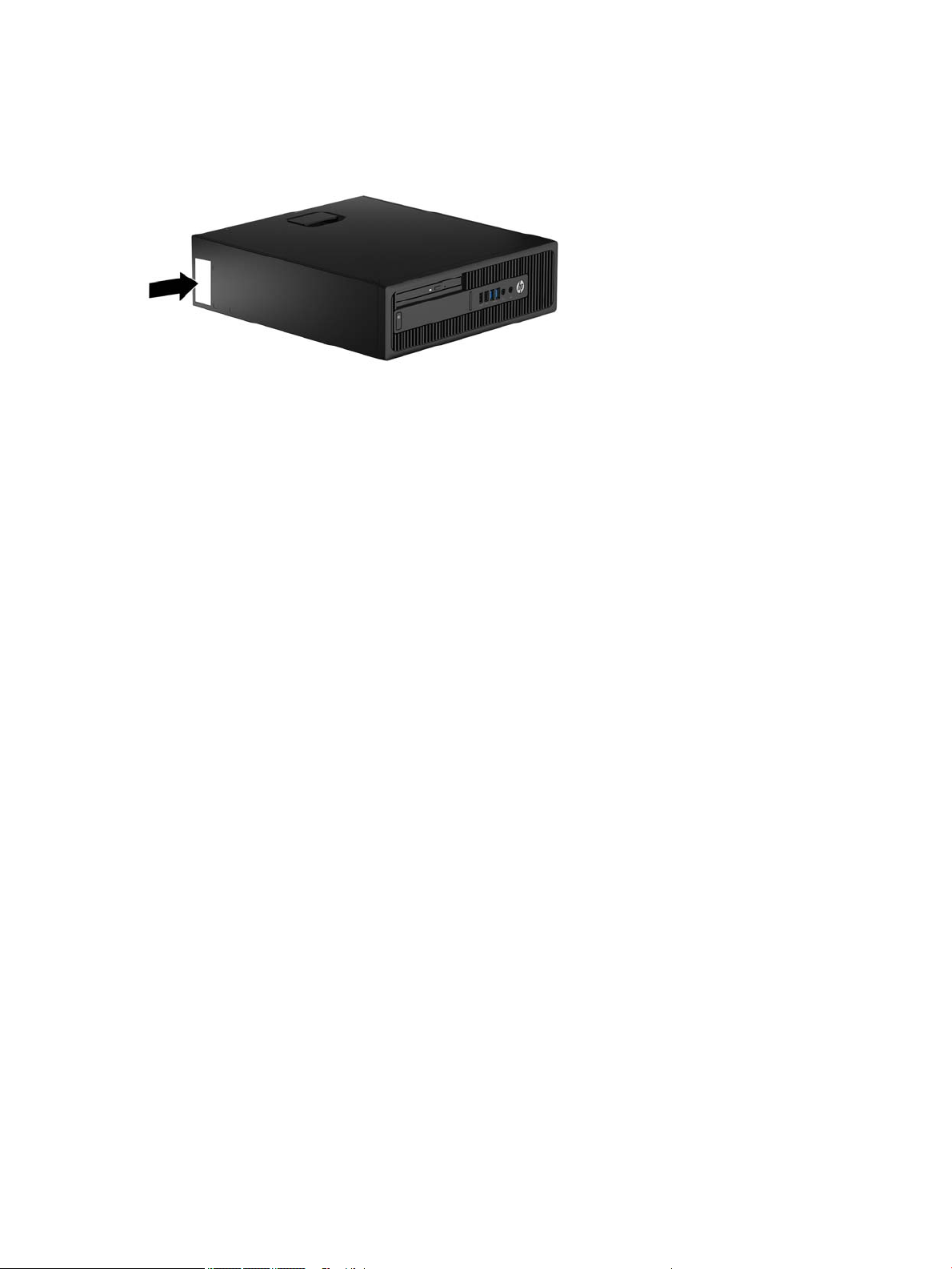
Serial number location
Each computer has a unique serial number and a product ID number that are located on the exterior of the
computer. Keep these numbers available for use when contacting customer service for assistance.
4 Chapter 1 Product features
2 Illustrated parts catalog
NOTE: HP continually improves and changes product parts. For complete and current information on
supported parts for your computer, go to http://partsurfer.hp.com, select your country or region, and then
follow the on-screen instructions.
Small Form Factor (SFF) chassis spare parts
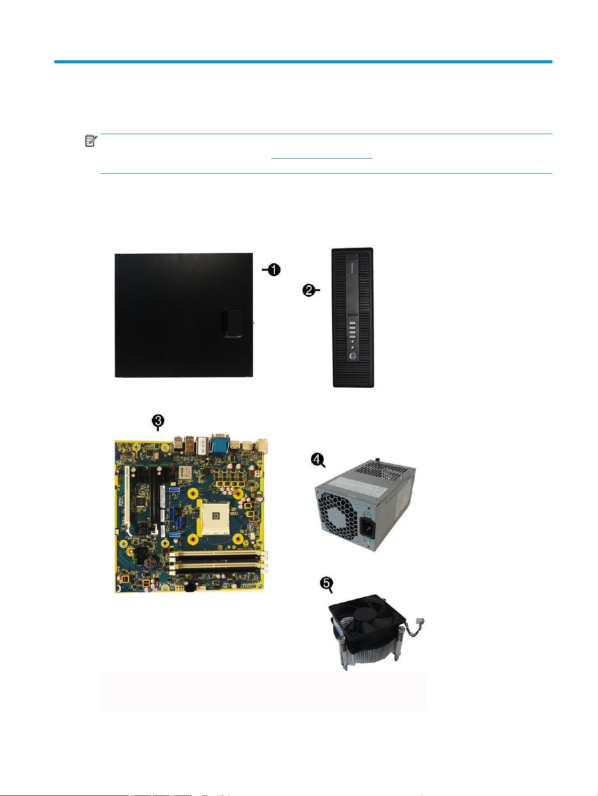
Computer major components
Small Form Factor (SFF) chassis spare parts 5

Item Description
(1) Access panel
(2) Front bezel
x
Bezel blank
(3) System board (includes replacement thermal material)
(4) Power supply
200W, 92% ecient
200W, 85% ecient
200W, standard
(5) Fan sink (includes replacement thermal material)
Memory modules (PC4-17000)
16-GB
8-GB
4-GB
2-GB
x
Processors (include replacement thermal material)
AMD A12-9800, 3.8 GHz
AMD A10-9700, 3.5 GHz
AMD A8-9700, 3.5 GHz
AMD A6-9600, 3.1 GHz
AMD A12-8870, 3.7 GHz
AMD A10-8770, 3.5 GHz
AMD A6-8570, 3.5 GHz
x
not illustrated
6 Chapter 2 Illustrated parts catalog
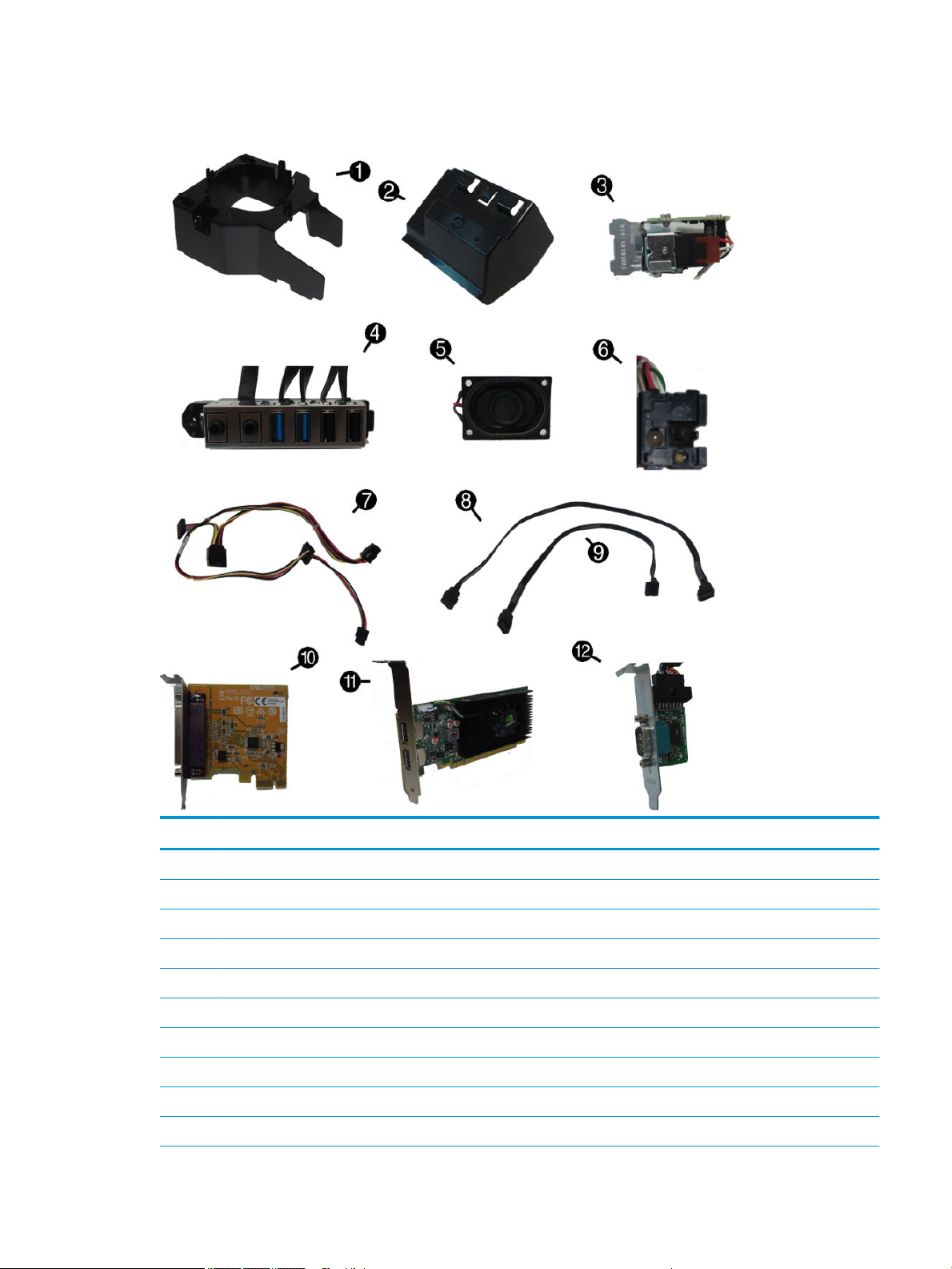
Misc parts
Item Description
(1) Fan bae
(2) Rear bae
(3) Solenoid lock
(4) Front I/O assembly
(5) Speaker
(6) Power switch
(7) SATA drive power cable
(8) SATA data cable, 19.5 inch, 2 straight ends
(9) SATA data cable, 14 inch, 1 straight end, 1 angled end
(10) Printer port, PCI card
Small Form Factor (SFF) chassis spare parts 7

Item Description
(11) nVIDIA GT730 2 GB DDR3 PCIex8
(12) Serial port, PCI card
x
WLAN modules
Intel Dual Band Wireless-AC 8260 + Bluetooth 4.0
Intel Dual Band Wireless-AC 3165 + Bluetooth 4.0
Intel Dual Band Wireless-AC 7265 NV
x
x
x
x
x
x
x
x
x
x
x
x
x
x
x
x
x
Front bezel dust lter
Chassis stand
Center strip kit
M.2 USB cable
Slim optical drive bezel blank
Slim optical drive latch
Hard drive conversion bracket, 2.5-inch to 3.5-inch
Hood sensor
HP Business PC Security Lock
Rubber foot
Secure Digital (SD) card reader
Keyed cable lock
Grommet, hard drive isolation, blue, for 3.5-inch hard drive
Grommet, hard drive isolation, blue, for 2.5-inch hard drive
DisplayPort cable
USB 3.1 Type Cx1 PCIe x1 card
PCIe to M.2 adapter
NOTE: M.2 solid-state drives are installed into an expansion slot using the PCIe to M.2 adapter
x
x
x
WLAN module expansion card adapter
Wireless antenna for use with WLAN modules
Adapters
DisplayPort to HDMI 1.4
DisplayPort to VGA
DisplayPort to DVI
x
Mouse
PS2, optical
USB, laser
USB, optical
8 Chapter 2 Illustrated parts catalog

Item Description
Antimicrobial (People’s Republic of China only)
Washable
Wireless (Brazil only)
HP USB Hardened
USB, gray
x
USB, gray
PS/2 slim
Antimicrobial
HP USB slim
HP USB Conferencing
Wireless keyboard, mouse, and dongle
USB/PS2 Washable
USB, Smart card
x
not illustrated
Keyboards
Misc boards
Description
nVIDIA GT730 2 GB DDR3 PCIex8
NVIDIA NVS 310 512MB DDR3 PCI Express Gen 2 x16 DisplayPort 1.2 Multi-Display Professional Graphics Board
Intel PRO/1000 NIC
Printer port
Serial port
USB 3.1 Type Cx1 PCIe x1 card
PCIe to M.2 adapter
NOTE: M.2 solid-state drives are installed into an expansion slot using the PCIe to M.2 adapter
WLAN module PCI adapter + Bluetooth
Small Form Factor (SFF) chassis spare parts 9

Drives
Description
Hard drives
2-TB, 7200-rpm
1-TB, 7200-rpm, 3.5-inch
1-TB, hybrid SSD, 5400-rpm, 2.5-inch
1-TB, hybrid SSD, 7200-rpm, 3.5-inch
500 GB, 7200 rpm, 3.5-inch
500-GB, 7200-rpm, 2.5-inch
500-GB, 7200-rpm, 2.5-inch, SED
500-GB, 5400-rpm, 2.5-inch, OPAL2, FIPS
500-GB, 5400-rpm, hybrid SSD, 2.5-inch
Solid-state drives, 2.5-inch
512 GB
512-GB, self-encrypting (SED), OPAL2, TLC
256 GB
256 GB (for use in Brazil)
256-GB, TLC
256-GB, OPAL2
240-GB, self-encrypting drive (SED), OPAL2, TLC
240-GB, TLC
128 GB
128 GB (for use in Brazil)
M.2 drives
NOTE: M.2 solid-state drives are installed into an expansion slot using the PCIe to M.2 adapter
512-GB, M.2, 2280SS, PCIe
512 GB, M.2, NVMe, TLC, PCIe
256-GB, M.2, 2280SS, PCIe
256-GB, M.2, NVMe, TLC, PCIe
Optical drives
DVD±RW drive
DVD-ROM drive
x
Grommet, hard drive isolation, blue, for 3.5-inch hard drive
Grommet, hard drive isolation, blue, for 2.5-inch hard drive
x
available after initial release -- contact your local HP Support team for details
10 Chapter 2 Illustrated parts catalog

3 Routine care, SATA drive guidelines, and
disassembly preparation
This chapter provides general service information for the computer. Adherence to the procedures and
precautions described in this chapter is essential for proper service.
CAUTION: When the computer is plugged into an AC power source, voltage is always applied to the system
board. You must disconnect the power cord from the power source before opening the computer to prevent
system board or component damage.
Electrostatic discharge information
A sudden discharge of static electricity from your nger or other conductor can destroy static-sensitive
devices or microcircuitry. Often the spark is neither felt nor heard, but damage occurs. An electronic device
exposed to electrostatic discharge (ESD) may not appear to be aected at all and can work perfectly
throughout a normal cycle. The device may function normally for a while, but it has been degraded in the
internal layers, reducing its life expectancy.
Networks built into many integrated circuits provide some protection, but in many cases, the discharge
contains enough power to alter device parameters or melt silicon junctions.
Generating static
The following table shows how humidity aects the electrostatic voltage levels generated by dierent
activities. A product can be degraded by 700 volts.
●
Dierent activities generate dierent amounts of static electricity.
●
Static electricity increases as humidity decreases.
Relative Humidity
Event 55% 40% 10%
Walking across carpet
Walking across vinyl oor
Motions of bench worker
Removing DIPs from plastic tube
Removing DIPs from vinyl tray
Removing DIPs from Styrofoam
Removing bubble pack from PCB
Packing PCBs in foam-lined box
7,500 V
3,000 V
400 V
400 V
2,000 V
3,500 V
7,000 V
5,000 V
15,000 V
5,000 V
800 V
700 V
4,000 V
5,000 V
20,000 V
11,000 V
35,000 V
12,000 V
6,000 V
2,000 V
11,500 V
14,500 V
26,500 V
21,000 V
Electrostatic discharge information 11

Preventing electrostatic damage to equipment
Many electronic components are sensitive to ESD. Circuitry design and structure determine the degree of
sensitivity. The following packaging and grounding precautions are necessary to prevent damage to electric
components and accessories.
●
To avoid hand contact, transport products in static-safe containers such as tubes, bags, or boxes.
●
Protect all electrostatic-sensitive parts and assemblies with conductive or approved containers or
packaging.
●
Keep electrostatic-sensitive parts in their containers until they arrive at static-free stations.
●
Place items on a grounded surface before removing them from their containers.
●
Always be properly grounded when touching a sensitive component or assembly.
●
Avoid contact with pins, leads, or circuitry.
●
Place reusable electrostatic-sensitive parts from assemblies in protective packaging or conductive
foam.
Personal grounding methods and equipment
Use the following equipment to prevent static electricity damage to equipment:
●
Wrist straps are exible straps with a maximum of one-megohm ± 10% resistance in the ground cords.
To provide proper ground, a strap must be worn snugly against bare skin. The ground cord must be
connected to the banana plug connector on the grounding mat or workstation and t snugly into it.
●
Heel straps/Toe straps/Boot straps can be used at standing workstations and are compatible with
most types of shoes or boots. On conductive oors or dissipative oor mats, use them on both feet with
a maximum of one-megohm ± 10% resistance between the operator and ground.
Static Shielding Protection Levels
Method Voltage
Antistatic plastic
Carbon-loaded plastic
Metallized laminate
Grounding the work area
To prevent static damage at the work area, observe the following precautions:
●
Cover the work surface with approved static-dissipative material. Provide a wrist strap connected to the
work surface and use properly grounded tools and equipment.
●
Use static-dissipative mats, foot straps, or air ionizers to give added protection.
●
Handle electrostatic-sensitive components, parts, and assemblies by the case or PCB laminate. Handle
them only at static-free work areas.
●
Turn o power and input signals before inserting and removing connectors or test equipment.
1,500
7,500
15,000
●
Use xtures made of static-safe materials when xtures must directly contact dissipative surfaces.
●
Keep work area free of nonconductive materials such as ordinary plastic assembly aids and Styrofoam.
●
Use eld service tools, such as cutters, screwdrivers, and vacuums, that are conductive.
12 Chapter 3 Routine care, SATA drive guidelines, and disassembly preparation

Recommended materials and equipment
The following grounding equipment is recommended to prevent electrostatic damage:
●
Antistatic tape
●
Antistatic smocks, aprons, or sleeve protectors
●
Conductive bins and other assembly or soldering aids
●
Conductive foam
●
Conductive tabletop workstations with ground cords of one-megohm +/- 10% resistance
●
Static-dissipative table or oor mats with hard ties to ground
●
Field service kits
●
Static awareness labels
●
Wrist straps and footwear straps providing one-megohm +/- 10% resistance
●
Material handling packages
●
Conductive plastic bags
●
Conductive plastic tubes
●
Conductive tote boxes
●
Opaque shielding bags
●
Transparent metallized shielding bags
●
Transparent shielding tubes
Operating guidelines
To prevent overheating and to help prolong the life of the computer:
●
Keep the computer away from excessive moisture, direct sunlight, and extremes of heat and cold.
●
Operate the computer on a sturdy, level surface. Leave a 10.2 cm (4-inch) clearance on all vented sides
of the computer and above the monitor to permit the required airow.
●
Never restrict the airow into the computer by blocking any vents or air intakes. Do not place the
keyboard, with the keyboard feet down, directly against the front of the desktop unit as this also
restricts airow.
●
Occasionally clean the air vents on all vented sides of the computer. Lint, dust, and other foreign matter
can block the vents and limit the airow. Be sure to unplug the computer before cleaning the air vents.
●
Never operate the computer with the cover or side panel removed.
●
Do not stack computers on top of each other or place computers so near each other that they are subject
to each other’s re-circulated or preheated air.
●
If the computer is to be operated within a separate enclosure, intake and exhaust ventilation must be
provided on the enclosure, and the same operating guidelines listed above will still apply.
●
Keep liquids away from the computer and keyboard.
Operating guidelines 13

●
Never cover the ventilation slots on the monitor with any type of material.
●
Install or enable power management functions of the operating system or other software, including
sleep states.
Routine care
General cleaning safety precautions
1. Never use solvents or ammable solutions to clean the computer.
2. Never immerse any parts in water or cleaning solutions; apply any liquids to a clean cloth and then use
the cloth on the component.
3. Always unplug the computer when cleaning with liquids or damp cloths.
4. Always unplug the computer before cleaning the keyboard, mouse, or air vents.
5. Disconnect the keyboard before cleaning it.
6. Wear safety glasses equipped with side shields when cleaning the keyboard.
Cleaning the computer case
Follow all safety precautions in General cleaning safety precautions on page 14 before cleaning the computer.
To clean the computer case, follow the procedures described below:
●
To remove light stains or dirt, use plain water with a clean, lint-free cloth or swab.
●
For stronger stains, use a mild dishwashing liquid diluted with water. Rinse well by wiping the surface
with a cloth or swab dampened with clear water.
●
For stubborn stains, use isopropyl (rubbing) alcohol. No rinsing is needed; alcohol will evaporate quickly
without leaving a residue.
●
After cleaning, always wipe the unit with a clean, lint-free cloth.
●
Occasionally clean the air vents on the computer. Lint and other foreign matter can block the vents and
limit the airow.
Cleaning the keyboard
Follow all safety precautions in General cleaning safety precautions on page 14 before cleaning the keyboard.
To clean the tops of the keys or the keyboard body, follow the procedures described in Cleaning the computer
case on page 14.
When cleaning debris from under the keys, review all rules in General cleaning safety precautions on page 14
before following these procedures:
CAUTION: Use safety glasses equipped with side shields before attempting to clean debris from under the
keys.
●
Visible debris underneath or between the keys may be removed by vacuuming or shaking.
●
Canned, pressurized air may be used to clean debris from under the keys. Caution should be used as too
much air pressure can dislodge lubricants applied under the wide keys.
14 Chapter 3 Routine care, SATA drive guidelines, and disassembly preparation

●
If you want to remove a key, use a specially designed key puller to prevent damage to the keys. This tool
is available through many electronics supply outlets.
CAUTION: Never remove a wide, level key (like the space bar) from the keyboard. If these keys are
improperly removed or installed, the keyboard may not function properly.
●
Cleaning under a key may be done with a swab moistened with isopropyl alcohol and then squeezed out.
Be careful not to wipe away lubricants necessary for proper key functions. Use tweezers to remove any
bers or dirt in conned areas. Allow the parts to air dry before reassembly.
Cleaning the monitor
●
Wipe the monitor screen with a towelette designed for cleaning monitors or with a clean cloth
moistened with water. Do not use sprays or aerosols directly on the screen; the liquid may seep into the
housing and damage a component. Never use solvents or ammable liquids on the monitor.
●
To clean the monitor body follow the procedures in Cleaning the computer case on page 14.
Cleaning the mouse
Before cleaning the mouse, ensure that the power to the computer is turned o.
●
Clean the mouse ball by rst removing the retaining plate and the ball from the housing. Pull out any
debris from the ball socket and wipe the ball with a clean, dry cloth before reassembly.
●
To clean the mouse body, follow the procedures in Cleaning the computer case on page 14.
Service considerations
Listed below are some of the considerations that you should keep in mind during the disassembly and
assembly of the computer.
Tools and software requirements
To service the computer, you need the following:
●
Torx T-15 screwdriver
●
Flat-bladed screwdriver (may sometimes be used in place of the Torx screwdriver)
●
Phillips #2 screwdriver
●
Diagnostics software
Screws
The screws used in the computer are not interchangeable. They may have standard or metric threads and may
be of dierent lengths. If an incorrect screw is used during the reassembly process, it can damage the unit. HP
strongly recommends that all screws removed during disassembly be kept with the part that was removed,
then returned to their proper locations.
CAUTION: Metric screws have a black nish. U.S. screws have a silver nish and are used on hard drives only.
CAUTION: As each subassembly is removed from the computer, it should be placed away from the work area
to prevent damage.
Service considerations 15

Cables and connectors
Most cables used throughout the unit are at, exible cables. These cables must be handled with care to
avoid damage. Apply only the tension required to seat or unseat the cables during insertion or removal from
the connector. Handle cables by the connector whenever possible. In all cases, avoid bending or twisting the
cables, and ensure that the cables are routed in such a way that they cannot be caught or snagged by parts
being removed or replaced.
CAUTION: When servicing this computer, ensure that cables are placed in their proper location during the
reassembly process. Improper cable placement can damage the computer.
Hard Drives
Handle hard drives as delicate, precision components, avoiding all physical shock and vibration. This applies
to failed drives as well as replacement spares.
●
If a drive must be mailed, place the drive in a bubble-pack mailer or other suitable protective packaging
and label the package “Fragile: Handle With Care.”
●
Do not remove hard drives from the shipping package for storage. Keep hard drives in their protective
packaging until they are actually mounted in the computer.
●
Avoid dropping drives from any height onto any surface.
●
If you are inserting or removing a hard drive, turn o the computer. Do not remove a hard drive while the
computer is on or in standby mode.
●
Before handling a drive, ensure that you are discharged of static electricity. While handling a drive, avoid
touching the connector.
●
Do not use excessive force when inserting a drive.
●
Avoid exposing a hard drive to liquids, temperature extremes, or products that have magnetic elds
such as monitors or speakers.
Lithium coin cell battery
The battery that comes with the computer provides power to the real-time clock and has a minimum lifetime
of about three years.
See the appropriate removal and replacement chapter for the chassis you are working on in this guide for
instructions on the replacement procedures.
WARNING! This computer contains a lithium battery. There is a risk of re and chemical burn if the battery is
handled improperly. Do not disassemble, crush, puncture, short external contacts, dispose in water or re, or
expose it to temperatures higher than 140ºF (60ºC). Do not attempt to recharge the battery.
NOTE: Batteries, battery packs, and accumulators should not be disposed of together with general
household waste. In order to forward them for recycling or proper disposal, please use the public collection
system or return them to HP.
16 Chapter 3 Routine care, SATA drive guidelines, and disassembly preparation

SATA hard drives
Serial ATA Hard Drive Characteristics
Number of pins/conductors in data cable 7/7
Number of pins in power cable 15
Maximum data cable length 39.37 in (100 cm)
Data interface voltage dierential 400-700 mV
Drive voltages 3.3 V, 5 V, 12 V
Jumpers for conguring drive N/A
Data transfer rate 6.0 Gb/s
SMART ATA drives
The Self Monitoring Analysis and Recording Technology (SMART) ATA drives for HP personal computers have
built-in drive failure prediction that warns the user or network administrator of an impending failure (crash)
of the hard drive. The SMART drive tracks fault prediction and failure indication parameters such as
reallocated sector count, spin retry count, and calibration retry count. If the drive determines that a failure is
imminent, it generates a fault alert.
SATA hard drives 17

4 Removal and replacement procedures –
small form factor (SFF) chassis
Adherence to the procedures and precautions described in this chapter is essential for proper service. After
completing all necessary removal and replacement procedures, run the Diagnostics utility to verify that all
components operate properly.
NOTE: Not all features listed in this guide are available on all computers.
NOTE: HP continually improves and changes product parts. For complete and current information on
supported parts for your computer, go to http://partsurfer.hp.com, select your country or region, and then
follow the on-screen instructions.
Preparation for disassembly
See Routine care, SATA drive guidelines, and disassembly preparation on page 11 for initial safety procedures.
1. Remove/disengage any security devices that prohibit opening the computer.
2. Close any open software applications.
3. Exit the operating system.
4. Remove any compact disc or media card from the computer.
5. Turn o the computer and any peripheral devices that are connected to it.
CAUTION: Turn o the computer before disconnecting any cables.
Regardless of the power-on state, voltage is always present on the system board as long as the system
is plugged into an active AC outlet. In some systems the cooling fan is on even when the computer is in
the “Standby,” or “Suspend” modes. The power cord should always be disconnected before servicing a
unit.
6. Disconnect the power cord from the electrical outlet and then from the computer.
7. Disconnect all peripheral device cables from the computer.
NOTE: During disassembly, label each cable as you remove it, noting its position and routing. Keep all
screws with the units removed.
CAUTION: The screws used in the computer are of dierent thread sizes and lengths; using the wrong
screw in an application may damage the unit.
8. If the computer is on a stand, remove the computer from the stand.
18 Chapter 4 Removal and replacement procedures – small form factor (SFF) chassis
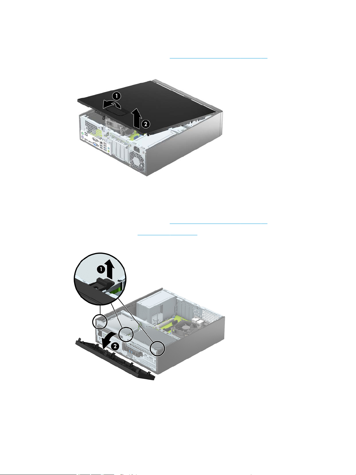
Access panel
1. Prepare the computer for disassembly (Preparation for disassembly on page 18).
2. Pull up the access panel handle (1), and then lift the panel o the computer (2).
To install the access panel, reverse the removal procedure.
Front bezel
1. Prepare the computer for disassembly (Preparation for disassembly on page 18).
2. Remove the access panel (Access panel on page 19).
3. Lift up the three tabs on the side of the bezel (1), and then rotate the bezel o the chassis (2).
To install the front bezel, reverse the removal procedure.
Access panel 19
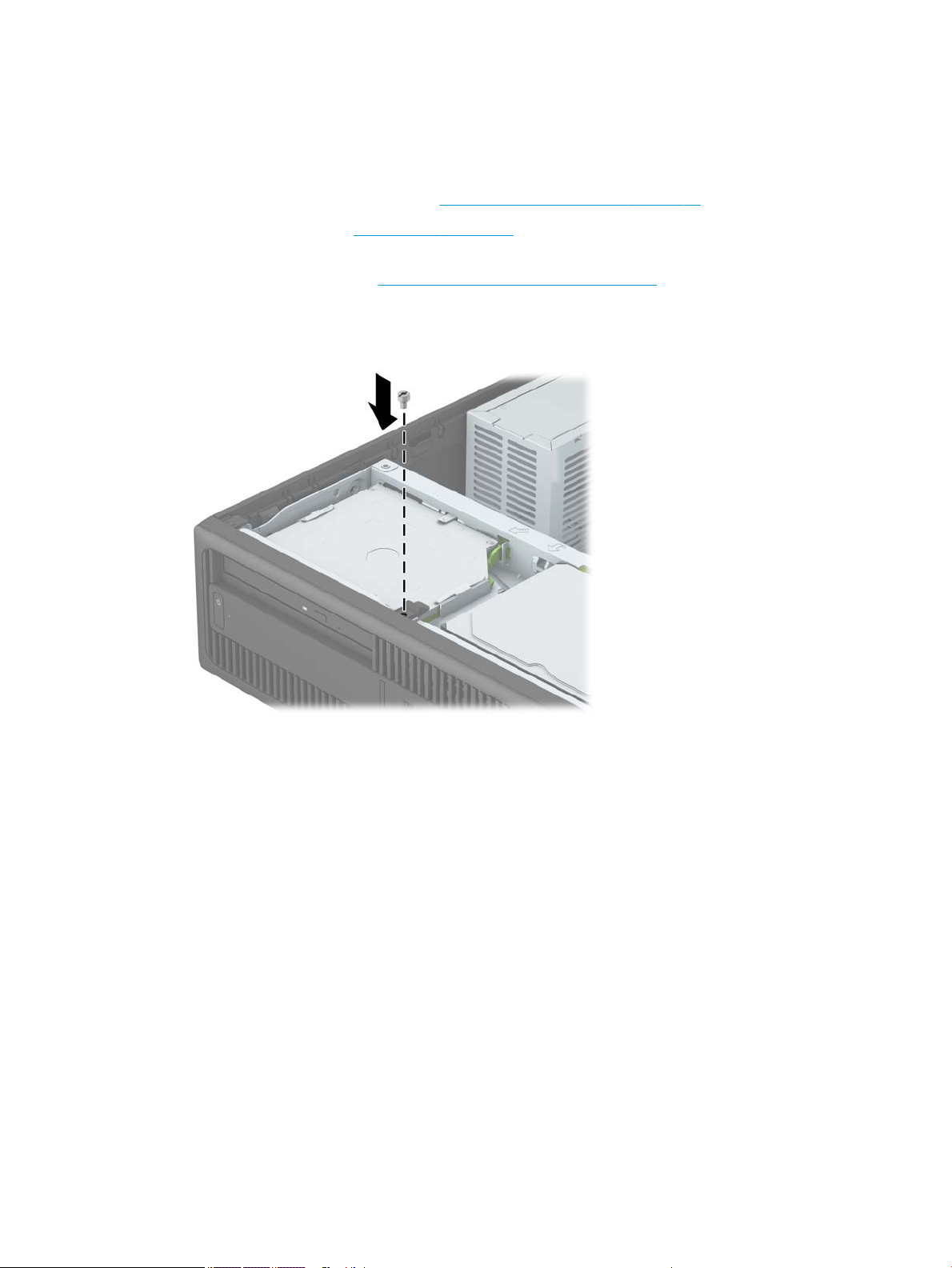
Front bezel security
The front bezel can be locked in place by installing a security screw provided by HP. To install the security
screw:
1. Prepare the computer for disassembly (Preparation for disassembly on page 18).
2. Remove the access panel (Access panel on page 19).
3. If you do not have a 6-32 standard screw, remove one of the four silver 6-32 standard screws located on
top of the drive cage. Refer to Installing and Removing Drives on page 33 for an illustration of the 6-32
standard screw locations.
4. Install the 6-32 security screw through the middle front bezel release tab to secure the front bezel in
place.
20 Chapter 4 Removal and replacement procedures – small form factor (SFF) chassis
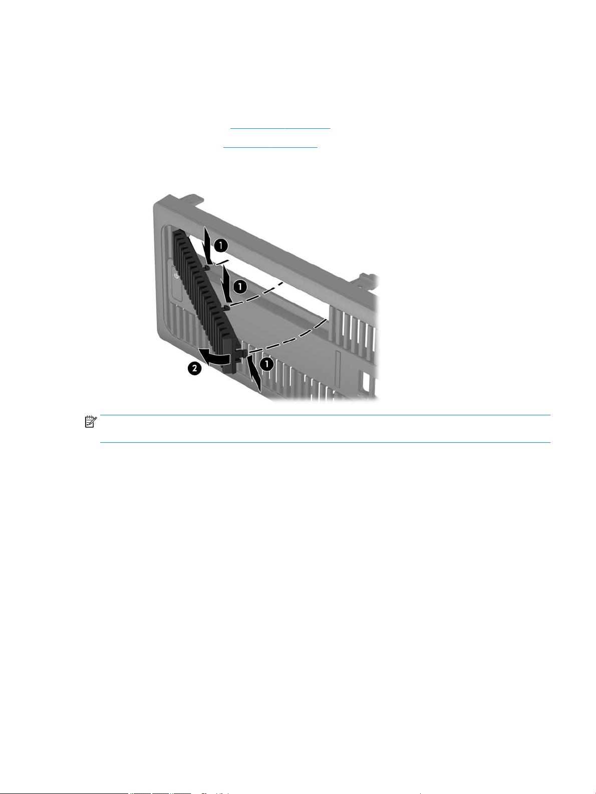
Slim optical drive bezel blank
On some models, there is a bezel blank covering the slim optical drive bay. Remove the bezel blank before
installing an optical drive. To remove the bezel blank:
1. Remove the access panel (Access panel on page 19).
2. Remove the front bezel (Front bezel on page 19).
3. To remove the slim optical drive bezel blank, press inward on the three retaining tabs that hold the bezel
blank in place (1), and then rotate the bezel blank o the front bezel (2).
NOTE: After removing the slim optical drive bezel blank and installing a slim optical drive, you can install an
optional bezel trim piece (available from HP) that surrounds the front of the slim optical drive.
Slim optical drive bezel blank 21
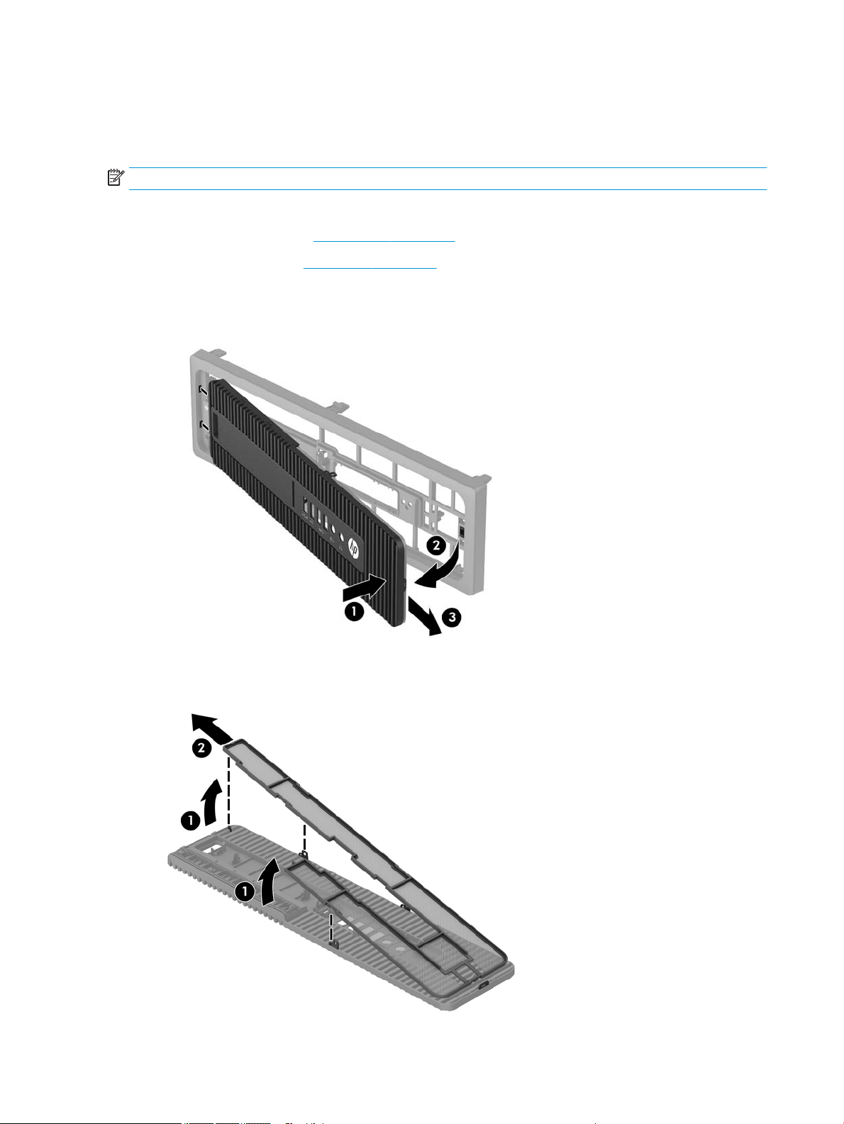
Dust lter
Some models are equipped with a front bezel that includes a dust lter. You must periodically clean the dust
lter so that the dust collected on the lter does not impede air ow through the computer.
NOTE: The optional dust lter front bezel is available from HP.
To clean the dust lter:
1. Remove the access panel (Access panel on page 19).
2. Remove the front bezel (Front bezel on page 19).
3. To remove the dust lter access panel, press the right side of the lter access panel on the main bezel
(1), rotate the right side of the lter access panel o the main bezel (2), and then pull the left side of the
lter access panel out of the main bezel (3).
4. To remove the dust lter, lift the two separated ends of the lter (1), and then pull the lter o the lter
access panel (2).
22 Chapter 4 Removal and replacement procedures – small form factor (SFF) chassis
Loading...