


 Loading...
Hardware Reference Guide
HP EliteDesk 800 G1 Tower
HP EliteDesk 800 G1 Small Form Factor HP EliteDesk 800 G1 Ultra-slim Desktop
© Copyright 2013 Hewlett-Packard Development Company, L.P. The information contained herein is subject to change without notice.
Microsoft® and Windows® are U.S. registered trademarks of Microsoft Corporation.
The only warranties for HP products and services are set forth in the express warranty statements accompanying such products and services. Nothing herein should be construed as constituting an additional warranty. HP shall not be liable for technical or editorial errors or omissions contained herein.
This document contains proprietary information that is protected by copyright. No part of this document may be photocopied, reproduced, or translated to another language without the prior written consent of Hewlett-Packard Company.
Hardware Reference Guide
HP EliteDesk 800 G1 Tower
HP EliteDesk 800 G1 Small Form Factor HP EliteDesk 800 G1 Ultra-slim Desktop First Edition (April 2013)
Document part number: 719014–001

About this book
This guide provides basic information for upgrading HP EliteDesk Business PCs.
WARNING! Text set off in this manner indicates that failure to follow directions could result in bodily harm or loss of life.
CAUTION: Text set off in this manner indicates that failure to follow directions could result in damage to equipment or loss of information.
 NOTE: Text set off in this manner provides important supplemental information.
ENWW |
iii |
iv About this book |
ENWW |

Table of contents
1 Product features ............................................................................................................................................. |
1 |
Standard configuration features ........................................................................................................... |
1 |
Tower (TWR) ....................................................................................................................... |
1 |
Small Form Factor (SFF) ..................................................................................................... |
2 |
Ultra-slim Desktop (USDT) .................................................................................................. |
2 |
Tower (TWR) front panel components ................................................................................................. |
3 |
Small Form Factor (SFF) front panel components ............................................................................... |
4 |
Ultra-slim Desktop (USDT) front panel components ............................................................................ |
5 |
Tower (TWR) rear panel components .................................................................................................. |
6 |
Small Form Factor (SFF) rear panel components ................................................................................ |
7 |
Ultra-slim Desktop (USDT) rear panel components ............................................................................. |
8 |
Media card reader components ............................................................................................................ |
9 |
Keyboard ............................................................................................................................................ |
10 |
Using the Windows logo key .............................................................................................. |
10 |
Serial number location ........................................................................................................................ |
12 |
Tower (TWR) ..................................................................................................................... |
12 |
Small Form Factor (SFF) ................................................................................................... |
12 |
Ultra-slim Desktop (USDT) ................................................................................................ |
13 |
2 Tower (TWR) hardware upgrades ................................................................................................................ |
14 |
Serviceability features ........................................................................................................................ |
14 |
Warnings and cautions ....................................................................................................................... |
14 |
Removing the computer access panel ............................................................................................... |
15 |
Replacing the computer access panel ............................................................................................... |
16 |
Removing the front bezel ................................................................................................................... |
17 |
Removing bezel blanks ...................................................................................................................... |
18 |
Replacing the front bezel .................................................................................................................... |
19 |
System board connections ................................................................................................................. |
20 |
Installing additional memory ............................................................................................................... |
21 |
DIMMs ............................................................................................................................... |
21 |
DDR3-SDRAM DIMMs ...................................................................................................... |
21 |
Populating DIMM sockets .................................................................................................. |
22 |
ENWW |
v |
Installing DIMMs ................................................................................................................ |
23 |
Removing or installing an expansion card .......................................................................................... |
25 |
Drive positions .................................................................................................................................... |
29 |
Installing and removing drives ............................................................................................................ |
30 |
Removing a 5.25-inch drive ............................................................................................... |
32 |
Installing a 5.25-inch drive ................................................................................................. |
33 |
Removing a 3.5-inch device .............................................................................................. |
36 |
Installing a 3.5-inch device ................................................................................................ |
38 |
Removing a slim optical drive ............................................................................................ |
40 |
Installing a slim optical drive .............................................................................................. |
41 |
Removing a 3.5-inch or 2.5-inch hard drive ....................................................................... |
44 |
Installing a 3.5-inch or 2.5-inch hard drive ......................................................................... |
45 |
Installing a security lock ..................................................................................................................... |
50 |
Cable lock .......................................................................................................................... |
50 |
Padlock .............................................................................................................................. |
50 |
HP business PC security lock ............................................................................................ |
51 |
Front bezel security ........................................................................................................... |
55 |
3 Small Form Factor (SFF) hardware upgrades ............................................................................................ |
57 |
Serviceability features ........................................................................................................................ |
57 |
Warnings and cautions ....................................................................................................................... |
57 |
Removing the computer access panel ............................................................................................... |
58 |
Replacing the computer access panel ............................................................................................... |
59 |
Removing the front bezel ................................................................................................................... |
60 |
Removing bezel blanks ...................................................................................................................... |
61 |
Replacing the front bezel .................................................................................................................... |
62 |
Changing from desktop to tower configuration ................................................................................... |
63 |
System board connections ................................................................................................................. |
64 |
Installing additional memory ............................................................................................................... |
65 |
DIMMs ............................................................................................................................... |
65 |
DDR3-SDRAM DIMMs ...................................................................................................... |
65 |
Populating DIMM sockets .................................................................................................. |
65 |
Installing DIMMs ................................................................................................................ |
66 |
Removing or installing an expansion card .......................................................................................... |
68 |
Drive positions .................................................................................................................................... |
72 |
Installing and removing drives ............................................................................................................ |
73 |
Removing a 3.5-inch device .............................................................................................. |
75 |
Installing a 3.5-inch device ................................................................................................ |
77 |
Removing a slim optical drive ............................................................................................ |
80 |
Installing a slim optical drive .............................................................................................. |
81 |
Removing and replacing a 3.5-inch hard drive .................................................................. |
82 |
vi |
ENWW |
Removing a 2.5-inch hard drive ......................................................................................... |
86 |
Installing a 2.5-inch hard drive ........................................................................................... |
88 |
Installing a security lock ..................................................................................................................... |
91 |
Cable lock .......................................................................................................................... |
91 |
Padlock .............................................................................................................................. |
91 |
HP business PC security lock ............................................................................................ |
92 |
Front bezel security ........................................................................................................... |
96 |
4 Ultra-slim Desktop (USDT) hardware upgrades ......................................................................................... |
98 |
Serviceability features ........................................................................................................................ |
98 |
Warnings and cautions ....................................................................................................................... |
98 |
Connecting the power cord ................................................................................................................ |
99 |
Removing the computer access panel ............................................................................................. |
100 |
Replacing the computer access panel ............................................................................................. |
101 |
Removing the front bezel ................................................................................................................. |
102 |
Removing a bezel blank ................................................................................................................... |
103 |
Replacing the front bezel .................................................................................................................. |
104 |
Changing from desktop to tower configuration ................................................................................. |
105 |
System board connections ............................................................................................................... |
106 |
Installing additional memory ............................................................................................................. |
107 |
SODIMMs ........................................................................................................................ |
107 |
DDR3-SDRAM SODIMMs ............................................................................................... |
107 |
Populating SODIMM sockets ........................................................................................... |
108 |
Installing SODIMMs ......................................................................................................... |
109 |
Replacing the optical drive ............................................................................................................... |
111 |
Removing the optical drive .............................................................................................. |
111 |
Preparing the new optical drive ....................................................................................... |
112 |
Installing the new optical drive ......................................................................................... |
113 |
Replacing the hard drive .................................................................................................................. |
114 |
Installing and removing a port cover ................................................................................................ |
118 |
Installing a security lock ................................................................................................................... |
119 |
Cable lock ........................................................................................................................ |
119 |
Padlock ............................................................................................................................ |
120 |
HP business PC security lock .......................................................................................... |
120 |
Front bezel security ......................................................................................................... |
124 |
Appendix A Battery replacement ................................................................................................................. |
126 |
Appendix B Unlocking the Smart Cover Lock ............................................................................................ |
129 |
Smart Cover FailSafe Key ................................................................................................................ |
129 |
ENWW |
vii |
Using the Smart Cover FailSafe Key to remove the Smart Cover Lock ........................................... |
130 |
Appendix C Electrostatic discharge ............................................................................................................ |
132 |
Preventing electrostatic damage ...................................................................................................... |
132 |
Grounding methods .......................................................................................................................... |
132 |
Appendix D Computer operating guidelines, routine care and shipping preparation ............................ |
133 |
Computer operating guidelines and routine care ............................................................................. |
133 |
Optical drive precautions .................................................................................................................. |
134 |
Operation ......................................................................................................................... |
134 |
Cleaning ........................................................................................................................... |
134 |
Safety ............................................................................................................................... |
134 |
Shipping preparation ........................................................................................................................ |
134 |
Index ................................................................................................................................................................. |
135 |
viii |
ENWW |

1 Product features
Standard configuration features
Features may vary depending on the model. For a complete listing of the hardware and software installed in the computer, run the diagnostic utility (included on some computer models only).
 NOTE: All three computer models can be used in a tower orientation or a desktop orientation.
Tower (TWR)
ENWW |
Standard configuration features 1 |

Small Form Factor (SFF)
Ultra-slim Desktop (USDT)
2 Chapter 1 Product features |
ENWW |
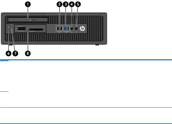
Tower (TWR) front panel components
Drive configuration may vary by model. Some models have a bezel blank covering one or more drive bays.
1 |
5.25-inch Half-Height Drive Bay (behind bezel) |
6 |
Hard Drive Activity Light |
|
|
|
|
|
|
2 |
USB 2.0 |
Ports (black) |
7 |
Slim Optical Drive (optional) |
|
|
|
|
|
3 |
USB 3.0 |
Ports (blue) |
8 |
3.5-inch Media Card Reader (optional) |
|
|
|
|
|
4 |
Headphone Connector |
9 |
Microphone/Headphone Connector |
|
|
|
|
|
|
5 |
Dual-State Power Button |
|
|
|
NOTE: When a device is plugged into the Microphone/Headphone Connector, a dialog box will pop up asking if you want to use the connector for a microphone Line-In device or a headphone. You can reconfigure the connector at any time by double-clicking the Audio Manager icon in the Windows taskbar.
NOTE: The Power On Light is normally white when the power is on. If it is flashing red, there is a problem with the computer and it is displaying a diagnostic code. Refer to the Maintenance and Service Guide to interpret the code.
ENWW |
Tower (TWR) front panel components 3 |
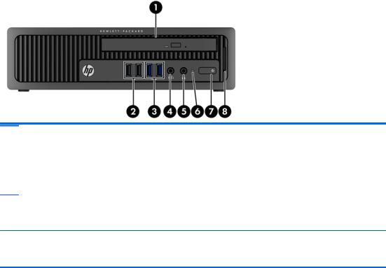
Small Form Factor (SFF) front panel components
Drive configuration may vary by model. Some models have a bezel blank covering one or more drive bays.
1 |
Slim Optical Drive (optional) |
5 |
Headphone Connector |
|
|
|
|
|
|
2 |
USB 2.0 |
Ports (black) |
6 |
Dual-State Power Button |
|
|
|
|
|
3 |
USB 3.0 |
Ports (blue) |
7 |
Hard Drive Activity Light |
|
|
|
|
|
4 |
Microphone/Headphone Connector |
8 |
3.5-inch Media Card Reader (optional) |
|
NOTE: When a device is plugged into the Microphone/Headphone Connector, a dialog box will pop up asking if you want to use the connector for a microphone Line-In device or a headphone. You can reconfigure the connector at any time by double-clicking the Audio Manager icon in the Windows taskbar.
NOTE: The Power On Light is normally white when the power is on. If it is flashing red, there is a problem with the computer and it is displaying a diagnostic code. Refer to the Maintenance and Service Guide to interpret the code.
4 Chapter 1 Product features |
ENWW |
Ultra-slim Desktop (USDT) front panel components
Drive configuration may vary by model. Some models have a bezel blank covering the optical drive bay.
1 |
Slim Optical Drive (optional) |
5 |
Headphone Connector |
|
|
|
|
|
|
2 |
USB 2.0 |
Ports (black) |
6 |
Hard Drive Activity Light |
|
|
|
|
|
3 |
USB 3.0 |
Ports (blue) |
7 |
Dual-State Power Button |
|
|
|
|
|
4 |
Microphone/Headphone Connector |
8 |
SD Media Card Reader (optional) |
|
NOTE: When a device is plugged into the Microphone/Headphone Connector, a dialog box will pop up asking if you want to use the connector for a microphone Line-In device or a headphone. You can reconfigure the connector at any time by double-clicking the Audio Manager icon in the Windows taskbar.
NOTE: The Power On Light is normally white when the power is on. If it is flashing red, there is a problem with the computer and it is displaying a diagnostic code. Refer to the Maintenance and Service Guide to interpret the code.
ENWW |
Ultra-slim Desktop (USDT) front panel components |
5 |

Tower (TWR) rear panel components
1 |
Power Cord Connector |
7 |
Line-Out Connector for powered audio |
|
|
|
devices (green) |
|
|
|
|
2 |
PS/2 Keyboard Connector (purple) |
8 |
PS/2 Mouse Connector (green) |
|
|
|
|
3 |
USB 2.0 Ports (black) |
9 |
RJ-45 Network Connector |
|
|
|
|
4 |
DisplayPort Monitor Connectors |
10 |
Serial Connector |
|
|
|
|
5 |
VGA Monitor Connector |
11 |
Line-In Audio Connector (blue) |
|
|
|
|
6 |
USB 3.0 Ports (blue) |
|
|
NOTE: An optional second serial port and an optional parallel port are available from HP.
When a device is plugged into the blue Line-In Audio Connector, a dialog box will pop up asking if you want to use the connector for a line-in device or a microphone. You can reconfigure the connector at any time by doubleclicking the Audio Manager icon in the Windows taskbar.
When a graphics card is installed in one of the system board slots, the video connectors on the graphics card and the integrated graphics on the system board may be used at the same time. However, for such a configuration, only the display connected to the discrete graphics card will display POST messages.
The system board graphics can be disabled by changing settings in Computer Setup.
6 Chapter 1 Product features |
ENWW |

Small Form Factor (SFF) rear panel components
1 |
PS/2 Mouse Connector (green) |
7 |
PS/2 Keyboard Connector (purple) |
|
|
|
|
2 |
RJ-45 Network Connector |
8 |
DisplayPort Monitor Connectors |
|
|
|
|
3 |
Serial Connector |
9 |
VGA Monitor Connector |
|
|
|
|
4 |
USB 2.0 Ports (black) |
10 |
USB 3.0 Ports (blue) |
|
|
|
|
5 |
Line-In Audio Connector (blue) |
11 |
Line-Out Connector for powered audio |
|
|
|
devices (green) |
|
|
|
|
6 |
Power Cord Connector |
|
|
NOTE: An optional second serial port and an optional parallel port are available from HP.
When a device is plugged into the blue Line-In Audio Connector, a dialog box will pop up asking if you want to use the connector for a line-in device or a microphone. You can reconfigure the connector at any time by doubleclicking the Audio Manager icon in the Windows taskbar.
When a graphics card is installed in one of the system board slots, the video connectors on the graphics card and the integrated graphics on the system board may be used at the same time. However, for such a configuration, only the display connected to the discrete graphics card will display POST messages.
The system board graphics can be disabled by changing settings in Computer Setup.
ENWW |
Small Form Factor (SFF) rear panel components |
7 |

Ultra-slim Desktop (USDT) rear panel components
1 |
Line-Out Connector for powered audio |
6 |
VGA Monitor Connector |
|
|
devices (green) |
|
|
|
|
|
|
|
|
2 |
USB 2.0 |
Ports (black) |
7 |
Power Cord Connector |
|
|
|
|
|
3 |
USB 3.0 |
Ports (blue) |
8 |
Line-In Audio Connector (blue) |
|
|
|
|
|
4 |
DisplayPort Monitor Connectors |
9 |
RJ-45 Network Connector |
|
|
|
|
|
|
5 |
PS/2 Keyboard Connector (purple) |
10 |
PS/2 Mouse Connector (green) |
|
NOTE: When a device is plugged into the blue Line-In Audio Connector, a dialog box will pop up asking if you want to use the connector for a line-in device or a microphone. You can reconfigure the connector at any time by double-clicking the Audio Manager icon in the Windows taskbar.
If an MXM graphics card is installed, all of the video connectors may be used at the same time. However, for such a configuration, only the display connected to the upper DisplayPort will display POST messages.
The system board graphics can be disabled by changing settings in Computer Setup.
8 Chapter 1 Product features |
ENWW |

Media card reader components
The media card reader is an optional device available on some models only. Refer to the following illustration and table to identify the media card reader components.
No. |
Slot |
Media |
|
|
|
|
|
|
|
1 |
SD/HC/XC/UHS-1/Plus |
● Secure Digital (SD) |
● Secure Digital High |
● Secure Digital |
|
|
|
Capacity (SDHC) |
Extended Capacity |
|
|
|
|
Memory Card |
|
|
|
|
(SDXC) |
2Media Card Reader Activity Light
3 |
CompactFlash I/II |
● |
CompactFlash Card |
● |
CompactFlash Card |
● |
MicroDrive |
|
|
|
Type 1 |
|
Type 2 |
|
|
|
|
|
|
|
|
|
|
4 |
MS PRO/MS PRO Duo |
● |
Memory Stick (MS) |
● |
Memory Stick |
● |
Memory Stick |
|
|
● |
Memory Stick Select |
|
MagicGate |
|
MagicGate Duo |
|
|
● |
Memory Stick Duo |
● |
Memory Stick PRO- |
||
|
|
● |
Memory Stick PRO |
||||
|
|
|
(MS Duo) |
|
HG Duo |
||
|
|
|
(MS PRO) |
● |
Memory Stick PRO |
|
|
|
|
|
|
|
|
||
|
|
|
|
|
Duo (MS PRO Duo) |
|
|
|
|
|
|
|
|
|
|
ENWW |
Media card reader components 9 |

Keyboard
Component |
Component |
||
|
|
|
|
1 |
Sleep |
6 |
Mute volume |
|
|
|
|
2 |
Fast reverse |
7 |
Decrease volume |
|
|
|
|
3 |
Play/pause |
8 |
Increase volume |
|
|
|
|
4 |
Stop |
9 |
Windows logo key |
|
|
|
|
5 |
Fast forward |
10 |
Function |
|
|
|
|
Using the Windows logo key
Use the Windows Logo key in combination with other keys to perform certain functions available in the Windows operating system.
Windows Logo Key + |
Windows 7 |
Windows 8 |
|
|
|
no other key |
Displays the Start menu |
Displays the Start screen |
|
|
|
c |
|
Opens charms |
|
|
|
d |
Displays the Desktop |
Displays the Desktop |
|
|
|
e |
Launches My Computer |
Opens Windows Explorer |
|
|
|
f |
Launches Find Document |
Goes to files in Search charm |
|
|
|
Ctrl + f |
Launches Find Computer |
Launches Find Computer |
|
|
|
g |
Cycles through gadgets |
Cycles through gadgets |
|
|
|
h |
|
Goes to Share charm |
|
|
|
i |
|
Goes to Settings charm |
|
|
|
k |
|
Goes to Devices charm |
|
|
|
10 Chapter 1 Product features |
ENWW |

Windows Logo Key + Windows 7 |
Windows 8 |
l |
Locks the computer if you are connected to |
|
a network domain, or allows you to switch |
|
users if you are not connected to a network |
|
domain |
Locks the computer if you are connected to a network domain, or allows you to switch users if you are not connected to a network domain
m |
Minimizes all open applications |
Minimizes all open applications |
|
|
|
o |
|
Locks screen orientation |
|
|
|
p |
Choose a presentation display mode |
Opens projection options |
|
|
|
q |
|
Goes to Search charm |
|
|
|
r |
Launches the Run dialog box |
Launches the Run dialog box |
|
|
|
t |
Cycles through programs on the taskbar |
Cycles through programs on the taskbar |
|
|
|
u |
Launches Ease of Access Center |
Launches Ease of Access Center |
|
|
|
v |
|
Cycles through notifications |
|
|
|
w |
|
Goes to Settings in Search charm |
|
|
|
x |
Opens Windows Mobility Center if present |
Opens Windows Mobility Center if present |
|
|
|
z |
|
Opens applications bar |
|
|
|
F1 |
Launches Windows Help |
Launches Windows Help |
|
|
|
Tab |
Cycles through programs on the Taskbar |
Cycles through metro application history |
|
using the Windows Flip 3-D |
|
|
|
|
Ctrl + Tab |
Use the arrow keys to cycle through |
Use the arrow keys to cycle through metro |
|
programs on the Taskbar by using Windows |
application history |
|
Flip 3-D |
|
|
|
|
Spacebar |
Brings all gadgets to the front and select |
Switches input language and keyboard |
|
Windows Sidebar |
layout |
|
|
|
any number key |
Goes to the application at the given position |
Goes to the application at the given position |
|
on the taskbar |
on the taskbar |
|
|
|
up arrow |
Maximizes the window |
Maximizes the desktop window |
|
|
|
left arrow |
Snaps the window to the left side of the |
Snaps the desktop window to the left side of |
|
screen |
the screen |
|
|
|
right arrow |
Snaps the window to the right side of the |
Snaps the desktop window to the right side |
|
screen |
of the screen |
|
|
|
down arrow |
Minimizes the window |
Minimizes the desktop window |
|
|
|
Shift + left arrow or right |
Moves a window from one monitor to |
Moves a window from one monitor to |
arrow |
another |
another |
|
|
|
, (comma) |
|
Peeks at the desktop |
|
|
|
. (period) |
|
Snap a metro application to the right |
|
|
|
Shift + . (period) |
|
Snap a metro application to the left |
|
|
|
Enter |
|
Launches Narrator |
|
|
|
Esc |
|
Exits Magnifier |
|
|
|
+ (on numpad) |
Zooms in |
Zooms in (Magnifier) |
|
|
|
ENWW |
Keyboard 11 |
Windows Logo Key + |
Windows 7 |
Windows 8 |
|
|
|
- (on numpad) |
Zooms out |
Zooms out (Magnifier) |
|
|
|
Home |
Minimizes non-active desktop windows |
Minimizes non-active desktop windows |
|
|
|
Break |
Displays System Properties |
Displays System Properties |
|
|
|
PgUp |
|
Moves Start screen to left monitor |
|
|
|
PgDn |
|
Moves Start screen to right monitor |
|
|
|
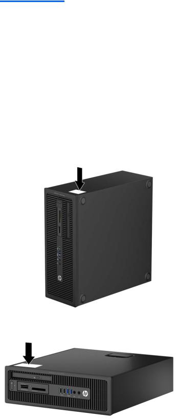
Serial number location
Each computer has a unique serial number and a product ID number that are located on the exterior of the computer. Keep these numbers available for use when contacting customer service for assistance.
Tower (TWR)
Small Form Factor (SFF)
12 Chapter 1 Product features |
ENWW |
Ultra-slim Desktop (USDT)
ENWW |
Serial number location 13 |

2 Tower (TWR) hardware upgrades
Serviceability features
The computer includes features that make it easy to upgrade and service. No tools are needed for most of the installation procedures described in this chapter.
Warnings and cautions
Before performing upgrades be sure to carefully read all of the applicable instructions, cautions, and warnings in this guide.
 WARNING! To reduce the risk of personal injury from electrical shock, hot surfaces, or fire:
Disconnect the power cord from the wall outlet and allow the internal system components to cool before touching.
Do not plug telecommunications or telephone connectors into the network interface controller (NIC) receptacles.
Do not disable the power cord grounding plug. The grounding plug is an important safety feature.
Plug the power cord in a grounded (earthed) outlet that is easily accessible at all times.
To reduce the risk of serious injury, read the Safety & Comfort Guide. It describes proper workstation, setup, posture, and health and work habits for computer users, and provides important electrical and mechanical safety information. This guide is located on the Web at http://www.hp.com/ergo.
 WARNING! Energized and moving parts inside.
Disconnect power to the equipment before removing the enclosure.
Replace and secure the enclosure before re-energizing the equipment.
CAUTION: Static electricity can damage the electrical components of the computer or optional equipment. Before beginning these procedures, ensure that you are discharged of static electricity by briefly touching a grounded metal object. See Electrostatic discharge on page 132 for more information.
When the computer is plugged into an AC power source, voltage is always applied to the system board. You must disconnect the power cord from the power source before opening the computer to prevent damage to internal components.
14 Chapter 2 Tower (TWR) hardware upgrades |
ENWW |

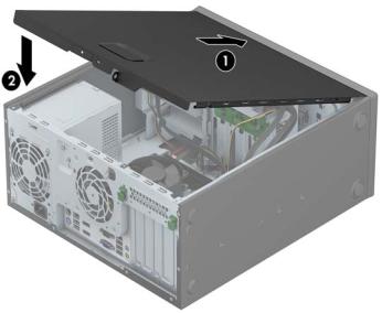
Removing the computer access panel
To access internal components, you must remove the access panel:
1.Remove/disengage any security devices that prohibit opening the computer.
2.Remove all removable media, such as compact discs or USB flash drives, from the computer.
3.Turn off the computer properly through the operating system, then turn off any external devices.
4.Disconnect the power cord from the power outlet and disconnect any external devices.
 CAUTION: Regardless of the power-on state, voltage is always present on the system board as long as the system is plugged into an active AC outlet. You must disconnect the power cord to avoid damage to the internal components of the computer.
5.Lift up on the access panel handle (1) then lift the access panel off the computer (2).
ENWW |
Removing the computer access panel 15 |
Replacing the computer access panel
Slide the lip on the front end of the access panel under the lip on the front of the chassis (1) then press the back end of the access panel onto the unit so that it locks into place (2).
16 Chapter 2 Tower (TWR) hardware upgrades |
ENWW |
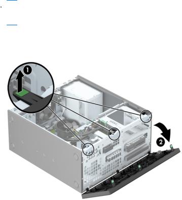
Removing the front bezel
1.Remove/disengage any security devices that prohibit opening the computer.
2.Remove all removable media, such as compact discs or USB flash drives, from the computer.
3.Turn off the computer properly through the operating system, then turn off any external devices.
4.Disconnect the power cord from the power outlet and disconnect any external devices.
 CAUTION: Regardless of the power-on state, voltage is always present on the system board as long as the system is plugged into an active AC outlet. You must disconnect the power cord to avoid damage to the internal components of the computer.
5.Remove the computer access panel.
6.Lift up the three tabs on the side of the bezel (1), then rotate the bezel off the chassis (2).
ENWW |
Removing the front bezel 17 |
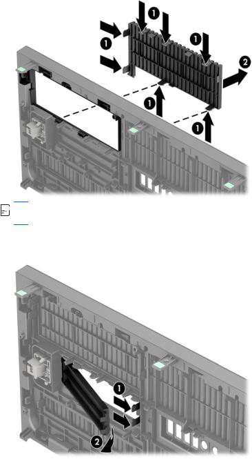
Removing bezel blanks
On some models, there are bezel blanks covering one or more drive bays that need to be removed before installing a drive. To remove a bezel blank:
1.Remove the access panel and front bezel.
2.Remove the bezel blank for the appropriate drive:
●To remove a 5.25-inch bezel blank, press inward on the retaining tabs that hold the bezel blank in place (1) then pull the bezel blank from the front bezel (2).


 NOTE: After removing the 5.25-inch drive bezel blank and installing a drive, you can install an optional bezel trim piece (available from HP) that surrounds the front of the drive.
●To remove a 3.5-inch bezel blank, press outward on the two retaining tabs that hold the bezel blank in place (1) and rotate the bezel blank back and to the right to remove it (2).
18 Chapter 2 Tower (TWR) hardware upgrades |
ENWW |

●To remove a slim optical drive bezel blank, press inward on the retaining tabs that hold the bezel blank in place (1) then pull the bezel blank from the front bezel (2).


 NOTE: After removing the slim optical drive bezel blank and installing a slim optical drive, you can install an optional bezel trim piece (available from HP) that surrounds the front of the slim optical drive.
Replacing the front bezel
Insert the three hooks on the bottom side of the bezel into the rectangular holes on the chassis (1) then rotate the top side of the bezel onto the chassis (2) and snap it into place.
ENWW |
Replacing the front bezel 19 |
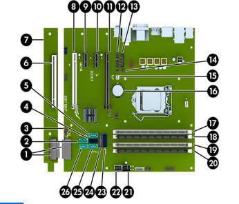
System board connections
Refer to the following illustration and table to identify the system board connectors.
No. |
System Board Connector |
System Board Label |
Color |
Component |
|
|
|
|
|
1 |
System Board PCI Extender |
EXT |
black |
System Board PCI Extender |
|
Connectors |
|
|
(optional, shown installed) |
|
|
|
|
|
2 |
SATA 3.0 |
SATA1 |
light blue |
Any SATA Device other than the |
|
|
|
|
Primary Hard Drive |
|
|
|
|
|
3 |
USB 2.0 |
MEDIA |
black |
USB 2.0 Device, such as a USB 2.0 |
|
|
|
|
Media Card Reader |
|
|
|
|
|
4 |
SATA 3.0 |
SATA0 |
dark blue |
Primary Hard Drive |
|
|
|
|
|
5 |
SATA 3.0 |
SATA2 |
light blue |
Any SATA Device other than the |
|
|
|
|
Primary Hard Drive |
|
|
|
|
|
6 |
PCI (optional) |
PCI1 |
white |
Expansion Card |
|
|
|
|
|
7 |
System Board PCI Extender |
(not applicable) |
(not |
Expansion Card |
|
(optional) |
|
applicable) |
|
|
|
|
|
|
8 |
PCI Express x16 downshifted |
X4PCIEXP |
white |
Expansion Card |
|
to a x4 |
|
|
|
|
|
|
|
|
9 |
PCI Express x1 |
X1PCIEXP2 |
black |
Expansion Card |
|
|
|
|
|
10 |
PCI Express x1 |
X1PCIEXP1 |
black |
Expansion Card |
|
|
|
|
|
11 |
PCI Express x16 |
X16PCIEXP |
black |
Expansion Card |
|
|
|
|
|
12 |
Parallel Port |
PAR |
black |
Parallel Port |
|
|
|
|
|
13 |
Serial Port |
COMB |
black |
Serial Port |
|
|
|
|
|
14 |
Hood Lock |
HLCK |
black |
Hood Lock |
|
|
|
|
|
15 |
Hood Sensor |
HSENSE |
white |
Hood Sensor |
|
|
|
|
|
16 |
Battery |
BAT |
black |
Battery |
|
|
|
|
|
20 Chapter 2 Tower (TWR) hardware upgrades |
ENWW |

No. |
System Board Connector |
System Board Label |
Color |
Component |
|
|
|
|
|
17 |
DIMM4 (Channel A) |
DIMM4 |
white |
Memory Module |
|
|
|
|
|
18 |
DIMM3 (Channel A) |
DIMM3 |
black |
Memory Module |
|
|
|
|
|
19 |
DIMM2 (Channel B) |
DIMM2 |
white |
Memory Module |
|
|
|
|
|
20 |
DIMM1 (Channel B) |
DIMM1 |
black |
Memory Module |
|
|
|
|
|
21 |
Power |
SATA PWR0 |
black |
SATA Drives |
|
|
|
|
|
22 |
Power |
PWR |
white |
System Board |
|
|
|
|
|
23 |
USB 3.0 |
FRONT USB3.0 |
blue |
Front USB 3.0 Ports |
|
|
|
|
|
24 |
USB 3.0 |
MEDIA3.0 |
black |
USB 3.0 Device, such as a USB 3.0 |
|
|
|
|
Media Card Reader |
|
|
|
|
|
25 |
SATA 3.0 |
SATA3 |
light blue |
Any SATA Device other than the |
|
|
|
|
Primary Hard Drive |
|
|
|
|
|
26 |
SATA 3.0 |
SATA5 |
light blue |
Any SATA Device other than the |
|
|
|
|
Primary Hard Drive |
|
|
|
|
|
Installing additional memory
The computer comes with double data rate 3 synchronous dynamic random access memory (DDR3SDRAM) dual inline memory modules (DIMMs).
DIMMs
The memory sockets on the system board can be populated with up to four industry-standard DIMMs. These memory sockets are populated with at least one preinstalled DIMM. To achieve the maximum memory support, you can populate the system board with up to 32-GB of memory configured in a high-performing dual channel mode.
DDR3-SDRAM DIMMs
For proper system operation, the DDR3-SDRAM DIMMs must be:
●industry-standard 240-pin
●unbuffered non-ECC PC3-12800 DDR3-1600 MHz-compliant
●1.35 volt or 1.5 volt DDR3/DDR3L-SDRAM DIMMs
The DDR3-SDRAM DIMMs must also:
●support CAS latency 11 DDR3 1600 MHz (11-11-11 timing)
●contain the mandatory JEDEC SPD information
ENWW |
Installing additional memory 21 |

In addition, the computer supports:
●512-Mbit, 1-Gbit, and 2-Gbit non-ECC memory technologies
●single-sided and double-sided DIMMs
●DIMMs constructed with x8 and x16 DDR devices; DIMMs constructed with x4 SDRAM are not supported
 NOTE: The system will not operate properly if you install unsupported DIMMs.
Populating DIMM sockets
There are four DIMM sockets on the system board, with two sockets per channel. The sockets are labeled DIMM1, DIMM2, DIMM3, and DIMM4. Sockets DIMM1 and DIMM2 operate in memory channel B. Sockets DIMM3 and DIMM4 operate in memory channel A.
The system will automatically operate in single channel mode, dual channel mode, or flex mode, depending on how the DIMMs are installed.


 NOTE: Single channel and unbalanced dual channel memory configurations will result in inferior graphics performance.
●The system will operate in single channel mode if the DIMM sockets are populated in one channel only.
●The system will operate in a higher-performing dual channel mode if the total memory capacity of the DIMMs in Channel A is equal to the total memory capacity of the DIMMs in Channel B. The technology and device width can vary between the channels. For example, if Channel A is populated with two 1-GB DIMMs and Channel B is populated with one 2-GB DIMM, the system will operate in dual channel mode.
●The system will operate in flex mode if the total memory capacity of the DIMMs in Channel A is not equal to the total memory capacity of the DIMMs in Channel B. In flex mode, the channel populated with the least amount of memory describes the total amount of memory assigned to dual channel and the remainder is assigned to single channel. For optimal speed, the channels should be balanced so that the largest amount of memory is spread between the two channels. If one channel will have more memory than the other, the larger amount should be assigned to Channel A. For example, if you are populating the sockets with one 2-GB DIMM, and three 1-GB DIMMs, Channel A should be populated with the 2-GB DIMM and one 1-GB DIMM, and Channel B should be populated with the other two 1-GB DIMMs. With this configuration, 4-GB will run as dual channel and 1-GB will run as single channel.
●In any mode, the maximum operational speed is determined by the slowest DIMM in the system.
22 Chapter 2 Tower (TWR) hardware upgrades |
ENWW |
Loading...