


 Loading...
HP Envy x360 m6 Convertible PC (model numbers m6 through ar0XX)
Maintenance and Service Guide
© Copyright 2016 HP Development Company,
L.P.
Product notice
Bluetooth is a trademark owned by its proprietor and used by HP Inc. under license. AMD and AMD Radeon are trademarks of Advanced Micro Devices, Inc. Microsoft and Windows are either registered trademarks or trademarks of Microsoft Corporation in
the United States and/or other countries. SD Logo is a trademark of its proprietor.
This guide describes features that are common to most models. Some features may not be available on your computer.
Not all features are available in all editions of Windows 10. This computer may require upgraded and/or separately purchased hardware, drivers and/or software to take full advantage of Windows 10 functionality. See http://www.microsoft.com for details.
The information contained herein is subject to change without notice. The only warranties for HP products and services are set forth in
the express warranty statements accompanying such products and services. Nothing herein should be construed as constituting an additional warranty. HP shall not be liable for technical or editorial errors or omissions contained herein.
First Edition: April 2016
Document Part Number: 854269-001

Safety warning notice
 WARNING! To reduce the possibility of heat-related injuries or of overheating the device, do not place
the device directly on your lap or obstruct the device air vents. Use the device only on a hard, at surface. Do not allow another hard surface, such as an adjoining optional printer, or a soft surface, such as pillows or rugs or clothing, to block air ow. Also, do not allow the AC adapter to contact the skin or a soft surface, such as pillows or rugs or clothing, during operation. The device and the AC adapter comply with the user-accessible surface temperature limits de ned by the International Standard for Safety of Information Technology Equipment (IEC 60950).
iii
iv Safety warning notice

Table of contents
1 Product description ....................................................................................................................................... |
1 |
2 External component dent c t on .................................................................................................................. |
4 |
Locating hardware ................................................................................................................................................. |
4 |
Locating software .................................................................................................................................................. |
4 |
Display .................................................................................................................................................................... |
5 |
Keys ........................................................................................................................................................................ |
6 |
Lights ...................................................................................................................................................................... |
7 |
Speakers ................................................................................................................................................................. |
8 |
TouchPad ................................................................................................................................................................ |
9 |
Left side ............................................................................................................................................................... |
10 |
Right side ............................................................................................................................................................. |
12 |
Bottom ................................................................................................................................................................. |
13 |
3 Illustrated parts catalog .............................................................................................................................. |
14 |
Service tag ........................................................................................................................................................... |
14 |
Computer major components .............................................................................................................................. |
15 |
Display components ............................................................................................................................................ |
17 |
Miscellaneous parts ............................................................................................................................................. |
18 |
4 Removal and replacement procedures preliminary requirements .................................................................... |
19 |
Tools required ...................................................................................................................................................... |
19 |
Service considerations ......................................................................................................................................... |
19 |
Plastic parts ....................................................................................................................................... |
19 |
Cables and connectors ...................................................................................................................... |
19 |
Drive handling ................................................................................................................................... |
20 |
Grounding guidelines ........................................................................................................................................... |
21 |
Electrostatic discharge damage ........................................................................................................ |
21 |
Packaging and transporting guidelines .......................................................................... |
22 |
Workstation guidelines ................................................................................................... |
22 |
Equipment guidelines ..................................................................................................... |
23 |
5 Removal and replacement procedures ........................................................................................................... |
24 |
Component replacement procedures .................................................................................................................. |
24 |
Bottom cover ..................................................................................................................................... |
24 |
Battery ............................................................................................................................................... |
26 |
v
Hard drive .......................................................................................................................................... |
27 |
TouchPad cable .................................................................................................................................. |
29 |
TouchPad ........................................................................................................................................... |
29 |
Memory module ................................................................................................................................ |
31 |
WLAN module .................................................................................................................................... |
32 |
Solid-state drive ................................................................................................................................ |
34 |
Fan/heat sink assembly .................................................................................................................... |
35 |
Speakers ............................................................................................................................................ |
36 |
Connector board ................................................................................................................................ |
38 |
System board .................................................................................................................................... |
39 |
Display assembly ............................................................................................................................... |
41 |
Power connector cable ...................................................................................................................... |
50 |
6 Using Setup Utility (BIOS) ............................................................................................................................. |
51 |
Starting Setup Utility (BIOS) ................................................................................................................................ |
51 |
Updating Setup Utility (BIOS) .............................................................................................................................. |
51 |
Determining the BIOS version ........................................................................................................... |
51 |
Downloading a BIOS update .............................................................................................................. |
52 |
7 Using HP PC Hardware Diagnostics (UEFI) ....................................................................................................... |
53 |
Downloading HP PC Hardware Diagnostics (UEFI) to a USB device .................................................................... |
53 |
8 pec c t ons .............................................................................................................................................. |
55 |
Computer speci cations ...................................................................................................................................... |
55 |
9 Backing up, restoring, and recovering ........................................................................................................... |
57 |
Creating recovery media and backups ................................................................................................................ |
57 |
Creating HP Recovery media (select products only) ......................................................................... |
57 |
Using Windows tools ........................................................................................................................................... |
58 |
Restore and recovery ........................................................................................................................................... |
59 |
Recovering using HP Recovery Manager ........................................................................................... |
59 |
What you need to know before you get started ............................................................. |
59 |
Using the HP Recovery partition (select products only) ................................................. |
60 |
Using HP Recovery media to recover .............................................................................. |
60 |
Changing the computer boot order ................................................................................ |
61 |
Removing the HP Recovery partition (select products only) ......................................... |
62 |
10 Power cord set requirements ...................................................................................................................... |
63 |
Requirements for all countries ............................................................................................................................ |
63 |
Requirements for speci c countries and regions ................................................................................................ |
63 |
vi
11 Recycling .................................................................................................................................................. |
65 |
Index ............................................................................................................................................................. |
66 |
vii
viii

1Product description
Category |
Description |
|
|
|
|
Product Name |
HP Envy x360 m6 Convertible PC (model numbers m6 through ar0XX) |
|
|
|
|
Processors |
AMD® FX-9800P 2.70-GHz (turbo up to 3.60-GHz) processor (1866-MHz FSB, 2.0-MB L2 cache, |
|
|
quad core, 15-W) |
|
|
AMD A9-9410 2.90-GHz (turbo up to 3.5-GHz) processor (2133-MHz FSB, 1.0-MB L2 cache, |
|
|
dual core, 15-W) |
|
|
|
|
Chipset |
AMD Integrated soldered-on-chip (SOC) fusion controller hub (FCH) |
|
|
|
|
Graphics |
Internal graphics: |
|
|
AMD Radeon™ R7 Graphics on computer models equipped with an AMD FX-9800P processor |
|
|
AMD Radeon™ R3 Graphics on computer models equipped with an AMD A9-9410 processor |
|
|
Universal memory architecture (UMA) graphics |
|
|
Support for HD decode, DX12, and high-de nition multimedia interface (HDMI; only on computer |
|
|
models equipped with an AMD FX-9800P processor) |
|
|
Support for AMD FreeSync |
|
|
|
|
Panel |
15.6-in, full high-de nition (FHD), BrightView (1920×1080), white light-emitting diode (WLED), |
|
|
UWVA, in-plane switching (IPS), slim (3.2-mm), TouchScreen display; ush glass design |
|
|
Typical brightness: 220 nits |
|
|
|
|
Memory |
One SODIMM slot, non-accessible/non-upgradeable |
|
|
Support for DDR4 1866 dual channel |
|
|
Support for DDR4 2133 single channel |
|
|
Support for up to 2.0-GB maximum on-board system memory: 2048-MB (256-MB × 16 × |
|
|
4 pieces) |
|
|
Support for up to 10.0-GB maximum system memory in the following con ur t ons |
|
|
● |
10240-MB: 8192-MB × 1 + on-board 2048-MB (256-MB × 16 × 4 pieces) |
|
● |
8192-MB: 8192-MB × 1 |
|
● |
6144-MB: 4096-MB × 1 + on-board 2048-MB (256-MB × 16 × 4 pieces) |
|
|
|
Hard drive |
Hard drives: |
|
|
Support for all 1P, 7.0-mm and 2P, 9.5-mm, SATA, 2.5-in hard drives |
|
|
Support for Accelerometer hard drive protection |
|
|
Support for 1-TB, 7200-rpm, SATA, 9.5-mm hard drive and 1-TB, 5400-rpm, SATA, 9.5-mm |
|
|
hard drive |
|
|
|
|
Solid-state drive |
Solid-state drive: Support for a 256-MB, M2.2280, PCIe 3×4SS, NVMe, solid-state drive supporting |
|
|
triple-level cell (TLC) (only on computer models equipped with an AMD A9-9410 processor) |
|
|
|
|
Audio and video |
HP Wide Vision high-de nition webcam with indicator light, 720p by 30 frames per second, |
|
|
BSI sensor, f2.0, 88° wide eld of vision |
|
|
|
|
1

Category |
Description |
|
|
|
|
Audio and video (continued) |
Bang & Olufsen audio |
|
|
Dual speakers with subwoofer |
|
|
HD Audio (Conexant CX7700) |
|
|
Integrated dual-array microphones with appropriate beam-forming, echo-cancellation, and noise |
|
|
suppression software |
|
|
Support for Conexant Smart Amp |
|
|
Support for voice recognition |
|
|
|
|
Ethernet |
Integrated 10/100/1000 network interface controller (NIC) |
|
|
|
|
Sensors |
Accelerometer (one for hard drive protection / CoolSense, another for display panel rotation |
|
|
detection to lock the keyboard and TouchPad function) (STMicro HP9DS1TR) |
|
|
Ambient light sensor (STMicro HP2DC2TR) |
|
|
E-compass ( STMicro HP9DS1TR) |
|
|
Gyroscope ( STMicro HP9DS1TR) |
|
|
Sensor hub (ST discrete Sensor Hub - STM32F102CBT6 ) |
|
|
|
|
Wireless |
Integrated wireless local area network (WLAN) options by way of wireless module |
|
|
Support for the Broadcom BCM4371 802.11 AC 2×2 Wi-Fi + Bluetooth 4.1 Combo Adapter |
|
|
Two WLAN antennas |
|
|
|
|
External media cards |
Micro-Secure Digital (SD) media reader slot |
|
|
|
|
Ports |
● |
Audio-in (mono microphone)/audio-out (stereo headphone) combination |
|
● |
AC Smart Pin adapter plug |
|
● |
HDMI v1.4 supporting up to 1920×1080(4K/2K) @ 60 Hz |
|
● |
RJ-45/Ethernet |
|
● |
USB 3.1 Gen 1 port with Type-A connector (2) |
|
● |
USB 3.1 Gen 1 port with Type-C connector |
|
|
|
Keyboard/pointing devices |
Full-size, backlit with keyboard with numeric keypad in dark ash silver nish |
|
|
TouchPad requirements: |
|
|
● |
ClickPad with image sensor |
|
● |
Multitouch gestures enabled |
|
● |
Support for Windows modern trackpad gestures |
|
● |
Taps enabled as default |
|
|
|
Power requirements |
Support for 45-W HP Smart AC adapter (non-PFC, 4.5-mm with mount) and 45-W HP Smart |
|
|
AC adapter (RC, 4.5-mm, slim) with C5, 1.00-meter (3.28-feet) power cord |
|
|
Support for 4-cell, 55-Wh, 3.62-Ah, Li-ion battery |
|
|
|
|
Security |
● |
Support for Discret Trusted Platfom Module (TPM) 2.0 |
|
● |
Support for fTPM 2.0 |
|
● |
Support for security cable lock |
|
|
|
Operating system |
Preinstalled: |
|
|
|
|
2Chapter 1 Product description
Category |
Description |
|
|
|
|
Operating system (continued) |
● |
Windows 10 64-bit |
|
● |
Windows 10 Professional 64-bit |
|
● |
Windows 10 Professional 64-bit (SEA) |
|
For developed market (ML): Windows 10 Home ML and Windows 10 Home High End ML |
|
|
For emerging market (EM/SL): |
|
|
● |
Windows 10 Home EM/SL |
|
● |
Windows 10 Home High End EM/SL |
|
● |
Ubuntu Standard |
|
● |
Ubuntu Kylin |
|
|
|
Serviceability |
End user replaceable part: AC adapter |
|
|
|
|
3

2 External component dent c t on
Locating hardware
To nd out what hardware is installed on your computer:
▲Type device manager in the taskbar search box, and then select the Device Manager app.
A list displays all the devices installed on your computer.
For information about system hardware components and the system BIOS version number, press fn+esc (select products only).
Locating software
To nd out what software is installed on your computer:
▲Select the Start button, and then select All apps.
‒ or –
Right-click the Start button, and then select Programs and Features.
4 Chapter 2 External component identi cation

Display
Item |
Component |
Description |
|
|
|
(1) |
WLAN antennas* |
Send and receive wireless signals to communicate with |
|
|
wireless local area networks (WLANs). |
|
|
|
(2) |
Internal microphones |
Record sound. |
|
|
|
(3) |
Webcam light |
On: The webcam is in use. |
|
|
|
(4) |
Webcam |
Records video and captures photographs. Some products |
allow you to video conference and chat online using streaming video.
To use a webcam (integrated camera):
▲ Type camera in the taskbar search box, and then select Camera.
*The antennas are not visible from the outside of the computer, and the antenna location may vary. For optimal transmission, keep the areas immediately around the antennas free from obstructions.
For wireless regulatory notices, see the section of the Regulatory, Safety, and Environmental Notices that applies to your country or region.
To access this guide:
▲Select the Start button, select All apps, select HP Help and Support, and then select HP Documentation.
Display 5
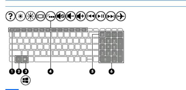
Keys
 NOTE: Your computer may look slightly di erent from the illustration below.
Item |
Component |
Description |
|
|
|
(1) |
esc key |
Displays system information when pressed in combination |
|
|
with the fn key. |
|
|
|
(2) |
fn key |
Displays system information when pressed in combination |
|
|
with the esc key. |
|
|
|
(3) |
Windows key |
Opens the Start menu. |
|
|
NOTE: Pressing the Windows key again will close |
|
|
the Start menu. |
|
|
|
(4) |
Action keys |
Execute frequently used system functions. |
|
|
NOTE: On select products, the f5 action key turns |
|
|
the keyboard backlight feature o or on. |
|
|
|
(5) |
num lock key (select products only) |
Alternates between the navigational and numeric functions |
|
|
on the integrated numeric keypad. |
|
|
|
(6) |
Integrated numeric keypad (select products only) |
When num lock is on, the keypad can be used like an external |
|
|
numeric keypad. |
|
|
|
6 Chapter 2 External component identi cation
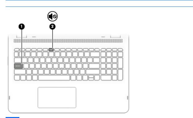
Lights
 NOTE: Your computer may look slightly di erent from the illustration below.
Item |
Component |
Description |
|
|
|
|
|
(1) |
Caps lock light |
On: Caps lock is on, which switches the key input to all |
|
|
|
capital letters. |
|
|
|
|
|
(2) |
Mute light |
● |
Amber: Computer sound is o . |
|
|
● |
: Computer sound is on. |
|
|
|
|
Lights 7
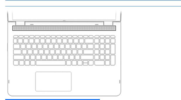
Speakers
 NOTE: Your computer may look slightly di erent from the illustration below.
Component |
Description |
|
|
Speakers |
Produce sound. |
|
|
8 Chapter 2 External component identi cation

TouchPad
Item |
Component |
Description |
|
|
|
(1) |
TouchPad zone |
Reads your nger gestures to move the pointer or activate |
|
|
items on the screen. |
|
|
|
(2) |
Left TouchPad button |
Functions like the left button on an external mouse. |
|
|
|
(3) |
Right TouchPad button |
Functions like the right button on an external mouse. |
|
|
|
TouchPad 9
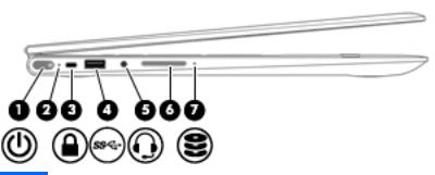
Left side
Item |
Component |
Description |
|
|
|
|
|
(1) |
Power button |
● |
When the computer is o , press the button to turn on |
|
|
|
the computer. |
|
|
● |
When the computer is on, press the button brie y to |
|
|
|
initiate Sleep. |
|
|
● |
When the computer is in the Sleep state, press |
|
|
|
the button brie y to exit Sleep. |
|
|
● |
When the computer is in Hibernation, press the button |
|
|
|
brie y to exit Hibernation. |
|
|
CAUTION: Pressing and holding down the power button |
|
|
|
results in the loss of unsaved information. |
|
|
|
If the computer has stopped responding and shutdown |
|
|
|
procedures are ine ective, press and hold the power button |
|
|
|
down for at least 5 seconds to turn o the computer. |
|
|
|
To learn more about your power settings, see your |
|
|
|
power options. |
|
|
|
▲ |
Type power in the taskbar search box, and then select |
|
|
|
Power and sleep settings. |
|
|
|
‒ or – |
|
|
|
Right-click the Start button, and then select |
|
|
|
Power Options. |
|
|
|
|
(2) |
Power light |
● |
On: The computer is on. |
|
|
● |
Blinking: The computer is in the Sleep state, a power- |
|
|
|
saving state. The computer shuts o power to |
|
|
|
the display and other unneeded components. |
|
|
● |
: The computer is o or in Hibernation. Hibernation |
|
|
|
is a power-saving state that uses the least amount |
|
|
|
of power. |
|
|
|
|
(3) |
Security cable slot |
Attaches an optional security cable to the computer. |
|
|
|
NOTE: The security cable is designed to act as a deterrent, |
|
|
|
but it may not prevent the computer from being mishandled |
|
|
|
or stolen. |
|
|
|
|
|
(4) |
USB 2.0 port |
Connects an optional USB device, such as a keyboard, mouse, |
|
|
|
external drive, printer, scanner, or USB hub. |
|
|
|
|
|
(5) |
Audio-out (headphone)/Audio-in (microphone) combo jack |
Connects optional powered stereo speakers, headphones, |
|
|
|
earbuds, a headset, or a television audio cable. Also connects |
|
|
|
|
|
10 Chapter 2 External component identi cation

Item |
Component |
Description |
|
|
|
|
|
(5) |
Audio-out (headphone)/Audio-in (microphone) combo jack |
an optional headset microphone. This jack does not support |
|
|
(continued) |
optional standalone microphones. |
|
|
|
WARNING! To reduce the risk of personal injury, adjust |
|
|
|
the volume before putting on headphones, earbuds, or a |
|
|
|
headset. For additional safety information, refer to |
|
|
|
the Regulatory, Safety, and Environmental Notices. |
|
|
|
To access this guide: |
|
|
|
▲ |
Select the Start button, select All apps, select HP Help |
|
|
|
and Support, and then select HP Documentation. |
|
|
NOTE: When a device is connected to the jack, |
|
|
|
the computer speakers are disabled. |
|
|
|
|
|
(6) |
Volume button |
Control speaker volume on the computer. |
|
|
|
1. |
To increase speaker volume, press the back edge of |
|
|
|
the button. |
|
|
2. |
To decrease speaker volume, press the front edge of |
|
|
|
the button. |
|
|
|
|
(7) |
Drive light |
● |
Blinking white: The hard drive is being accessed. |
|
|
● |
Amber: HP 3D DriveGuard has temporarily parked |
|
|
|
the hard drive. |
NOTE: On select products, the drive light will always remain o .
Left side 11

Right side
Item |
Component |
Description |
|
|
|
|
|
(1) |
Memory card reader |
Reads optional memory cards that enable you to store, |
|
|
|
manage, share, or access information. |
|
|
|
To insert a card: |
|
|
|
1. |
Hold the card label-side up, with connectors facing |
|
|
|
the computer. |
|
|
2. |
Insert the card into the memory card reader, and then |
|
|
|
press in on the card until it is rmly seated. |
|
|
To remove a card: |
|
|
|
▲ |
Press in on the card, and then remove it from |
|
|
|
the memory card reader. |
|
|
|
|
(2) |
USB Type-C port |
Connects an optional USB device with a Type-C connector. |
|
|
|
|
|
(3) |
USB 3.0 charging (powered) port |
Connects an optional USB device, such as a keyboard, mouse, |
|
|
|
external drive, printer, scanner, or USB hub. Standard USB |
|
|
|
ports will not charge all USB devices or will charge using a |
|
|
|
low current. Some USB devices require power and require |
|
|
|
you to use a powered port. |
|
|
|
NOTE: USB charging ports can also charge select models of |
|
|
|
cell phones and MP3 players, even when the computer is o . |
|
|
|
|
|
(4) |
HDMI port |
Connects an optional video or audio device, such as a high- |
|
|
|
de |
nition television, any compatible digital or audio |
|
|
component, or a high-speed igh- e nition Multimedia |
|
|
|
Interface (HDMI) device. |
|
|
|
|
|
(5) |
AC adapter and battery light |
● |
White: The AC adapter is connected and the battery is |
|
|
|
fully charged. |
|
|
● |
Blinking white: The AC adapter is disconnected and |
|
|
|
the battery has reached a low battery level. |
|
|
● |
Amber: The AC adapter is connected and the battery |
|
|
|
is charging. |
|
|
● |
: The battery is not charging. |
|
|
|
|
(6) |
Power connector |
Connects an AC adapter. |
|
|
|
|
|
12 Chapter 2 External component identi cation
Bottom
Component |
Description |
|
|
Vents (2) |
Enable air ow to cool internal components. |
|
NOTE: The computer fan starts up automatically to cool |
|
internal components and prevent overheating. It is normal |
|
for the internal fan to cycle on and o during routine |
|
operation. |
|
|
Bottom 13

3Illustrated parts catalog
Service tag
When ordering parts or requesting information, provide the computer serial number and model number provided on the service tag.
Item |
Description |
Function |
|
|
|
(1) |
Model description |
This is the alphanumeric identi er used to locate |
|
|
documents, drivers, and support for the computer. |
|
|
|
(2) |
Serial number (s/n) |
This is an alphanumeric identi er that is unique to |
|
|
each product. |
|
|
|
(3) |
Part number/Product number (p/n) |
This number provides speci c information about |
|
|
the product's hardware components. The part number helps |
|
|
a service technician to determine what components |
|
|
and parts are needed. |
|
|
|
(4) |
Warranty period |
This number describes the duration of the warranty period |
|
|
for the computer. |
|
|
|
14 Chapter 3 Illustrated parts catalog

Computer major components
Item |
Component |
Spare part number |
(1)Display assembly: The display assembly is spared at the subcomponent level only. For more display assembly spare part information, see Display components on page 17.
(2) |
Keyboard/top cover (in dark ash silver nish; includes TouchPad and cable, backlight cable, and keyboard cable): |
|
|
|
|
|
For use in Denmark, Finland, and Norway |
857285-DH1 |
|
|
|
|
For use in the United Kingdom |
857285-031 |
|
|
|
|
For use in the United States |
857285-001 |
|
|
|
Computer major components 15
Loading...