


 Loading...
Maintenance and Service Guide
HP ENVY x360 15 Convertible PC IMPORTANT! This document is intended for HP authorized service providers only.
© Copyright 2020 HP Development Company,
L.P.
Bluetooth is a trademark owned by its proprietor and used by HP Inc. under license. Intel and Core are trademarks of Intel Corporation or its subsidiaries in the U.S. and other countries. Intel, the Intel logo and Iris are trademarks of Intel Corporation or its subsidiaries in the U.S. and/or other countries. Microsoft and Windows are either registered trademarks or trademarks of Microsoft Corporation in the United States and/or other countries. NVIDIA, the NVIDIA logo, and are trademarks and/or registered trademarks of NVIDIA Corporation in the U.S. and other countries. SD Logo is a trademark of its proprietor.
The information contained herein is subject to change without notice. The only warranties for HP products and services are set forth in the express warranty statements accompanying such products and services. Nothing herein should be construed as constituting an additional warranty. HP shall not be liable for technical or editorial errors or omissions contained herein.
First Edition: March 2020
Document Part Number: L84426-001
Product notice
This guide describes features that are common to most models. Some features may not be available on your computer.
Not all features are available in all editions or versions of Windows. Systems may require upgraded and/or separately purchased hardware, drivers, software or BIOS update to take full advantage of Windows functionality. Windows 10 is automatically updated, which is always enabled. ISP fees may apply and additional requirements may apply over time for updates. Go to http://www.microsoft.com for details.
To access the latest user guides, go to http://www.hp.com/support, and follow the instructions to nd your product. Then select Manuals.
Software terms
By installing, copying, downloading, or otherwise using any software product preinstalled on this computer, you agree to be bound by the terms of the HP End User License Agreement (EULA). If you do not accept these license terms, your sole remedy is to return the entire unused product (hardware and software) within 14 days for a full refund subject to the refund policy of your seller.
For any further information or to request a full refund of the price of the computer, please contact your seller.
iii
iv

Safety warning notice
 WARNING! To reduce the possibility of heat-related injuries or of overheating the device, do not place the device directly on your lap or obstruct the device air vents. Use the device only on a hard, flat surface. Do not allow another hard surface, such as an adjoining optional printer, or a soft surface, such as pillows or rugs or clothing, to block airflow. Also, do not allow the AC adapter to contact the skin or a soft surface, such as pillows or rugs or clothing, during operation. The device and the AC adapter comply with the user-accessible surface temperature limits de ned by applicable safety standards.
v
vi Safety warning notice

Table of contents
1 Product description .................................................................................................................................................................................. |
1 |
2 Components .............................................................................................................................................................................................. |
4 |
Locating hardware .................................................................................................................................................................... |
4 |
Locating software ..................................................................................................................................................................... |
4 |
Right side ................................................................................................................................................................................... |
5 |
Left side ..................................................................................................................................................................................... |
6 |
Display ........................................................................................................................................................................................ |
7 |
Low blue light mode (select products only) .................................................................................................... |
7 |
Keyboard area ........................................................................................................................................................................... |
8 |
Touchpad ............................................................................................................................................................... |
8 |
Touchpad settings ........................................................................................................................... |
8 |
Lights ..................................................................................................................................................................... |
9 |
Button, speakers, and ngerprint reader ...................................................................................................... |
10 |
Special keys ........................................................................................................................................................ |
12 |
Bottom ..................................................................................................................................................................................... |
13 |
Labels ....................................................................................................................................................................................... |
14 |
3 Illustrated parts catalog ........................................................................................................................................................................ |
16 |
Computer major components .............................................................................................................................................. |
16 |
Display components .............................................................................................................................................................. |
21 |
Miscellaneous parts ............................................................................................................................................................... |
23 |
4 Removal and replacement procedures preliminary requirements ................................................................................................ |
25 |
Tools required ......................................................................................................................................................................... |
25 |
Service considerations .......................................................................................................................................................... |
25 |
Plastic parts ........................................................................................................................................................ |
25 |
Cables and connectors ..................................................................................................................................... |
25 |
Drive handling .................................................................................................................................................... |
26 |
Electrostatic discharge damage .......................................................................................................................................... |
26 |
Packaging and transporting guidelines .............................................................................................................................. |
27 |
Workstation guidelines .......................................................................................................................................................... |
28 |
Equipment guidelines ............................................................................................................................................................ |
28 |
5 Removal and replacement procedures .............................................................................................................................................. |
30 |
Component replacement procedures ................................................................................................................................. |
30 |
vii
Bottom cover ...................................................................................................................................................... |
30 |
Front speakers ................................................................................................................................................... |
32 |
Solid-state drive ................................................................................................................................................ |
33 |
Memory module ................................................................................................................................................ |
35 |
WLAN module .................................................................................................................................................... |
37 |
Fan ....................................................................................................................................................................... |
39 |
Heat sink ............................................................................................................................................................. |
41 |
Infrared board cable .......................................................................................................................................... |
43 |
Infrared board .................................................................................................................................................... |
44 |
Display assembly ............................................................................................................................................... |
45 |
Power connector cable ..................................................................................................................................... |
52 |
Rear speaker ...................................................................................................................................................... |
54 |
Battery ................................................................................................................................................................. |
55 |
Touchpad cable .................................................................................................................................................. |
56 |
Touchpad ............................................................................................................................................................ |
57 |
System board ..................................................................................................................................................... |
59 |
USB port cover ................................................................................................................................................... |
62 |
6 Computer Setup (BIOS), TPM, and HP Sure Start .............................................................................................................................. |
64 |
Using Computer Setup .......................................................................................................................................................... |
64 |
Starting Computer Setup ................................................................................................................................. |
64 |
Navigating and selecting in Computer Setup ................................................................................................ |
64 |
Restoring factory settings in Computer Setup ............................................................................................. |
64 |
Updating the BIOS ............................................................................................................................................. |
65 |
Determining the BIOS version ..................................................................................................... |
65 |
Downloading a BIOS update ........................................................................................................ |
65 |
Changing the boot order using the f9 prompt .............................................................................................. |
66 |
TPM BIOS settings (select products only) .......................................................................................................................... |
66 |
Using HP Sure Start (select products only) ........................................................................................................................ |
67 |
7 Backing up, restoring, and recovering ................................................................................................................................................. |
68 |
Backing up information and creating recovery media ..................................................................................................... |
68 |
Using Windows tools ......................................................................................................................................... |
68 |
Using the HP Cloud Recovery Download Tool to create recovery media (select products only) .......... |
68 |
Restoring and recovery ......................................................................................................................................................... |
69 |
Restoring, resetting, and refreshing using Windows tools ......................................................................... |
69 |
Recovering using HP Recovery media ............................................................................................................ |
69 |
Changing the computer boot order ................................................................................................................ |
69 |
Using HP Sure Recover (select products only) .............................................................................................. |
70 |
viii
8 Using HP PC Hardware Diagnostics ..................................................................................................................................................... |
71 |
Using HP PC Hardware Diagnostics Windows (select products only) ............................................................................ |
71 |
Downloading HP PC Hardware Diagnostics Windows ................................................................................. |
71 |
Downloading the latest HP PC Hardware Diagnostics Windows version ............................. |
72 |
Downloading HP Hardware Diagnostics Windows by product name or number |
|
(select products only) ................................................................................................................... |
72 |
Installing HP PC Hardware Diagnostics Windows ......................................................................................... |
72 |
Using HP PC Hardware Diagnostics UEFI ............................................................................................................................ |
72 |
Starting HP PC Hardware Diagnostics UEFI ................................................................................................... |
73 |
Downloading HP PC Hardware Diagnostics UEFI to a USB flash drive ...................................................... |
73 |
Downloading the latest HP PC Hardware Diagnostics UEFI version ..................................... |
73 |
Downloading HP PC Hardware Diagnostics UEFI by product name or number (select |
|
products only) ............................................................................................................................... |
73 |
Using Remote HP PC Hardware Diagnostics UEFI settings (select products only) ...................................................... |
74 |
Downloading Remote HP PC Hardware Diagnostics UEFI .......................................................................... |
74 |
Downloading the latest Remote HP PC Hardware Diagnostics UEFI version ...................... |
74 |
Downloading Remote HP PC Hardware Diagnostics UEFI by product name or number ... |
74 |
Customizing Remote HP PC Hardware Diagnostics UEFI settings ............................................................ |
74 |
9 peci cations .......................................................................................................................................................................................... |
76 |
Computer speci cations ........................................................................................................................................................ |
76 |
10 Backing up, restoring, and recovering .............................................................................................................................................. |
68 |
Backing up information and creating recovery media ..................................................................................................... |
78 |
Using Windows tools ......................................................................................................................................... |
68 |
Using the HP Cloud Recovery Download Tool to create recovery media (select products only) .......... |
68 |
Restoring and recovery ......................................................................................................................................................... |
69 |
Restoring, resetting, and refreshing using Windows tools ......................................................................... |
79 |
Recovering using HP Recovery media ............................................................................................................ |
79 |
Changing the computer boot order ................................................................................................................ |
69 |
Using HP Sure Recover (select products only) .............................................................................................. |
80 |
11 Power cord set requirements ............................................................................................................................................................ |
81 |
Requirements for all countries ............................................................................................................................................ |
81 |
Requirements for speci c countries and regions ............................................................................................................. |
82 |
12 Recycling ............................................................................................................................................................................................... |
84 |
Index ............................................................................................................................................................................................................. |
85 |
ix
x
1Product description
Table 1-1 Product description
Category |
Description |
|
|
|
|
Product Name |
HP ENVY x360 15 Convertible PC |
|
|
|
|
Processor |
● |
Intel® Core™ i7-1065G7 1.3 GHz (SC turbo up to 3.9 GHz) quad core processor (8.0 MB L3 cache, |
|
|
3200 MHz FSB, 15 W) |
|
● |
Intel Core i7-10510U 1.8 GHz (SC turbo up to 4.9 GHz) quad core processor (8.0 MB L3 cache, |
|
|
2666 MHz FSB, 15 W) |
|
● |
Intel Core i5-1035G1 1.0 GHz (SC turbo up to 3.6 GHz) quad core processor (6.0 MB L3 cache, |
|
|
3200 MHz FSB, 15 W) |
|
● |
Intel Core i5-10210U 1.6 GHz (SC turbo up to 4.2 GHz) quad core processor (6.0 MB L3 cache, |
|
|
2666 MHz FSB, 15 W) |
|
|
|
Chipset |
Intel integrated with soldered-on-circuit (SoC) processor |
|
|
|
|
Graphics |
Intel Iris® Plus integrated (only on computer models equipped with an Intel Core i7-1065G7 processor) |
|
|
Intel UHD Graphics integrated |
|
|
Nvidia® GeForce MX330 with 4 GB graphic controller |
|
|
|
|
Panel |
● |
15.6 inch, touchscreen, ultra high-de nition (UHD) (3840×2160), brightview, organic light- |
|
|
emitting diode (OLED), UWVA, AMOLED, DCI-P3 100, eDP+PSR, display panel with narrow bezel; |
|
|
typical brightness: 400 nits |
|
● |
15.6 inch, touchscreen, full high-de nition (FHD) (1920×1080), antiglare, white light-emitting |
|
|
(WLED), UWVA, eDP1.4+PSR, low power display panel with narrow bezel; typical brightness: |
|
|
400 nits |
|
● |
15.6 inch, touchscreen, FHD (1920×1080), antiglare, WLED, UWVA, eDP1.2, display panel with |
|
|
narrow bezel; typical brightness: 250 nits |
|
|
|
Memory |
Support for the following: |
|
|
DDR4-3200, 1.2 V, nonupgradeable, onboard system memory in 16 GB, 12 GB, and |
|
|
8 GB con gurations |
|
|
DDR4-2666, 1.2 V, nonupgradeable, onboard system memory in 16 GB, 12 GB, and |
|
|
8 GB con gurations |
|
|
|
|
Storage |
Support for the following solid-state drives: |
|
|
● |
1 TB, M.2 2280, peripheral component interconnect express (PCIe), non-volatile memory |
|
|
express (NVMe) 3×4, SuperSpeed (SS) solid-state drive with triple layer cell (TLC) |
|
● |
1 TB, M.2 2280, PCIe, NVMe value solid-state drive |
|
● |
512 GB, M.2 2280, PCIe 3×4, solid-state drive with TLC |
|
● |
512 GB, M.2 2280, PCIe, NVMe value solid-state drive |
|
● |
512 GB 2280 PCIe-3×2×2 NVMe + 32 GB 3D Xpoint solid-state drive |
|
● |
256 GB, M.2 2280, PCIe 3×4, solid-state drive with TLC |
|
● |
256 GB, M.2 2280, PCIe, NVMe value solid-state drive |
|
● |
256 GB 2280 PCIe-3×2×2 NVMe + 16 GB 3D Xpoint solid-state drive |
|
|
|
1

Table 1-1 Product description (continued)
Category |
Description |
|
|
|
|
Audio and video |
Fixed (no tilt), 720p HD camera integrated into display assembly |
|
|
Dual array digital microphones with appropriate beam-forming, echo-cancellation, noise-suppression |
|
|
software |
|
|
BANG and OLUFSEN speakers |
|
|
HP support for Far Field Cortana |
|
|
Support for speaker swap |
|
|
Three speakers |
|
|
|
|
Wireless |
Integrated wireless local area network (WLAN) with two built-in antenna(s)(s) |
|
|
Support for the following WLAN modules: |
|
|
● |
Intel Wi-Fi 6 AX201 ax 2×2 + Bluetooth® 5.0 MU-MIMO M.2 2230 non-vPro MIPI+BRI WW with |
|
|
2 antenna(s)(s) |
|
● |
Intel 9560 ac 2×2 MU-MIMO + Bluetooth 5.0 M.2 non-vPro MIPI+BRI WW with 2 antenna(s)(s) |
|
|
|
Ports |
● |
AC Smart Pin adapter plug |
|
● |
igh-de nition multimedia interface (HDMI) v2.0 + high-bandwidth digital content protection |
|
|
(HDCP) v2.2 |
|
● |
Headphone/microphone combo jack |
|
● |
USB 3.2 Gen 2 type-C port |
|
● |
USB 3.2 Gen 1 type-A ports (2) |
|
|
|
Expansion |
One next generation form factor (NGFF) slot for a solid-state drive |
|
|
One NGFF slot for a WLAN module |
|
|
|
|
Multimedia card |
HP Multi-Format Digital Media Card Reader |
|
|
|
|
Keyboard/pointing devices |
Island-style keyboard with 3-coat paint, backlit, with numeric keypad in natural silver and sky black |
|
|
nishes |
|
|
Touchpad with image sensor with the following requirements: |
|
|
● |
Clickpad with image sensor |
|
● |
Multitouch gestures enabled |
|
● |
Precision touchpad supported |
|
● |
Support modern trackpad gestures |
|
● |
Taps enabled as default |
|
|
|
Power requirements |
Support for a 3 cell, 51 WHr, 4.45 AHr, Li-ion battery |
|
|
Support for the following AC adapters: |
|
|
● |
65 W HP Smart AC adapter (non-PFC, EM, RC, 4.5 mm) |
|
● |
65 W HP Smart AC adapter (slim, 4.5 mm, 1.8 m) |
|
● |
65 W HP Smart AC adapter (slim, 4.5 mm, 1.8 m) |
|
● |
AC adapter, C5, for use only in Japan |
|
Support for a 1.0 meter, C5 premium power cord with sticker |
|
|
|
|
Security |
Fingerprint reader (Secure Payment) |
|
2Chapter 1 Product description

Table 1-1 Product description (continued)
Category |
Description |
|
|
|
|
|
Trusted Platform Module (TPM) 2.0 rmware |
|
|
|
|
Sensors |
● |
Accelerometer |
|
● |
Accelerometer + gyroscope + eCompass |
|
● |
Infrared thermal sensor |
|
● |
Sensor hub |
|
|
|
Operating system |
Preinstalled: |
|
|
● |
Windows® 10 Home 64-bit |
|
● |
Windows 10 Home 64-bit Advanced |
|
● |
Windows 10 Home 64-bit Advanced Single Language |
|
● |
Windows 10 Home 64-bit High-End Chinese Market CPPP |
|
● |
Windows 10 Home 64-bit Plus |
|
● |
Windows 10 Home 64-bit Plus Single Language |
|
● |
Windows 10 Home 64-bit Plus Single Language Africa Market PPP |
|
● |
Windows 10 Home S 64-bit Plus Single Language Africa PPP |
|
● |
Windows 10 Professional 64-bit |
|
|
|
Serviceability |
End user replaceable parts: AC adapter |
|
|
|
|
3

2Components
The computer features top-rated components. This chapter provides details about the components, where they are located, and how they work.
Locating hardware
To nd out what hardware is installed on the computer:
▲Type device manager in the taskbar search box, and then select the Device Manager app.
A list displays all the devices installed on the computer.
For information about system hardware components and the system BIOS version number, press fn+esc (select products only).
Locating software
Software can vary by product. To nd out what software is installed on the computer:
▲Right-click the Start button, and then select Apps and Features.
4Chapter 2 Components
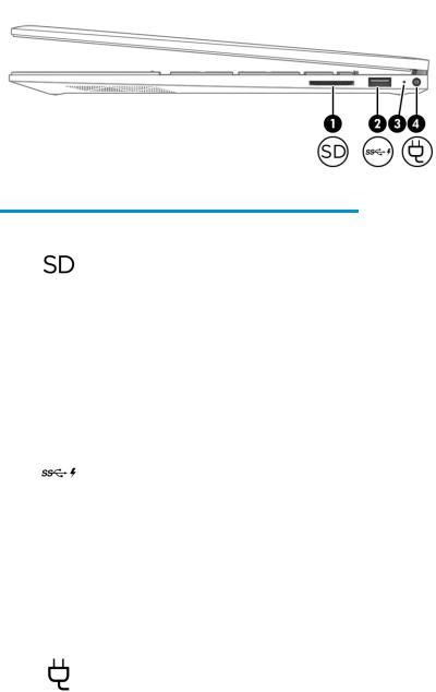
Right side
Table 2-1 Right-side components and their descriptions
Component |
|
Description |
|
|
|
|
|
(1) |
Memory card reader |
Reads optional memory cards that enable you to store, |
|
|
|
manage, share, or access information. |
|
|
|
To insert a card: |
|
|
|
1. |
Hold the card label-side up, with connectors facing |
|
|
|
the computer. |
|
|
2. |
Insert the card into the memory card reader, and then |
|
|
|
press in on the card until it is rmly seated. |
|
|
To remove a card: |
|
|
|
▲ |
Press in on the card, and then remove it from the |
|
|
|
memory card reader. |
|
|
|
|
(2) |
USB SuperSpeed port with HP Sleep and Charge |
Connects a USB device, provides high-speed data transfer, |
|
|
|
and even when the computer is o , charges most products |
|
|
|
such as a cell phone, camera, activity tracker, or smartwatch. |
|
|
|
|
|
(3) |
AC adapter and battery light |
● |
White: The AC adapter is connected and the battery is |
|
|
|
fully charged. |
|
|
● |
Blinking white: The AC adapter is disconnected and the |
|
|
|
battery has reached a low battery level. |
|
|
● |
Amber: The AC adapter is connected and the battery |
|
|
|
is charging. |
|
|
● |
O : The battery is not charging. |
|
|
|
|
(4) |
Power connector |
Connects an AC adapter. |
|
|
|
|
|
Right side |
5 |
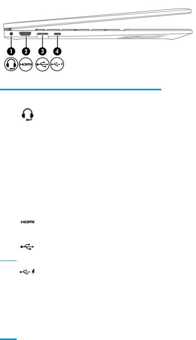
Left side
Table 2-2 Left-side components and their descriptions
Component |
|
Description |
|
|
|
|
|
(1) |
Audio-out (headphone)/Audio-in (microphone) combo |
Connects optional powered stereo speakers, headphones, |
|
|
jack |
earbuds, a headset, or a television audio cable. Also connects |
|
|
|
an optional headset microphone. This jack does not support |
|
|
|
optional standalone microphones. |
|
|
|
WARNING! To reduce the risk of personal injury, adjust the |
|
|
|
volume before putting on headphones, earbuds, or a |
|
|
|
headset. For additional safety information, see the |
|
|
|
Regulatory, Safety, and Environmental Notices. |
|
|
|
To access this guide: |
|
|
|
▲ |
Type HP Documentation in the taskbar search |
|
|
|
box, and then select HP Documentation. |
|
|
NOTE: When a device is connected to the jack, the |
|
|
|
computer speakers are disabled. |
|
|
|
|
|
(2) |
HDMI port |
Connects an optional video or audio device, such as a high- |
|
|
|
de |
nition television, any compatible digital or audio |
|
|
component, or an HDMI device. |
|
|
|
|
|
(3) |
USB SuperSpeed port with HP Sleep and Charge |
Connects a USB device, provides high-speed data transfer, |
|
|
|
and even when the computer is o , charges most products |
|
|
|
such as a cell phone, camera, activity tracker, or smartwatch. |
|
(4)USB SuperSpeed Type-C port with HP Sleep and Charge
Connects a USB device that has a Type-C connector, provides data transfer, and even when the computer is o , charges most products such as a cell phone, camera, activity tracker, or smartwatch.
– and –
Connects a display device that has a USB Type-C connector, providing DisplayPort™ output.
NOTE: Cables, adapters, or both (purchased separately) might be required.
6Chapter 2 Components
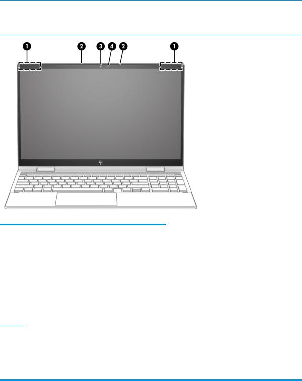
Display
Low blue light mode (select products only)
The computer display is shipped from the factory in low blue light mode for improved eye comfort and safety. Also, blue light mode automatically adjusts blue light emissions when using the computer at night or for reading.
 WARNING! To reduce the risk of serious injury, read the Safety & Comfort Guide. It describes proper workstation setup and proper posture, health, and work habits for computer users. The Safety & Comfort Guide also provides important electrical and mechanical safety information. The Safety & Comfort Guide is available on the web at http://www.hp.com/ergo.
Table 2-3 Display components and their descriptions
Component |
|
Description |
|
|
|
(1) |
WLAN antenna(s)(s)* |
Send and receive wireless signals to communicate with |
|
|
WLANs. |
|
|
|
(2) |
Internal microphones |
Record sound. |
|
|
|
(3) |
Camera |
Allows video chat, video recording, and still image recording. |
|
|
Some cameras also allow a facial recognition logon to |
|
|
Windows, instead of a password logon. |
|
|
NOTE: Camera functions vary depending on the camera |
|
|
hardware and software installed on the product. |
|
|
|
(4) |
Camera light |
On: The camera is in use. |
*The antenna(s) are not visible from the outside of the computer. For optimal transmission, keep the areas immediately around the antenna(s) free from obstructions.
For wireless regulatory notices, see the section of the Regulatory, Safety, and Environmental Notices that applies to your country or region.
To access this guide:
▲ Type HP Documentation in the taskbar search box, and then select HP Documentation.
Display 7
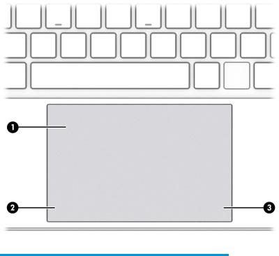
Keyboard area
Keyboards can vary by language.
Touchpad
Touchpad settings
To adjust touchpad settings and gestures, or to turn o the touchpad:
1.Type touchpad settings in the taskbar search box, and then press enter.
2.Choose a setting.
To turn on the touchpad:
1.Type touchpad settings in the taskbar search box, and then press enter.
2.Using an external mouse, click the touchpad button.
– or –
▲Press the Tab key repeatedly until the pointer rests on the touchpad button. Then press the spacebar to select the button.
Table 2-4 Touchpad components and their descriptions
Component |
Description |
|
|
|
|
(1) |
Touchpad zone |
Reads nger gestures to move the pointer or activate items |
|
|
on the screen. |
|
|
|
(2) |
Left touchpad button |
Functions like the left button on an external mouse. |
|
|
|
(3) |
Right touchpad button |
Functions like the right button on an external mouse. |
|
|
|
8Chapter 2 Components

Lights
Table 2-5 Lights and their descriptions
Component |
|
Description |
|
|
|
|
|
(1) |
Caps lock light |
On: Caps lock is on, which switches the key input to all |
|
|
|
capital letters. |
|
|
|
|
|
(2) |
Mute light |
● |
On: Computer sound is o . |
|
|
● |
O : Computer sound is on. |
|
|
|
|
(3) |
Microphone mute light |
● |
On: The microphone is on. |
|
|
● |
O : The microphone is o . |
|
|
|
|
(4) |
Camera privacy light |
● |
On: An integrated camera is o . |
|
|
● |
O : The integrated camera is on. |
|
|
|
|
(5) |
Power light |
● |
On: The computer is on. |
|
|
● |
Blinking: The computer is in the Sleep state, a power- |
|
|
|
saving state. The computer shuts o power to the |
|
|
|
display and other unnecessary components. |
|
|
● |
O : Depending on your computer model, the computer |
|
|
|
is o , in Hibernation, or in Sleep. Hibernation is the |
|
|
|
power-saving state that uses the least amount of |
|
|
|
power. |
|
|
|
|
Keyboard area |
9 |
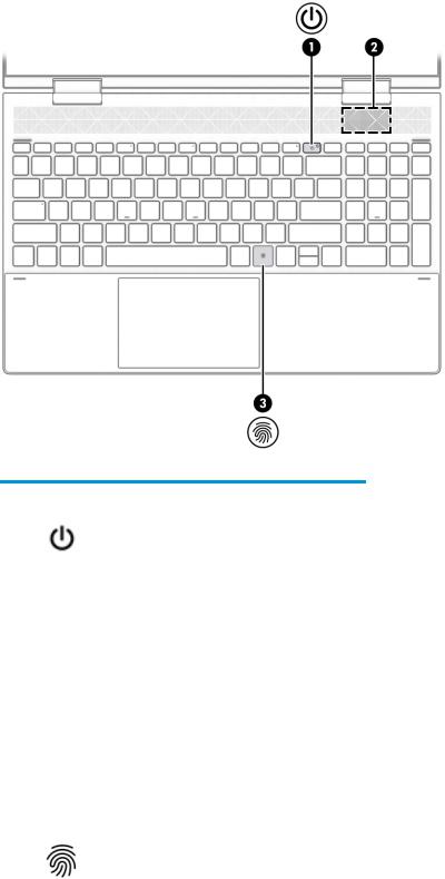
Button, speakers, and ngerprint reader
Table 2-6 Button, speakers, and ngerprint reader and their descriptions
Component |
|
Description |
|
|
|
|
|
(1) |
Power button |
● |
When the computer is o , press the button to turn on |
|
|
|
the computer. |
|
|
● |
When the computer is on, press the button briefly to |
|
|
|
initiate Sleep. |
|
|
● |
When the computer is in the Sleep state, press the |
|
|
|
button briefly to exit Sleep (select products only). |
|
|
● |
When the computer is in Hibernation, press the button |
|
|
|
briefly to exit Hibernation. |
|
|
IMPORTANT: Pressing and holding down the power button |
|
|
|
results in the loss of unsaved information. |
|
|
|
If the computer has stopped responding and shutdown |
|
|
|
procedures are ine ective, press and hold the power button |
|
|
|
down for at least 10 seconds to turn o the computer. |
|
|
|
To learn more about your power settings, see your power |
|
|
|
options. |
|
|
|
|
|
(2) |
Speaker |
Produces sound. |
|
|
|
|
|
(3) |
Fingerprint reader |
Allows a ngerprint logon to Windows, instead of a |
|
|
|
password logon. |
|
|
|
▲ |
Touch your nger to the ngerprint reader. |
10 Chapter 2 Components
Table 2-6 Button, speakers, and |
ngerprint reader and their descriptions (continued) |
|
|
|
|
Component |
Description |
|
|
|
|
|
IMPORTANT: |
To prevent ngerprint logon issues, |
|
make sure when you register your ngerprint that all |
|
|
sides of your |
nger are registered by the ngerprint |
|
reader. |
|
|
|
|
Keyboard area 11
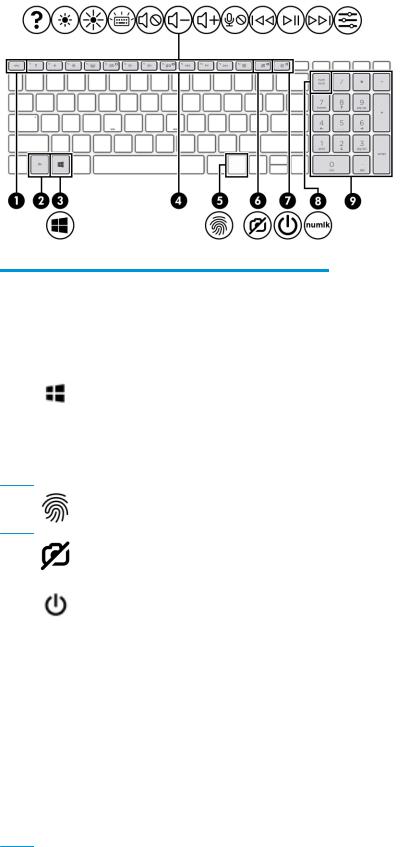
Special keys
Table 2-7 Special keys and their descriptions
Component |
|
Description |
|
|
|
(1) |
esc key |
Displays system information when pressed in combination |
|
|
with the fn key. |
|
|
|
(2) |
fn key |
Executes speci c functions when pressed in combination |
|
|
with another key. |
|
|
|
(3) |
Windows key |
Opens the Start menu. |
|
|
NOTE: Pressing the Windows key again will close the Start |
|
|
menu. |
|
|
|
(4) |
Action keys |
Execute frequently used system functions as de ned by the |
|
|
icon symbols on the f1 through f12 function keys. The action |
|
|
keys vary by computer. |
(5) |
Fingerprint reader (select products only) |
Allows a ngerprint logon to Windows, instead of a password logon.
(6) |
Camera privacy key |
Turns the camera o |
and on. |
|
|
|
|
|
|
(7) |
Power button |
● |
When the computer is o , press the button to turn on |
|
|
|
|
the computer. |
|
|
|
● |
When the computer is on, press the button briefly to |
|
|
|
|
initiate Sleep. |
|
|
|
● |
When the computer is in the Sleep state, press the |
|
|
|
|
button briefly to exit Sleep (select products only). |
|
|
|
● |
When the computer is in Hibernation, press the button |
|
|
|
|
briefly to exit Hibernation. |
|
|
|
IMPORTANT: Pressing and holding down the power button |
||
|
|
results in the loss of unsaved information. |
||
|
|
If the computer has stopped responding and shutdown |
||
|
|
procedures are ine |
ective, press and hold the power button |
|
|
|
down for at least 10 seconds to turn o the computer. |
||
To learn more about your power settings, see your power options:
12 Chapter 2 Components

Table 2-7 Special keys and their descriptions (continued)
Component |
|
Description |
|
|
|
(8) |
num lock key |
Alternates between the navigational and numeric functions |
|
|
on the integrated numeric keypad. |
|
|
|
(9) |
Integrated numeric keypad |
A separate keypad to the right of the alphabet keyboard. |
|
|
When num lock is pressed, the keypad can be used like an |
|
|
external numeric keypad. |
NOTE: If the keypad function is active when the computer is turned o , that function is reinstated when the computer is turned back on.
Bottom
Table 2-8 Bottom components and their descriptions
Component |
Description |
|
|
|
|
(1) |
Vent |
Enables airflow to cool internal components. |
|
|
NOTE: The computer fan starts up automatically to cool |
|
|
internal components and prevent overheating. It is normal |
|
|
for the internal fan to cycle on and o during routine |
|
|
operation. |
|
|
|
(2) |
Speakers |
Produce sound. |
|
|
|
Bottom 13
Labels
The labels affixed to the computer provide information that you might need when you troubleshoot system problems or travel internationally with the computer. Labels can be in paper form or imprinted on the product.
 IMPORTANT: Check the following locations for the labels described in this section: the bottom of the computer, inside the battery bay, under the service door, on the back of the display, or on the bottom of a tablet kickstand.
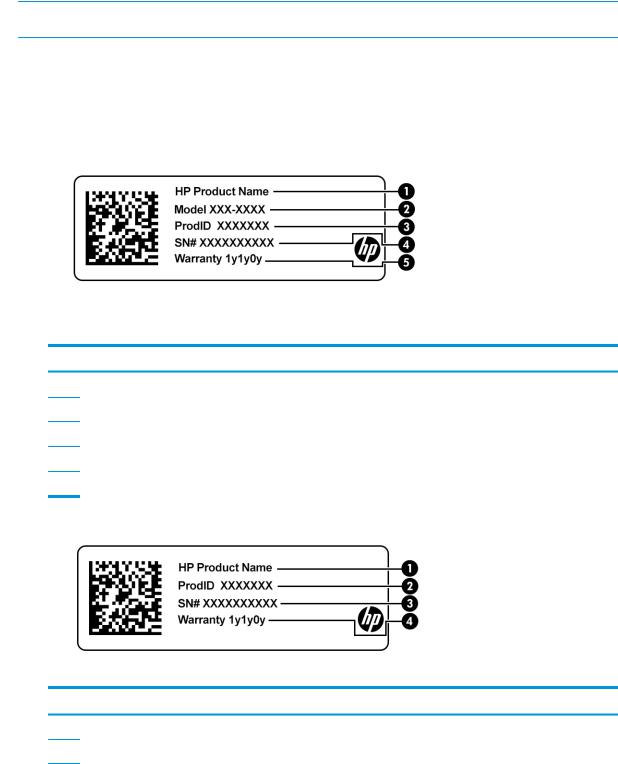
●Service label—Provides important information to identify your computer. When contacting support, you might be asked for the serial number, the product number, or the model number. Locate this information before you contact support.
Your service label will resemble one of the following examples. Refer to the illustration that most closely matches the service label on your computer.
Table 2-9 Service label components
Component
(1)HP product name
(2)Model number
(3)Product ID
(4)Serial number
(5)Warranty period
Table 2-10 Service label components
Component
(1)HP product name
(2)Product ID
14 Chapter 2 Components

Table 2-10 Service label components (continued)
Component
(3)Serial number
(4)Warranty period
●Regulatory label(s)—Provide(s) regulatory information about the computer.
●Wireless certi cation label(s)—Provide(s) information about optional wireless devices and the approval markings for the countries or regions in which the devices have been approved for use.
Labels 15

3Illustrated parts catalog
 NOTE: HP continually improves and changes product parts. For complete and current information about supported parts for your computer, go to http://partsurfer.hp.com, select your country or region, and then follow the on-screen instructions.
Computer major components
16 Chapter 3 Illustrated parts catalog

Table 3-1 Major component spare part information
Item |
Component |
Spare part number |
(1)Display assembly: The display assembly is available as spare parts at the subcomponent level only. For more display assembly spare part information, see Display components on page 21.
(2) |
Keyboard/top cover with backlight and touchpad (keyboard in sky black |
nish, top cover in wood nish, touchpad in sky black |
|
nish; includes backlight cable, keyboard cable, and touchpad cable): |
|
|
|
|
|
NOTE: The touchpad cannot be removed from computer models equipped with a keyboard/top cover with spare part |
|
|
number L93228-xxx). |
|
|
|
|
|
For use in Belgium |
L93228-A41 |
|
|
|
|
For use in Canada |
L93228-DB1 |
|
|
|
|
For use in the Czech Republic and Slovakia |
L93228-FL1 |
|
|
|
|
For use in Denmark, Finland, and Norway |
L93228-DH1 |
|
|
|
|
For use in France |
L93228-051 |
|
|
|
|
For use in Germany |
L93228-041 |
|
|
|
|
For use in Hungary |
L93228-211 |
|
|
|
|
For use in Italy |
L93228-061 |
|
|
|
|
For use in Japan |
L93228-291 |
|
|
|
|
For use in Latin America |
L93228-161 |
|
|
|
|
For use in the Netherlands |
L93228-B31 |
|
|
|
|
For use in Portugal |
L93228-131 |
|
|
|
|
For use in Russia |
L93228-251 |
|
|
|
|
For use in Saudi Arabia |
L93228-171 |
|
|
|
|
For use in South Korea |
L93228-AD1 |
|
|
|
|
For use in Spain |
L93228-071 |
|
|
|
|
For use in Switzerland |
L93228-BG1 |
|
|
|
|
For use in Taiwan |
L93228-AB1 |
|
|
|
|
For use in Turkey |
L93228-141 |
|
|
|
|
For use in the United Kingdom |
L93228-031 |
|
|
|
|
For use in the Uruguay |
L93228-BD1 |
|
|
|
|
For use in the United States |
L93228-001 |
|
|
|
|
Keyboard/top cover with backlight in natural silver nish for use only on computer models with a graphics subsystem with |
|
|
discrete memory (includes backlight cable and keyboard cable): |
|
|
|
|
|
For use in Belgium |
L93227-A41 |
|
|
|
|
For use in Canada |
L93227-DB1 |
|
|
|
|
For use in the Czech Republic and Slovakia |
L93227-FL1 |
|
|
|
|
For use in Denmark, Finland, and Norway |
L93227-DH1 |
|
|
|
|
For use in France |
L93227-051 |
|
|
|
Computer major components 17

Table 3-1 Major component spare part information (continued)
Item |
Component |
Spare part number |
|
|
|
|
For use in Germany |
L93227-041 |
|
|
|
|
For use in Hungary |
L93227-211 |
|
|
|
|
For use in Italy |
L93227-061 |
|
|
|
|
For use in Japan |
L93227-291 |
|
|
|
|
For use in Latin America |
L93227-161 |
|
|
|
|
For use in the Netherlands |
L93227-B31 |
|
|
|
|
For use in Portugal |
L93227-131 |
|
|
|
|
For use in Russia |
L93227-251 |
|
|
|
|
For use in Saudi Arabia |
L93227-171 |
|
|
|
|
For use in South Korea |
L93227-AD1 |
|
|
|
|
For use in Spain |
L93227-071 |
|
|
|
|
For use in Switzerland |
L93227-BG1 |
|
|
|
|
For use in Taiwan |
L93227-AB1 |
|
|
|
|
For use in Turkey |
L93227-141 |
|
|
|
|
For use in the United Kingdom |
L93227-031 |
|
|
|
|
For use in the Uruguay |
L93227-BD1 |
|
|
|
|
For use in the United States |
L93227-001 |
|
|
|
|
Keyboard/top cover with backlight in natural silver |
nish for use only on computer models with a graphics subsystem with |
|
UMA memory (includes backlight cable and keyboard cable): |
|
|
|
|
|
For use in Belgium |
L93226-A41 |
|
|
|
|
For use in Canada |
L93226-DB1 |
|
|
|
|
For use in the Czech Republic and Slovakia |
L93226-FL1 |
|
|
|
|
For use in Denmark, Finland, and Norway |
L93226-DH1 |
|
|
|
|
For use in France |
L93226-051 |
|
|
|
|
For use in Germany |
L93226-041 |
|
|
|
|
For use in Hungary |
L93226-211 |
|
|
|
|
For use in Italy |
L93226-061 |
|
|
|
|
For use in Japan |
L93226-291 |
|
|
|
|
For use in Latin America |
L93226-161 |
|
|
|
|
For use in the Netherlands |
L93226-B31 |
|
|
|
|
For use in Portugal |
L93226-131 |
|
|
|
|
For use in Russia |
L93226-251 |
|
|
|
|
For use in Saudi Arabia |
L93226-171 |
|
|
|
|
For use in South Korea |
L93226-AD1 |
|
|
|
18 Chapter 3 Illustrated parts catalog

Table 3-1 Major component spare part information (continued)
Item |
Component |
Spare part number |
|
|
|
|
For use in Spain |
L93226-071 |
|
|
|
|
For use in Switzerland |
L93226-BG1 |
|
|
|
|
For use in Taiwan |
L93226-AB1 |
|
|
|
|
For use in Turkey |
L93226-141 |
|
|
|
|
For use in the United Kingdom |
L93226-031 |
|
|
|
|
For use in the Uruguay |
L93226-BD1 |
|
|
|
|
For use in the United States |
L93226-001 |
|
|
|
(3) |
Touchpad: |
|
|
|
|
|
In natural silver nish |
L93185-001 |
|
|
|
|
In sky black nish |
L93186-001 |
|
|
|
|
Touchpad cable (not illustrated) |
L93187-001 |
|
|
|
(4) |
Touchpad bracket (not available as a spare part) |
|
|
|
|
(5) |
Front speakers (include left and right front speakers, cables, and 4 rubber isolators |
L93196-001 |
|
|
|
(6) |
Rear speaker (includes rear speaker, cable, and 1 rubber isolator |
L94317-001 |
|
|
|
(7) |
Infrared board |
L93188-001 |
|
|
|
|
Infrared board cable (not illustrated) |
L93189-001 |
|
|
|
(8) |
System board (includes processor, replacement fan gasket, and replacement thermal material): |
|
|
|
|
|
Equipped with an Intel Core i7-1065G7 processor, a graphics subsystem with UMA memory, and |
L93872-601 |
|
the Windows 10 operating system for use only on computer models equipped with an OLED |
|
|
display assembly |
|
|
|
|
|
Replacement thermal pad for use with system board with spare part number L93872-601 |
L93867-001 |
|
(not llustrated) |
|
|
|
|
|
Equipped with an Intel Core i7-1065G7 processor, a graphics subsystem with UMA memory, and |
L93870-601 |
|
the Windows 10 operating system for use only on computer models not equipped with an OLED |
|
|
display assembly |
|
|
|
|
|
Equipped with an Intel Core i7-10510U processor, an Nvidia GeForce MX330 graphics subsystem |
L93874-601 |
|
with 4 GB of discrete memory, and the Windows 10 operating system |
|
|
|
|
|
Equipped with an Intel Core i5-1035G1 processor, a graphics subsystem with UMA memory, and |
L93868-601 |
|
the Windows 10 operating system |
|
|
|
|
|
Equipped with an Intel Core i5-10210U processor, an Nvidia GeForce MX330 graphics subsystem |
L93873-601 |
|
with 4 GB of discrete memory, and the Windows 10 operating system |
|
|
|
|
(9) |
Power connector cable |
L93195-001 |
|
|
|
(10) |
Heat sink (includes replacement thermal material): |
|
|
|
|
|
For use only on computer models equipped with a graphics subsystem with discrete memory |
L93191-001 |
|
|
|
|
For use only on computer models equipped with a graphics subsystem with UMA memory |
L93190-001 |
|
|
|
(11) |
Fan (includes cable): |
|
|
|
|
|
Services the processor |
L93193-001 |
|
|
|
Computer major components 19

Table 3-1 Major component spare part information (continued)
Item |
Component |
Spare part number |
|
|
|
|
Services the graphics subsystem (for use only on computer models equipped with a graphics |
L93194-001 |
|
subsystem with discrete memory) |
|
(12)WLAN module:
|
Intel Wi-Fi 6 AX201 ax 2×2 + Bluetooth 5.0 MU-MIMO M.2 2230 non-vPro MIPI+BRI WW with |
L57250-005 |
|
2 antenna(s) |
|
|
|
|
|
Intel 9560 ac 2×2 MU-MIMO + Bluetooth 5.0 M.2 non-vPro MIPI+BRI WW with 2 antenna(s) |
L22634-005 |
|
|
|
(13) |
Solid-state drive: |
|
|
|
|
|
1 TB, M.2 2280, PCIe, NVMe 3×4, SS solid-state drive with TLC |
L85348-005 |
|
|
|
|
1 TB, M.2 2280, PCIe, NVMe value solid-state drive |
L85370-005 |
|
|
|
|
512 GB, M.2 2280, PCIe 3×4, solid-state drive with TLC |
L85360-005 |
|
|
|
|
512 GB, M.2 2280, PCIe, NVMe value solid-state drive |
L85364-005 |
|
|
|
|
512 GB 2280 PCIe-3×2×2 NVMe + 32 GB 3D Xpoint solid-state drive |
L85366-005 |
|
|
|
|
256 GB, M.2 2280, PCIe 3×4, solid-state drive with TLC |
L85350-005 |
|
|
|
|
256 GB, M.2 2280, PCIe, NVMe value solid-state drive |
L85354-005 |
|
|
|
|
256 GB 2280 PCIe-3×2×2 NVMe + 16 GB 3D Xpoint solid-state drive |
L85356-005 |
|
|
|
(14) |
Memory modules (2, DDR4-3200 MHz, 1.2 v): |
|
|
|
|
|
16 GB (DDR4-3200 MHz, 1.2 v) |
L67710-005 |
|
|
|
|
8 GB |
L83673-005 |
|
|
|
|
4 GB |
L46598-005 |
|
|
|
(15) |
Battery (3 cell, 51 WHr, 4.45 AHr, Li-ion; includes cable) |
L77034-005 |
|
|
|
(16) |
Bottom cover: |
|
|
|
|
|
In natural silver nish |
L94069-001 |
|
|
|
|
In sky black nish |
L94070-001 |
|
|
|
(17) |
Rubber feet: |
|
|
|
|
|
In natural silver nish |
L93197-001 |
|
|
|
|
In sky black nish |
L93198-001 |
|
|
|
|
USB port cover (not illustrated): |
|
|
|
|
|
In natural silver nish |
L94318-001 |
|
|
|
|
In sky black nish |
L94319-001 |
|
|
|
20 Chapter 3 Illustrated parts catalog
Loading...