


EliteOne 1000 G1s

Maintenance & Service Guide
HP EliteOne 1000 G1 All-in-One Business PCs

© Copyright 2017 HP Development Company,
L.P.
AMD is a trademark of Advanced Micro Devices,
Inc. Bluetooth is a trademark owned by its
proprietor and used by HP Inc. under license.
Intel, Celeron, and Pentium are trademarks of
Intel Corporation in the U.S. and other
countries. Microsoft and Windows are
trademarks of the Microsoft group of
companies.
Product notice
This user guide describes features that are
common to most models. Some features may
not be available on your computer.
Software terms
By installing, copying, downloading, or
otherwise using any software product
preinstalled on this computer, you agree to be
bound by the terms of the HP End User License
Agreement (EULA). If you do not accept these
license terms, your sole remedy is to return the
entire unused product (hardware and software)
within 14 days for a full refund subject to the
refund policy of your seller.
The information contained herein is subject to
change without notice. The only warranties for
HP products and services are set forth in the
express warranty statements accompanying
such products and services. Nothing herein
should be construed as constituting an
additional warranty. HP shall not be liable for
technical or editorial errors or omissions
contained herein.
First Edition: September 2017
Document Part Number: 925654-001
For any further information or to request a full
refund of the price of the computer, please
contact your seller.

About This Book
This guide provides basic information for upgrading this computer model.
WARNING! Indicates a hazardous situation that, if not avoided, could result in death or serious injury.
CAUTION: Indicates a hazardous situation that, if not avoided, could result in minor or moderate injury.
IMPORTANT: Indicates information considered important but not hazard-related (for example, messages
related to property damage). A notice alerts the user that failure to follow a procedure exactly as described
could result in loss of data or in damage to hardware or software. Also contains essential information to
explain a concept or to complete a task.
NOTE: Contains additional information to emphasize or supplement important points of the main text.
TIP: Provides helpful hints for completing a task.
iii

iv About This Book

Table of contents
1 Product features ........................................................................................................................................... 1
Overview ................................................................................................................................................................ 1
Base unit top components ..................................................................................................................................... 2
Base unit side components .................................................................................................................................... 2
Base unit rear components .................................................................................................................................... 3
Display front components ..................................................................................................................................... 3
Webcam components ............................................................................................................................................ 4
Infrared (IR) webcam (optional) .......................................................................................................... 4
Full High Denition (FHD) webcam (optional) ..................................................................................... 4
Serial and product number locations .................................................................................................................... 5
2 Illustrated parts catalog ................................................................................................................................ 6
3 Routine care, SATA drive guidelines, and disassembly preparation .................................................................. 10
Electrostatic discharge information .................................................................................................................... 10
Generating static ............................................................................................................................... 11
Preventing electrostatic damage to equipment ............................................................................... 11
Personal grounding methods and equipment .................................................................................. 12
Grounding the work area ................................................................................................................... 12
Recommended materials and equipment ........................................................................................ 12
Operating guidelines ........................................................................................................................................... 13
Routine care ......................................................................................................................................................... 13
General cleaning safety precautions ................................................................................................ 13
Cleaning the computer case .............................................................................................................. 14
Cleaning the keyboard ....................................................................................................................... 14
Cleaning the display .......................................................................................................................... 14
Cleaning the mouse ........................................................................................................................... 15
Service considerations ......................................................................................................................................... 15
Tools and software requirements ..................................................................................................... 15
Screws ............................................................................................................................................... 15
Cables and connectors ...................................................................................................................... 15
Hard Drives ........................................................................................................................................ 15
Lithium coin cell battery .................................................................................................................... 16
4 Removal and replacement procedures ........................................................................................................... 17
Preparing to disassemble the computer ............................................................................................................. 17
v

Base unit access covers ....................................................................................................................................... 18
Display head ......................................................................................................................................................... 20
Internal components ........................................................................................................................................... 21
Memory ................................................................................................................................................................ 22
Memory module specications ......................................................................................................... 22
Populating memory modules ............................................................................................................ 22
Installing memory modules .............................................................................................................. 23
RTC battery .......................................................................................................................................................... 24
Hard drive ............................................................................................................................................................. 26
Fans ...................................................................................................................................................................... 28
Solid-state drive (M.2) ......................................................................................................................................... 30
Display head rear panel ....................................................................................................................................... 31
Camera ................................................................................................................................................................. 32
WLAN module ...................................................................................................................................................... 34
Speakers .............................................................................................................................................................. 35
Antennas .............................................................................................................................................................. 36
Heat sink .............................................................................................................................................................. 37
Processor ............................................................................................................................................................. 38
System board ....................................................................................................................................................... 40
System board callouts ......................................................................................................................................... 44
5 Computer Setup (F10) Utility ........................................................................................................................ 45
Computer Setup (F10) Utilities ............................................................................................................................ 45
Using Computer Setup (F10) Utilities ................................................................................................ 45
Computer Setup–Main ....................................................................................................................... 47
Computer Setup—Security ............................................................................................................... 49
Computer Setup—Advanced ............................................................................................................. 53
Recovering the conguration settings ................................................................................................................ 58
6 Using HP PC Hardware Diagnostics (UEFI) ....................................................................................................... 59
Downloading HP PC Hardware Diagnostics (UEFI) to a USB device .................................................................... 59
Using Remote HP PC Hardware Diagnostics (UEFI) settings (select products only) ........................................... 60
Customizing Remote HP PC Hardware Diagnostics (UEFI) settings ................................................. 60
7 Troubleshooting without diagnostics ............................................................................................................ 61
Safety and comfort .............................................................................................................................................. 61
Before you call for technical support .................................................................................................................. 61
Helpful hints ........................................................................................................................................................ 62
Solving general problems .................................................................................................................................... 63
Solving power problems ...................................................................................................................................... 66
vi

Solving hard drive problems ................................................................................................................................ 67
Solving audio problems ....................................................................................................................................... 69
Solving printer problems ..................................................................................................................................... 70
Solving keyboard and mouse problems .............................................................................................................. 71
Solving hardware installation problems ............................................................................................................. 72
Solving network problems .................................................................................................................................. 74
Solving memory problems .................................................................................................................................. 76
Solving USB ash drive problems ........................................................................................................................ 77
Solving Internet access problems ....................................................................................................................... 78
Solving software problems .................................................................................................................................. 79
8 Backing up, restoring, and recovering ........................................................................................................... 81
Creating recovery media and backups ................................................................................................................ 81
Using HP Recovery media (select products only) ............................................................................. 81
Using Windows tools ......................................................................................................................... 82
Using the HP Cloud Recovery Download Tool (select products only) ............................................... 83
Restore and recovery ........................................................................................................................................... 83
Recovering using HP Recovery Manager ........................................................................................... 83
What you need to know before you get started ............................................................. 83
Using the HP Recovery partition (select products only) ................................................. 84
Using HP Recovery media to recover .............................................................................. 85
Changing the computer boot order ................................................................................ 85
Removing the HP Recovery partition (select products only) ......................................... 85
9 POST error messages and diagnostic front panel LEDs and audible codes ......................................................... 86
POST numeric codes and text messages ............................................................................................................. 86
Interpreting system validation diagnostic front panel LEDs and audible codes ................................................ 91
10 Password security and resetting CMOS ........................................................................................................ 93
Resetting the password jumper .......................................................................................................................... 93
Clearing and resetting the BIOS ........................................................................................................................... 95
Appendix A Power cord set requirements ......................................................................................................... 96
General requirements .......................................................................................................................................... 96
Japanese power cord requirements .................................................................................................................... 96
Country-specic requirements ............................................................................................................................ 97
Appendix B Statement of memory volatility ..................................................................................................... 98
Nonvolatile memory usage ............................................................................................................................... 100
Questions and answers ..................................................................................................................................... 102
vii

Using HP Sure Start (select models only) .......................................................................................................... 103
Appendix C Specications ............................................................................................................................. 104
Index ........................................................................................................................................................... 105
viii

1 Product features
Overview
NOTE: For the latest manuals on this product, go to http://www.hp.com/support. Select Find your product,
and then follow the on-screen instructions.
Overview 1

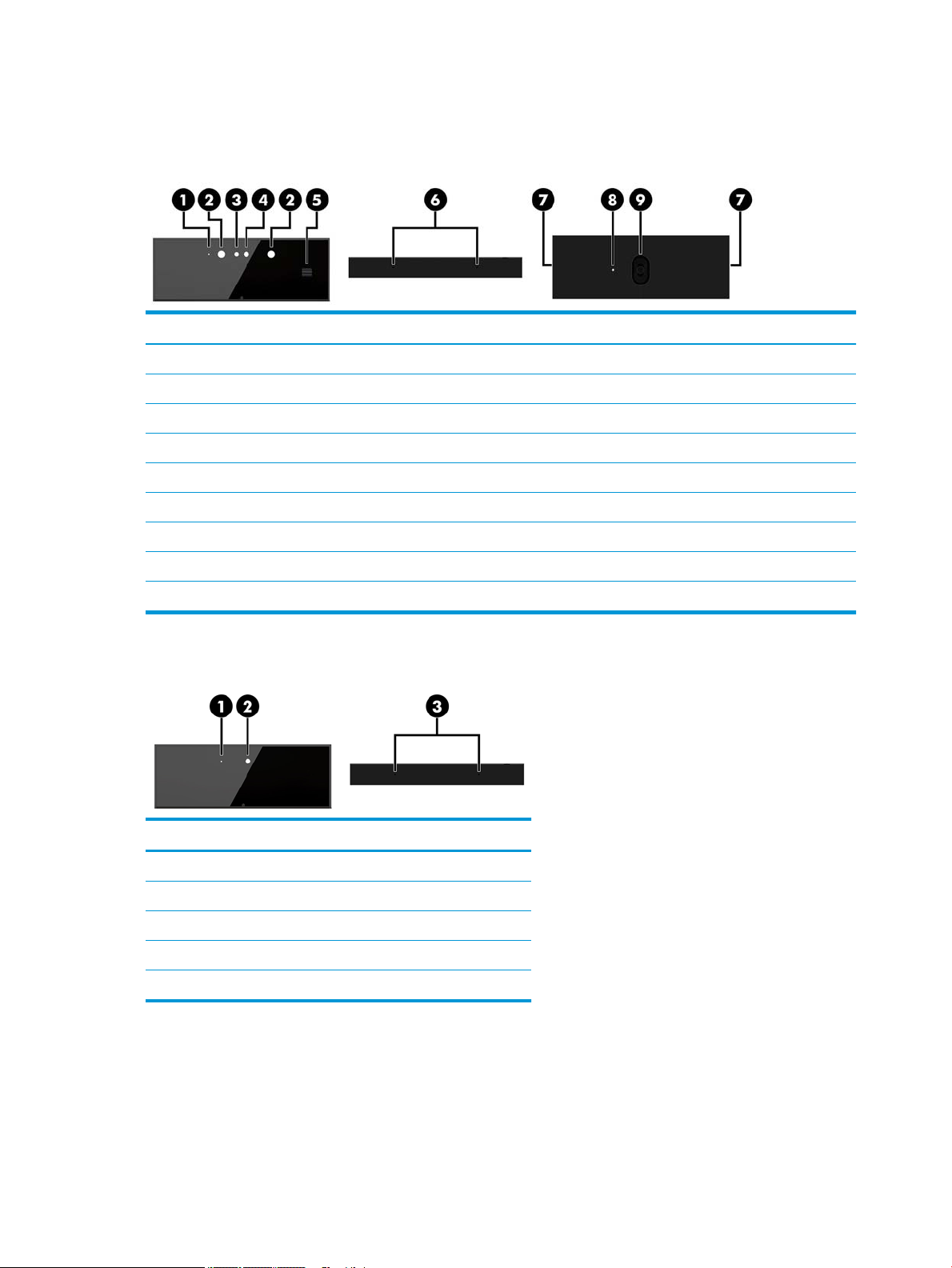
Base unit top components
Components
(1) Power button (5) Hang up button
(2) Call button (6) Speaker mute button
(3) Microphone mute button (7) Volume slider
(4) Webcam mute button
Base unit side components
Components
(1) Scan ngerprint reader (3) USB Type-C charging port
(2) Headset jack (4) USB 3.1 Type-A charging port
2 Chapter 1 Product features

Base unit rear components
Components
(1) Cover removal buttons (5) DisplayPort In
(2) USB 3.1 Type-A ports (4) (6) Power connector
(3) HDMI port (7) RJ-45 (network) jack
(4) DisplayPort Out (8) Security cable slot
Display front components
Components
(1) Webcam
(2) On-screen display buttons (for adjusting the screen)
Base unit rear components 3
Webcam components
Infrared (IR) webcam (optional)
Components
Front View
(1) Webcam light (4) IR webcam
(2) IR light (5) Rear webcam adjustment wheel
(3) Full High Denition (FHD) webcam
Top view
(6) Digital microphones
Rear and side view
(7) Webcam release holes
(8) Webcam light (9) FHD webcam
Full High Denition (FHD) webcam (optional)
Components
Front view
(1) Webcam light
(2) FHD webcam
Top view
(3) Digital microphones
4 Chapter 1 Product features
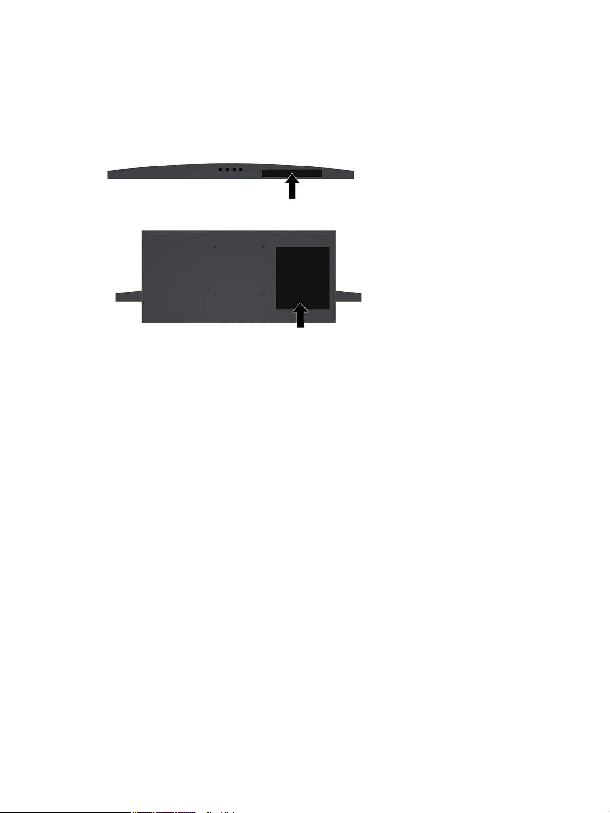
Serial and product number locations
Each computer and display has a unique Commodity Tracking number (CT#) (similar to a serial number) and a
product ID number that are located on the exterior of the device. Keep these numbers available for use when
contacting customer service for assistance.
The display numbers are located on the bottom edge of the display head.
The computer base unit numbers are located on the underside of the base unit.
Serial and product number locations 5
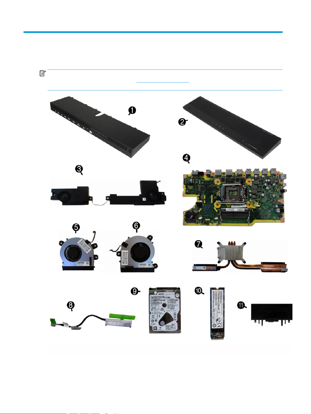
2 Illustrated parts catalog
NOTE: HP continually improves and changes product parts. For complete and current information on
supported parts for your computer, go to http://partsurfer.hp.com, select your country or region, and then
follow the on-screen instructions.
6 Chapter 2 Illustrated parts catalog

Item Description
(1) Rear access cover
(2) Front access cover
(3) Speaker Kit
(4) System board
(5) Right fan
(6) Left fan
(7) Heat sink and pipe
(8) Display cable
(9) Hard drive
2 TB, hybrid SSD, 7 mm
2 TB, 5400 rpm, 7 mm
1 TB, hybrid SSD, 7 mm
1 TB, 7200 rpm, 9.5 mm
500 GB, hybrid SSD, 7 mm
500 GB, 7200 rpm, 7 mm
500 GB, 7200 rpm, self–encrypting (SED), 7 mm
500 GB, 5400 rpm, FIPS, 7 mm
Solid-state drive, 2.5-inch
512 GB, SATA-3, TLC
512 GB, SATA-3, self-encrypting (SED), Opal2. TLC
512 GB, SATA-3, FIPS, TLC
256 GB, SATA-3, TLC
256 GB, SATA-3, self-encrypting (SED), TLC
240 GB, SATA-3, TLC
240 GB, SATA-3, Opal2, TLC
(10) Solid-state drive, M.2
1 TB, SATA-3, TLC
512 GB, FIPS, TLC
512 GB, value, PCIe
256 GB, TLC, PCIe
256 GB, value, PCIe
(11) Camera
1080p (2 MP)
480p, IR
7

Item Description
* Display (whole unit)
23.8-inch, full high-denition (FHD), UWVA, touch screen
23.8-inch, non-touch screen, FHD, UWVA
27-inch, non-touch screen, ultra high-denition (UHD), UWVA
34-inch, non-touch screen, wide quad HD (WQHD), UWVA
* Processor
Intel Core i7-7700 processor
Intel Core i7-6700 processor
Intel Core i5-7600 processor
Intel Core i5-7500 processor
Intel Core i5-6600 processor
Intel Core i5-6500 processor
Intel Core i3-7320 processor
Intel Core i3-7300 processor
Intel Core i3-7100 processor
Intel Core i3-6100 processor
Intel Pentium G4600 processor
Intel Pentium G4620 processor
Intel Pentium G4560 processor
Intel Celeron G3950 processor
Intel Celeron G3930 processor
* Memory modules (PC4-17000)
16 GB
8 GB
4 GB
* WLAN modules
Intel Dual Band Wireless-AC 7265 NV
Intel Dual Band Wireless-AC 8265 (vPro)
Intel Dual Band Wireless-AC 8265 (non-vPro)
Intel Dual Band Wireless-AC 3168
Realtek RTL8821CE 802.11AC 1x1 Wi-Fi + BT 4.2 Combo Adapter
Intel Centrino Wireless-N 2230
* RTC battery
* USB-C to USB-A hub
8 Chapter 2 Illustrated parts catalog

Item Description
* Adapters
USB Type-C to USB 3.0
DisplayPort to DVI
DisplayPort to VGA
DisplayPort to HDMI 1.4
USB to serial
* DisplayPort cable
* Power supply, 180 W (external)
* Mouse
HP PS2 Optical
HP USB Optical
HP USB Laser
USB premium
USB, wired, health care
HP Antimicrobial
HP USB Hardened
HP USB Grey
* Keyboard
Washable, USB/PS2
USB
USB. slim
Wireless keyboard and mouse
USB, slim, smart card
Antimicrobial
Wired, health care
Premium, wireless
9

3 Routine care, SATA drive guidelines, and
disassembly preparation
This chapter provides general service information for the computer. Adherence to the procedures and
precautions described in this chapter is essential for proper service.
CAUTION: When the computer is plugged into an AC power source, voltage is always applied to the system
board. You must disconnect the power cord from the power source before opening the computer to prevent
system board or component damage.
Electrostatic discharge information
A sudden discharge of static electricity from your nger or other conductor can destroy static-sensitive
devices or microcircuitry. Often the spark is neither felt nor heard, but damage occurs. An electronic device
exposed to electrostatic discharge (ESD) may not appear to be aected at all and can work perfectly
throughout a normal cycle. The device may function normally for a while, but it has been degraded in the
internal layers, reducing its life expectancy.
Networks built into many integrated circuits provide some protection, but in many cases, the discharge
contains enough power to alter device parameters or melt silicon junctions.
10 Chapter 3 Routine care, SATA drive guidelines, and disassembly preparation

Generating static
The following table shows that:
●
Dierent activities generate dierent amounts of static electricity.
●
Static electricity increases as humidity decreases.
Relative Humidity
Event 55% 40% 10%
Walking across carpet
Walking across vinyl oor
Motions of bench worker
Removing DIPs from plastic tube
Removing DIPs from vinyl tray
Removing DIPs from Styrofoam
Removing bubble pack from PCB
Packing PCBs in foam-lined box
These are then multi-packaged inside plastic tubes, trays, or Styrofoam.
NOTE: 700 volts can degrade a product.
Preventing electrostatic damage to equipment
Many electronic components are sensitive to ESD. Circuitry design and structure determine the degree of
sensitivity. The following packaging and grounding precautions are necessary to prevent damage to electric
components and accessories.
●
To avoid hand contact, transport products in static-safe containers such as tubes, bags, or boxes.
7,500 V
3,000 V
400 V
400 V
2,000 V
3,500 V
7,000 V
5,000 V
15,000 V
5,000 V
800 V
700 V
4,000 V
5,000 V
20,000 V
11,000 V
35,000 V
12,000 V
6,000 V
2,000 V
11,500 V
14,500 V
26,500 V
21,000 V
●
Protect all electrostatic parts and assemblies with conductive or approved containers or packaging.
●
Keep electrostatic sensitive parts in their containers until they arrive at static-free stations.
●
Place items on a grounded surface before removing them from their container.
●
Always be properly grounded when touching a sensitive component or assembly.
●
Avoid contact with pins, leads, or circuitry.
●
Place reusable electrostatic-sensitive parts from assemblies in protective packaging or conductive
foam.
Electrostatic discharge information 11

Personal grounding methods and equipment
Use the following equipment to prevent static electricity damage to equipment:
●
Wrist straps are exible straps with a maximum of one-megohm ± 10% resistance in the ground cords.
To provide proper ground, a strap must be worn snug against bare skin. The ground cord must be
connected and t snugly into the banana plug connector on the grounding mat or workstation.
●
Heel straps/Toe straps/Boot straps can be used at standing workstations and are compatible with
most types of shoes or boots. On conductive oors or dissipative oor mats, use them on both feet with
a maximum of one-megohm ± 10% resistance between the operator and ground.
Static Shielding Protection Levels
Method Voltage
Antistatic plastic
Carbon-loaded plastic
Metallized laminate
Grounding the work area
To prevent static damage at the work area, use the following precautions:
●
Cover the work surface with approved static-dissipative material. Provide a wrist strap connected to the
work surface and properly grounded tools and equipment.
●
Use static-dissipative mats, foot straps, or air ionizers to give added protection.
●
Handle electrostatic sensitive components, parts, and assemblies by the case or PCB laminate. Handle
them only at static-free work areas.
●
Turn o power and input signals before inserting and removing connectors or test equipment.
●
Use xtures made of static-safe materials when xtures must directly contact dissipative surfaces.
●
Keep work area free of nonconductive materials such as ordinary plastic assembly aids and Styrofoam.
●
Use eld service tools, such as cutters, screwdrivers, and vacuums, that are conductive.
Recommended materials and equipment
Materials and equipment that are recommended for use in preventing static electricity include:
1,500
7,500
15,000
●
Antistatic tape
●
Antistatic smocks, aprons, or sleeve protectors
●
Conductive bins and other assembly or soldering aids
●
Conductive foam
●
Conductive tabletop workstations with ground cord of one-megohm +/- 10% resistance
●
Static-dissipative table or oor mats with hard tie to ground
●
Field service kits
●
Static awareness labels
●
Wrist straps and footwear straps providing one-megohm +/- 10% resistance
12 Chapter 3 Routine care, SATA drive guidelines, and disassembly preparation

●
Material handling packages
●
Conductive plastic bags
●
Conductive plastic tubes
●
Conductive tote boxes
●
Opaque shielding bags
●
Transparent metallized shielding bags
●
Transparent shielding tubes
Operating guidelines
To prevent overheating and to help prolong the life of the computer:
●
Keep the computer away from excessive moisture, direct sunlight, and extremes of heat and cold.
●
Operate the computer on a sturdy, level surface. Leave a 10.2-cm (4-inch) clearance on all vented sides
of the computer and above the display to permit the required airow.
●
Never restrict the airow into the computer by blocking any vents or air intakes. Do not place the
keyboard, with the keyboard feet down, directly against the front of the desktop unit as this also
restricts airow.
●
Occasionally clean the air vents on all vented sides of the computer. Lint, dust, and other foreign matter
can block the vents and limit the airow. Be sure to unplug the computer before cleaning the air vents.
●
Never operate the computer with the covers removed.
●
Keep liquids away from the computer and keyboard.
●
Install or enable power management functions of the operating system or other software, including
sleep states.
Routine care
General cleaning safety precautions
1. Never use solvents or ammable solutions to clean the computer.
2. Never immerse any parts in water or cleaning solutions; apply any liquids to a clean cloth and then use
the cloth on the component.
3. Always unplug the computer when cleaning with liquids or damp cloths.
4. Always unplug the computer before cleaning the keyboard, mouse, or air vents.
5. Disconnect the keyboard before cleaning it.
6. Wear safety glasses equipped with side shields when cleaning the keyboard.
Operating guidelines 13

Cleaning the computer case
Follow all safety precautions in General cleaning safety precautions on page 13 before cleaning the computer.
To clean the computer case, follow the procedures described below:
●
To remove light stains or dirt, use plain water with a clean, lint-free cloth or swab.
●
For stronger stains, use a mild dishwashing liquid diluted with water. Rinse well by wiping it with a cloth
or swab dampened with clear water.
●
For stubborn stains, use isopropyl (rubbing) alcohol. No rinsing is needed as the alcohol will evaporate
quickly and not leave a residue.
●
After cleaning, always wipe the unit with a clean, lint-free cloth.
●
Occasionally clean the air vents on the computer. Lint and other foreign matter can block the vents and
limit the airow.
Cleaning the keyboard
Follow all safety precautions in General cleaning safety precautions on page 13 before cleaning the keyboard.
To clean the tops of the keys or the keyboard body, follow the procedures described in Cleaning the computer
case on page 14.
When cleaning debris from under the keys, review all rules in General cleaning safety precautions on page 13
before following these procedures:
CAUTION: Use safety glasses equipped with side shields before attempting to clean debris from under the
keys.
●
Visible debris underneath or between the keys may be removed by vacuuming or shaking.
●
Canned, pressurized air may be used to clean debris from under the keys. Caution should be used as too
much air pressure can dislodge lubricants applied under the wide keys.
●
If you remove a key, use a specially designed key puller to prevent damage to the keys. This tool is
available through many electronic supply outlets.
CAUTION: Never remove a wide leveled key (like the space bar) from the keyboard. If these keys are
improperly removed or installed, the keyboard may not function properly.
●
Cleaning under a key may be done with a swab moistened with isopropyl alcohol and squeezed out. Be
careful not to wipe away lubricants necessary for proper key functions. Use tweezers to remove any
bers or dirt in conned areas. Allow the parts to air dry before reassembly.
Cleaning the display
●
Wipe the display screen with a clean cloth moistened with water or with a towelette designed for
cleaning displays. Do not use sprays or aerosols directly on the screen; the liquid may seep into the
housing and damage a component. Never use solvents or ammable liquids on the display.
●
To clean the display body follow the procedures in Cleaning the computer case on page 14.
14 Chapter 3 Routine care, SATA drive guidelines, and disassembly preparation

Cleaning the mouse
Before cleaning the mouse, ensure that the power to the computer is turned o.
●
Clean the mouse ball by rst removing the retaining plate and the ball from the housing. Pull out any
debris from the ball socket and wipe the ball with a clean, dry cloth before reassembly.
●
To clean the mouse body, follow the procedures in Cleaning the computer case on page 14.
Service considerations
Listed below are some of the considerations that you should keep in mind during the disassembly and
assembly of the computer.
Tools and software requirements
To service the computer, you need the following:
●
Torx T-15 screwdriver
●
Flat-bladed screwdriver (may sometimes be used in place of the Torx screwdriver)
●
Phillips #2 screwdriver
●
Phillips #1 screwdriver
●
Diagnostics software
Screws
The screws used in the computer are not interchangeable. They may have standard or metric threads and may
be of dierent lengths. If an incorrect screw is used during the reassembly process, it can damage the unit. HP
strongly recommends that all screws removed during disassembly be kept with the part that was removed,
then returned to their proper locations.
CAUTION: Metric screws have a black nish. U.S. screws have a silver nish and are used on hard drives only.
CAUTION: As each subassembly is removed from the computer, it should be placed away from the work area
to prevent damage.
Cables and connectors
Most cables used throughout the unit are at, exible cables. These cables must be handled with care to
avoid damage. Apply only the tension required to seat or unseat the cables during insertion or removal from
the connector. Handle cables by the connector whenever possible. In all cases, avoid bending or twisting the
cables, and ensure that the cables are routed in such a way that they cannot be caught or snagged by parts
being removed or replaced.
CAUTION: When servicing this computer, ensure that cables are placed in their proper location during the
reassembly process. Improper cable placement can damage the computer.
Hard Drives
Handle hard drives as delicate, precision components, avoiding all physical shock and vibration. This applies
to failed drives as well as replacement spares.
Service considerations 15

●
If a drive must be mailed, place the drive in a bubble-pack mailer or other suitable protective packaging
and label the package “Fragile: Handle With Care.”
●
Do not remove hard drives from the shipping package for storage. Keep hard drives in their protective
packaging until they are actually mounted in the CPU.
●
Avoid dropping drives from any height onto any surface.
●
If you are inserting or removing a hard drive, turn o the computer. Do not remove a hard drive while the
computer is on or in standby mode.
●
Before handling a drive, ensure that you are discharged of static electricity. While handling a drive, avoid
touching the connector. For more information about preventing electrostatic damage, refer to
Electrostatic discharge information on page 10
●
Do not use excessive force when inserting a drive.
●
Avoid exposing a hard drive to liquids, temperature extremes, or products that have magnetic elds
such as displays or speakers.
Lithium coin cell battery
The battery that comes with the computer provides power to the real-time clock and has a minimum lifetime
of about three years.
See the appropriate removal and replacement chapter for the chassis you are working on in this guide for
instructions on the replacement procedures.
WARNING! This computer contains a lithium battery. There is a risk of re and chemical burn if the battery is
handled improperly. Do not disassemble, crush, puncture, short external contacts, dispose in water or re, or
expose it to temperatures higher than 140ºF (60ºC). Do not attempt to recharge the battery.
NOTE: Batteries, battery packs, and accumulators should not be disposed of together with the general
household waste. In order to forward them to recycling or proper disposal, please use the public collection
system or return them to HP, their authorized partners, or their agents.
16 Chapter 3 Routine care, SATA drive guidelines, and disassembly preparation

4 Removal and replacement procedures
The following sections provide information about disassembling various components of the computer.
Preparing to disassemble the computer
To avoid injury and equipment damage, always complete the following steps in order, when opening the
computer.
1. Remove all removable media, such as USB ash drives, from the computer.
2. Turn o the computer properly through the operating system, and turn o any external devices.
3. Disconnect the power cord from the AC outlet and disconnect any external devices.
IMPORTANT: Regardless of the power-on state, voltage is always present on the system board as long
as the system is plugged into an active AC outlet. You must disconnect the power cord and wait
approximately 30 seconds for the power to drain to avoid damage to the internal components of the
computer.
4. Disconnect all other attached cables from the back of the computer.
CAUTION: Beware of sharp edges inside the chassis.
Preparing to disassemble the computer 17
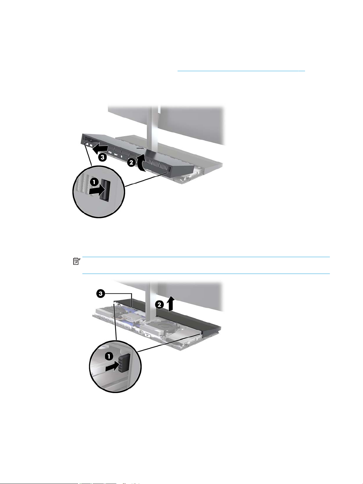
Base unit access covers
The base unit access covers must be removed to access internal computer components.
1. Prepare the computer for disassembly (see Preparing to disassemble the computer on page 17).
2. To remove the rear access cover, press the two release buttons on the rear of the base unit (1), and at
the same time rotate the rear of the cover up (2). Then slide the cover back to remove it from the base
(3).
3. To remove the front access cover after removing the rear access cover:
a. Press the two release buttons on the rear of the front cover (1) and lift the cover straight up (2) to
remove it.
NOTE: There is a cable connected to the right side of the front cover (3). Be careful not to pull the
cover up too far and cause the cable to disconnect.
18 Chapter 4 Removal and replacement procedures

b. Rotate the left side of the cover away from the base unit while being careful not to disconnect the
cable attached to the right side of the cover.
4. To replace the front access cover, press the cover straight down onto the base unit so that the cover
snaps in place.
IMPORTANT: Be sure to press this cover straight down. To avoid damaging components on the
underside of the cover, do not slide access cover into place.
5. To replace the rear access cover, slide tabs on the front of the rear cover under the slots on the rear of
the front cover (1), and then press the rear of the rear cover down (2). Make sure no wires or parts are
pinched as the cover is seated.
6. Reconnect the power cord and any external devices, and then turn on the computer.
Base unit access covers 19
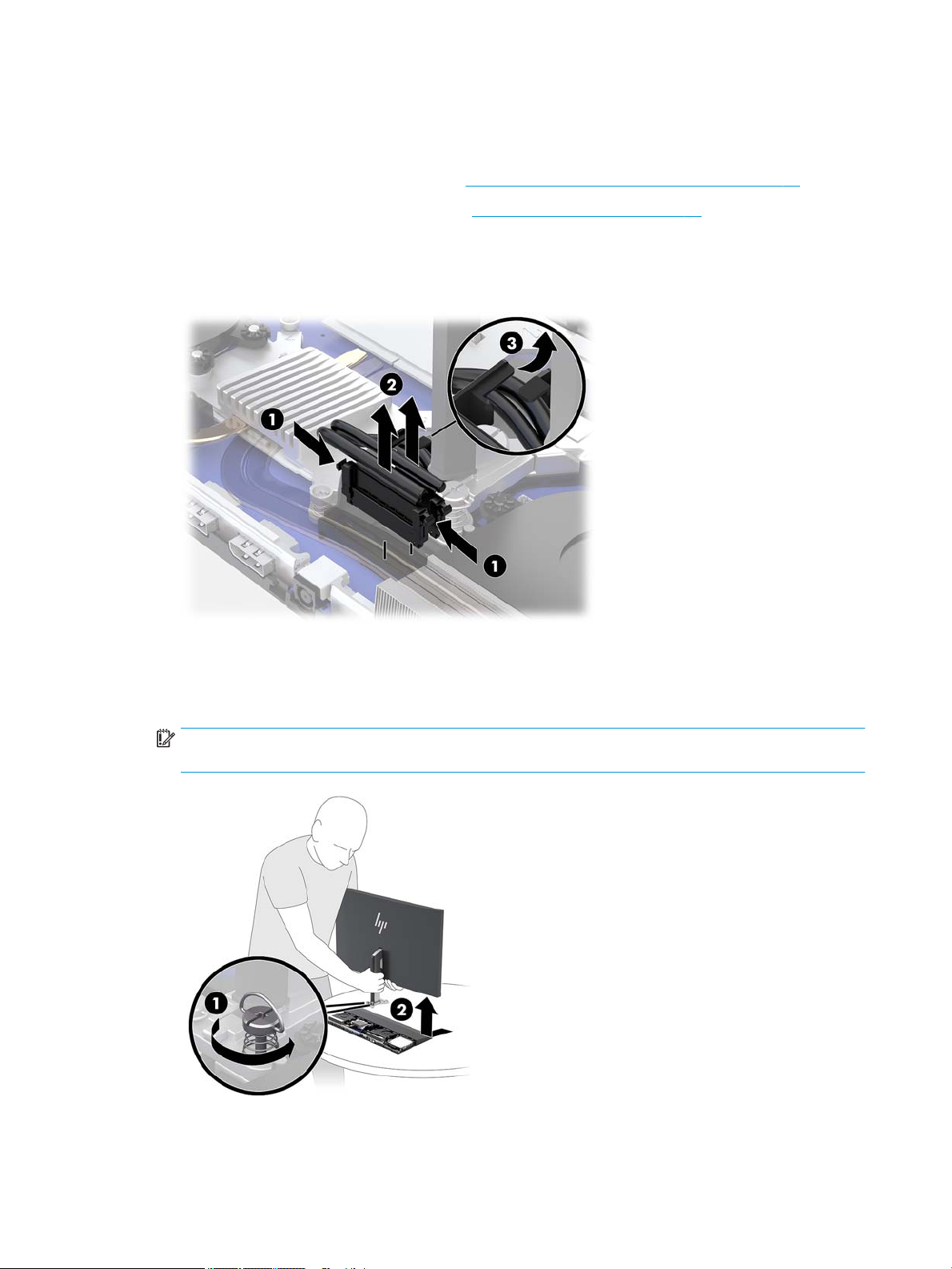
Display head
The display head can be replaced or upgraded to a dierent display.
1. Prepare the computer for disassembly (see Preparing to disassemble the computer on page 17).
2. Remove the base unit rear access cover (see Base unit access covers on page 18).
3. Disconnect the two display cables attached to the system board by squeezing inward on the two ends of
the cable connectors (1) and pulling the cable connectors up and o the system board (2).
4. Remove the cables from the clip (3).
5. As shown in the following illustration, loosen the two captive screws at the base of the display head’s
neck (1). While holding onto the bottom of the display head from the front with one hand, slide the
display head back with your other hand to clear it from the small metal retention tab, and then lift the
display o the base (2).
IMPORTANT: The display head is heavy. Make sure you are holding the display head rmly when
removing it to prevent the display head from falling over and being damaged.
To replace the display head, reverse the removal procedures.
20 Chapter 4 Removal and replacement procedures

Internal components
Components
(1) Hard drive (3) RTC battery
(2) M.2 SSD (under the fan) (4) Memory modules
Internal components 21

Memory
Description
16-GB
8-GB
4-GB
The memory slots on the system board can be populated with up to two industry-standard small outline dual
inline memory modules (SODIMMs). These memory slots are populated with at least one preinstalled memory
module.
Memory module specications
For proper system operation, the memory modules must meet the following qualications:
Component Specication
Memory modules 1.2 volt DDR4-SDRAM memory modules
Compliance Unbuered non-ECC DDR4-2400 MHZ–compliant
Pins Industry-standard 260 pins containing the mandatory Joint Electronic Device
Engineering Council (JEDEC) specication
Support Support CAS latency DDR4 2400 MHz (15–15–15 timing)
Slots 2
Maximum Memory 16 GB per memory slot, 32 GB total
Supported 4 Gbit and 8 Gbit non-ECC memory technologies single-sided and double-sided SODIMMs
Note The system will not operate properly if you install unsupported SODIMM
HP oers upgrade memory for this computer and advises that the consumer purchase it to avoid
compatibility issues with unsupported third-party memory.
Populating memory modules
Refer to the following table to identify the memory module channel locations.
Location System board label Channel
Lower Socket SODIMM1 Channel B
Upper Socket SODIMM3 Channel A
memory. SODIMMs constructed with x8 and x16 DDR devices are supported; memory
modules constructed with x4 SDRAM are not supported.
22 Chapter 4 Removal and replacement procedures
 Loading...