


 Loading...
HP Enterprise Modular Library E-Series
User Guide
HP Part Number: AH876-96010 Published: December 2012 Edition: 8th
© Copyright 2005, 2012 Hewlett-Packard Development Company, L.P.
The information contained herein is subject to change without notice. The only warranties for HP products and services are set forth in the express warranty statements accompanying such products and services. Nothing herein should be construed as constituting an additional warranty. HP shall not be liable for technical or editorial errors or omissions contained herein.

Contents |
|
1 Library overview......................................................................................... |
7 |
Available configurations............................................................................................................ |
7 |
Parts of the library.................................................................................................................. |
10 |
Base module.......................................................................................................................... |
11 |
Expansion modules................................................................................................................. |
13 |
Tape drive expansion module.............................................................................................. |
14 |
Card cage expansion module............................................................................................. |
14 |
Capacity expansion module................................................................................................ |
15 |
Controller cards...................................................................................................................... |
15 |
Library robotics controller.................................................................................................... |
16 |
Interface Manager card...................................................................................................... |
16 |
Interface controller ............................................................................................................ |
18 |
Ports on the e2400-FC 2Gb interface controller................................................................. |
18 |
Ports on the e2400-FC 4Gb interface controller................................................................. |
18 |
Changing the master controller (SIPP master)..................................................................... |
19 |
Functional description.............................................................................................................. |
19 |
Load ports and magazines...................................................................................................... |
20 |
Tape drives............................................................................................................................ |
21 |
Switch for the internal network.................................................................................................. |
21 |
Operator control panel............................................................................................................ |
22 |
Numbering............................................................................................................................ |
22 |
Command View TL.................................................................................................................. |
26 |
Library and Tape Tools............................................................................................................ |
27 |
2 Using the library...................................................................................... |
28 |
Powering on the library........................................................................................................... |
28 |
Powering off the library........................................................................................................... |
29 |
Center-door interlock............................................................................................................... |
29 |
Performing an inventory........................................................................................................... |
29 |
Attaching barcode labels to tape cartridges............................................................................... |
29 |
Setting the write-protect switch.................................................................................................. |
31 |
Inserting tape cartridges into the load port................................................................................. |
31 |
Using the OCP....................................................................................................................... |
32 |
OCP icons........................................................................................................................ |
32 |
Home screen..................................................................................................................... |
33 |
OCP tabs and status bar..................................................................................................... |
33 |
Timeouts........................................................................................................................... |
34 |
OCP functions................................................................................................................... |
35 |
Status screen..................................................................................................................... |
37 |
Configuration screen.......................................................................................................... |
39 |
Operations screen.............................................................................................................. |
40 |
Support screen.................................................................................................................. |
42 |
Controls and indicators........................................................................................................... |
42 |
Library robotics controller.................................................................................................... |
42 |
Interface Manager card...................................................................................................... |
43 |
e2400-FC 2Gb interface controller....................................................................................... |
44 |
e2400-FC 4Gb interface controller....................................................................................... |
44 |
LTO tape drives.................................................................................................................. |
45 |
Switch for the internal network............................................................................................. |
46 |
Library main power switch................................................................................................... |
47 |
Power supply in the base module or tape drive expansion module............................................ |
48 |
Power supply in the card cage expansion module.................................................................. |
48 |
Contents 3
Power distribution unit......................................................................................................... |
49 |
3 Troubleshooting and event reporting........................................................... |
50 |
Periodic and routine maintenance............................................................................................. |
50 |
Maintaining tape cartridges................................................................................................ |
50 |
Cleaning Ultrium tape drives............................................................................................... |
51 |
Diagnostic support tools.......................................................................................................... |
51 |
Troubleshooting...................................................................................................................... |
51 |
Startup problems............................................................................................................... |
53 |
OCP problems................................................................................................................... |
55 |
Robotics problems.............................................................................................................. |
55 |
Operating problems........................................................................................................... |
57 |
Tape drive problems........................................................................................................... |
57 |
Interface Manager card problems........................................................................................ |
58 |
Interface controller problems............................................................................................... |
61 |
LED indicators............................................................................................................... |
61 |
Basic troubleshooting..................................................................................................... |
61 |
Examining FC port connection................................................................................... |
62 |
Examining the interface controller configuration............................................................ |
62 |
Examining devices.................................................................................................... |
62 |
Examining the host configuration................................................................................ |
62 |
Examining HBA device driver information.................................................................... |
62 |
Examining serial port configuration............................................................................. |
62 |
4 Removing and replacing parts.................................................................... |
64 |
Interface Manager card........................................................................................................... |
64 |
Required tools................................................................................................................... |
64 |
Interface Manager card 342213-001 or 393531-001.............................................................. |
64 |
Removing the Interface Manager card 342213-001 or 393531-001...................................... |
64 |
Replacing the Interface Manager card 342213-001 or 393531-001...................................... |
66 |
Interface Manager card 480240-001................................................................................... |
67 |
Removing the Interface Manager card480240-001............................................................ |
67 |
Replacing the Interface Manager card 480240-001.......................................................... |
68 |
Power supply in the base module or tape drive expansion module................................................ |
69 |
Required tools................................................................................................................... |
69 |
Removing a power supply from the base module or tape drive expansion module...................... |
69 |
Replacing a power supply in the base module or tape drive expansion module.......................... |
70 |
Power supply in the card cage expansion module ...................................................................... |
70 |
Required tools................................................................................................................... |
71 |
Removing a power supply from the card cage expansion module ............................................ |
71 |
Replacing a power supply in the card cage expansion module ............................................... |
71 |
LTO2 or LTO3 tape drive.......................................................................................................... |
72 |
Required tools................................................................................................................... |
72 |
Removing an LTO2 or LTO3 tape drive.................................................................................. |
72 |
Replacing an LTO2 or LTO3 tape drive.................................................................................. |
72 |
LTO4 and later tape drives....................................................................................................... |
73 |
Load port magazine............................................................................................................... |
75 |
Removing a load port magazine.......................................................................................... |
75 |
Replacing a load port magazine.......................................................................................... |
75 |
5 Moving the library.................................................................................... |
77 |
Selecting an installation location............................................................................................... |
77 |
Preparing the library for a short move....................................................................................... |
77 |
Preparing the library for long-distance relocation........................................................................ |
77 |
Repacking the library.............................................................................................................. |
78 |
Preparing the library for operation............................................................................................ |
79 |
4Contents
6 Support and other resources...................................................................... |
80 |
Contacting HP........................................................................................................................ |
80 |
Related information................................................................................................................. |
80 |
Related documentation....................................................................................................... |
80 |
HP websites...................................................................................................................... |
80 |
HP tape cartridges........................................................................................................ |
81 |
Product warranties......................................................................................................... |
81 |
Subscription services...................................................................................................... |
81 |
Typographic conventions......................................................................................................... |
81 |
Updated regulatory compliance and recycling notices................................................................. |
82 |
7 Documentation feedback........................................................................... |
83 |
A Specifications and characteristics............................................................... |
84 |
Library component specifications.............................................................................................. |
84 |
Library environmental specifications.......................................................................................... |
85 |
Acoustics............................................................................................................................... |
86 |
Ultrium tape drive comparisons................................................................................................. |
86 |
B Regulatory statements................................................................................ |
87 |
Federal Communications Commission notice.............................................................................. |
87 |
FCC rating label................................................................................................................ |
87 |
Class A equipment........................................................................................................ |
87 |
Class B equipment........................................................................................................ |
87 |
Declaration of Conformity for products marked with the FCC logo, United States only................. |
87 |
Modification..................................................................................................................... |
88 |
Cables............................................................................................................................. |
88 |
Canadian notice (Avis Canadien)............................................................................................. |
88 |
Class A equipment............................................................................................................. |
88 |
Class B equipment............................................................................................................. |
88 |
European Union notice............................................................................................................ |
88 |
Japanese notices.................................................................................................................... |
88 |
Japanese VCCI-A notice...................................................................................................... |
88 |
Japanese VCCI-B notice...................................................................................................... |
89 |
Japanese power cord statement........................................................................................... |
89 |
Korean notices....................................................................................................................... |
89 |
Class A equipment............................................................................................................. |
89 |
Class B equipment............................................................................................................. |
89 |
Taiwanese notices................................................................................................................... |
89 |
BSMI Class A notice........................................................................................................... |
89 |
Taiwan battery recycle statement.......................................................................................... |
90 |
Turkish recycling notice............................................................................................................ |
90 |
Laser compliance notices......................................................................................................... |
91 |
English laser notice............................................................................................................ |
91 |
Dutch laser notice.............................................................................................................. |
91 |
French laser notice............................................................................................................. |
91 |
German laser notice........................................................................................................... |
92 |
Italian laser notice.............................................................................................................. |
92 |
Japanese laser notice......................................................................................................... |
92 |
Spanish laser notice........................................................................................................... |
93 |
Recycling notices.................................................................................................................... |
93 |
English recycling notice...................................................................................................... |
93 |
Bulgarian recycling notice................................................................................................... |
94 |
Czech recycling notice........................................................................................................ |
94 |
Danish recycling notice....................................................................................................... |
94 |
Dutch recycling notice......................................................................................................... |
94 |
Contents 5
Estonian recycling notice..................................................................................................... |
95 |
Finnish recycling notice....................................................................................................... |
95 |
French recycling notice....................................................................................................... |
95 |
German recycling notice..................................................................................................... |
95 |
Greek recycling notice........................................................................................................ |
96 |
Hungarian recycling notice................................................................................................. |
96 |
Italian recycling notice........................................................................................................ |
96 |
Latvian recycling notice....................................................................................................... |
96 |
Lithuanian recycling notice.................................................................................................. |
97 |
Polish recycling notice......................................................................................................... |
97 |
Portuguese recycling notice................................................................................................. |
97 |
Romanian recycling notice.................................................................................................. |
97 |
Slovak recycling notice....................................................................................................... |
98 |
Spanish recycling notice..................................................................................................... |
98 |
Swedish recycling notice..................................................................................................... |
98 |
Battery replacement notices..................................................................................................... |
98 |
Dutch battery notice........................................................................................................... |
98 |
French battery notice.......................................................................................................... |
99 |
German battery notice........................................................................................................ |
99 |
Italian battery notice........................................................................................................ |
100 |
Japanese battery notice.................................................................................................... |
100 |
Spanish battery notice...................................................................................................... |
101 |
C Ordering HP tape cartridges and barcode label packs............................... |
102 |
Where to buy tape cartridges and barcode labels.................................................................... |
102 |
Part numbers for tape cartridges and barcode labels................................................................. |
102 |
D Installing a redundant PDU...................................................................... |
104 |
PDU components.................................................................................................................. |
104 |
Leakage current.................................................................................................................... |
104 |
Redundancy......................................................................................................................... |
104 |
Power rating........................................................................................................................ |
104 |
Placement of redundant PDU components................................................................................ |
105 |
Installation of redundant PDU components............................................................................... |
105 |
Glossary.................................................................................................. |
106 |
Index....................................................................................................... |
109 |
6Contents

1 Library overview
The HP Enterprise Modular Library (EML) E-Series Tape Libraries provide performance, reliability and investment protection for your data protection needs. With up to 16 HP LTO tape drives, the EML E-Series boasts native throughput of over 6.9 TB/hr. Based on the HP Extended Tape Library Architecture (ETLA), controllers help to ensure that rogue I/O requests do not interrupt the backup or recovery job in progress. Additionally, the hardware itself is very reliable, designed for 24x7 environments. Investment protection is achieved through the addition of expansion modules, the EML E-Series library scales within the library footprint to 16 drives and 442 slots for maximum performance, or 8 drives and 505 slots for maximum capacity.
The EML E-Series Tape Libraries contain the following features:
•Scalable capacity from 71 slots to 505 slots
•Scalable performance up to 16 Ultrium tape drives with 442 slots
•Interface controllers protect tape drives from SAN events
•Remote management via Command View for Tape Libraries software or the command line interface
•Easy to use touch screen graphical user interface
•User configurable load ports with removable magazines
•Certified under the HP Enterprise Backup Solution (EBS)
•Factory and field rack configurations
•2,000,000 mean swaps between failure
Available configurations
You can order the library in the following configurations.
Table 1 EML configurations
Configuration |
Illustration Height in |
Maximum |
Configurable |
Configurable |
Number of |
|
“U” |
slots |
load port |
reserved |
possible |
|
|
available |
slots (in |
slots |
tape drives |
|
|
|
multiples of |
|
|
|
|
|
5) |
|
|
71e1 base modulefield racked |
12 |
71 |
0–5 |
0 |
1–4 |
103e1 base modulefactory |
12 |
103 |
0–5 |
0–9 |
1–4 |
racked |
|
|
|
|
|
Available configurations |
7 |

 Table 1 EML configurations (continued)
Configuration |
Illustration Height in |
Maximum |
Configurable |
Configurable |
Number of |
|
“U” |
slots |
load port |
reserved |
possible |
|
|
available |
slots (in |
slots |
tape drives |
|
|
|
multiples of |
|
|
|
|
|
5) |
|
|
245e1 base module1 tape drive |
24 |
245 |
0–15 |
0–9 |
1–8 |
expansion module1 card cage |
|
|
|
|
|
expansion modulefactory racked |
|
|
|
|
|
348e1 base module2 tape drive |
32 |
348 |
0–25 |
0–9 |
1–12 |
expansion modules1 card cage expansion modulefactory racked
375e1 base module1 tape drive |
32 |
375 |
0–25 |
0–9 |
1–8 |
expansion module1 card cage expansion module1 capacity expansion modulefactory racked
442e1 base module3 tape drive |
40 |
442 |
0–35 |
0–9 |
1–16 |
expansion modules1 card cage expansion modulefactory racked
8Library overview

 Table 1 EML configurations (continued)
Configuration |
Illustration Height in |
Maximum |
Configurable |
Configurable |
Number of |
|
“U” |
slots |
load port |
reserved |
possible |
|
|
available |
slots (in |
slots |
tape drives |
|
|
|
multiples of |
|
|
|
|
|
5) |
|
|
469e1 base module2 tape drive |
40 |
469 |
0–35 |
0–9 |
1–12 |
expansion modules1 card cage |
|
|
|
|
|
expansion module1 capacity |
|
|
|
|
|
expansion modulefactory racked |
|
|
|
|
|
505e1 base module1 tape drive |
40 |
505 |
0–35 |
0–9 |
1–8 |
expansion module1 card cage expansion module2 capacity expansion modulesfactory racked
Available configurations |
9 |
Parts of the library
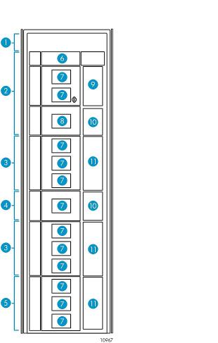
The following figures show the parts of a 469e library. See (page 7).
Figure 1 Front view of the library
1. Reserved space. If your library contains LTO4 or later |
2. Base module |
|
tape drives, this space contains the switch for the internal |
|
|
network. |
|
|
3. |
Tape drive expansion module |
4. Card cage expansion module |
5. |
Capacity expansion module |
6. Robotics unit |
7. Viewing windows |
8. Operator control panel (OCP) |
|
9. 5-Cartridge load port |
10. 4U blank covers |
|
11. 10-Cartridge load ports |
|
|
10 Library overview
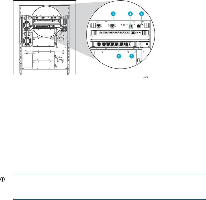
Figure 2 Rear view of the library
1. Reserved space |
2. Switch for the internal network (in libraries with LTO4 or |
|
|
|
later tape drives only) |
3. |
Base module |
4. Tape drive expansion module |
5. |
Card cage expansion module |
6. Capacity expansion module |
7. Main power switch |
8. Base module card cage (e2400-FC 2Gb interface |
|
|
|
controller shown) |
9. Tape drives (LTO3 tape drives shown) |
10. Cable management features |
|
11. Fans |
12. Power supplies |
|
13. Power strips |
14. Power distribution unit (PDU) |
|
Base module
The 12U base module (see (page 10) and (page 11)) resides at the top of the library below the 2U reserved space or the switch for the internal network.
In the EML 71e, the base module contains a total of 71 LTO slots. Five slots within a load port are configurable as either import/export slots or storage slots. No reserved slots are available.
In all other EML configurations, the base module contains a total of 103 LTO slots. Five slots are configurable as either import/export slots or storage slots within a load port through the use of a removable magazine. You can configure 9 slots as reserved. A common use for reserved slots is for holding cleaning cartridges. The number of usable permanent slots depends on whether it is the bottom module in the library because the library floor is always attached to the bottom module
Base module |
11 |

and the floor limits the distance that the robot can travel. If the library floor is attached to the base module, the bottom two rows (containing 16 slots) cannot be used.
The robotics unit is located at the top of the base module. When fully retracted (or parked), the robot is fully contained within a 2U space. For safety reasons, the robot is parked before the center door can be opened.
Within the robot, a lift table assembly contains a motor, pulleys, and cables to move the table up and down to a specific level in the library. The picker assembly moves front and back, and side-to-side along the table. A barcode scanner, attached to the bottom of the picker assembly, scans targets on rack components for alignment, as well as barcode labels on tape cartridges, if they are present. The picker has fingers that remove and insert tape cartridges among storage slots, tape drives, or load ports.
Figure 3 Robotics unit
1. |
Robotics unit |
2. Lift-flex retraction handle |
|
3. |
Ratchet tool |
4. |
Robot picker |
5. |
Lift suspension cable |
6. Table assembly |
|
7. |
Lift pole |
8. |
Lift-flex cable |
The base module has two windows on the front for viewing the robotic motion inside the library. A load port door is located to the right front (see (page 10)) where a 5-cartridge magazine can be loaded with tape cartridges for insertion into or removal from the library. The load ports are mechanical devices that enable you to import and export tape cartridges to and from the library through removable magazines, or act as additional library storage slots. These two functions for a load port cannot be mixed; you must either designate an entire load port to be import/export slots or storage slots. The base module contains a load port capable of using one 5-cartridge magazine. An operator control panel (OCP) is located at the bottom front of the base module.
The base module contains an autoranging power supply (a redundant power supply is optional), card cage, cable management features, and space for mounting up to four LTO-technology tape drives on the back.
12 Library overview
The card cage in the base module (see (page 13)) provides six cPCI slots for the following:
•Library robotics controller (see (page 16)) A single slot, 6U-wide cPCI board having Ethernet ports and an RS-232 port. One Ethernet port connects this controller to the Interface Manager card.
•Interface Manager card (see (page 16)) A single slot, 4U-wide cPCI board having six Ethernet ports. This board contains 128MB of dynamic random access memory (DRAM) plus a 256MB CompactFlash memory card, both in their own sockets. A 2U-wide adapter panel next to the 4U-wide Interface Manager card enables it to fit in the lowest 6U-wide card cage slot.
•Interface controller A cPCI board, having two FC ports for connecting to the SAN, along with four FC ports for connecting up to four HP LTO2 or LTO3 tape drives. LTO4 and later tape drives do not connect to the interface controller; instead, they connect directly to the SAN. The interface controller is available in two speeds. The e2400-FC 2Gb interface controller has an FC speed of 2 Gbps, is 6U wide, and uses a single slot (see (page 18)). The e2400-FC 4Gb interface controller has an FC speed of 4 Gbps, is 4U wide, and uses two slots (see (page 18)).
Figure 4 Base module card cage (LTO3 tape drives shown)
1. Base module card cage |
2. Interface Manager card |
|
3. |
Interface controller (e2400-FC 2Gb interface controller |
4. Library robotics controller |
shown) |
|
|
5. |
Adapter panel |
|
The cable management feature is a spool, mounted near the tape drives, that enables LAN and FC cables to be dressed and routed away from hot plug or hot swap components.
Expansion modules
Three expansion modules are available to increase library capacity beyond that provided by the base module. These expansions modules are:
•Tape drive expansion module
•Card cage expansion module
•Capacity expansion module
IMPORTANT: If you are adding expansion modules to an EML 71e, you must purchase a capacity upgrade license for Command View TL (part number AH063A). This license upgrades your base module from 71 slots to 103 slots. You must also make sure that your rack has side panels and doors installed to comply with regulatory requirements.
Expansion modules 13

Tape drive expansion module
The tape drive expansion module is an 8U chassis containing 94 LTO slots (84 permanent and 10 configurable). The number of usable permanent slots depends on whether it is the bottom module in the library because the library floor is always attached to the bottom module and the floor limits the distance that the robot can travel. If the library floor is attached to the tape drive expansion module, the bottom row (containing seven slots) cannot be used.
CAUTION: Never operate the library with the floor removed. The robot can be damaged.
The tape drive expansion module has three windows on the front for viewing the robotic motion inside the library. To the right is a 10-cartridge configurable load port that holds two 5-cartridge magazines.
On the back, the module contains one primary power supply with a slot provided for another optional redundant power supply. Up to four Ultrium tape drives can be installed in the tape drive expansion module. Cable management features are provided for cable routing and dressing.
Figure 5 Tape drive expansion module
1. Viewing windows |
2. 10-Cartridge load port |
3. Power supplies (optional redundant power supply shown) |
4. Tape drives (LTO3 tape drives shown) |
5. Cable management features |
|
Card cage expansion module
The card cage expansion module is a 4U chassis that contains 48 permanent LTO slots and space for additional interface controllers. This module must be located directly below the top 8U tape drive expansion module. The number of usable permanent slots depends on whether it is the bottom module in the library because the library floor is always attached to the bottom module and the floor limits the distance that the robot can travel. If the library floor is attached to the card cage expansion module, the last two rows (containing 16 slots) cannot be used.
CAUTION: Never operate the library with the floor removed. The robot can be damaged.
The front of the card cage expansion module has one window for viewing robotic motion inside the library. On the back, six PCI card slots are available for additional interface controllers to expand the library tape drive capacity. One interface controller is added for every four additional LTO2 or LTO3 tape drives. LTO4 and later tape drives do not connect to an interface controller; instead, they connect directly to the SAN. Two power supplies are located at the bottom of the card cage, and two cooling fans are on the right.
14 Library overview

Figure 6 Card cage expansion module
1. Viewing window |
2. 4U blank cover |
|
3. |
Card slots |
4. Power supplies |
5. |
Fans |
|
Capacity expansion module
The capacity expansion module is an 8U chassis containing 120 LTO slots (110 permanent and 10 configurable). If the library floor is attached to the capacity expansion module, the bottom row containing 10 slots is blocked and cannot be used.
CAUTION: Never operate the library with the floor removed. The robot can be damaged.
If the capacity expansion module is placed below the base module or a tape drive expansion module, six slots at the top of the back wall cannot be used because the tape drives in the module above it prevent the robot from reaching these slots.
On the front of the capacity expansion module are three windows for viewing the robotic motion inside the library. To the right is a 10-cartridge configurable load port that holds two 5-cartridge magazines.
On the back of the capacity expansion module are cable management features for cable routing and dressing.
Figure 7 Capacity expansion module
1. Viewing windows |
2. 10-Cartridge load port |
3. Cable management features
Controller cards
This section explains the function of the three major cards that control the library. These cards are:
•Library robotics controller
•Interface Manager card
•Interface controller
Controller cards 15
Library robotics controller
The library robotics controller contains firmware to control the robot, communicate with the Interface Manager card, manage the library servo and vision control, and monitor the door and load port sensor status.
Robot commands are sent from hosts in the SAN to an interface controller, which directs them over an internal Ethernet network to the library robotics controller. The library robotics controller translates these commands into movements to be performed by the robot.
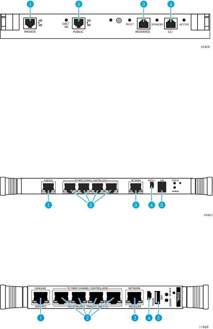
Figure 8 Ports on the library robotics controller
1. Private Ethernet port (not used)
3. Reserved port (not used)
2. Public Ethernet port (connection to Interface Manager card)
4. CLI port (RS-232–HP services only)
Interface Manager card
The Interface Manager card is an HP proprietary management card designed to consolidate and simplify the management of multiple interface controllers installed in the library. It also provides SAN-related diagnostics and management for library components, including the interface controllers, tape drives, and robotics. The Interface Manager card, in conjunction with HP Command View TL software, provides remote management of the library by using a serial, Telnet, or Web-based graphical user interface (GUI).
Figure 9 Ports on the Interface Manager card 342213–001 or 393531–001
1. Cascade Ethernet port (connection to library robotics |
2. Private Ethernet ports to interface controllers |
|
controller) |
|
|
3. |
Network Ethernet port (to management station) |
4. Serial port |
5. |
Auxiliary RJ-11 serial connector (not used) |
|
Figure 10 Ports on the Interface Manager card 480240-001
1. Cascade Ethernet port (connection to library robotics |
2. Private Ethernet ports to interface controllers |
|
controller) |
|
|
3. |
Network Ethernet port (to management station) |
4. Serial port |
5. |
USB port |
|
16 Library overview
The Interface Manager card communicates with the management station over the LAN. The management station is a Microsoft Windows-based PC (server) that hosts the Command View TL software. Ideally, the management station should have a static IP address, and be dedicated for use with the Interface Manager card and Command View TL software.
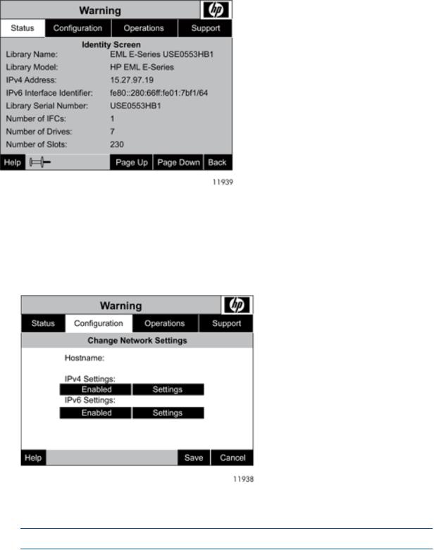
IP connections on the EML can be IPv4 or IPv6 format. The library can be configured to use one or both formats, but can not operate if neither protocol is enabled. View the IP connections on the Identity Screen (from the Home screen select Status, then Identity Screen).
Figure 11 Viewing IP connections from the Identity Screen
Enable or disable the protocols from the Change Network Settings screen, then view and save the settings from that same screen.
To view and change the settings for either IPv4 or IPv6:
1.From the Home screen, select Configuration.
2.From the Library Configuration menu select Change Network Settings.
Figure 12 Viewing the Change Network Settings screen
3.To enable or disable IPv4 or IPv6, touch the appropriate Enable or Disable button.
4.To view or change the settings, touch the appropriate Settings button.
NOTE: Some settings are read-only.
Controller cards 17

5.To save any changes to the network settings, select the Save button at the bottom, right of the OCP.
Any client machine on the LAN can communicate with the Interface Manager card either through the GUI or through a command line interface (CLI). At a higher level, multiple libraries, each containing an Interface Manager card, can be connected to a single management station. Each Interface Manager card can communicate with only one management station, but the management station can communicate with multiple Interface Manager cards.
After being configured, the Interface Manager card is used to configure the interface controllers based on knowledge of the library and SAN. As robotics commands are received from the interface controllers, the Interface Manager card acts as a switch to relay these commands to the library robotics controller. The Interface Manager card contains on-board Flash memory to provide a persistent history of the library and storage network health.
Interface controller
The interface controller is an HP proprietary card that provides FC connectivity for LTO2 and LTO3 tape drives and robotics in the SAN. Commands, data, and status information are transferred to and from this controller, from hosts, the robot, and the LTO2 and LTO3 tape drives. One interface controller can manage up to four LTO2 or LTO3 tape drives.
LTO4 and later tape drives do not connect to an interface controller; instead, they connect directly to the SAN. Libraries that contain only LTO4 or later tape drives still need one interface controller which is used to direct commands to the robot. The interface controller is available in two speeds: 2 Gbps and 4 Gbps.
Ports on the e2400-FC 2Gb interface controller
Figure 13 Ports on the e2400-FC 2Gb interface controller
1. FC ports to LTO2 and LTO3 tape drives |
2. FC ports to hosts |
3. Ethernet port (connection to Interface Manager card) |
4. Serial port |
Ports on the e2400-FC 4Gb interface controller
Figure 14 Ports on the e2400-FC 4Gb interface controller
1. FC ports to LTO2 and LTO3 tape drives |
2. FC ports to hosts |
3. Ethernet port (connection to Interface Manager card) |
4. Serial port |
18 Library overview
Changing the master controller (SIPP master)
One interface controller is assigned by the Interface Manager card as the master controller the SIPP master. Only the SIPP master is designated to send commands to the library robotics controller. If multiple interface controllers are present, Command View TL software, through the Cabling View, can be used to determine which one is acting as the SIPP master. Changing the SIPP master requires a service-level password and command using the CLI (Telnet or serial). The commands are:
SERVICE L&TTPASSWORD
SET IPCONNECTION INTERFACE MASTER X
, if the IM firmware is i182 or lower
SERVICE L&TTPASSWORD
SET IPCONNECTION MASTER X
, if the IM firmware is I200 or higher
where L&TTPASSWORD is the Library and Tape Tools (L&TT) password and X is the interface controller number. Obtain the password from the web site L&TT web siteby calling HP Support to get a 2–day ltt service password. Find the interface controller number by using the SHOW INTERFACE INFO ALL CLI command.
If the master interface controller (designated SIPP master) is replaced, the Hardware Replacement wizard sets up the SIPP master. If the master interface controller (designated SIPP master) is moved to another interface controller in the library, perform the following manual service steps:
1.Remove all partitions.
2.Remove all host maps.
3.Log in to the CLI and obtain service-level access.
4.Use the SET IPCONNECTION MASTER X command to make a particular interface controller the SIPP master. Currently, the Interface Manager card does not automatically failover an interface controller, even if the previous SIPP master is missing.
5.Reconfigure maps and partitions.
Functional description
The library receives commands and data throughout the SAN from hosts running applications from approved independent software vendors (ISVs). Host bus adapters (HBAs) in servers send this traffic over FC links, usually through FC switches. For LTO4 and later tape drives, the traffic goes directly to the tape drive; but for LTO2 and LTO3 tape drives, the traffic first goes through an interface controller. One interface controller can connect up to four LTO2 or LTO3 tape drives. For all libraries, regardless of whether they contain LTO2 and LTO3 or LTO4 and later tape drives, at least one interface controller is required to pass tape cartridge changer (robotics) commands to the Interface Manager card over a private network. The Interface Manager card passes these SCSI commands on to the library robotics controller over the private network, taking advantage of the error handling and retry capabilities of TCP/IP.
Functional description |
19 |

Figure 15 Library network
1. Hosts |
2. FC Switch (SAN) |
|
3. |
Interface controller |
4. Interface Manager card |
5. |
LTO2 or LTO3 tape drives |
6. Library robotics controller |
7. Robot |
8. OCP |
|
9. Serial connection |
10. Telnet connection |
|
11. Management station |
12. Library boundary |
|
13. LTO4 and later tape drives |
14. Switch for the internal network |
|
In addition to receiving traffic from the interface controllers, the Interface Manager card receives command and diagnostic requests over an Ethernet connection from three other possible sources. The majority of requests come from a management station where Command View TL software resides. The other two sources are through a Telnet session or a serial interface. The Interface Manager card works in the background to manage library functions. It configures the interface controllers to direct commands from host systems to the appropriate LTO2 or LTO3 tape drive or to the library robotics controller.
The library robotics controller receives commands over an internal private network and from the OCP. It manages robotics movement, monitors the door and load port sensor status, and stores library information in volatile memory.
Load ports and magazines
The load ports are mechanical devices on the front of the library that enable you to import and export tape cartridges to and from the library through removable magazines, or act as additional library storage slots. These two functions for a load port cannot be mixed; you must either designate an entire load port to be import/export slots or storage slots. The base module contains a load port capable of using one 5-cartridge magazine. The 8U expansion modules contain load ports capable of using two 5-cartridge magazines each.
20 Library overview
Figure 16 Library load ports on 40U configuration
Tape drives
The Ultrium tape drive is a high performance streaming tape drive that uses LTO technology. The library can use Ultrium 460 (LTO 2), Ultrium 960 (LTO 3), Ultrium 1840 (LTO4), Ultrium 3280 (LTO5) and Ultrium 6650 (LTO6) tape drives.
The Ultrium 960 and later include support for both rewriteable and Write-Once, Read-Many (WORM) tape cartridges. WORM tape cartridges provide an enhanced level of data security against alteration of data because you cannot erase or overwrite them. To check whether your backup or archive software application supports WORM tape cartridges, see the following web site: http://www.hp.com/go/connect.
For optimum performance, always use a tape cartridge that matches the specifications of your tape drive. You can find comparisons between the Ultrium tape drives in (page 86).
Tape cartridges and cleaning cartridges are specifically formatted for use with Ultrium drives. To order Ultrium tape cartridges, see “Ordering HP tape cartridges and barcode label packs” (page 102).
Switch for the internal network
CAUTION: Do not connect this switch to your local LAN. It is for internal library use only. Connecting this switch to the LAN could cause library components to perform incorrectly or report failures.
The 24-port Ethernet switch provides a private management network to connect the Interface Manager card to the LTO4 or later tape drives. You must install one switch in each library that contains LTO4 or later tape drives.
Tape drives 21

Figure 17 Ports on the switch for the internal network
1. 10/100Base-TX RJ-45 ports
Operator control panel
The OCP displays library status information and enables you to access the library menus with a touch screen. Use these menus to view and change the library settings, move tape cartridges, obtain status information, or run diagnostic tests. Functions provided by the OCP are:
•Robotic and tape drive firmware revision reporting
•Library configuration
•Library and tape drive serial number reporting
•Critical component status report
•Critical component failure notification
•Ability to move tapes to and from any location
•Ability to configure barcode label length and justification reporting to the front panel and to the host
•Access to error information
•Adjust screen contrast
Figure 18 Location of the OCP
Numbering
All of the tape cartridge slots and tape drives in a library are numbered with a coordinate system. You might see these numbers in your application software or in error or diagnostic messages. Error
22 Library overview

messages often include a slot location in the format MRC x,y,z. This identifies a module (x), row (y), and column (z) location.
Each module has a different number of available slots, but a common numbering scheme for identifying the slot location.
The library numbers the LTO slots using the following scheme:
•In general, the library numbers the slots one module at a time, starting with the top module. For slot numbering purposes, the 12U base module is considered to be two modules: an 8U base module and a 4U base module.
•Within each module, column numbering starts with 1 at the left column as viewed from the front of the library.
•Within each module, row numbering starts with 1 at the top row.
•Any reserved slots, located in the first column of the 8U base module, and taking up as many as nine slots, are not included in the numbering scheme. A common use for reserved slots is for holding cleaning cartridges.
NOTE: Reserved slots are not available on the EML 71e.
•If the load port slots are configured as import/export slots, they are skipped and not counted in the numbering of storage slots. If the load port slots are instead configured as storage slots, they are counted in the numbering scheme.
NOTE: Reconfiguring the load port slots for either import/export or storage changes the slot numbering in any lower modules the next time you perform an inventory.
•Some slots are not available in the bottom module in the library because the floor limits the distance that the robot can travel.
CAUTION: Never operate the library with the floor removed. The robot can be damaged.
The slot numbering for various modules are shown on the following pages:
•Base module of the EML 71e ((page 24))
•Base module of all other configurations ((page 25))
•Tape drive expansion module ((page 25))
•Card cage expansion module ((page 26))
•Capacity expansion module ((page 26))
Numbering 23
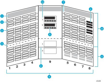
Figure 19 Slot numbering in the base module for the EML 71e
1. Robot park zone |
2. Array targets for the barcode scanner |
|
3. |
Slots available for data cartridges |
4. Software demarcation between upper and lower modules |
|
|
for slot counting purposes |
5. |
Tape drives |
6. Expansion identification label |
7. Row numbering |
8. Column numbering |
|
9. Load port slots |
10. 8U base module |
|
11. 4U base module |
12. Tape drive numbering |
|
24 Library overview

Figure 20 Slot numbering in the base module for all other EML configurations
1. Robot park zone
3. Reserved slots-can be used for cleaning cartridges or data cartridges
5. Slots available for data cartridges
7. Tape drives
9. Row numbering
11. Load port slots
13. 4U base module
2. Array targets for the barcode scanner
4. Software demarcation between upper and lower modules for slot counting purposes
6. Slots unavailable for use when the library floor is installed in this module
8. Expansion identification label
10. Column numbering
12. 8U base module
14. Tape drive numbering
Figure 21 Slot numbering in the tape drive expansion module
1. Slots available for data cartridges |
2. Array targets |
3. Slots unavailable for use when the library floor is installed |
4. Tape drive numbering |
in this module |
|
5. Tape drives |
6. Expansion identification label |
7. Row numbering |
8. Column numbering |
9. Load port slots |
|
Numbering 25

Figure 22 Slot numbering in the card cage expansion module
1. Slots available for data cartridges |
2. Array targets |
3. Slots unavailable for use when the library floor is installed 4. Expansion identification label in this module
5. Row numbering |
6. Column numbering |
Figure 23 Slot numbering in the capacity expansion module
1. Slots available for data cartridges
3. Slots unavailable for use when the library floor is installed in this module
5. Row numbering
7. Load port slots
2. Array targets
4. Slots unavailable for use when a base module or tape drive expansion module is above this module
6. Column numbering
Command View TL
Command View TL provides a browser-based GUI for remote management and monitoring of the Interface Manager card through a LAN. Command View TL is the preferred method for controlling the Interface Manager card. In conjunction with the Interface Manager card, Command View TL provides the following:
•Configuration and management of the Interface Manager card and FC interface controllers
•Management of the entire library system
•Hardware inventory and identity information
•Status information for connected hardware
•Error reporting and comprehensive error logs
•Firmware management
•License management
Command View TL is installed on a management station and communicates with the Interface Manager card through the LAN. The management station processes information from the Interface Manager card and serves up the Command View TL GUI. You can access Command View TL from
26 Library overview

the management station directly, or through any client on the LAN using a browser-based GUI. Multiple Command View TL clients can be simultaneously open across the LAN, and multiple libraries can be managed through the Command View TL software.
See the Command View TL documentation at http://www.hp.com/support/cvtl for prerequisites, installation, and operating instructions.
IMPORTANT: If you are upgrading an EML 71e, you must purchase a capacity upgrade license for Command View TL (part number AH063A). This license upgrades your base module from 71 slots to 103 slots.
Library and Tape Tools
Library and Tape Tools (L&TT) is a collection of storage hardware management and diagnostic tools assembled into a single, convenient program. L&TT offers a GUI or command screen interface (CSI), enabling you to perform the following functions with the library:
•Installation check Guides you through a basic installation check of the library. The software helps you choose an appropriate HBA, making sure that the device is detected by the system, and verifying key device functionality.
•Device identification Identifies the storage products connected to the system, along with key information on product configuration and status.
•Troubleshooting tests Provides various tests to verify product functionality or to isolate product issues. Tests include device self-tests, read/write tests on tape drives, exerciser tests for autoloaders and libraries, and specific device utilities.
•Support ticket generation If you experience a problem with a storage product, L&TT can generate a support ticket that includes essential information for troubleshooting the problem.
•Automatic notification of Web updates If a connection to the Internet is present and Web updates are enabled in the tool preferences, L&TT automatically informs you of the following updates, if available, each time the program is started:
◦New versions of L&TT
◦New firmware files for connected devices
◦New device-specific functionality (such as new or updated tests) for connected devices For more information on L&TT, go to the web site http://www.hp.com/support/tapetools.
Library and Tape Tools 27
2 Using the library
This chapter describes operating procedures for the library.
Powering on the library
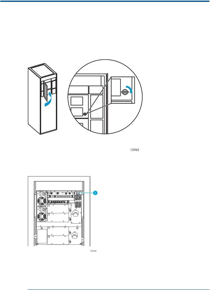
1.Close the center door of the library and turn the center-door knob one-quarter turn clockwise to lock it.
Figure 24 Closing the center door
2.At the back of the library, press the library main power switch to the I (On) position.
Figure 25 Library main power switch control
1. Library main power switch
NOTE: The following step applies only when the library is powered on for the first time or when a new interface controller is installed. This step is necessary to put the interface controller into managed mode.
28 Using the library

3.If this is the first time the library has been powered on after delivery, or if a new interface controller was installed, configure the interface controller so that it is recognized by the Interface Manager card. Do one of the following:
•If your library has an e2400-FC 2Gb interface controller, wait approximately two minutes, and turn off the main power switch. Wait several seconds and then turn on the power switch again.
•If your library has an e2400-FC 4Gb interface controller, reset the interface controller twice. To reset the interface controller, insert a paper clip into the reset hole. After resetting the interface controller, wait three minutes, then reset it again.
NOTE: A 71e library requires approximately 15 minutes to initialize. All other library models require up to an hour to initialize and do an inventory. Nothing appears on the OCP for the first few minutes of this process.
Powering off the library
1.Use your backup software to stop all library activity and make sure the picker is empty.
2.On the OCP, select the Operations→Unlock Door command to park the robot.
3.After the robot is parked, press the main power switch ((page 28)) to the O (Off) position.
Center-door interlock
The center door on the front of the library cannot be opened until a password-protected command to unlock the center door is selected on the OCP. This command parks the robot, and actuates a lever that enables you to open the center door. Even if the unit is powered off, the robot must be parked before you can open the center door. If the robot is not parked prior to removing power, you cannot readily open the center door.
Performing an inventory
The library does an inventory at three different times:
•When you turn on the power to the library
•When you reboot the library (Operations→Reboot Library)
•When you open and close the center door of the library (Operations→Unlock Door ) During the inventory:
•The library robotics controller applies voltage to the motors (picker, reach, wrist, and lift drive) to obtain range of motion for each motor.
•The range of motion of the robot is tested.
•The targets and labels are read for calibration purposes.
•The barcode scanner looks at each slot to see if it contains a tape. The library robotics controller
stores this information. You must configure the library to use or not use barcode labels (Configuration→Library Configuration→Configure Inventory Mode). If barcode labels are not used, the inventory time may take as long as an hour, and a tape cartridge in a slot is only known to the library as being full.
Attaching barcode labels to tape cartridges
Attaching barcode labels enables the library and application software to identify the tape cartridge quickly, thereby speeding up inventory time. When a barcode label is not used, the library simply designates that tape slot as being full. Even though the library functions without barcode labels,
Powering off the library |
29 |
HP recommends that you use them on your tape cartridges. Your host software can use barcode labels to track the following information:
•Date of format or initialization
•Media pool of tape
•Data residing on the tape
•Age of the backup
•Errors encountered while using the tape (to determine if the tape is faulty)
CAUTION: Handle tape cartridges with care. Do not drop or mishandle them, or place them near sources of electromagnetic interference. Rough handling can damage the tape cartridge making it unusable and potentially hazardous to the tape drives.
CAUTION: The misuse of barcode technology can result in backup and restore failures. To ensure that your barcodes meet HP's quality standards, always purchase them from an approved supplier and never print barcode labels yourself. For more information, see the order form provided with the library, as well as the Barcode Label Requirements, Compatibility and Usage white paper available from http://www.hp.com/support.
NOTE: For information on ordering tape cartridges and barcode labels, see “Ordering HP tape cartridges and barcode label packs” (page 102).
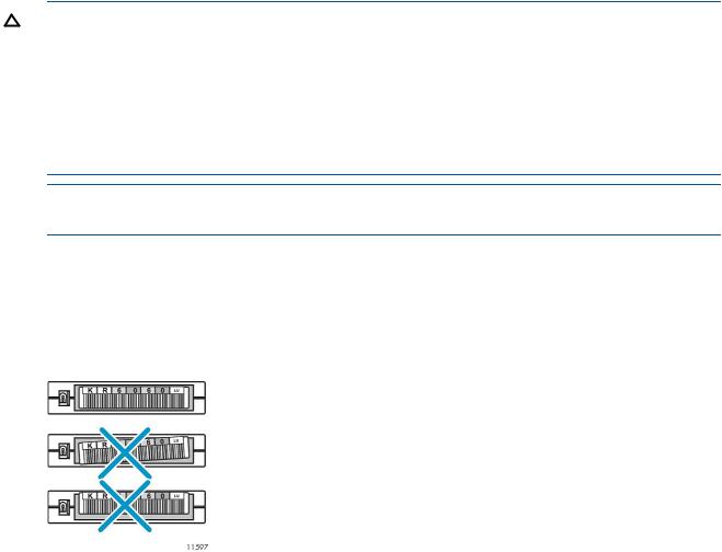
Ultrium tape cartridges have a recessed area located on the face of the tape cartridge next to the write-protect switch. Use this area for attaching the adhesive-backed barcode label. Only apply labels onto the tape cartridge in this designated area. For successful operation of your tape library, place the barcode label entirely within the recessed area, making sure that no part of the label extends outside.
Figure 26 Proper barcode label placement
Position the barcode label as shown in the following figure, with the alphanumeric portion facing the hub side of the tape cartridge (LTO2) or numeric portion away from the hub (LTO3 and later). Never apply multiple labels onto a tape cartridge, because extra labels can cause the tape cartridge to jam inside a tape drive.
Always use the proper barcode labels for your tape drive technology. An L2 (Ultrium 460), L3 (Ultrium 960), L4 (Ultrium 1840), or L5 (Ultrium 3280), L6 (Ultrium 6650) identifier is located at the end of the 8-character Ultrium barcode labels on data cartridges. The universal LTO cleaning cartridges have a CLN and L1 identifier on the label.
30 Using the library
Loading...