


HP 5400R zl2 Switches
Installation and Getting Started Guide
Power over Ethernet

HP 5400R zl2 Switches
Installation and Getting Started Guide

HP 5412R zl2 Switch© Copyright 2005 - 2013, 2015 Hewlett-Packard Development
Company, L.P.
Manual Part Number
5998-7652 May 2015
Applicable Products
HP 5406R zl2 Switch |
J9821A |
|
|
HP 5412R zl2 Switch |
J9822A |
|
|
HP 5412R 92GT PoE+ / 4SFP+ (No PSU) v3 zl2 Switch |
JL001A |
|
|
HP 5406R 8-port 1/2.5/5/10GBASE-T PoE+ / 8-port SFP+ (No PSU) v3 zl2 |
JL002A |
Switch |
|
|
|
HP 5406R 44GT PoE+ / 4SFP+ (No PSU) v3 zl2 Switch |
JL003A |
|
|
HP 5406R 16-port SFP+ (No PSU) v3 zl2 Switch |
JL095A |
|
|
HP 24p 10/100/1000BASE-T PoE+ v3 zl2 Mod |
J9986A |
|
|
HP 24p 10/100/1000BASE-T v3 zl2 Mod |
J9987A |
|
|
HP 24p 1GbE SFP v3 zl2 Mod |
J9988A |
|
|
HP 12p PoE+ / 12p 1GbE SFP v3 zl2 Mod |
J9989A |
|
|
HP 20p PoE+ / 4p SFP+ v3 zl2 Mod |
J9990A |
|
|
HP 20p PoE+ / 4p 1/2.5/5/XGT v3 zl2 Mod |
J9991A |
|
|
HP 20p PoE+ / 1p 40GbE QSFP+ v3 zl2 Mod |
J9992A |
|
|
HP 8p 1G/10GbE SFP+ v3 zl2 Mod |
J9993A |
|
|
8p 1/HP 2.5/5/XGT PoE+ v3 zl2 Mod |
J9995A |
|
|
HP 2p 40GbE QSFP+ v3 zl2 Mod |
J9996A |
|
|
HP 8-port 10GBASE-T v2 zl Module |
J9546A |
|
|
HP 8-port 10GbE SFP+ v2 zl Module |
J9538A |
|
|
HP 20-port Gig-T PoE+ / 2-port 10GbE SFP+ v2 zl Module |
J9536A |
|
|
HP 20-port Gig-T PoE+ / 4-port SFP v2 zl Module |
J9535A |
|
|
HP 24-port SFP v2 zl Module |
J9537A |
|
|
HP 12-port Gig-T PoE+ / 12-port SFP v2 zl Module |
J9637A |
|
|
HP 24-port Gig-T PoE+ v2 zl Module |
J9534A |
|
|
HP 24-port 10/100 PoE+ v2 zl Module |
J9547A |
|
|
HP 24-port Gig-T v2 zl Module |
J9550A |
|
|
HP 20-port Gig-T / 4-port SFP v2 zl Module |
J9549A |
|
|
HP 20-port Gig-T / 2-port 10GbE SFP+ v2 zl Module |
J9548A |
|
|
HP Advanced Services v2 zl Module with HDD |
J9857A |
|
|
HP Advanced Services v2 zl Module with SSD |
J9858A |
|
|
HP 5406R-44G-PoE+/2SFP+ (No PSU) v2 zl2 Switch |
J9823A |
|
|
HP 5406R-44G-PoE+/4SFP (No PSU) v2 zl2 Switch |
J9824A |
|
|
HP 5412R-92G-PoE+/2SFP+ (No PSU) v2 zl2 Switch |
J9825A |
|
|
HP 5412R-92G-PoE+/4SFP (No PSU) v2 zl2 Switch |
J9826A |
|
|
HP 5406R-8XGT/8SFP+ (No PSU) v2 zl2 Switch |
J9868A |
|
|
HP 5400R zl2 Management Module |
J9827A |
|
|
HP 5400R |
700W PoE+ zl2 Power Supply |
J9828A |
|
|
|
HP 5400R |
1100W PoE+ zl2 Power Supply |
J9829A |
|
|
|
HP 5400R |
2750W PoE+ zl2 Power Supply |
J9830A |
|
|
|
HPMSM775zl PremiumControllerModule |
J8940A |
|
|
|
|
HP X450 4U/7U Universal 4-Post Rack Mounting Kit |
J9852A |
|
|
|
|
HP 5406R zl2 Switch Fan Tray |
J9831A |
|
|
|
|
HP 5412R zl2 Switch Fan Tray |
J9832A |
|
|
|
|
Disclaimer
HEWLETT-PACKARD COMPANY MAKES NO WARRANTY OF ANY KIND WITH REGARD TO THIS MATERIAL, INCLUDING, BUT NOT LIMITED TO, THE IMPLIED WARRANTIES OF MERCHANTABILITY AND FITNESS FOR A PARTICULAR PURPOSE. Hewlett-Packard shall not be liable for errors contained herein or for incidental or consequential damages in connection with the furnishing, performance, or use of this material.
The information contained herein is subject to change
without notice.The only warranties for HP products and services are set forth in the express warranty statements accompanying such products and services. Nothing herein should be construed as constituting an additional warranty. HP shall not be liable for technical or editorial errors or omissions contained herein.
Hewlett-Packard assumes no responsibility for the use or reliability of its software on equipment that is not furnished by Hewlett-Packard.
Warranty
For HP warranty information, visit
www.hp.com/networking/support
A copy of the specific warranty terms applicable to your HewlettPackard products and replacement parts can be obtained from your HP Sales and Service Office or authorized dealer.
Safety
Before installing and operating these products, please read the “Installation Precautions” in Chapter 2, and the safety statements in Appendix C.
Hewlett-Packard Company
8000 Foothills Boulevard, m/s 5551 Roseville, California 95747-5551 http://www.hp.com/networking

Contents
1 Introducing the HP 5400R zl2 Switches
Overview of HP 5400R zl2 Switches . . . . . . . . . . . . . . . . . . . . . . . . . . . . . . . . 1-2 HP 5406R zl2 Switches . . . . . . . . . . . . . . . . . . . . . . . . . . . . . . . . . . . . . . . 1-2 HP 5412R zl2 Switches . . . . . . . . . . . . . . . . . . . . . . . . . . . . . . . . . . . . . . . 1-4 HP 5406R zl2 Switch . . . . . . . . . . . . . . . . . . . . . . . . . . . . . . . . . . . . . . . . . 1-5 HP 5412R zl2 Switch . . . . . . . . . . . . . . . . . . . . . . . . . . . . . . . . . . . . . . . . . 1-6
Network Connectivity, Speeds and Technologies . . . . . . . . . . . . . . . . . . . . 1-7
Front of the Switch . . . . . . . . . . . . . . . . . . . . . . . . . . . . . . . . . . . . . . . . . . . . . . 1-8
LEDs . . . . . . . . . . . . . . . . . . . . . . . . . . . . . . . . . . . . . . . . . . . . . . . . . . . . . 1-10
LED Mode Select Button and Indicator LEDs . . . . . . . . . . . . . . . . . . . 1-14
Console Port . . . . . . . . . . . . . . . . . . . . . . . . . . . . . . . . . . . . . . . . . . . . . . 1-15
Out-of-Band Management (OOBM) Port . . . . . . . . . . . . . . . . . . . . . . . 1-16
System Reset Button . . . . . . . . . . . . . . . . . . . . . . . . . . . . . . . . . . . . . . . . 1-16
Clear Button . . . . . . . . . . . . . . . . . . . . . . . . . . . . . . . . . . . . . . . . . . . . . . . 1-16
MM Shutdown Button . . . . . . . . . . . . . . . . . . . . . . . . . . . . . . . . . . . . . . . 1-17
MM Reset Button . . . . . . . . . . . . . . . . . . . . . . . . . . . . . . . . . . . . . . . . . . . 1-17
Back of the Switch . . . . . . . . . . . . . . . . . . . . . . . . . . . . . . . . . . . . . . . . . . . . . 1-19
Power Connector . . . . . . . . . . . . . . . . . . . . . . . . . . . . . . . . . . . . . . . . . . 1-20
Redundant Power Supply . . . . . . . . . . . . . . . . . . . . . . . . . . . . . . . . . . . . 1-20
Switch Accessories . . . . . . . . . . . . . . . . . . . . . . . . . . . . . . . . . . . . . . . . . . . . . 1-22
Switch Features . . . . . . . . . . . . . . . . . . . . . . . . . . . . . . . . . . . . . . . . . . . . . . . 1-24
2 Installing the HP 5400R zl2 Switches
Included Parts . . . . . . . . . . . . . . . . . . . . . . . . . . . . . . . . . . . . . . . . . . . . . . . . . . 2-1
Switch Accessories . . . . . . . . . . . . . . . . . . . . . . . . . . . . . . . . . . . . . . . . . 2-2
Power Cords . . . . . . . . . . . . . . . . . . . . . . . . . . . . . . . . . . . . . . . . . . . . . . . 2-2
Installation Procedures . . . . . . . . . . . . . . . . . . . . . . . . . . . . . . . . . . . . . . . . . . 2-4
Summary . . . . . . . . . . . . . . . . . . . . . . . . . . . . . . . . . . . . . . . . . . . . . . . . . . . 2-4
iii

Installation Precautions . . . . . . . . . . . . . . . . . . . . . . . . . . . . . . . . . . . . . |
. 2-6 |
|
Installation Precautions (continued) . . . . . . . . . . . . . . . . . . . . . . . . . . . |
2-7 |
|
1. |
Prepare the Installation Site . . . . . . . . . . . . . . . . . . . . . . . . . . . . . . . . |
2-8 |
|
Cabling Infrastructure . . . . . . . . . . . . . . . . . . . . . . . . . . . . . . . . . . . . |
2-8 |
|
Installation Location . . . . . . . . . . . . . . . . . . . . . . . . . . . . . . . . . . . . . |
2-8 |
2. |
Install Switch Modules . . . . . . . . . . . . . . . . . . . . . . . . . . . . . . . . . . . . . |
2-8 |
|
Installing a Management Module Battery . . . . . . . . . . . . . . . . . . . |
2-10 |
3. |
(Optional) Install Another Power Supply . . . . . . . . . . . . . . . . . . . . . |
2-12 |
4. |
Verify the Switch Passes Self Test . . . . . . . . . . . . . . . . . . . . . . . . . . |
2-14 |
|
LED Behavior: . . . . . . . . . . . . . . . . . . . . . . . . . . . . . . . . . . . . . . . . . |
2-16 |
5. Mount the Switch . . . . . . . . . . . . . . . . . . . . . . . . . . . . . . . . . . . . . . . . |
2-16 |
|
|
Rack or Cabinet Mounting . . . . . . . . . . . . . . . . . . . . . . . . . . . . . . . |
2-17 |
. |
. . . . . . . . . . . . . . . . . . . . . . . . . . . . . . . . . . . . . . . . . . . . . . . . . . . . . . . . . |
2-18 |
|
Horizontal Surface Mounting . . . . . . . . . . . . . . . . . . . . . . . . . . . . . |
2-20 |
6. |
Install the Grounding Wire . . . . . . . . . . . . . . . . . . . . . . . . . . . . . . . . . |
2-20 |
7. Connect the Switch to a Power Source . . . . . . . . . . . . . . . . . . . . . . |
2-21 |
|
8. Connect the Network Cables . . . . . . . . . . . . . . . . . . . . . . . . . . . . . . . 2-22
10. (Optional) Connect to the Management Console of the Switch . 2-23
Terminal Configuration . . . . . . . . . . . . . . . . . . . . . . . . . . . . . . . . . . |
2-23 |
Setting Up a Console Connection . . . . . . . . . . . . . . . . . . . . . . . . . |
2-24 |
Console Cable Pinouts . . . . . . . . . . . . . . . . . . . . . . . . . . . . . . . . . . |
2-26 |
Telnet Console Access . . . . . . . . . . . . . . . . . . . . . . . . . . . . . . . . . . |
2-26 |
Out-of-Band Management (OOBM) Port . . . . . . . . . . . . . . . . . . . . . . . |
2-27 |
Hot Swapping Switch Modules . . . . . . . . . . . . . . . . . . . . . . . . . . . . . . . . . . . 2-27
Adding or Replacing Modules . . . . . . . . . . . . . . . . . . . . . . . . . . . . . . . . 2-28
3 Getting Started With Switch Configuration
Recommended Minimal Configuration . . . . . . . . . . . . . . . . . . . . . . . . . . 3-1
Using the Switch Setup Screen . . . . . . . . . . . . . . . . . . . . . . . . . . . . . . . . 3-2
Where to Go From Here . . . . . . . . . . . . . . . . . . . . . . . . . . . . . . . . . . . . . . 3-4
Using the IP Address for Remote Switch Management . . . . . . . . . . . . . . . . 3-5
Starting a Telnet Session . . . . . . . . . . . . . . . . . . . . . . . . . . . . . . . . . . . . . 3-5
Starting a Web Browser Session . . . . . . . . . . . . . . . . . . . . . . . . . . . . . . . 3-5
4 Replacing Components
Replacing Power Supplies . . . . . . . . . . . . . . . . . . . . . . . . . . . . . . . . . . . . . . . . 4-2
iv

Replacing Fan Trays . . . . . . . . . . . . . . . . . . . . . . . . . . . . . . . . . . . . . . . . . . . . . 4-4
Replacing the Management Module . . . . . . . . . . . . . . . . . . . . . . . . . . . . . . . . 4-5
Replacing the Management Module SD Card . . . . . . . . . . . . . . . . . . . . . . . . 4-6 Installing an SD Card . . . . . . . . . . . . . . . . . . . . . . . . . . . . . . . . . . . . . . . . 4-6
5 Troubleshooting
Basic Troubleshooting Tips . . . . . . . . . . . . . . . . . . . . . . . . . . . . . . . . . . . . . |
. 5-2 |
Diagnosing with the LEDs . . . . . . . . . . . . . . . . . . . . . . . . . . . . . . . . . . . . . . . |
. 5-4 |
HP networking tools . . . . . . . . . . . . . . . . . . . . . . . . . . . . . . . . . . . . . . . . . . . |
5-10 |
Hardware Diagnostic Tests . . . . . . . . . . . . . . . . . . . . . . . . . . . . . . . . . . . . . . 5-11
Reasons for Resetting the Switch . . . . . . . . . . . . . . . . . . . . . . . . . . . . . 5-11
Methods of Resetting the Switch . . . . . . . . . . . . . . . . . . . . . . . . . . . . . . 5-11
Testing the Switch by Resetting It . . . . . . . . . . . . . . . . . . . . . . . . . . . . 5-11 Checking the Switch LEDs . . . . . . . . . . . . . . . . . . . . . . . . . . . . . . . 5-12 Checking Console Messages . . . . . . . . . . . . . . . . . . . . . . . . . . . . . . 5-12
Testing Twisted-Pair Cabling . . . . . . . . . . . . . . . . . . . . . . . . . . . . . . . . . 5-13
Testing Switch-to-Device Network Communications . . . . . . . . . . . . 5-13
Testing End-to-End Network Communications . . . . . . . . . . . . . . . . . 5-13
Restoring the Factory Default Configuration . . . . . . . . . . . . . . . . . . . . . . . 5-14
Downloading New Software . . . . . . . . . . . . . . . . . . . . . . . . . . . . . . . . . . . . . 5-15
HP Customer Support Services . . . . . . . . . . . . . . . . . . . . . . . . . . . . . . . . . . 5-15
Before Calling Support . . . . . . . . . . . . . . . . . . . . . . . . . . . . . . . . . . . . . . 5-15
A Specifications
Physical . . . . . . . . . . . . . . . . . . . . . . . . . . . . . . . . . . . . . . . . . . . . . . . . . . . A-1
Electrical . . . . . . . . . . . . . . . . . . . . . . . . . . . . . . . . . . . . . . . . . . . . . . . . . A-1
Environmental . . . . . . . . . . . . . . . . . . . . . . . . . . . . . . . . . . . . . . . . . . . . . A-2
Acoustic . . . . . . . . . . . . . . . . . . . . . . . . . . . . . . . . . . . . . . . . . . . . . . . . . . A-2 5406R zl2 Switch and its bundles: . . . . . . . . . . . . . . . . . . . . . . . . . A-2 5412R zl2 Switch and its bundles: . . . . . . . . . . . . . . . . . . . . . . . . . A-2
Safety . . . . . . . . . . . . . . . . . . . . . . . . . . . . . . . . . . . . . . . . . . . . . . . . . . . . A-3
Technology Standards and Safety Compliance . . . . . . . . . . . . . . . . . . A-3
v

B Cabling and Technology Information
Cabling and Technology Information Specifications . . . . . . . . . . . . |
B-1 |
Technology Distance Specifications . . . . . . . . . . . . . . . . . . . . . . . . . . . |
B-3 |
Mode Conditioning Patch Cord . . . . . . . . . . . . . . . . . . . . . . . . . . . . . . . . . . |
B-6 |
Installing the Patch Cord . . . . . . . . . . . . . . . . . . . . . . . . . . . . . . . . . . . . |
B-6 |
Twisted-Pair Cable/Connector Pin-Outs . . . . . . . . . . . . . . . . . . . . . . . . . . . B-8
Straight-Through Twisted-Pair Cable for
10 Mbps or 100 Mbps Network Connections . . . . . . . . . . . . . . . . . . . B-10 Cable Diagram . . . . . . . . . . . . . . . . . . . . . . . . . . . . . . . . . . . . . . . . B-10 Pin Assignments . . . . . . . . . . . . . . . . . . . . . . . . . . . . . . . . . . . . . . . B-10
Crossover Twisted-Pair Cable for
10 Mbps or 100 Mbps Network Connection . . . . . . . . . . . . . . . . . . . . B-12 Cable Diagram . . . . . . . . . . . . . . . . . . . . . . . . . . . . . . . . . . . . . . . . B-12 Pin Assignments . . . . . . . . . . . . . . . . . . . . . . . . . . . . . . . . . . . . . . . B-12
Straight-Through Twisted-Pair Cable for
1000 Mbps Network Connections . . . . . . . . . . . . . . . . . . . . . . . . . . . . B-14 Cable Diagram . . . . . . . . . . . . . . . . . . . . . . . . . . . . . . . . . . . . . . . . B-14 Pin Assignments . . . . . . . . . . . . . . . . . . . . . . . . . . . . . . . . . . . . . . . B-15
C Safety and Regulatory Statements
Safety Information . . . . . . . . . . . . . . . . . . . . . . . . . . . . . . . . . . . . . . . . . . . . . |
C-1 |
Informations concernant la sécurité . . . . . . . . . . . . . . . . . . . . . . . . . . . . . . C-2
Hinweise zur Sicherheit . . . . . . . . . . . . . . . . . . . . . . . . . . . . . . . . . . . . . . . . . C-3
Considerazioni sulla sicurezza . . . . . . . . . . . . . . . . . . . . . . . . . . . . . . . . . . . |
C-4 |
Consideraciones sobre seguridad . . . . . . . . . . . . . . . . . . . . . . . . . . . . . . . . |
C-5 |
Informações de Segurança . . . . . . . . . . . . . . . . . . . . . . . . . . . . . . . . . . . . . . |
C-6 |
Safety Information (Japan) . . . . . . . . . . . . . . . . . . . . . . . . . . . . . . . . . . . . . . C-7
Safety Information (China) . . . . . . . . . . . . . . . . . . . . . . . . . . . . . . . . . . . . . . C-8
EMC Regulatory Statements . . . . . . . . . . . . . . . . . . . . . . . . . . . . . . . . . . . . . C-9
U.S.A. . . . . . . . . . . . . . . . . . . . . . . . . . . . . . . . . . . . . . . . . . . . . . . . . . . . . C-9
Canada . . . . . . . . . . . . . . . . . . . . . . . . . . . . . . . . . . . . . . . . . . . . . . . . . . . |
C-9 |
Australia/New Zealand . . . . . . . . . . . . . . . . . . . . . . . . . . . . . . . . . . . . . . |
C-9 |
Japan . . . . . . . . . . . . . . . . . . . . . . . . . . . . . . . . . . . . . . . . . . . . . . . . . . . . C-10
Korea . . . . . . . . . . . . . . . . . . . . . . . . . . . . . . . . . . . . . . . . . . . . . . . . . . . . C-10
Taiwan . . . . . . . . . . . . . . . . . . . . . . . . . . . . . . . . . . . . . . . . . . . . . . . . . . |
C-10 |
vi

Regulatory Model Identification Number . . . . . . . . . . . . . . . . . . . . . C-10
D Recycle Statements
Waste Electrical and Electronic Equipment (WEEE) Statements . . . . . . D-1
Index
vii
1
Introducing the HP 5400R zl2 Switches
The HP 5400R zl2 switches include the 5406R zl2 switch, 5412R zl2 switch and their bundles. They are multi-port modular switches that provide Layer 3 routing features, and also low latency for high-speed networking.
This chapter describes your 5400R zl2 switches, including:
■Overview of 5400R zl2 switches, page 1-2
■Network Connectivity, Speeds and Technologies, page 1-7
■Front of the Switches, page 1-8
■Back of the Switch, page 1-19
■Switch Accessories, page 1-22
■Switch Features, page 1-24
zl2 5400R HP the Introducing
Switches
1-1

Switches
Introducing the HP 5400R zl2
Introducing the HP 5400R zl2 Switches
Overview of HP 5400R zl2 Switches
Overview of HP 5400R zl2 Switches
HP 5406R zl2 Switches
■The HP 5406R zl2 switch is available as an open 6-slot chassis (J9821A) with Premium Software.
■The HP 5406R-8XGT/8SFP+ (No PSU) v2 zl2 Switch (J9868A) ships with the following:
•One HP 5406R zl2 Switch (J9821A)
•One HP 8-port 10GBASE-T v2 zl Module (J9546A)
•One HP 8-port 10GbE SFP+ v2 zl Module (J9538A)
■The HP 5406R-44G-PoE+/2SFP+ (No PSU) v2 zl2 Switch (J9823A) ships with the following:
•One HP 5406R zl2 Switch (J9821A)
•One HP 20-port Gig-T PoE+ / 2-port 10GbE SFP+ v2 zl Module (J9536A)
•One HP 24-port Gig-T PoE+ v2 zl Module (J9534A)
■The HP 5406R-44G-PoE+/4SFP (No PSU) v2 zl2 Switch (J9824A) ships with the 5406R zl2 6-slot chassis (J9642A) and the following:
•One HP 5406R zl2 Switch (J9821A)
•One HP 20-port Gig-T PoE+ / 4-port SFP v2 zl Module (J9535A)
•One HP 24-port Gig-T PoE+ v2 zl Module (J9534A)
■The HP 5412R-92G-PoE+-4XG v3 zl2 Switch (JL001A) ships with the following:
•One HP 5412R zl2 Switch (J9822A)
•Three HP 24p 10/100/1000BASE-T PoE+ v3 zl2 Mod (J9986A)
•One HP 20p PoE+ / 4p SFP+ v3 zl2 Mod (J9990A)
■The HP 5406R 8p10GT 8pSFP+ v3 zl2 Switch (JL002A) ships with the following:
•One HP 5406R zl2 Switch (J9821A)
•One HP 8p 1/HP 2.5/5/XGT PoE+ v3 zl2 Mod (J9995A)
•One HP 8p 1G/10GbE SFP+ v3 zl2 Mod (J9993A)
1-2

Introducing the HP 5400R zl2 Switches
Overview of HP 5400R zl2 Switches
■The HP 5406R 8p1PoE0GT 8pSFP+ v3 zl2 Switch (JL003A) ships with the following:
•One HP 5406R zl2 Switch (J9821A)
•One HP 24p 10/100/1000BASE-T PoE+ v3 zl2 Mod (J9986A)
•One HP 20p + / 4p SFP+ v3 zl2 Mod (J9990A)
■The HP 5406R 8p10GT 8pSFP+ v3 zl2 Switch (JL095A) ships with the following:
•One HP 5406R zl2 Switch (J9821A)
•Two HP 8p 1G/10GbE SFP+ v3 zl2 Mod (J9993A)
You must order the power supplies separately for these bundles.
zl2 5400R HP the Introducing
Switches
1-3

Switches
Introducing the HP 5400R zl2
Introducing the HP 5400R zl2 Switches
Overview of HP 5400R zl2 Switches
HP 5412R zl2 Switches
■The HP 5412R zl2 switch is available as an open 12-slot chassis (J9822A) with Premium Software.
■The HP 5412R-92G-PoE+/2SFP+ (No PSU) v2 zl2 Switch (J9825A) ships with the 5412R 12 slot chassis with Premium Software and the following:
•One HP 20-port Gig-T PoE+ / 2-port 10GbE SFP+ v2 zl Module (J9536A)
•Three HP 24-port Gig-T PoE+ v2 zl Module (J9534A)
■The HP 5412R-92G-PoE+/4SFP (No PSU) v2 zl2 Switch (J9826A) ships with the 5412R zl2 12-slot chassis with Premium Software and the following:
•One HP 20-port Gig-T PoE+ / 4-port SFP v2 zl Module (J9535A)
•Three HP 24-port Gig-T PoE+ v2 zl Module (J9534A)
See “Switch Accessories” on page 1-22 for a list of the switch modules that can be installed in the HP 5400R zl2 switches.
1-4
Introducing the HP 5400R zl2 Switches
Overview of HP 5400R zl2 Switches
HP 5406R zl2 Switch
The HP 5406R zl2 switch ships with the 5400R zl2 Management Module and open, 6-slot chassis (J9821A). The switch needs at least one power supply to operate. The 5406R zl2 switch bundles are not shown.
Figure 1-1. HP 5406R zl2 Switch (J9821A)
zl2 5400R HP the Introducing
Switches
1-5

Switches
Introducing the HP 5400R zl2
Introducing the HP 5400R zl2 Switches
Overview of HP 5400R zl2 Switches
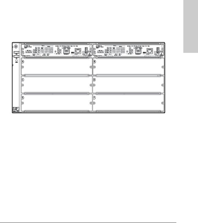
HP 5412R zl2 Switch
The HP 5412R zl2 switch ships with the 5400R zl2 Management Module and open, 12-slot chassis (J9822A). It does not ship with any power supplies. The switch needs at least one power supply to operate. The 5412R zl2 switch bundles are not shown.
Figure 1-2. HP 5412R zl2 Switch (J9822A)
1-6

Introducing the HP 5400R zl2 Switches
Network Connectivity, Speeds and Technologies
Network Connectivity, Speeds and
Technologies
These products support optional network connectivity as follows:
Table 1-1. Optional Network Connectivity, Speeds and Technologies
Transceiver Form-Factor and Connector1
Speed |
Technology |
Cabling |
SFP |
X2 |
SFP+ |
QSFP+ |
|
|
|
|
Connector |
Connector |
Connector |
Connector |
|
|
|
|
|
|
|
|
|
|
100-FX |
Fiber (multimode) |
LC |
|
|
|
|
100 Mbps |
|
|
|
|
|
|
|
100-BX |
Fiber (single |
LC |
|
|
|
|
|
|
|
|
|
|
|||
|
|
mode) |
|
|
|
|
|
|
|
|
|
|
|
|
|
|
1000-T |
Copper (twisted- |
RJ-45 |
|
|
|
|
|
|
pair) |
|
|
|
|
|
|
1000-SX |
Fiber (multimode) |
LC |
|
|
|
|
|
|
|
|
|
|
|
|
|
1000-LX |
Fiber (multimode |
LC |
|
|
|
|
1 Gbps |
|
or single mode) |
|
|
|
|
|
|
1000-LH |
Fiber (single |
LC |
|
|
|
|
|
|
mode) |
|
|
|
|
|
|
1000-BX |
Fiber (single |
LC |
|
|
|
|
|
|
mode) |
|
|
|
|
|
|
10-Gig CX4 |
Copper |
|
CX4 |
|
|
|
|
|
(twinaxial) |
|
|
|
|
|
|
|
|
|
|
|
|
|
|
10-Gig |
Copper |
|
|
Not |
|
|
|
Direct Attach |
(twinaxial) |
|
|
Applicable |
|
|
|
|
|
|
|
|
|
|
10 Gbps |
10-Gig SR |
Fiber (multimode) |
|
SC |
LC |
|
|
|
10-Gig LRM |
Fiber (multimode) |
|
SC |
LC |
|
|
|
|
|
|
|
|
|
|
|
10-Gig LR |
Fiber (single |
|
SC |
LC |
|
|
|
|
mode) |
|
|
|
|
|
|
10-Gig ER |
Fiber (single |
|
SC |
LC |
|
|
|
|
mode) |
|
|
|
|
|
|
40-Gig SR4 |
Fiber (multimode) |
|
|
|
MPO |
|
|
|
|
|
|
|
|
|
40 Gbps |
40-Gig ESR4 |
Fiber (multimode) |
|
|
|
MPO |
|
|
|
|
|
|
|
|
|
|
40-Gig LR4 |
Fiber (single |
|
|
|
LC |
|
|
|
mode) |
|
|
|
|
|
|
|
|
|
|
|
|
|
zl2 5400R HP the Introducing
Switches
1-7

Switches
Introducing the HP 5400R zl2
Introducing the HP 5400R zl2 Switches
Front of the Switch
Table 1-1. Optional Network Connectivity, Speeds and Technologies
1For supported transceivers, visit www.hp.com/networking/support.
–In the first textbox, type J4858 (for 100-Mb and Gigabit information), or J8436 (for 10-Gigabit information).
–Select any of the products that display in the dropdown list.
–Select Product support information. Then click on Manuals and find the Transceiver Support Matrix. For technical details of cabling and technologies see "Cabling and Technology Information" in the appendices.
Front of the Switch
Figure 1-3. Front of 5406R zl2 Switch
Sl No |
Label |
|
|
1Power and Fault LEDs
2Locator LED
3Module Link and Mode LEDs
4MM Status LEDs
1-8

Introducing the HP 5400R zl2 Switches
Front of the Switch
Sl No |
Label |
|
|
5Status LEDs
6Reset and Clear buttons
7Status LEDs for the Fans, Power Supplies, and Switch Modules
8LED Mode Select button and indicator LEDs
9OOBM Port
10Console Port
11Auxiliary Port
12Switch Modules and slots with Link and Mode LEDs for each port located on each module
This illustration shows the 5406R zl2 Switch, but the labeling and descriptions apply to all of the HP 5400R zl2 switches.
For more information on HP Smart Rate port LEDs and 40G ports, see HP Switch v3 zl2 module installation guide.
zl2 5400R HP the Introducing
Switches
1-9

Switches
Introducing the HP 5400R zl2
Introducing the HP 5400R zl2 Switches
Front of the Switch
|
LEDs |
|
|
As described in the next two tables, there are LEDs on the switch chassis and |
|
|
on the switch modules that keep you informed of the status of the switch and |
|
|
the network connections. |
|
|
Table 1-2. Switch Chassis LEDs |
|
|
|
|
LEDs |
State |
Meaning |
|
|
|
Power |
On |
The switch is receiving power. |
(green) |
Off |
The switch is NOT receiving power. |
|
||
|
|
|
Fault |
Off |
The normal state; indicates that there are no fault conditions on the switch. |
(orange) |
Blinking1 |
A fault has occurred on the switch, one of the switch modules, an individual port, a power |
|
||
|
|
supply, or a fan. The Status LED for the module or other device with the fault will flash |
|
|
simultaneously. |
|
On |
On briefly at the beginning of switch self test after the switch is powered on or reset. If |
|
|
on for a prolonged time, the switch has encountered a fatal hardware failure, or has |
|
|
failed its self test. See chapter 4, “Troubleshooting” for more information. |
|
|
|
Locator |
On |
The Locator LED is used to locate a specific chassis in a area full of chassis. The LED |
(blue) |
Blinking |
can be set to be on solid or blink for a specified number of minutes (1-1440). The default |
|
Off |
is 30 minutes. Use the command “chassislocate”. |
|
|
|
Test |
Off |
The normal operational state; the switch is not undergoing self test. |
(green/Orange) |
On |
The switch self test and initialization are in progress after you have power cycled or |
|
||
|
Green |
reset the switch. The switch is not operational until this LED goes off. The Self Test LED |
|
|
also comes on briefly when you “hot swap” a module into the switch and the module is |
|
|
automatically self tested. |
|
Blinking |
A component of the switch has failed its self test. The Status LED for that component, |
|
Orange1 |
for example a switch module, and the switch Fault LED will flash simultaneously. |
DIMM |
On |
DIMM status is known and fault free. |
(green/Orange) |
Off |
DIMM status is unknown. |
|
||
|
Blinking |
If DIMM, Fault, and Self Test LEDs are blinking, DIMM failed self-test. |
|
Orange1 |
If DIMM and Fault LEDs are blinking, an operational fault has occurred. |
|
|
If fast blinking (400ms On and 400ms Off), an operational alert occurred and is |
|
|
unresolved. |
|
|
|
Chas |
On |
Chassis is functioning normally. |
(green)/Orange |
Blinking |
If the Chassis backplane has a fault, or the fan tray has been removed, or if there are |
|
||
|
Orange |
multiple fan failures. |
|
|
|
Flash |
On |
Flash Card status is known and fault free |
(green/Orange) |
Off |
Flash Card status is unknown. |
|
||
|
|
|
|
|
|
1-10
|
|
Introducing the HP 5400R zl2 Switches |
|
|
Front of the Switch |
|
|
|
LEDs |
State |
Meaning |
|
|
|
|
Blinking |
If Flash, Fault, and Self Test LEDs are blinking, Secure digital card failed self-test. |
|
Orange1 |
If Flash and Fault LEDs are blinking, an operational fault has occurred. |
|
|
If fast blinking (400ms On and 400ms Off), an operational alert occurred and is unresolved |
|
|
(for example, the Secure digital is not present). |
|
|
|
Mgmt |
On |
A Management module is present and fault free. |
(green/Orange) |
Off |
The switch is powered off. |
|
Blinking |
There is a fault on the Management module. |
|
Orange1 |
|
PoE |
On |
If any PoE modules are installed. |
(green/Orange) |
Off |
If no PoE modules are installed. |
|
Slow |
Internal PoE fault. |
|
Blinking |
|
|
Orange1 |
|
|
Fast |
External load fault or denied PoE power. |
|
Blinking |
|
|
|
|
|
Orange2 |
|
Temp |
Off |
Switch temperature is normal. |
(green/Orange) |
Blinking |
An over temperature condition has been detected. |
|
||
|
Orange1 |
|
Fan |
On |
The cooling fans are operating normally. |
(green/Orange) |
Blinking |
One or more of the cooling fans have failed. The switch Fault LED will be blinking |
|
||
|
Orange1 |
simultaneously. |
Internal Power |
On |
A power supply is installed in the position in the back of the switch corresponding to the |
(green/Orange - |
|
number, and the supply is plugged in to an active AC power source. |
numbers |
Off |
A power supply is not installed in the position corresponding to the number. |
corresponding to |
||
the power supply |
Blinking |
The power supply installed in the position corresponding to the number is not plugged |
positions) |
Orange1 |
in to an active AC power source, or has experienced a fault. The switch Fault LED will |
|
|
be blinking simultaneously. |
|
|
|
System Reset |
Single |
Full chassis system is reset, without failover. |
Button |
press (0.2 - |
|
|
5 seconds) |
|
|
|
|
MM Shutdown/ |
Single |
Management Module shuts down. If a standby management module is present, failover |
Reset Button |
press (0.2 - |
occurs. If there is no standby management module, the system reset occurs. |
|
5 seconds) |
|
|
|
|
zl2 5400R HP the Introducing
Switches
1-11

Switches
Introducing the HP 5400R zl2
Introducing the HP 5400R zl2 Switches
Front of the Switch
LEDs |
State |
Meaning |
|
|
|
|
|
Modules (green - |
On |
A module is installed in the switch module slot corresponding to the letter and the module |
|
letters |
|
is undergoing or has passed self test. This also occurs when you install a module when |
|
corresponding to |
|
the switch is already powered on (“hot swap”). |
|
the switch module |
Off |
A module is not installed in the switch module slot corresponding to the letter. |
|
slots) |
|||
Blinking1 |
|
||
|
The module status LED flashes very briefly when a module is being hot swapped. If the |
||
|
|
LED flashes for a prolonged time, the module in the slot corresponding to the letter has |
|
|
|
failed self test or encountered some other fault condition. See chapter 4, |
|
|
|
“Troubleshooting” for a more information. |
|
In PoE Mode: |
On |
PoE is ok for this slot. |
|
|
Blinking1 |
PoE internal fault for this slot. |
|
|
Blinking2 |
PoE load fault or insufficient power for this slot. |
|
|
Off |
The module in this slot is not a PoE module. |
|
|
|
|
|
LED Mode Select |
Act |
Indicates that the port Mode LEDs are displaying network activity information. |
|
(5 green LEDs) |
FDx |
Indicates that the port Mode LEDs are lit for ports that are in Full Duplex Mode. |
|
|
|||
|
PoE |
Indicates which ports are supplying PoE power. |
|
|
|
• If the Mode LED is on the port is providing PoE power. |
|
|
|
• If the Mode LED is off the port is not providing PoE power. |
|
|
|
• If the Link LED is on the port is enabled for PoE. |
|
|
|
• If the Link LED is off the port is disabled for PoE. |
|
|
|
• If the Link LED is blinking Orange, the port has an error or the port is denied power |
|
|
|
due to insufficient power. |
|
|
Spd |
Indicates the Port LEDs are displaying the connection speed at which each port is |
|
|
|
operating: |
|
|
|
• if the Port LED is off, the port is operating at 10 Mbps or at 100 Mbps |
|
|
|
• if the Port LED is blinking, the port is operating at 1 Gbps |
|
|
|
• if the Port LED is on continuously, the port is operating at 10 Gbps |
|
|
Usr |
Reserved for future development |
|
|
|
|
|
Auxiliary (green/ |
Blinking |
Indicates the switch is processing a USB command file. |
|
orange) For more |
green1 |
|
|
information see |
On green |
The switch has successfully finished processing the USB command file. |
|
the Management |
|||
and Configuration |
Blinking |
Indicates an error condition. |
|
Guide for your |
|||
Orange2 |
|
||
switch. |
|
||
|
|
||
|
Off |
Indicates that no USB device has been inserted, or that the inserted USB device cannot |
|
|
|
be recognized, or that no command file can be found on the inserted USB device. |
|
|
|
|
1-12

|
|
Introducing the HP 5400R zl2 Switches |
|
|
Front of the Switch |
|
|
|
LEDs |
State |
Meaning |
|
|
|
MM State |
Active |
Indicates that this is the Active management module when one or two management |
|
|
modules are installed in the switch. |
|
Standby |
Indicates that this is the Standby management module when two management modules |
|
|
are installed in the switch. |
|
|
Indicates that this management Module has been shut down via the Module Shutdown |
|
Down |
switch or via a CLI command. |
|
|
|
1 The blinking behavior is an on/off cycle once every 1.6 seconds, approximately. |
||
2 The blinking behavior is an on/off cycle once every 0.5 seconds, approximately. |
||
Table 1-3. Switch Module LEDs
These LEDs are located on the modules themselves, one pair for each port.
LED |
State |
Meaning |
|
|
|
Link |
On |
Indicates the port is enabled and receiving a link beat signal (for the twisted-pair |
|
|
ports), or a strong enough light level (for the fiber-optic ports) from the connected |
|
|
device. |
|
Off |
One of these conditions exists: |
|
|
• no active network cable is connected to the port |
|
|
• the port is not receiving link beat or sufficient light |
|
|
• the port has been disabled through the switch console, the web browser |
|
|
interface, Intelligent Management Center, or other network management tool. |
|
Blinking |
The port has failed self test. The switch Fault, Self Test LEDs, and appropriate |
|
Orange1 |
module status LEDs will flash simultaneously. |
Mode |
Depending on the mode selected, displays the following: network activity information, whether |
|
|
the port is configured for Full Duplex operation, maximum speed operation, or whether PoE |
|
|
power is being supplied or not. See “LED Mode Select Button and Indicator LEDs” below for |
|
|
more information. |
|
|
|
|
1 The blinking behavior is an on/off cycle once every 1.6 seconds, approximately.
For more information on HP Smart Rate port LEDs and 40G ports, see HP
Switch v3 zl2 module installation guide.
zl2 5400R HP the Introducing
Switches
1-13
Switches
Introducing the HP 5400R zl2
Introducing the HP 5400R zl2 Switches
Front of the Switch
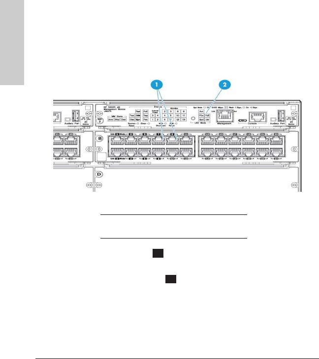
LED Mode Select Button and Indicator LEDs
To optimize the amount of information that can be displayed for each of the switch ports, the 5400R zl2 switches use a Mode LED for each port. The operation of this LED is controlled by the LED Mode Select button on the switch chassis, and the current selection is indicated by the mode indicator LEDs near the button. Press the button to change from one mode to the next.
Figure 1-4. Mode LEDs and LED Mode Select Button
1Mode LEDs (one for each port)
2LED Mode Select button and indicator LEDs
■If the Activity Act indicator LED is lit, each port Mode LED displays activity information for the port—it flickers faster for the higher traffic rates.
■If the Full Duplex FDx indicator LED is lit, the port Mode LEDs light for those ports that are operating in full duplex.
■If the speed indicator LED is lit, the port LEDs behave as follows to indicate the connection speed for the port:
•Off = 10 Mbps or 100 Mbps
•Blinking = 1 Gbps (the blinking behavior is a repeated on/off cycle once every 0.5 sec.)
•On = Faster than 1 Gbps
1-14

Introducing the HP 5400R zl2 Switches
Front of the Switch
For 10/100/1000BASE-T, SFP and SFP+ Ports:
•Off = 10 Mbps or 100 Mbps
•Flashing = 1 Gbps
•On = >1Gbps
For HP Smart Rate ports:
•Off = Not linked
•Slow Flash = 1 Gbps
•Double Flash = 2.5 Gbps
•Triple Flash = 5 Gbps
•On = 10 Gbps
For QSFP+ ports:
•Off = Not linked
•Fast Flash = 40 Gbps
For more information on HP Smart Rate port LEDs and 40G ports in speed mode, see HP Switch v3 zl2 module installation guide.
■If the PoE PoE indicator LED is lit, the Link and Mode LEDs indicate PoE status:
Link LED:
•On = PoE is enabled on this port
•Off = PoE is disabled on this port.
•Slow Blinking Orange = Internal PoE fault on this port.
•Fast Blinking Orange = This port is denied PoE power or has an external load fault.
Mode LED:
•On = PoE power is be supplied on this port
•Off = PoE is not being supplied on this port.
Console Port
There are two console ports on the switch. These ports are used to connect a console to the switch. The one port uses the serial cable supplied with the switch and the other port uses a MicroUSB cable which is not supplied with the switch. This connection is described under “Connecting a Console to the Switch” in chapter 2, “Installing the 5400R zl2 Switches”. The console is a fullfeatured interface that can be used to configure, monitor, and troubleshoot the switch. It can be run on a PC, laptop, or handheld device emulating a VT100 terminal, or on a standard VT-100 terminal.
zl2 5400R HP the Introducing
Switches
1-15

Switches
Introducing the HP 5400R zl2
Introducing the HP 5400R zl2 Switches
Front of the Switch
Out-of-Band Management (OOBM) Port
This RJ-45 port is used to connect a dedicated management network to the switch.
To use: connect an RJ-45 network cable to the Management port to manage an HP 5400R zl2 Switch through Telnet from a remote PC or a UNIX workstation.
To use this port, the switch must have an IP address. IP settings can be configured through a Console port connection or automatically from a DHCP/ Bootp server.
A networked out-of-band connection through the Management port allows you to manage data network switches from a physically and logically separate management network.
For more information, see the "Network Out-of-Band Management (OOBM)" appendix in the Management and Configuration Guide at: www.hp.com/ networking/support.
System Reset Button
This button will reset the entire switch, including the second management module, when powered on. This action clears any temporary error conditions that may have occurred, executes the switch self test, and resets all network activity counters to zero. The counters are displayed in the switch console interface, the switch web browser interface, and through SNMP network management applications, such as Intelligent Management Center.
Press the Reset button also after changing the module type that is installed in any of the switch module slots while the switch is powered on. See “Hot Swapping Switch Modules” on page 2-27.
You can also use the no module <slot> command to erase the old module type configuration.
Clear Button
This button is used for the following purposes:
■Deleting Passwords - When pressed for at least one second on either one of the Management Modules, the Clear button deletes any switch console access passwords that you may have configured. Use this feature if you have misplaced the password and need console access.
1-16

Introducing the HP 5400R zl2 Switches
Front of the Switch
This button is provided for your convenience, but its presence means that if you are concerned with the security of the switch configuration and operation, you should make sure the switch is installed in a secure location, such as a locked wiring closet.
■Restoring Factory Default Configuration - When pressed with the Reset button in a specific pattern, the Clear button clears any configuration changes you may have made through the switch console, the web browser interface, or SNMP management, and restores the factory default configuration to the switch. The specific patterns to accomplish the Restore Factory Default Configuration are:
i.Press both the System Reset and Clear buttons simultaneously.
ii.Release the System Reset button, but continue to hold the Clear button.
iii.Release the Clear button immediately when you see the Test LED begins to flash on both the Management Modules.
For the specific method to restore the factory default configuration, see “Restoring the Factory Default Configuration” in chapter 4, “Troubleshooting” of this manual.
MM Shutdown Button
When you want to remove a module, the MM shutdown button halts all the management functions. It will not reboot when this button is pressed.
If the system is running with two management modules and the MM shutdown button is pressed on the active module, this causes a failover to the standby module.
If the system is running with two management modules and the MM shutdown button is pressed on the standby module, no failover occurs.
MM Reset Button
The MM reset button resets the Management Module to which it is attached.
If the system is running with two management modules, and if the active module is reset, this causes a failover to the standby module.
If the system is running with two management modules and the on reset is the active, no failover occurs.
When a user presses the reset button, the module will be reset and will reboot.
zl2 5400R HP the Introducing
Switches
1-17

Switches
Introducing the HP 5400R zl2
Introducing the HP 5400R zl2 Switches
Front of the Switch
If the system is running with two management modules and the MM shutdown button is pressed on the standby module, no failover occurs.
1-18

Introducing the HP 5400R zl2 Switches
Back of the Switch
Back of the Switch
Figure 1-5. Back of a 5406R zl2 switch with one power supply
1Ground lug mounting holes
2AC power connector
3Power and Fault LEDs
4Slot for installing optional redundant power supply
zl2 5400R HP the Introducing
Switches
Figure 1-6. Back of a 5412R zl2 switch with two power supplies
1-19

Switches
Introducing the HP 5400R zl2
Introducing the HP 5400R zl2 Switches
Back of the Switch
Power Connector
The Series 5400R zl2 Switches do not have a power switch; they are powered on when connected to an active AC power source.
The 5400R zl2 switches automatically adjust to any voltage between 100-127 volts or 200-240 volts when using the J9828A power supply, 110-127 volts or 200-240 volts when using the J9829A power supply, and 115-127 volts and 200240 volts when using the J9830A power supply, and either 50 or 60 Hz. There are no voltage range settings required.
|
Redundant Power Supply |
|
Load-sharing redundant power supplies J9828A, max 630W, system power |
|
(12V), 275W of POE power; J9829A, 630W max system (12V) power, 900W max |
|
POE power; J9830A, 630W max, system (12V) power, 2500W max POE power |
|
can be installed in the back of the 5400R zl2 switches. To provide redundancy, |
|
each power supply should be connected to different AC power sources. Then, |
|
if one AC power source fails, the switch will continue to run. |
|
|
N o t e |
Any combination of J9828A, J9829A and J9830A power supplies can be used |
|
in the same switch. However, HP recommends to only use like supplies in a |
|
unit for more deterministic behavior in event of a power supply failure. |
|
|
|
|
C a u t i o n |
The switch redundant power supply is hot swappable, but, as indicated by the |
|
caution statement on the power supply, it must be disconnected from AC |
|
power before being installed or removed. |
|
CAUTION: |
|
.Refer to the installation guide for proper power cord selection |
|
.Disconnect AC power from the power supply BEFORE installing or |
|
removing the supply. Otherwise, damage to the. equipment may result. |
|
Because the switch can run on a single supply, removing a redundant supply |
|
|
|
will not interrupt switch operation. However, with a single power supply |
|
system will power on Interface module up to 630W. The rest of the Interface |
|
modules are powered on the priority of the slot. The slot A has the highest |
|
priority and the slot L has the lowest priority. |
|
When power is restored from a second (or more) power supplies, a system |
|
reload or interface module reset is not required to restore operation to slots |
|
G-L. The 5400R modules will restart by themselves when power recovers. |
1-20
 Loading...