


 Loading...
HP 6125G & 6125G/XG Blade Switches
Installation Guide
Part number: 5998-3151a
Document version: 6W101-20150605
Legal and notice information
© Copyright 2015 Hewlett-Packard Development Company, L.P.
No part of this documentation may be reproduced or transmitted in any form or by any means without prior written consent of Hewlett-Packard Development Company, L.P.
The information contained herein is subject to change without notice.
HEWLETT-PACKARD COMPANY MAKES NO WARRANTY OF ANY KIND WITH REGARD TO THIS MATERIAL, INCLUDING, BUT NOT LIMITED TO, THE IMPLIED WARRANTIES OF MERCHANTABILITY AND FITNESS FOR A PARTICULAR PURPOSE. Hewlett-Packard shall not be liable for errors contained herein or for incidental or consequential damages in connection with the furnishing, performance, or use of this material.
The only warranties for HP products and services are set forth in the express warranty statements accompanying such products and services. Nothing herein should be construed as constituting an additional warranty. HP shall not be liable for technical or editorial errors or omissions contained herein.

Contents
Product overview·························································································································································· 1
Panel views ········································································································································································1
Installing the blade switch ··········································································································································· 3
Preparing for installation ··················································································································································3 Installing and removing the blade switch·······················································································································3 Installing the blade switch ·······································································································································3 Removing the blade switch······································································································································5 Connecting the blade switch to the network ··················································································································5 Connecting the blade switch to the network through twisted pair cables··························································5 Connecting the blade switch to the network through optical fibers····································································5 Testing connectivity ···························································································································································6
Accessing the blade switch for the first time ·············································································································· 7
Logging in through the console port ·······························································································································7 Setting up the configuration environment ··············································································································7 Setting terminal parameters·····································································································································8 Logging in through the OA module ····························································································································· 11 Configuring the blade switch········································································································································ 11 Configuring an authentication method ··············································································································· 11 Configuring the basic network settings ··············································································································· 12 Configuration example ········································································································································· 12
Setting up an IRF fabric ·············································································································································14
Planning IRF fabric setup··············································································································································· 14 Determining the number of IRF member devices································································································ 14 Identifying the master switch and planning IRF member IDs ············································································ 14 Planning IRF topology and connections·············································································································· 14 Identifying physical IRF ports on the member switches ····················································································· 15 Planning the cabling scheme ······························································································································· 16
Configuring basic IRF settings······································································································································· 16 Connecting the physical IRF ports ································································································································ 16 Accessing the IRF fabric to verify the configuration ··································································································· 16
Troubleshooting··························································································································································18
Troubleshooting methods··············································································································································· 18 Collecting log and operating information ··················································································································· 18 Software failures ···························································································································································· 19 No terminal display ·············································································································································· 19 Garbled terminal display······································································································································ 20 Configuration problems ········································································································································ 20 Software upgrade failure······································································································································ 20 Failures during operation ·············································································································································· 21 IRF member device failure············································································································································· 21 Password loss ································································································································································· 22 Login password loss ·············································································································································· 22 BootWare password loss ····································································································································· 22 Super password loss ············································································································································· 22 Hardware failures ·························································································································································· 23 Interface failure······························································································································································· 23
i
Support and other resources ·····································································································································25
Contacting HP ································································································································································ 25 Subscription service ·············································································································································· 25 Related information························································································································································ 25 Documents······························································································································································ 25 Websites································································································································································· 25 Conventions ···································································································································································· 26
Appendix A Technical specifications························································································································28
Appendix B Ports and LEDs ·······································································································································29
Ports ················································································································································································· 29 Console port ·························································································································································· 29 10/100/1000Base-T Ethernet port ···················································································································· 29 IRF/SFP port and SFP port···································································································································· 29 SFP+ port································································································································································ 30
LEDs ················································································································································································· 32 Unit ID LED ····························································································································································· 32 Health LED······························································································································································ 32 10/100/1000Base-T Ethernet port LED············································································································· 32 SFP port LED··························································································································································· 33 SFP+ port LED ························································································································································ 33 IRF/SFP port LED···················································································································································· 33
Index ···········································································································································································34
ii
Product overview
The HP 6125 Blade Switch Series includes the models in Table 1:
Table 1 Models in the HP 6125 Blade Switch Series
|
HP description |
RMN |
|
HP 6125G |
HSTNS-BC57-N |
|
|
|
|
HP 6125G/XG |
HSTNS-BC58-N |
|
|
|
|
|
|
IMPORTANT:
For regulatory identification purposes, the HP 6125 Blade Switch Series are assigned Regulatory Model Numbers (RMN). These regulatory numbers should not be confused with the marketing name HP 6125.
Panel views
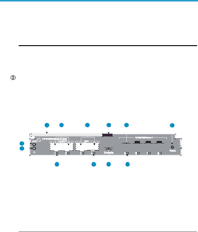
Figure 1 Front panel of the HP 6125G
|
|
|
|
|
|
|
|
|
|
|
|
|
|
|
|
|
|
|
|
|
|
|
|
|
|
|
|
|
|
|
|
|
|
|
|
|
|
|
|
|
|
|
|
|
|
|
|
|
|
|
|
|
|
|
|
|
|
|
|
|
|
|
|
|
|
|
|
|
|
|
|
|
|
|
|
|
|
|
|
|
|
|
|
|
|
|
|
|
|
|
|
|
|
|
|
|
|
|
|
|
|
|
|
|
|
|
|
|
|
|
|
|
|
|
|
|
|
|
|
|
|
|
|
|
|
|
|
|
|
|
|
|
|
|
|
|
|
|
|
|
|
|
|
|
|
|
|
|
|
|
|
|
|
|
|
|
|
|
|
|
|
|
|
|
|
|
|
|
|
|
|
|
|
|
|
|
|
|
|
|
|
|
|
|
|
|
|
|
|
|
|
|
|
|
|
|
|
|
|
|
|
|
|
|
|
|
|
|
|
|
|
|
|
|
|
|
|
|
|
|
|
|
|
|
|
|
|
|
|
|
|
|
|
|
|
|
|
|
|
|
|
|
|
|
|
|
|
|
|
|
|
|
|
|
|
|
|
|
|
|
|
|
|
|
|
|
|
|
|
|
|
|
|
|
|
|
|
|
|
|
|
|
|
|
|
|
|
|
|
|
|
|
|
|
|
|
|
|
|
|
|
|
|
|
|
|
|
|
|
|
|
|
|
|
|
|
|
|
|
|
|
|
|
|
|
|
|
|
|
|
|
|
|
|
|
|
|
|
|
|
|
|
|
|
|
|
|
|
|
|
|
|
|
|
|
|
|
|
|
|
|
|
|
|
|
|
|
|
|
|
|
|
|
|
|
|
|
|
|
|
|
|
|
|
|
|
|
|
|
|
|
|
|
|
|
|
|
|
|
|
|
|
|
|
|
|
|
|
|
|
|
|
|
|
|
|
|
|
|
|
|
|
|
|
|
|
|
|
|
|
|
|
|
|
|
|
|
|
|
|
|
|
|
|
|
|
|
|
|
|
|
|
|
|
|
|
|
|
|
|
|
|
|
|
|
|
|
|
|
|
|
|
|
|
|
|
|
|
|
|
|
|
|
|
|
|
|
|
|
|
|
|
|
|
|
|
|
|
|
|
|
|
|
|
|
|
|
|
|
|
|
|
|
|
|
|
|
|
|
|
|
|
|
|
|
|
|
|
|
|
|
|
|
|
|
|
|
|
|
|
|
|
|
|
|
|
|
|
|
|
|
|
|
|
|
|
|
|
|
|
|
|
|
|
|
|
|
|
|
|
|
|
|
|
|
|
|
|
|
|
|
|
|
|
|
|
|
|
|
|
|
|
|
|
|
|
|
|
|
|
|
|
|
|
|
|
|
|
|
|
|
|
|
|
|
|
|
|
|
|
|
|
|
|
|
|
|
|
|
|
|
|
|
|
|
|
|
|
|
|
|
|
|
|
|
|
|
|
|
|
|
|
|
|
|
|
|
|
|
|
|
|
|
|
|
|
|
|
|
|
|
|
|
|
|
|
|
|
|
|
|
|
|
|
|
|
|
|
|
|
|
|
|
|
|
|
|
|
|
|
|
|
|
|
|
|
|
|
|
|
|
|
|
|
|
|
|
|
|
|
|
|
|
|
|
|
|
|
|
|
|
|
|
|
|
|
|
|
|
|
|
|
|
|
|
|
|
|
|
|
|
|
|
|
|
|
|
|
|
|
|
|
|
|
|
|
|
|
|
|
|
|
|
|
|
|
|
|
|
|
|
|
|
|
|
|
|
|
|
|
|
|
|
|
|
|
|
|
|
|
|
|
|
|
|
|
|
|
|
(1) |
Health LED |
(2) |
Unit ID (UID) LED |
||||||||||||||||||||||||||||||||||||||||||||||||||
(3) |
Ejector lever |
(4) |
IRF/SFP port |
||||||||||||||||||||||||||||||||||||||||||||||||||
(5) |
SFP port |
(6) |
Release tab |
||||||||||||||||||||||||||||||||||||||||||||||||||
(7) |
10/100/1000Base-T auto-sensing Ethernet port |
(8) |
Reset button |
||||||||||||||||||||||||||||||||||||||||||||||||||
(9) |
10/100/1000Base-T auto-sensing Ethernet port LED |
(10) |
Console port |
||||||||||||||||||||||||||||||||||||||||||||||||||
|
|
(11) SFP port LED |
(12) |
IRF/SFP port LED |
|||||||||||||||||||||||||||||||||||||||||||||||||
|
|
|
|
|
|
|
|
|
|
|
|
|
|
|
|
|
|
|
|
|
|
|
|
|
|
|
|
|
|
|
|
|
|
|
|
|
|
|
|
|
|
|
|
|
|
|
|
|
|
|
|
|
|
NOTE:
The Reset button is recessed in the device. To push the Reset button, use a thin, elongated object, such as a pencil.
1
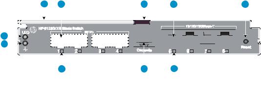
Figure 2 Front panel of the HP 6125G/XG
|
|
|
|
|
|
|
|
|
|
|
|
|
|
|
|
|
|
|
|
|
|
|
|
|
|
|
|
|
|
|
|
|
|
|
|
|
|
|
|
|
|
|
|
|
|
|
|
|
|
|
|
|
|
|
|
|
|
|
|
|
|
|
|
|
|
|
|
|
|
|
|
|
|
|
|
|
|
|
|
|
|
|
|
|
|
|
|
|
|
|
|
|
|
|
|
|
|
|
|
|
|
|
|
|
|
|
|
|
|
|
|
|
|
|
|
|
|
|
|
|
|
|
|
|
|
|
|
|
|
|
|
|
|
|
|
|
|
|
|
|
|
|
|
|
|
|
|
|
|
|
|
|
|
|
|
|
|
|
|
|
|
|
|
|
|
|
|
|
|
|
|
|
|
|
|
|
|
|
|
|
|
|
|
|
|
|
|
|
|
|
|
|
|
|
|
|
|
|
|
|
|
|
|
|
|
|
|
|
|
|
|
|
|
|
|
|
|
|
|
|
|
|
|
|
|
|
|
|
|
|
|
|
|
|
|
|
|
|
|
|
|
|
|
|
|
|
|
|
|
|
|
|
|
|
|
|
|
|
|
|
|
|
|
|
|
|
|
|
|
|
|
|
|
|
|
|
|
|
|
|
|
|
|
|
|
|
|
|
|
|
|
|
|
|
|
|
|
|
|
|
|
|
|
|
|
|
|
|
|
|
|
|
|
|
|
|
|
|
|
|
|
|
|
|
|
|
|
|
|
|
|
|
|
|
|
|
|
|
|
|
|
|
|
|
|
|
|
|
|
|
|
|
|
|
|
|
|
|
|
|
|
|
|
|
|
|
|
|
|
|
|
|
|
|
|
|
|
|
|
|
|
|
|
|
|
|
|
|
|
|
|
|
|
|
|
|
|
|
|
|
|
|
|
|
|
|
|
|
|
|
|
|
|
|
|
|
|
|
|
|
|
|
|
|
|
|
|
|
|
|
|
|
|
|
|
|
|
|
|
|
|
|
|
|
|
|
|
|
|
|
|
|
|
|
|
|
|
|
|
|
|
|
|
|
|
|
|
|
|
|
|
|
|
|
|
|
|
|
|
|
|
|
|
|
|
|
|
|
|
|
|
|
|
|
|
|
|
|
|
|
|
|
|
|
|
|
|
|
|
|
|
|
|
|
|
|
|
|
|
|
|
|
|
|
|
|
|
|
|
|
|
|
|
|
|
|
|
|
|
|
|
|
|
|
|
|
|
|
|
|
|
|
|
|
|
|
|
|
|
|
|
|
|
|
|
|
|
|
|
|
|
|
|
|
|
|
|
|
|
|
|
|
|
|
|
|
|
|
|
|
|
|
|
|
|
|
|
|
|
|
|
|
|
|
|
|
|
|
|
|
|
|
|
|
|
|
|
|
|
|
|
|
|
|
|
|
|
|
|
|
|
|
|
|
|
|
|
|
|
|
|
|
|
|
|
|
|
|
|
|
|
|
|
|
|
|
|
|
|
|
|
|
|
|
|
|
|
|
|
|
|
|
|
|
|
|
|
|
|
|
|
|
|
|
|
|
|
|
|
|
|
|
|
|
|
|
|
|
|
|
|
|
|
|
|
|
|
|
|
|
|
|
|
|
|
|
|
|
|
|
|
|
|
|
|
|
|
|
|
|
|
|
|
|
|
|
|
|
|
|
|
|
|
|
|
|
|
|
|
|
|
|
|
|
|
|
|
|
|
|
|
|
|
|
|
|
|
|
|
|
|
|
|
|
|
|
|
|
|
|
|
|
|
|
|
|
|
|
|
|
|
|
|
|
|
|
|
|
|
|
|
|
|
|
|
|
|
|
|
|
|
|
|
|
|
(1) |
Health LED |
(2) |
Unit ID (UID) LED |
|||||||||||||||||||||||||||||||||||||||||||||||
(3) |
Ejector lever |
(4) |
SFP+ port |
|||||||||||||||||||||||||||||||||||||||||||||||
(5) |
Release tab |
(6) |
10/100/1000Base-T auto-sensing Ethernet port |
|||||||||||||||||||||||||||||||||||||||||||||||
(7) |
Reset button |
(8) |
10/100/1000Base-T auto-sensing Ethernet port LED |
|||||||||||||||||||||||||||||||||||||||||||||||
(9) |
Console port |
|
|
|
|
|
|
|
|
|
|
|
|
|
|
|
(10) SFP+ port LED |
|||||||||||||||||||||||||||||||||
2

Installing the blade switch
The HP 6125 switches can be installed into the HP BladeSystem c3000 and c7000 enclosures. The installation position in the enclosure in this document is only for illustration. For more information, see HP BladeSystem Enclosure Setup and Installation Guide .
Preparing for installation
WARNING!
The blade switches are Class 1 laser devices. Do not stare into any fiber port when the blade switch has power. The laser light emitted from the optical fiber may hurt your eyes.
CAUTION:
Take ESD-preventive measures to avoid damaging the components. For more information, see HP BladeSystem Enclosure Setup and Installation Guide .
•To avoid any equipment damage or bodily injury caused by improper use, follow the enclosure safety recommendations. For more information, see HP BladeSystem Enclosure Setup and Installation Guide.
•Identify the interconnect bay to install the blade switch. For more information, see HP BladeSystem Enclosure Setup and Installation Guide.
Installing and removing the blade switch
IMPORTANT:
•If the blade switch does not install easily, make sure that it is correctly oriented.
•To prevent dust from entering the system, install the interconnect blank into the interconnect bay after removing the blade switch.
Installing the blade switch
1.Wear an ESD-preventive wrist strap and make sure it makes good skin contact and is well grounded.
2.Remove the interconnect blank from the slot.
Keep the removed interconnect blank for future use.
3.Unpack the blade switch.
4.Press the release tab (see callout 1 in Figure 3) and then pull the ejector lever to the open position (see callout 2 in Figure 3).
3

Figure 3 Opening the ejector lever
2 |
1 |
5.Slide the blade switch into the interconnect bay (see callout 1 in Figure 4) until it touches the backplane.
6.Push the ejector lever to the closed position. (See callout 2 in Figure 4).
Figure 4 Sliding the blade switch into the interconnect bay
7.Verify that the Health LED is green after the blade switch starts up. Otherwise, check the installation.
8.Choose proper cables for the blade switch.
For more information about ports, see "Ports." For more information about cable installation, see "Connecting the blade switch to the network."
4

Removing the blade switch
1.Wear an ESD-preventive wrist strap and make sure it makes good skin contact and is well grounded.
2.Press the release tab to open the ejector lever.
3.Pull the ejector lever outwards slowly to take out the blade switch.
Connecting the blade switch to the network
Connecting the blade switch to the network through twisted pair cables
You can use category-5 or above twisted pair cables to connect the 10/100/1000Base-T ports on your blade switch to the network. These ports use RJ-45 connectors and support MDI/MDI-X auto-sensing.
To connect a 10/100/1000Base-T port to a peer device:
1.Plug one end of a twisted pair cable into the RJ-45 port of the blade switch.
2.Plug the other end of the twisted pair cable into the RJ-45 port of the peer device.
3.Verify the port LED for correct connection. For LED status, see "LEDs."
Connecting the blade switch to the network through optical fibers
WARNING!
To avoid injury to your eyes, do not stare at the optical interfaces and optical fiber connectors when connecting optical fibers.
You can install a transceiver module in a fiber port on the blade switch and then plug the fiber connector to the transceiver module. For more information about installing the transceiver module, see Pluggable SFP[SFP+][XFP] Transceiver Modules Installation Guide.
To install a transceiver module into the port on the blade switch and the peer device:
1.Remove the dust cover of the fiber connector, and clean the end of the fiber connector.
2.Remove the dust plug of the transceiver module, plug one end of the optical fiber into the transceiver module, and plug the other end into the transceiver module in the peer device, as shown in Figure 5.
The transmit port on one end must connect to the receive port on the other end.
3.Verify the port LEDs for correct connection.
For more information about LED status, see "LEDs."
5
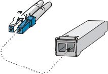
Figure 5 Using LC optical fiber connectors to connect transceiver modules


 LC plug
SFP module
Testing connectivity
After you connect the blade switch to the network, use the ping or tracert command to test network connectivity. For more information about these two commands, see HP 6125 Blade Switch Series Network Management and Monitoring Command Reference.
6
Accessing the blade switch for the first time
Logging in through the console port
The first time you access the blade switch you must use a console cable (see Figure 6) to connect a console terminal, for example, a PC, to the console port on the blade switch.
A console cable is an 8-core shielded cable, with a crimped RJ-45 connector at one end for connecting to the console port of the blade switch, and a DB-9 female connector at the other end for connecting to the serial port on the console terminal.
Figure 6 Console cable
Setting up the configuration environment
To connect a terminal, for example, a PC, to the blade switch:
1.Plug the DB-9 female connector of the console cable to the serial port of the PC.
2.Plug the RJ-45 connector of the console cable to the console port of the blade switch.
IMPORTANT:
Identify the mark on the console port and make sure that you are connecting to the correct port.
Figure 7 Connecting a console port to a terminal
7
Setting terminal parameters
To configure and manage the blade switch, you must run a terminal emulator program on the console terminal, for example, a PC. This section uses Windows XP HyperTerminal as an example.
The following are the required terminal settings:
•Bits per second—9,600
•Data bits—8
•Parity—None
•Stop bits—1
•Flow control—None
•Emulation—VT100
To set terminal parameters, for example, on a Windows XP HyperTerminal:
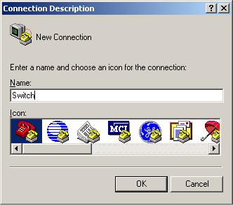
1.Select Start > All Programs > Accessories > Communications > HyperTerminal. The Connection Description dialog box appears.
2.Enter the name of the new connection in the Name field and click OK.
Figure 8 Connection description
3.Select the serial port to be used from the Connect using list, and click OK.
8
Loading...