


 Loading...
TM 11-6625-2965-14&P
TECHNICAL MANUAL
OPERATOR’S ORGANIZATIONAL
DIRECT SUPPORT AND GENERAL SUPPORT
MAINTENANCE MANUAL
[INCLUDING REPAIR PARTS
AND SPECIAL TOOLS LISTS]
POWER SUPPLY PP-7548/U
(HEWLETT-PACKARD MODEL 6205B]
[NSN 6625-00-437-4861]
HEADQUARTERS, |
DEPARTMENT |
OF |
THE |
ARMY |
25 FEBRUARY 1980
WARNING
HIGH VOLTAGE is used during the performance of maintenance as instructed in this manual. DEATH ON CONTACT may result if personnel fail to observe safety precautions.
DO NOT ATTEMPT to make internal connections or perform adjustments unless another person, capable of performing first aid, is present.
For electric shock protection, use only extension cord and power receptacles with a safety-ground connector, or otherwise connect the chassis to a safety ground.
CERTIFICATION
The Hewlett-Packard Company certifies that this instrument was thoroughly tested and inspected and found to meet its published specifications when it Was shipped from the factory. The Hewlett-Packard Company further certifies that its calibration measurements are traceable to the U.S. National Bureau of Standards to the extent allowed by the Bureau’s calibration facility.
WARRANTY AND ASSISTANCE
All Hewlett-Packard products are warranted against defects in materials and workmanship. This warranty applies for one year from the date of delivery, or, in the case of certain major components listed in the operating manual, for the specified period. We will repair or replace products which prove to be defective during the warranty period. No other warranty is expressed or implied. We are not liable for consequential damages.

T M 1 1 - 6 6 2 5 - 2 9 6 5 - 1 4 & P
This manual contains copyright material reproduced by permission of Hewlett-Packard Company
TECHNICAL M A N U A L |
HEADQUARTERS |
|
DEPARTMENT OF THE ARMY |
No. 11-6625-2965-14&P |
WASHINGTON, DC, 25 February 1980 |
OPERATOR’S, ORGANIZATIONAL, DIRECT SUPPORT AND
GENERAL SUPPORT MAINTENANCE MANUAL
(INCLUDING REPAIR PARTS AND SPECIAL TOOLS LISTS)
POWER SUPPLY PP-7548/U (HEWLETT-PACKARD MODEL)
(NSN 6625 - 00 - 437 - 4861)
REPORTING OF ERRORS
YOU can improve this manual by recommending improvements using DA Form 2028-2 located in the back of the manual. Simply tear out the self-addressed form, fill it out as shown on the sample, fold it where shown, and drop it in the mail.
If there are no blank DA Forms 2028-2 in the back of your manual, use the standard DA Form 2028 (Recommended Changes to Publications and Blank Forms) and forward to the Commander, US Army Communications and Electronics Materiel Readiness Command, ATTN: DRSEL-ME-MQ, Fort Monmouth, NJ 07703.
In either case a reply will be furnished direct to you.
This manual is an authentication of the manufacturer’s commercial literature which, through usage, has been found to cover the data required to operate and maintain this equipment. Since the manual was not prepared in accordance with military specifications, the format has not been structured to consider levels of maintenance.
|
|
|
|
|
|
|
|
|
|
|
|
|
|
|
TM |
11-6625-2965-14&P |
|||||
|
|
|
|
|
|
|
|
|
TABLE OF CONTENTS |
|
|
|
|
|
|
|
|
|
|
||
Section |
|
|
|
|
|
|
|
Page No. |
Section |
|
|
|
|
|
|
|
Page |
No. |
|||
O INSTRUCTIONS . . . . . . . . . . . . . . . . 0-1 |
3-38 |
Special |
Operating |
Con- |
|
|
|||||||||||||||
|
0-l |
Scope |
|
|
|
|
|
|
|
0-1 |
|
siderations |
|
|
|
|
3-6 |
||||
|
0-2 Indexes of Publications 0-1 |
3-39 |
Pulse Loading |
|
|
|
|
3-6 |
|||||||||||||
|
0-3 |
Maintenance |
Forms, |
0-1 |
3-41 |
Output |
Capacitance |
|
3-6 |
||||||||||||
|
|
Records |
and |
Reports |
3-43 |
Reverse |
Voltage |
Loading |
|
3-6 |
|||||||||||
|
0-4 |
Reporting |
Equipment |
|
3-45 |
Reverse |
Current |
Loading |
|
3-6 |
|||||||||||
|
|
Improvement |
|
Recommen- |
0-1 |
|
|
|
|
|
|
|
|
|
|
|
|||||
|
|
dations |
(EIR) |
|
IV PRINCIPLES OF OPERATION . . . . . . . . 4-1 |
||||||||||||||||
|
0-5 |
Administrative |
|
Storage |
0-1 |
||||||||||||||||
|
|
4-1 |
Overall |
Description |
|
4-1 |
|||||||||||||||
|
0-6 Destruction of Army |
|
|
||||||||||||||||||
|
|
4-8 |
Detailed |
Circuit |
Analysis |
|
4-2 |
||||||||||||||
|
|
Electronics |
|
Materiel |
0-1 |
|
|||||||||||||||
|
|
|
4-9 |
Feedback |
Loop |
|
|
|
4-2 |
||||||||||||
|
|
|
|
|
|
|
|
|
|
|
|
|
|
||||||||
|
|
|
|
|
|
|
|
|
|
|
4-13 |
Series Regulator |
|
|
|
4-2 |
|||||
|
|
|
|
|
|
|
|
|
|
|
4-15 |
Constant Voltage Comparator 4-2 |
|||||||||
I |
GENERAL INFORMATION . . . . . . . . . . . 1-1 |
4-19 |
Error |
Amplifier |
and Driver |
|
4-2 |
||||||||||||||
|
1-1 |
Description |
|
|
|
|
1-1 |
4-22 |
Current |
Limit |
Circuit |
|
4-3 |
||||||||
|
1 - 6 |
S p e c i f i c a t i o n s |
|
|
|
1-1 |
4-26 |
Reference |
|
Circuit |
|
|
4-3 |
||||||||
|
1 - 8 O p t i o n s |
|
|
|
|
|
1-1 |
4-29 |
Meter Circuit |
|
|
|
|
4-3 |
|||||||
|
1-10 |
Accessories |
|
|
|
|
1-2 |
V MAINTENANCE . . . . . . . . . . . . . . . . . . . 5-1 |
|||||||||||||
|
1-12 |
Instrument |
and |
Service Man- |
|
||||||||||||||||
|
|
ual Identification |
|
|
1-2 |
5-1 |
Introduction |
|
|
|
|
5-1 |
|||||||||
|
1-15 |
Ordering |
Additional Manuals |
1-2 |
5-3 |
General |
Measurement |
|
|
||||||||||||
II |
INSTALLATION . . . . . . . . . . . . . . . . . . . |
2-1 |
5-8 |
Techniques |
|
|
|
|
5-1 |
||||||||||||
Test |
Equipment |
Required |
|
5-2 |
|||||||||||||||||
|
2-1 |
Initia1 |
Inspection |
|
2-1 |
5-10 |
Performance Test |
|
|
5-3 |
|||||||||||
|
2-3 |
Mechanical Check |
|
|
2-1 |
5-12 |
Constant |
Voltage |
Tests |
|
5-3 |
||||||||||
|
2-5 |
Electrical Check |
|
|
|
2-1 |
5-38 |
Output |
Impedance |
|
|
5-7 |
|||||||||
|
2-7 |
Installation Data |
|
|
|
2-1 |
5-48 |
Troubleshooting |
|
|
|
5-9 |
|||||||||
|
2-9 |
Location |
|
|
|
|
|
2-1 |
5-53 |
Overa11 |
Troubleshooting |
|
|
||||||||
|
2-11 |
Outline |
Diagram |
|
|
2-1 |
|
Procedure |
|
|
|
|
|
5-9 |
|||||||
|
2-13 |
Rack |
Mounting |
|
|
|
2-1 |
5-58 |
Repair and |
Replacement |
|
5-12 |
|||||||||
|
2-17 |
Input |
Power |
Requirements |
2-3 |
5-60 |
Adjustment |
and |
Calibration |
|
5-13 |
||||||||||
|
2-19 |
Connections |
for |
230 Volt |
|
5-62 |
Meter Zero |
|
|
|
|
|
5-13 |
||||||||
|
|
Operation |
|
|
|
|
2-3 |
5-64 |
Ammeter |
Tracking |
|
|
5-13 |
||||||||
|
2-21 |
Power |
Cable |
|
|
|
2-3 |
5-66 |
Constant |
|
Voltage |
Programming |
|
|
|||||||
|
2-24 |
Repackaging |
for |
Shipment |
2-3 |
5-69 |
Current |
|
|
|
|
|
|
5-13 |
|||||||
I I I OPERATING INSTRUCTIONS . . . . . . . . 3-1 |
Reference |
|
Circuit |
Adjustments |
|
5-15 |
|||||||||||||||
5-71 |
Constant |
Voltage |
Transient |
|
|
||||||||||||||||
|
3-1 |
Turn-on Checkout Procedure |
3-1 |
|
Recovery |
Time |
|
|
|
5-15 |
|||||||||||
|
3-3 |
Operating |
Modes |
|
3-1 |
5-73 |
Current |
Limit |
Adjustment |
|
5-15 |
||||||||||
|
3-5 |
Norma1 |
Operating |
Mode |
3-1 |
|
|
|
|
|
|
|
|
|
|
|
|||||
|
3-7 |
Constant |
Voltage |
|
3-1 |
VI REPLACEABLE PARTS . . . . . . . . . . . . . . . |
6-1 |
||||||||||||||
|
3-9 |
Changing |
Current |
Limit |
3-2 |
6-1 |
Introduction |
|
|
|
|
|
6-1 |
||||||||
|
3-11 |
Connecting |
Load |
|
3-2 |
6-4 |
Ordering |
Information |
|
6-1 |
|||||||||||
|
3-14 |
Operation Beyond Norma 1 |
|
APPENDIX A |
References |
|
|
A-1 |
|||||||||||||
|
|
Rated |
Output |
|
|
|
3-2 |
|
|
||||||||||||
|
3-16 |
|
|
|
|
B |
Components |
of End |
|
|
|||||||||||
|
Optional |
Operating Modes |
3-2 |
|
|
B-1 |
|||||||||||||||
|
|
|
Item |
|
|
|
|
||||||||||||||
|
3-17 |
Remote |
Programming, Con- |
|
|
C |
|
|
|
|
|||||||||||
|
|
stant |
Voltage |
|
|
|
3-2 |
|
Maintenance |
C-1 |
|||||||||||
|
|
|
|
|
|
|
Allocation |
||||||||||||||
|
3-25 |
Remote |
Sensing |
|
|
3-3 |
|
D |
|||||||||||||
|
|
|
|
Manual |
backdating |
|
|
||||||||||||||
|
3-30 |
Series |
Operation |
|
3-4 |
|
|
|
|||||||||||||
|
|
|
|
Changes |
|
|
7-1 |
||||||||||||||
|
3-35 |
Auto-Tracking |
Operation |
3-5 |
VII CIRCUIT DIAGRAMS ........... |
||||||||||||||||
i i
TM 11-6625-2965-14&P
LIST OF ILLUSTRATIONS
Figure |
|
|
|
|
|
|
|
Page No. |
Figure |
|
2-1 |
Outline |
Diagram |
|
|
|
|
2-1 |
4-2 |
||
2-2 |
Rack |
Mounting, |
Two |
Units |
2-2 |
5-1 |
||||
2-3 |
Rack |
Mounting, |
One |
Unit |
2-2 |
|||||
2-4 |
Primary |
Connections |
|
|
2-3 |
5-2 |
||||
3-1 |
Front Panel Controls and Indicators |
3-1 |
5-3 |
|||||||
3-2 |
Normal |
Strapping |
Pattern |
3-1 |
||||||
3-3 |
Current |
Limit |
Alteration |
|
3-2 |
5-4 |
||||
3-4 |
Remote |
Resistance |
Programming |
3 - 3 |
||||||
3-5 |
Remote |
Voltage |
Programming |
3-3 |
5-5 |
|||||
3-6 |
Remote |
Sensing |
|
|
|
|
3-3 |
5-6 |
||
3-7 |
Norma I |
Series |
Connections |
3-4 |
5-7 |
|||||
3-8 |
Auto-Series, Two and |
Three Units |
3-4 |
5-8 |
||||||
3-9 Auto-Parallel, |
Two |
and |
Three |
3-5 |
5-9 |
|||||
3-10 |
Units |
|
|
|
|
|
|
|||
Auto-Tracking, Two and Three |
|
5-10 |
||||||||
4-1 |
Units |
|
|
|
|
|
|
3-5 |
||
Overa11 |
Block |
Diagram |
|
4-1 |
5-11 |
|||||
Page No.
Multiple |
Range |
Meter |
Circuit, |
|
|
||||
Simplified |
Schematic |
|
|
4-4 |
|||||
Front |
Panel |
Terminal |
Connections |
5-1 |
|||||
Output |
Current |
Measurement |
|
|
|||||
Technique |
|
|
|
|
|
5-1 |
|||
Differential |
Voltmeter |
Substitute, |
|
|
|||||
Test |
Setup |
|
|
|
|
|
5-2 |
||
Output |
Current, |
Test Setup |
5 |
-4 |
|||||
Load Regulation, |
Test |
Setup |
5-4 |
||||||
CV Ripple and Noise, Test Setup |
5-5 |
||||||||
CV Noise Spike, Test Setup |
5-6 |
||||||||
Transient |
Recovery |
Time, |
|
|
|
||||
Test |
Setup |
|
|
|
|
|
5-7 |
||
Transient |
Recovery |
Time, |
|
|
|
||||
Waveforms |
|
|
|
|
|
5-7 |
|||
Output |
Impedance, |
Test |
Setup |
5-8 |
|||||
Servicing |
Printed |
Wiring |
Boards |
5-14 |
|||||
LIST OF TABLES
Table |
|
|
|
|
|
Page No. |
1-1 |
Specifications |
|
1-3 |
|||
5-1 |
Test |
Equipment Required |
5-2 |
|||
5-2 |
Reference |
Circuit Troubleshooting |
5-9 |
|||
5-3 |
Overall Trouble shooting |
5-9 |
||||
5-4 |
High |
Output |
Voltage |
Troubleshooting |
5-11 |
|
5-5 |
Low |
Output |
Voltage |
Troubleshooting |
5-11 |
|
5-6 |
Selected |
Semiconductor Characteristics |
5-12 |
|||
5-7 |
Checks and Adjustments After Replacement |
of Semiconductor Devices 5-12 |
||||
6-1 |
Reference |
Designators |
6-1 |
|||
6-2 |
Description |
Abbreviations |
6-1 |
|||
6-3 |
Code |
List |
of |
Manufacturers |
6-2 |
|
6-4 |
Replaceable |
Parts |
|
6-5 |
||
i i i
TM 11-6625-2965-14&P
SECTION O
INSTRUCTIONS
0-1. SCOPE
This manual applies directly to Power Supply PP-7548/U (Hewlett-Packard Model 6205) having serial prefix number 7L2301 and up. For serial prefixes below 7L2301 refer to Appendix E. For serials above 7L4450 check for inclusion of change page.
0-2. INDEXES OF PUBLICATIONS
a.DA Pam 310-4. Refer to the latest issue of DA Pam 310-4 to determine
whether |
there are new editions , changes, or additional publications pertain- |
ing to |
the equipment. |
b. DA Pam 310-7. Refer to DA Pam 310-7 to determine whether there are modification work orders (MWOS) pertaining to the equipment.
0-3. MAINTENANCE FORMS, RECORDS AND REPORTS
a. Reports of Maintenance and Unsatisfactory Equipment. Department of the Army forms and procedures used for equipment maintenance will be those described by TM 38-750, The Army Maintenance Management System,
b.Report of Packaging and Handling Deficiencies. Fill out and forward DD Form 6 (Packaging Improvement Report) as prescribed in AR 700-58/
NAVSUPINST 4030.29/AFR 71-12/MCO P4030.29A, and DLAR 4145.8.
c.Discrepancy in Shipment Report (DISREP) (SF 361). Fill out and
forward Discrepancy in Shipment Report |
(DISREP) (SF 361) as prescribed in |
AR 55-38/NAVSUPINST 4610.33B/AFR 75-18/MCO P461O.19C and DLAR 4500.15. |
|
0-4. REPORTING EQUIPMENT IMPROVEMENT |
RECOMMENDATIONS(EIR) |
If your Power Supply PP-7548/U (HP-6205) needs improvement, let us know. Send us an EIR. You, the user, are the only one who can tell us what you don’t like about your equipment. Let us know why you don’t like the design. Tell us why a procedure is hard to perform. Put it on an SF 368 (Quality Deficiency Report). Mail it to Commander, US Army Communications and Electronics Materiel Readiness Command and Fort Monmouth, ATTN: DRSEL-ME- MQ, Fort Monmouth, New Jersey 07703. We'll send yOu a reply.
0 - 5 . ADMINISTRATIVE STORAGE
Administrative storage of equipment issued to and used by Army activities shall be in accordance with paragraph 2-5.
0-6. DESTRUCTION OF ARMY ELECTRONICS MATERIEL
Destruction of Army electronics materiel to prevent enemy use shall be in accordance with TM 750-244-2.
0-1
1-1 D E S C R I P T I O N
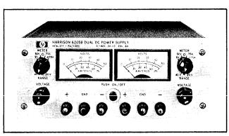
1-2 This power supply, Figure 1-1, is completely
transistorized and suitable |
for |
either bench or re- |
lay rack operations, The |
dual |
supply consists of |
two independently controlled dual range sections; both identical to the other. Each section can furnish either a 0-40 Volt output at 300mA or a 0-20 Volt output at 600mA. Each section has its own front panel meter and operating controls, The operating modes (40V or 20V) are selected by means of the front panel RANGE switches, The VOLTAGE controls permit each output voltage to be continuously adjusted throughout either output range.
Figure 1-1. DC Power Supply, Model 6205B
TM 11-6625-2965-14&P
may be programmed from a remote location by
means of |
an external voltage |
source |
or resistance. |
b. Remote Sensing. The degradation in |
|||
regulation |
which would occur |
at the |
load because |
of the voltage drop which takes place in the load leads can be reduced by using the power supply in the remote sensing mode of operation.
c. Series and Auto-Series Operation, Power
supplies may be used in series when |
a higher |
out- |
put voltage is required in the voltage |
mode of |
op- |
eration or when greater voltage compliance is required in the constant current mode of operation, Auto-Series operation permits one knob control of
the |
total |
output voltage from a “master” supply. |
|
||
|
d. Parallel and Auto-Parallel Operation, The |
||||
power supply may be operated in parallel with a |
|
||||
similar unit |
when greater output current capability |
||||
is required. |
Auto-Parallel operation permits one |
||||
knob control of the total output current from a |
|
||||
“master” |
supply. |
|
|
||
|
e. Auto-Tracking. The power supply may be |
||||
used as a “master” supply, |
having control over |
one |
|||
(or more) |
“slave” supplies |
that furnish various |
volt- |
||
ages for |
a system. |
|
|
||
1-6 |
SPECIFICATIONS |
|
|
||
1-7 |
Detailed |
specifications for the power supply |
|||
are |
given |
in |
Table 1-1. |
|
|
1 - 8 O P T I O N S
1-3 Both sections of the supply are of the regulated, Constant Voltage/Current Limiting, type. Each section is fully protected from overloads by the fixed current limit which is set by means of an internal adjustment.
1-4 Both front and rear terminals are available for each section. Either the positive or negative terminals may be grounded or the supply can be
operated at up to a maximum of 300 Volts off ground. Each meter can be used to measure either output voltage or output current in one of two ranges. The voltage or current ranges are selected by the ap-
plicable METER switch on the |
front panel. |
||
1-5 Two sets |
of |
programming |
terminals, located |
at the rear of |
the |
unit, allow ease in adapting to |
|
the many operational capabilities of the supply. A brief description of these capabilities is given below:
a, Remote Programming, The power supply
1-9 Options are factory modifications of a standard instrument that are requested by the customer. The following options are available for the instrument covered by this manual, Where necessary, de-
tailed coverage of |
the options is included through- |
|
out the |
manual. |
|
Option |
No. |
Description |
07 |
Voltage 10-Turn Pot: A single control |
|
|
that replaces both coarse and fine |
|
|
voltage controls and improves output |
|
|
nettability. |
|
11 |
Overvoltage_Protection_“Crowbar”: |
|
|
A completely separate circuit for pro- |
|
|
tecting delicate loads against power |
|
|
supply failure or operator error. This |
|
|
independent device monitors the out- |
|
|
put |
voltage and within 10µsec imposes |
|
a virtual short-circuit (crowbar) across |
|
|
the |
power supply output if the preset |
1 1

TM 11-6625-2965-14P
trip voltage is exceeded. When Option 11 is requested by the customer the device is connected at the factory.
Trip Voltage Range: 2.5 to 44 Volts, screwdriver adjustable.
Detailed coverage of Option 11 is included in Appendix A at the rear of manuals that support power supplies containing Option 11.
13 Three Digit Graduated Decadial Voltage Control: Control that replaces coarse and fine voltage controls permitting accurate resettability.
28 230Vac Input: Supply as normally shipped is wired for l15Vac input. Option 28 consists of reconnecting the input transformer for 230Vac operation.
1-10 ACCESSORIES
1-11 The accessories listed in the following chart may be ordered with the power supply or separately from your local Hewlett-Packard field sales office (refer to list at rear of manual for addresses).
Description
C05 8” Black Handle that can be attached to side of supply.
14513A Rack Kit for mounting one 3½” high supply. (Refer to Section II for details.)
14523A Rack Kit for mounting two 3½” high supplies. (Refer to Section II for details.)
1-12 INSTRUMENT AND SERVICE MANUAL IDENTIFICATION
1-13 Hewlett-Packard power supplies are identified by a three-part serial number tag. The first part is the power supply model number. The second part is the serial number prefix, which consists of a number-letter combination that denotes
the |
date of a |
significant design change. The num- |
ber |
designates |
the year, and the letter A through |
L designates the month, January through December respectively, with “I” omitted. The third part is the power supply serial number.
1-14 If the serial number prefix on your power supply does not agree with the prefix on the title page of this manual, change sheets are included to update the manual. Where applicable, backdating information is given in an appendix at the rear of the manual.
1-15 ORDERING ADDITIONAL MANUALS
1-16 One manual is shipped with each power supply, Additional manuals may be purchased from your local Hewlett-Packard field office (see list
at rear of this manual for addresses). Specify the model number, serial number prefix, and Part number provided on the title page.
1-2

TM 11-6625-2965-14&P
Table 1-1. Specifications
INPUT:
l15Vac ±10%, single phase, 48-440 Hz.
OUTPUT:
Two independent outputs, each of which can be set at either 0-40 Volts @ 0.3 Amp or 0-20 Volts @ 0.6 Amp.
LOAD REGULATION:
Less than 0,01% plus 4mV for a full load to no load change in output current.
LINE REGULATION:
Less than 0.01% plus 4mV for any line voltage change within the input rating.
RIPPLE AND NOISE:
Less than 200µVrms 1mV p-p,
TEMPERATURE RANGES:
operating: 0 to 50°C. Storage: -40 to + 750 C .
TEMPERATURE COEFFICIENT:
Less than 0.02% plus lmV per degree Centigrade.
STABILITY.
Less than 0.10% plus 5mV total drift for 8 hours after an initial warm-up time of 30 minutes at constant ambient, constant line voltage, and constant load.
INTERNAL IMPEDANCE AS A CONSTANT VOLTAGE SOURCE:
Less than 0.02 ohms from dc to lkHz. Less than 0.5 ohms from lkHz to 1OOkHz. Less than 3.0 ohms from 1OOkHz to lMHz.
TRANSIENT RECOVERY TIME: |
|
Less than 50µsec for output |
recovery to with- |
in 10mV following a full load |
current change in |
the output. |
|
OVERLOAD PROTECTION:
A fixed current limiting circuit protects the power supply for all overloads including a direct short placed across the terminals in constant voltage operation.
METERS:
Each front panel meter can be used as either a
0-50 or 0-5 Volt voltmeter or as a 0-0.75 or 0.075 Amp ammeter.
OUTPUT CONTROLS:
RANGE switches select desired operating mode for each section and coarse and fine VOLTAGE controls set desired output voltages.
OUTPUT TERMINALS:
Six “five-way” output posts (three for each section of supply) are provided on the front panel and two output terminal strips (one per section) are located on the rear of the chassis. A1l power supply output terminals are isolated from the chassis and either the positive or negative terminals may be connected to the chassis through separate ground terminals located on the output termina1 strips.
ERROR SENSING:
Error sensing is normally accomplished at the front terminals if the load is attached to the front or at the rear terminals if the load is attached to the rear terminals. Also, provisions are included on the rear termina1 strips for remote sensing.
REMOTE RESISTANCE PROGRAMMING: 200 ohms per Volt.
REMOTE VOLTAGE PROGRAM MING: 1 Volt per Volt.
COOLING:
Convection cooling is employed. The supply has no moving parts.
SIZE:
3 ~ ½ " H x 12-5/8" D x 8½ " W. Two of the units
can be mounted side by side in a standard 19” relay rack.
WEIGHT:
10 lbs, net, 13 lbs. shipping.
FINISH:
Light gray front panel with dark gray case.
POWER CORD:
A three-wire, five-foot power cord is provided with each unit.
1-3
TM 11-6625-2965-14&P
SECTION II
INSTALLATION
2-1 INITIAL INSPECTION
2-2 Before shipment, this instrument was inspected and found to be free of mechanical and electrical defects. As soon as the instrument is unpacked, inspect for any damage that may have occurred in transit. Save all packing materials until the inspection is completed. If damage is found, a claim should be filed with the carrier. Hewlett-Packard Sales and Service office should be notified.
2-3 MECHANICAL CHECK
2-4 This check should confirm that there are no broken knobs or connectors, that the cabinet and panel surfaces are free of dents and scratches,
and |
that the meter is not scratched or cracked. |
2-5 |
ELECTRICAL CHECK |
2-6 The instrument should be checked against its electrical specifications. Section V includes an
“ in-cabinet” performance check to verify proper instrument operation,
2-7 INSTALLATION DATA
2-8 The instrument is shipped ready for bench operation. It is necessary only to connect the instrument to a source of power and it is ready for operation.
2-9 LOCATION
2-10 This instrument is air cooled. Sufficient space should be allotted so that a free flow of cooling air can reach the sides and rear of the instrument when it is in operation. It should be used in an area where the ambient temperature does not exceed 50°C.
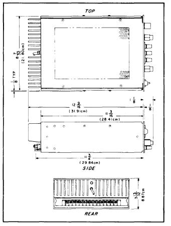
2-11 OUTLINE DIAGRAM
2-12 Figure 2-1 is an outline diagram showing the dimensions of the instrument.
2-13 RACK MOUNTING
2-14 This instrument may be rack mounted in a standard 19 inch rack panel either alongside a similar unit or by itself. Figures 2-2 and 2-3 show
Figure 2-1. Outline Diagram
how both types of installations are accomplished.
2-15 To mount two units |
side-by-side, |
proceed |
||
as follows: |
|
|
||
|
a . |
Remove the four |
screws from |
the front |
panels |
of |
both units. |
|
|
|
b. Slide rack mounting ears between the |
|||
front panel and case of each unit. |
|
|||
|
c . Slide combining strip between the front |
|||
panels |
and cases of the two units. |
|
||
|
d. After fastening rear portions of units to- |
|||
gether using the bolt, nut, and spacer, replace |
||||
panel |
screws. |
|
|
|
2-16 To mount a single unit in the rack panel, |
||||
proceed as follows: |
|
|
||
|
a. Bolt rack mounting ears, combining |
|||
straps, |
and angle brackets |
to each side |
of center |
|
2-1
TM 11-6625-2965-14&P
Figure 2-2. Rack Mounting, Two Units
Figure 2-3. Rack Mounting, One Unit
TM 11-6625-2965-14&P
spacing panels. Angle brackets are placed behind combining straps as shown in Figure 2-3.
b. Remove four screws from front panel of
unit.
c. Slide combining strips between front panel and case of unit.
d. Bolt angle brackets to front sides of case and replace front panel screws.
2-17 INPUT POWER REQUIREMENTS
2-18 This power supply may be operated from either a nominal 115 Volt or 230 Volt 48-440 Hertz power source. The unit, as shipped from the factory, is wired for 115 Volt operation. The input power required when operated from a 115 Volt 60 Hertz power source at full load is 31 Watts and 0.35 Amperes.
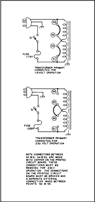
2-19 CONNECTIONS FOR 230 VOLT OPERATION
2-20 Normally, the two primary windings of the input transformer are connected in parallel for operation from 115 Volt source. To convert the power supply to operation from a 230 Volt source, the power transformer windings are connected in series as follows:
a . Unplug the line cord and remove the unit from case.
b. Break the copper between 54 and 55 and also between 50 and 51 on the printed circuit board. The se are shown in Figure 2-4, and are labeled on copper side of printed circuit board.
c . Add strap between 50 and 55.
d. Replace existing fuse with 1 Ampere, 230 Volt fuse. Return unit to case and operate normally.
2-21 POWER CABLE
2-22 To protect operating personnel, the National Electrical Manufacturers Association (NEMA) recommends that the instrument panel and cabinet be grounded. This instrument is equipped with a three conductor power cable. The third conductor is the ground conductor and when the cable is
plugged into an appropriate receptacle, the instrument is grounded. The offset pin on the power cable three-prong connector is the ground connection.
2-23 To preserve the protection feature when operating the instrument from a two-contact outlet, use a three-prong to two-prong adapter and connect the green lead on the adapter to ground.
2-24 REPACKAGING FOR SHIPMENT
2-25 To insure |
safe |
shipment of the instrument, it |
is recommended |
that |
the package designed for the |
Figure 2-4. Primary Connections
instrument be used. The original packaging mate-
rial |
is reusable. If it is not available, contact |
your |
local Hewlett-Packard field office to obtain |
the materials. This office will also furnish the address of the nearest service office to which the instrument can be shipped. Be sure to attach a tag to the instrument which specifies the owner, model number, full serial number, and service required, or a brief description of the trouble,
2-3
TM 11-6625-2965-14&P
SECTION Ill
OPERATING INSTRUCTIONS
3-1 TURN-ON CHECKOUT PROCEDURE
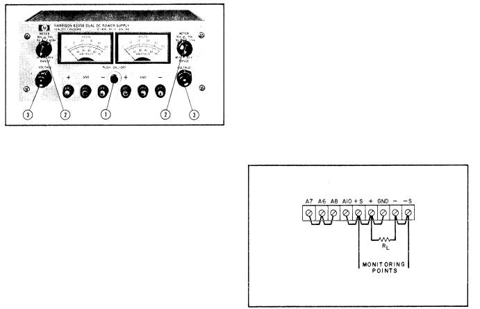
Figure 3-1. Front Panel Controls and Indicators
erational capabilities of the supply. A more theoretical description concerning these operational features is contained in Application Note 90 and in various Tech Letters. Copies of these can be obtained from your local Hewlett-Packard field office,
3-5 NORMAL OPERATING MODE
3-6 |
The |
power supply is normally shipped with |
its |
rear |
terminal strapping connections arranged |
for Constant Voltage/Current Limiting, local sensing, local programming, single unit mode of operation. This strapping pattern is illustrated in Figure 3-2. The operator selects a constant voltage output using the front panel controls (local programming, no strapping changes are necessary).
3-2 The front panel controls and indicators are shown in Figure 3-1. The normal turn-on sequence, is described below:
A. Push ON/OFF button that button lights,
B.Set range switch to desired operating mode and meter switch to desired voltage range.
C.Adjust coarse and fine voltage controls
until desired output voltage is indicated on meter.
D.Set meter switch to highest current range and short circuit output terminals.
E.Observe short circuit output current on
meter.
F.Remove short and connect load to output
terminals (front or rear),
G. For Model 6205B, this procedure should be used for both sections of supply.
3 - 3 O P E R A T I N G M O D E S
3-4 The power supply is designed so that its mode of operation can be selected by making strapping connections between particular terminals on the terminal strip at the rear of the power supply. The terminal designations are stenciled in white on the power supply above their respective terminals. Although the strapping patterns illustrated in this section show the positive terminal grounded, the operator can ground either termina1 or operate the power supply up to 300Vdc off ground (floating). The following paragraphs describe the procedures for utilizing the various op-
Figure 3-2. Norma 1 Strapping Pattern
3-7 CONSTANT VOLTAGE
3-8 To select a constant voltage output turn on the supply and, with no load connected, adjust the VOLTAGE controls for the desired output voltage. To check the current limit, connect an external ammeter across the output of the supply, turn the VOLTAGE controls fully clockwise, and observe the reading. The current limit is factory adjusted to approximately 100mA above the current
rating of the supply. |
If the |
existing |
current limit |
|
is not compatible with the anticipated load re- |
||||
quirements, the |
limit |
can be |
changed |
as outlined |
in the following |
paragraphs. |
|
|
|
3-1
TM 11-6625-2965-14&P
3-9 CHANGING CURRENT LIMIT
3-10 The current limit can be varied by adjusting resistor R81, located on the printed wiring board. This adjustment procedure is described in Paragraph 5-74. In Models 6204B and 6206B, the current limit may be reduced to a value lower than that attainable by adjusting R81, by adding an external resistor as shown in Figure 3-3. The ap-
proximate |
value of the |
external resistance (Rx) can |
||||
be determined |
by |
using |
the following equation |
|||
|
|
R X = 1 . 7 5 |
||||
|
|
|
|
IE |
|
|
where: IE |
= |
the |
output current |
|||
RI = the internal current sampling resist- |
||||||
|
ance |
for the particular operating mode |
||||
|
to be |
used. |
|
|
||
1.75 . |
the approximate voltage drop across |
|||||
|
|
the internal sampling resistance at |
||||
|
|
the |
current limit crossover point. |
|||
NOTE
The power supply’s performance will be somewhat degraded if it is operated too close to (within 10OmA) the current limit crossover point.
A1 A2 A6 A7 A8 A9 -S – GND + +S A10
R x |
R L |
Figure 3-3. Current Limit Alteration
3-11 CONNECTING LOAD
3-12 Each load should be connected to the power supply output terminals using separate pairs of connecting wires. This will minimize mutual coupling effects between loads and will retain full advantage of the low output impedance of the power supply. Each pair of connecting wires should be
as short as possible and twisted or shielded to reduce noise pickup. (If shield is used, connect one end to power supply ground terminal and leave the other end unconnected. )
3-13 If load considerations require that the output power distribution terminals be remotely located from the power supply, then the power supply output terminals should be connected to the remote distribution terminals via a pair of twisted or shielded wires and each load separately connected to the remote distribution termina1s. For this case, remote sensing should be used (Paragraph 3-25).
3-14 OPERATION BEYOND NORMAL RATED OUTPUT
3-15 Although the supply can deliver greater than the rated output on both the lower and higher voltage ranges without being damaged, it can not be guaranteed to meet all of its performance specifications. Generally when operating the supply in this manner, the output is unstable when connected to a load. When greater than the lower rated voltage is required, the higher voltage range should be used. This range will deliver half as much output current and all specifications will apply as listed in Table 1-1. However, if the line voltage is maintained above its nomina1 value, the supply will probably operate within specifications above its rated output.
3-16 OPTIONAL OPERATING MODES
3-17 REMOTE PROGRAMMING, CONSTANT VOLTAGE
3-18 The constant voltage output of the power supply can be programmed (controlled) from a remote location if required. Either a resistance or voltage source can be used for the programming device. The wires connecting the programming terminals of the supply to the remote programming device should be twisted or shielded to reduce noise pickup. The VOLTAGE controls on the front panel are disabled according to the following procedures.
3-19 Resistance Programming (Figure 3-4). In this mode, the output voltage will vary at a rate determined by the programming coefficient (200 ohms per Volt for Model 6204B and 6205B or 300 ohms per Volt for Model 6206 B). The output voltage will increase by 1 Volt for each 200 ohms (or 300 ohms) added in series with the programming terminals. The programming accuracy is 1% of the
programmed |
voltage. |
If greater programming ac- |
|
curacy is required, |
it |
may be achieved by chang- |
|
ing resistor |
R13 as |
outlined in Section V. |
|
3-20 The output voltage of the power supply should be zero Volts ± 20 millivolts when zero ohms is connected across the programming terminals . If a zero ohm voltage closer than this is re-
quired, |
it may be achieved by |
changing resistor |
R6 or |
R8 as described in Section |
V. |
3-2
A 7 A 6 A 8 A 1 0 + S + G N D - – S
PROGRAMMING |
R L |
R E S I S T O R |
|
Figure 3-4. Remote Resistance Programming
3-21 To maintain the stability and temperature coefficient of the power supply, u se programming resistors that have stable, low noise, and low temperature (less than 30ppm per degree Centigrade) characteristics. A switch can be used in conjunction with various resistance values in order to obtain discrete output voltages. The switch should have make-before-break contacts to avoid momentarily opening the programming terminals during the switching interval.
3-22 Voltage Programming (Figure 3-5). Employ the strapping pattern shown on Figure 3-5 for voltage programming. In this mode, the output voltage will vary in a 1 to 1 ratio with the programming voltage (reference voltage) and the load
on the programming voltage source will not exceed 25 microampere.
A7 A6 A8 A10 +S + GND - -S
REFERENCE
VOLTAGE
Figure 3-5. Remote Voltage Programming
3-23 The impedance (Rx) looking into the external
TM 11-6625-2965-14&P
programming voltage source should be approximately 1000 ohms if the temperature and stability specifications of the power supply are to be maintained. The programming accuracy is 1% of the programmed voltage.
3-24 Methods of voltage programming with gain
are discussed in Application Note 90, Power Supply Handbook; available at no charge from your local
 Sales Office.
3-25 REMOTE SENSING (See Figure 3-6)
3-26 Remote sensing is used to maintain good regulation at the load and reduce the degradation of regulation which would occur due to the voltage drop in the leads between the power supply and the load. Remote sensing is accomplished by utilizing the strapping pattern shown in Figure 3-6. The power supply should be turned off before changing strapping patterns. The leads from the +S terminals to the load will carry less than 10 milliamperes of current, and it is not required that these leads be as heavy as the load leads. H o w - ever, they must be twisted or shielded to minimize noise pick-up.
C A U T I O N
Observe polarity when connecting the sensing leads to the load.
A 7 A 6 A 8 A 1 0 + S + A N D – – S
R L
Figure 3-6. Remote Sensing
3-27 For reasonable load lead lengths, remote sensing greatly improves the performance of the supply. However, if the load is located a considerable distance from the supply, added precautions must be observed to obtain satisfactory operation. Notice that the voltage drop in the load leads sub-
3-3

TM 11-6625-2965-14&P
tracts directly from |
the available |
output voltage |
and also reduces the |
amplitude of |
the feedback er- |
ror signals that are developed within the unit. Because of these factors it is recommended that the drop in each load lead not exceed 1 Volt. If a larger drop must be tolerated, please consuIt a  sales engineer.
NOTE
Due to the voltage drop in the load leads, it may be necessary to readjust the current limit in the remote sensing mode.
3-28 Another factor that must be considered is the inductance of long load leads which could affect the stability of the feedback loop and cause oscillation. In these cases, it is recommended that the output capacitor (C20) be physically removed from the power supply and placed across the output terminals.
3-29 Although the strapping patterns shown in Figures 3-4 and 3-5 employ local sensing, notice that it is possible to operate a power supply simultaneously in the remote sensing and the remote programming modes.
3-30 SERIES OPERATION
3-31 Normal Series Connections (Figure 3-7). Two or more power supplies can be operated in
series to obtain a higher voltage |
than |
that avail- |
|||
able from a |
single |
supply. |
When |
this |
configuration |
is used, the |
output |
voltage |
is the |
sum |
of the volt- |
A 7 A 6 A 8 A 1 0 - S + G N D – – S
A 7 A 6 A 8 A 1 0 - S + G N D – – S
ages of the individual supplies. Each of the individual supplies must be adjusted in order to obtain the total output voltage. The power supply contains a protective diode connected internally across the output which protects the supply if one power supply is turned off while its series partner(s) is on.
3-32 Auto-Series Connections (Figure 3-8). The Auto-Series configuration is used when it is desirable to have the output voltage of each of the series connected supplies vary in accordance with the setting of a control unit. The control unit is called the master; the controlled units are called slaves . At maximum output voltage, the voltage of the slaves is determined by the setting of the front panel VOLTAGE control on the master. The
master supply must be the most positive |
supply of |
the series. The current limit settings of |
all series |
|
|
|
|
Figure 3-7. Normal Series Connections |
Figure 3-8, Auto-Series, Two and Three Units |
3-4
 6205B User Manual")
units are effective and the current limit for the entire configuration is equal to the lowest current limit setting. If any of the settings are too low, automatic crossover to current limiting operation will occur and the output voltage will drop. Remote sensing and programming can be used; however, the strapping arrangements shown in the applicable figures show local sensing and programming.
3-33 In order to maintain the temperature coefficient and stability specifications of the power
supply, the external resistors (Rx) shown in Figure
3-8 should be stable, low noise, low temperature coefficient (less than 30ppm per degree Centigrade)
resistors. The value of each resistor is dependant
on the maximum voltage rating of the master supply, The value of Rx is this voltage divided by the voltage programming current of the slave supply (l/Kp where Kp is the voltage programming coefficient). The voltage contribution of the slave is
TM 11-6625-2965-14&P
determined by its voltage |
control setting. |
|
||
3-34 Auto-Parallel. |
The |
strapping patterns |
for |
|
Auto-Parallel operation of two |
and three power sup- |
|||
plies are shown in |
Figure |
3 |
-9. Auto-Parallel |
op- |
eration permits equal current sharing under all load conditions, and allows complete control of the output current from one master power supply. The output current of each slave will be approximately equal to the master’s regardless of the load conditions. Because the output current controls of each slave are operative, they should be set to maximum to avoid having the slave revert to constant current operation; this would occur if the master output current setting exceeded the slave’s. In Model 6205B, it is necessary to make internal connections in order to operate the supply in this mode. The internal connections, specified in Figure 3-9, a r e made to the sampling terminals of the current sampling terminals of the current sampling resistor, R54 (see Figure 5-2).
3-5

not desired, set the preset limit for the peak requirement and not the average.
3-41 OUTPUT CAPACITANCE
3-42 An internal capacitor, acress the output terminals of the power supply, helps to supply highcurrent pulses of short duration during constant voltage operation. Any capacitance added externally will improve the pulse current capability, but will decrease the safety provided by the current
limiting |
circuit. |
A high-current pulse may damage |
load components |
before the average output current |
|
is large |
enough |
to cause the current limiting cir- |
cuit to |
operate. |
|
3-43 REVERSE VOLTAGE LOADING
3-44 A diode is connected across the output terminals. Under normal operating conditions, the diode is reverse biased (anode connected to neg-
ative terminal). If a reverse voltage is applied to
the output terminals (positive voltage applied to negative terminal), the diode will conduct, shunting current across the output terminals and limiting the voltage to the forward voltage drop of the diode. This diode protects the series transistors and the output electrolytic capacitors.
3-45 REVERSE CURRENT LOADING
3-46 Active loads connected to the power supply may actually deliver a reverse current to the power supply during a portion of its operating cycle. An external source cannot be allowed to pump current into the supply without loss of regulation and possible damage to the output capacitor. To avoid these effects, it is necessary to preload the supply with a dummy load resistor so that the power supply delivers current through the entire operating cycle of the load device.
3 - 6
TM 11-6625-2965-14&P
series |
regulator so |
that |
the output current is limited |
||
to the |
proper |
value. |
|
|
|
4-6 The reference circuit provides stable refer- |
|||||
ence |
voltages |
used |
in |
the constant voltage compar- |
|
ator |
and current limit |
circuits. The bias circuit |
|||
provides the less critical bias voltages used in the supply.
4-7 The meter circuit provides a continuous indication of output voltage or current in both ranges.
4-8 DETAILED CIRCUIT ANALYSIS
4-9 FEEDBACK LOOP
4-10 The feedback loop functions continuously to keep the output voltage constant during normal operation of the supply. For purposes of this discussion, assume that the output voltage instantaneously rises (goes positive) due to a variation in the external load circuit. Note that the change may be in the form of a slow rise in the output voltage or a positive going ac signal. An ac signal is coupled to summing point A6 through capacitor Cl and a dc voltage is coupled to A6 through R 10.
4-11 The rise in output voltage causes the voltage at A6 and thus the base of Q1A to decrease (go negative). Q1A now decreases its conduction and its collector voltage rises. The positive going error voltage is amplified and inverted by Q3 and fed to the base of the series transistor(s) via emitter follower Q4. The negative going input causes the series transistor(s) to decrease its conduction so that it drops more of the line voltage, reducing the
output |
voltage to its |
original |
level. |
|
||
4-12 |
If |
the external |
load |
resistance |
decreases to |
|
a certain |
crossover point, |
the |
supply |
will operate |
||
in the current limiting mode. In the current limit mode, Q1O conducts sending a negative going, turn-down signal to the series regulator via driver Q4 .
4-13 SERIES REGULATOR
4-14 The series regulator consists of transistor stage Q7 (and Q6 on Model 6206 B). The regulator serves as a series control element by altering its conduction so that the output voltage is kept constant and the current limit is never exceeded, The conduction of the transistor(s) is controlled by the feedback voltage obtained from driver Q4. Diode CR11, connected across the regulator circuit, pro-
tects |
the |
series transistor(s) against reverse volt- |
ages |
that |
could develop across it during parallel or |
auto-parallel operation if one supply is turned on before the other.
4-15 CONSTANT VOLTAGE COMPARATOR
4-16 The circuit consists of the coarse and fine programming resistors (Rl0A and R 10 B), and a differential amplifier stage (Ql and associated com-
ponents). Transistor Q1 consists of two transistors housed in a single package. The transistors have matched characteristics minimizing differential voltages due to mismatched stages. Moreover, drift due to thermal differentials is minimized, since both transistors operate at essentially the same temperature.
4-17 The constant voltage comparator continuously compares a fixed reference voltage with a por-
tion |
of the output voltage and, if a difference ex- |
ists, |
produces an error voltage whose amplitude |
and phase is proportional to the difference. The error output is fed back to the series regulator, through the (mixer) error and driver amplifiers. The error voltage changes the conduction of the series regulator which, in turn, alters the output voltage so that the difference between the two input voltages applied to the differential amplifier is reduced to zero. The above action maintains the output voltage constant.
4-18 Stage Q1B of the differential amplifier is connected to a common (+S) potential through impedance equalizing resistor R5. Resistors R6 and
R8 |
are |
used |
to zero bias the input stage, offset- |
|
ting minor base-to-emitter voltage |
differences in |
|||
Q1. |
The |
base |
of Q1A is connected |
to a summing |
point at the junction of the programming resistors and the current pullout resistors, R12 and R13. Instantaneous changes in output voltage result in an increase or decrease in the summing point potential. Q1A is made to conduct more or less, in accordance with summing point voltage change.
The resultant output |
error voltage is fed back |
to |
|||||
the |
series regulator |
via |
the remaining |
components |
|||
of |
the feedback |
loop. |
Resistor |
Rl, in |
series |
with |
|
the |
base Q1A, |
limits the current |
through the |
pro- |
|||
gramming resistors during rapid voltage turn-down. Diodes CR1 and CR2 form a limiting network which prevent excessive voltage excursions from over driving stage Q1A. Capacitor Cl, shunting the
programming resistors, increases the high frequen- |
|
cy gain of the input |
amplifier. Resistor R1 3, shunt- |
ing pullout resistor |
R12, is factory selected so |
that all of the + 6.2 Volt reference is dropped across R12 and R13. Linear constant voltage programming is assured with a constant current flowing through R1O. C20 stabilizes the feedback loop and may be removed to avoid current surges and increase the programming speed.
4-19 ERROR AMPLIFIER AND DRIVER
4-20 The error and driver amplifiers amplify the error signal from the constant voltage comparator circuit to a leve1 sufficient to drive the series regulator transistor(s). Driver Q4 also receives a current limiting input if Q10, the current limiting transistor, conducts.
4-2
4-21 Stage Q3 contains a feedback equalizer network, C5 and R30, which provides for high frequency roll off in the loop gain in order to stabilize the feedback loop. Q17 establishes a stable emitter bias potential for error amplifier Q3. Emitter follower transistor(s) Q4 (and Q5) serves as the driver (and predriver) element for the series regulator.
4-22 CURRENT LIMIT CIRCUIT
4-23 The current limit circuit limits the output
current |
to a preset value determined by the setting |
of R81. |
Switch S2B selects the proper sampling |
resistance to maintain an equal |
voltage drop acress |
the current sampling network in |
both ranges. |
4-24 When S2 is set to the 20 Volt position, R54 and R55 are connected in parallel. When S2 is set to the 40 Volt position, the current sampling network consists solely of R54. Note that in the twenty Volt range, twice as much current can be delivered as in the forty Volt range. Since the twenty Volt range has a sampling resistance equal to half the value of that for the forty Volt range, an equal sampling resistor voltage drop is obtained in both ranges. This also applies to S2 in the 6206B.
4-25 R81 sets the bias of Q10, and thus, the threshold point at which Q10 conducts and current limiting begins. If this threshold is exceeded, Q10
begins |
to conduct, forward |
biasing CR16 and send- |
ing a |
turn-down signal to |
the series regulater via |
the driver. If the current through the current sampling network decreases below the threshold point, Q10 turns off and no longer affects the operation of the supply.
4-26 REFERENCE CIRCUIT
4-27 The reference circuit (see schematic) is a feedback power supply similar to the main supply. It provides stable reference voltages which are used throughout the unit. The reference voltages are a 11 derived from smoothed dc obtained from the full wave rectifier (CR22 and CR23) and filter capacitor C10. The +6.2 and -6.2 voltages, which are used in the constant voltage input circuit for com-
parison purposes, are developed across temperature compensated Zener diodes VR1 and VR2. Resistor R43 limits the current through the Zener diodes to establish an optimum bias level.
TM 11-6625-2965-14&P
4-28 The reference circuit consists of series regulating transistor Q9 and error amplifier Q8. Output voltage changes are detected by Q8 whose base is connected to the junction of a voltage divider
(R41, R42) connected directly across the supply. Any error signals are amplified and inverted by Q8 and applied to the base of series transistor Q9.
The series element then alters its conduction in the direction, and by the amount, necessary to maintain the voltage across VR1 and VR2 constant. Resistor R46, the emitter resistor for Q8, is connected in a manner which minimizes changes in the reference voltage caused by variations in the input line. Output capacitor C9 stabilizes the regulator loop.
4-29 METER CIRCUIT (Figure 4-2)
4-30 The meter circuit provides continuous indications of output voltage or current on a single multiple range meter. The meter can be used either as a voltmeter or an ammeter depending upon the position of the METER section of switch S2 on the front panel of the supply. This switch also selects one of two meter ranges on each scale. The meter circuit consists of METER-RANGE switch S2, vari-
ous |
multiplying resistors and the meter movement. |
4-31 |
When measuring voltage, the meter is placed |
directly |
across the output of the supply between |
the +S |
and -S terminals. With the METER section |
of S2A in the higher voltage position (terminals A2 and A10) multiplying resistors R60, R61, R72, and the parallel combination of R73 and R87, are in series with the meter. For low output voltages, the METER switch S2A can be set to the first position (terminals 1 and 9) which removes R61 from its series position allowing a larger percentage of the output voltage to be felt acress the meter.
4-32 When measuring current; the meter circuit is connected across the current sampling resistor network as shown on Figure 4-2 and indicates the output current that flows through the network. The RANGE section S2B connects the appropriate re-
sistance in series with the meter |
so that its maxi- |
mum deflection range is full-scale |
in the high cur- |
rent (low voltage) operating mode |
and half-scale in |
the low current (high voltage) operating mode. This circuit obviates the need for a dual current scale which would be necessary since the voltages dropped across the current sampling network in both operating modes are equal for proportional currents.
4-3
Loading...