


 Loading...
SERVICE MANUAL
AUTORANGING
SYSTEM DC POWER SUPPLY
HP MODELS 6033A and 6038A
HP Part No. 5959-3346
FOR INSTRUMENTS WITH SERIAL NUMBERS
HP Model 6033A; Serials US38320231 and above
HP Model 6038A; Serials US38310401 and above
For instruments with higher serial numbers, a change page may be included.
Microfiche Part No. 5959-3347 |
Printed in USA: December, 1999 |

CERTIFICATION
Hewlett-Packard Company certifies that this product met its published specifications at time of shipment from the factory. Hewlett-Packard further certifies that its calibration measurements are traceable to the United States National Bureau of Standards, to the extent allowed by the Bureau’s calibration facility, and to the calibration facilities of other International Standards Organization members.
WARRANTY
This Hewlett-Packard hardware product is warranted against defects in material and workmanship for a period of three years from date of delivery. HP software and firmware products, which are designated by HP for use with a hardware product and when properly installed on that hardware product, are warranted not to fail to execute their programming instructions due to defects in material and workmanship for a period of 90 days from date of delivery. During the warranty period HewlettPackard Company will, at its option, either repair or replace products which prove to be defective. HP does not warrant that the operation of the software, firmware, or hardware shall be uninterrupted or error free.
For warranty service, with the exception of warranty options, this product must be returned to a service facility designated by HP. Customer shall prepay shipping charges by (and shall pay all duty and taxes) for products returned to HP for warranty service. Except for products returned to Customer from another country, HP shall pay for return of products to Customer.
Warranty services outside the country of initial purchase are included in HP’s product price, only if Customer pays HP international prices (defined as destination local currency price, or U.S. or Geneva Export price).
If HP is unable, within a reasonable time to repair or replace any product to condition as warranted, the Customer shall be entitled to a refund of the purchase price upon return of the product to HP.
LIMITATION OF WARRANTY
The foregoing warranty shall not apply to defects resulting from improper or inadequate maintenance by the Customer, Customer-supplied software or interfacing, unauthorized modification or misuse, operation outside of the environmental specifications for the product, or improper site preparation and maintenance. NO OTHER WARRANTY IS EXPRESSED OR IMPLIED. HP SPECIFICALLY DISCLAIMS THE IMPLIED WARRANTIES OF MERCHANTABILITY AND FITNESS FOR A PARTICULAR PURPOSE.
EXCLUSIVE REMEDIES
THE REMEDIES PROVIDED HEREIN ARE THE CUSTOMER’S SOLE AND EXCLUSIVE REMEDIES. HP SHALL NOT BE LIABLE FOR ANY DIRECT, INDIRECT, SPECIAL, INCIDENTAL, OR CONSEQUENTIAL DAMAGES, WHETHER BASED ON CONTRACT, TORT, OR ANY OTHER LEGAL THEORY.
ASSISTANCE
The above statements apply only to the standard product warranty. Warranty options, extended support contracts, product maintenance agreements and customer assistance agreements are also available. Contact your nearest Hewlett-Packard Sales and Service office for further information on HP’s full line of Support Programs.
2

SAFETY SUMMARY
The following general safety precautions must be observed during all phases of operation, service and repair of this instrument. Failure to comply with these precautions or with specific warnings elsewhere in this manual violates safety standards of design, manufacture, and intended use of the instrument. Hewlett-Packard Company assumes no liability for the customer’s failure to comply with these requirements.
BEFORE APPLYING POWER.
Verify that the product is set to match the available line voltage and the correct fuse is installed.
GROUND THE INSTRUMENT.
This product is a Safety Class 1 instrument (provided with a protective earth terminal). To minimize shock hazard, the instrument chassis and cabinet must be connected to an electrical ground. The instrument must be connected to the ac power supply mains through a threeconductor power cable, with the third wire firmly connected to an electrical ground (safety ground) at the power outlet. For instruments designed to be hard wired to the ac power lines (supply mains), connect the protective earth terminal to a protective conductor before any other connection is made. Any interruption of the protective (grounding) conductor or disconnection of the protective earth terminal will cause a potential shock hazard that could result in personal injury. If the instrument is to be energized via an external autotransformer for voltage reduction, be certain that the autotransformer common terminal is connected to the neutral (earth pole) of the ac power lines (supply mains).
FUSES
Only fuses with the required rated current, voltage, and specified type (normal blow, time delay, etc.) should be used. Do not use repaired fuses or short circuited fuseholders. To do so could cause a shock or fire hazard.
DO NOT OPERATE IN AN EXPLOSIVE ATMOSPHERE.
Do not operate the instrument in the presence of flammable gases or fumes.
KEEP AWAY FROM LIVE CIRCUITS.
Operating personnel must not remove instrument covers. Component replacement and internal adjustments must be made by qualified service personnel. Do not replace components with power cable connected. Under certain conditions, dangerous voltages may exist even with the power cable removed. To avoid injuries, always disconnect power, discharge circuits and remove external voltage sources before touching components.
DO NOT SERVICE OR ADJUST ALONE.
Do not attempt internal service or adjustment unless another person, capable of rendering first aid and resuscitation, is present.
DO NOT EXCEED INPUT RATINGS.
This instrument may be equipped with a line filter to reduce electromagnetic interference and must be connected to a properly grounded receptacle to minimize electric shock hazard. Operation at the line voltage or frequencies in excess of those stated on the data plate may cause leakage currents in excess of 5.0mA peak.
SAFETY SYMBOLS.
Instruction manual symbol: the product will be marked with this symbol when it is necessary for the user to refer to the instruction manual (refer to Table of Contents) .
Indicates hazardous voltages.
Indicate earth (ground) terminal.
The WARNING sign denotes a hazard. It calls attention to a procedure, practice, or the like, which, if not correctly performed or adhered to, could result in personal injury. Do not proceed beyond a WARNING sign until the indicated conditions are fully understood and met.
The CAUTION sign denotes a hazard. It calls attention to an operating procedure, or the like, which, if not correctly performed or adhered to, could result in damage to or destruction of part or all of the product. Do not proceed beyond a CAUTION sign until the indicated conditions are fully understood and met.
DO NOT SUBSTITUTE PARTS OR MODIFY INSTRUMENT.
Because of the danger of introducing additional hazards, do not install substitute parts or perform any unauthorized modification to the instrument. Return the instrument to a Hewlett-Packard Sales and Service Office for service and repair to ensure that safety features are maintained.
Instruments which appear damaged or defective should be made inoperative and secured against unintended operation until they can be repaired by qualified service personnel.
3
TABLE OF CONTENTS |
|
Introduction ............................................................................................................................................................................ |
9 |
Scope .................................................................................................................................................................................... |
9 |
Calibration and Verification ............................................................................................................................................. |
9 |
Troubleshooting................................................................................................................................................................ |
9 |
Principles of Operation ..................................................................................................................................................... |
9 |
Replaceable Parts.............................................................................................................................................................. |
9 |
Circuit Diagrams............................................................................................................................................................... |
9 |
Safety Considerations ........................................................................................................................................................... |
9 |
Manual Revisions ............................................................................................................................................................... |
10 |
Firmware Revisions ............................................................................................................................................................ |
10 |
Calibration and Verification................................................................................................................................................ |
11 |
Introduction ........................................................................................................................................................................ |
11 |
Test Equipment Required ................................................................................................................................................... |
11 |
Operation Verification Tests............................................................................................................................................... |
11 |
Calibration Procedure ......................................................................................................................................................... |
11 |
Initial Setup..................................................................................................................................................................... |
14 |
Voltage Monitor Zero Calibration .................................................................................................................................. |
15 |
Common Mode Calibration ............................................................................................................................................ |
15 |
Remote Readback Zero Calibration................................................................................................................................ |
16 |
Constant Voltage Full Scale Calibration......................................................................................................................... |
16 |
Voltage Monitor and Remote Readback Full Scale Calibration ..................................................................................... |
17 |
Constant Voltage Zero Calibration ................................................................................................................................. |
17 |
Current Monitor Zero Calibration................................................................................................................................... |
17 |
Constant Current Zero Calibration.................................................................................................................................. |
18 |
Current Monitor Full Scale Calibration .......................................................................................................................... |
18 |
Constant Current Full Scale Calibration ......................................................................................................................... |
19 |
Power Limit Calibration ................................................................................................................................................. |
19 |
Resistance Programming Full Scale Calibration............................................................................................................. |
19 |
Performance Tests .............................................................................................................................................................. |
20 |
Measurement Techniques ............................................................................................................................................... |
20 |
Constant Voltage (CV) Tests .......................................................................................................................................... |
21 |
Constant Current (CC) Tests........................................................................................................................................... |
26 |
Initialization Procedure....................................................................................................................................................... |
28 |
Troubleshooting .................................................................................................................................................................... |
29 |
Introduction ........................................................................................................................................................................ |
29 |
Initial Troubleshooting Procedures..................................................................................................................................... |
29 |
Electrostatic Protection....................................................................................................................................................... |
30 |
Repair and Replacement ..................................................................................................................................................... |
30 |
A2 Control Board Removal ............................................................................................................................................ |
31 |
A4 FET Board Removal ................................................................................................................................................. |
31 |
A8 HP-IB Board Removal.............................................................................................................................................. |
32 |
A3 Front-Panel Board Removal...................................................................................................................................... |
32 |
A1 Main Board Removal................................................................................................................................................ |
32 |
Overall Troubleshooting Procedure.................................................................................................................................... |
33 |
HP-IB Section Troubleshooting.......................................................................................................................................... |
33 |
Primary Interface Troubleshooting ..................................................................................................................................... |
36 |
Secondary Interface Troubleshooting ................................................................................................................................. |
38 |
Voltage and Current DAC .............................................................................................................................................. |
38 |
Readback DAC Circuits.................................................................................................................................................. |
39 |
Readback Multiplexer (U20): ......................................................................................................................................... |
39 |
5
Signature Analysis .............................................................................................................................................................. |
41 |
Primary SA ..................................................................................................................................................................... |
41 |
Front Panel SA................................................................................................................................................................ |
41 |
Secondary SA ................................................................................................................................................................. |
42 |
Power Section Troubleshooting.......................................................................................................................................... |
47 |
Main Troubleshooting Setup .......................................................................................................................................... |
48 |
Troubleshooting No-Output Failures .............................................................................................................................. |
49 |
Power Section Blocks ..................................................................................................................................................... |
50 |
Troubleshooting AC-Turn-On Circuits........................................................................................................................... |
53 |
Troubleshooting DC-To-DC Converter .......................................................................................................................... |
53 |
Troubleshooting Bias Supplies ....................................................................................................................................... |
54 |
Troubleshooting Down Programmer .............................................................................................................................. |
57 |
Troubleshooting CV Circuit ........................................................................................................................................... |
58 |
Troubleshooting CC Circuit............................................................................................................................................ |
58 |
Troubleshooting OVP Circuit......................................................................................................................................... |
59 |
Troubleshooting PWM & Clock..................................................................................................................................... |
59 |
Principles of Operation ........................................................................................................................................................ |
61 |
Introduction ........................................................................................................................................................................ |
61 |
HP-IB Board....................................................................................................................................................................... |
61 |
Primary Microprocessor ................................................................................................................................................. |
61 |
Address Switches........................................................................................................................................................... |
61 |
EEPROM........................................................................................................................................................................ |
63 |
Isolation .......................................................................................................................................................................... |
63 |
Secondary Microprocessor ............................................................................................................................................. |
63 |
Digital-to-Analog Converters ......................................................................................................................................... |
63 |
Analog Multiplexer......................................................................................................................................................... |
63 |
Status Inputs ................................................................................................................................................................... |
63 |
Front Panel Board............................................................................................................................................................... |
64 |
Address Latches and Decoders ....................................................................................................................................... |
64 |
Volts and Amps Output Ports and Displays.................................................................................................................... |
64 |
RPG and Latches ............................................................................................................................................................ |
64 |
Front-Panel Switches and Input Port .............................................................................................................................. |
64 |
Mode Indicators.............................................................................................................................................................. |
66 |
OVP Adjust Control ....................................................................................................................................................... |
66 |
Power Clear .................................................................................................................................................................... |
66 |
Power Mesh and Control Board.......................................................................................................................................... |
66 |
Overview ........................................................................................................................................................................ |
66 |
AC Turn-On Circuits ...................................................................................................................................................... |
68 |
DC-to-DC Converter....................................................................................................................................................... |
68 |
Down Programmer.......................................................................................................................................................... |
69 |
Bleeder Circuit (6038A only) ......................................................................................................................................... |
69 |
Constant-Voltage (CV) Circuit ....................................................................................................................................... |
69 |
Constant-Current (CC) Circuit........................................................................................................................................ |
70 |
Overvoltage Protection (OVP) Circuit............................................................................................................................ |
70 |
Power-Limit Comparator ................................................................................................................................................ |
70 |
Control-Voltage Comparator .......................................................................................................................................... |
70 |
Initial-Ramp Circuit ........................................................................................................................................................ |
71 |
Pulse-Width Modulator (PWM) ..................................................................................................................................... |
71 |
Bias Voltage Detector..................................................................................................................................................... |
71 |
AC-Surge-&-Dropout Detector....................................................................................................................................... |
71 |
1-Second-Delay Circuit .................................................................................................................................................. |
72 |
Replaceable Parts ................................................................................................................................................................. |
73 |
Introduction ........................................................................................................................................................................ |
73 |
6
Ordering Information.......................................................................................................................................................... |
74 |
|
Component Location and Circuit Diagrams ...................................................................................................................... |
91 |
|
l00 Vac Input Power Option 100 ......................................................................................................................................... |
99 |
|
General Information............................................................................................................................................................ |
99 |
|
Description ..................................................................................................................................................................... |
99 |
|
Scope of Appendix A...................................................................................................................................................... |
99 |
|
Suggestions for Using Appendix A................................................................................................................................. |
99 |
|
Chapter 1 |
Manual Changes ............................................................................................................................................. |
99 |
Chapter 2 |
Manual Changes ............................................................................................................................................. |
99 |
Chapter 3 |
Manual Changes: .......................................................................................................................................... |
101 |
Chapter 4 |
Manual Changes: .......................................................................................................................................... |
101 |
Chapter 5 and 6 Manual Changes ................................................................................................................................. |
102 |
|
Blank Front Panel Option 001........................................................................................................................................... |
103 |
|
Introduction |
...................................................................................................................................................................... |
103 |
Troubleshooting............................................................................................................................................................ |
103 |
|
Chapter 2 .......................................................................................................................................... |
Manual Changes: |
103 |
Chapter 3 .......................................................................................................................................... |
Manual Changes: |
104 |
Chapter 5 ................................................................................................................................and 6 Manual Changes: |
104 |
|
7

1
Introduction
Scope
This manual contains information for troubleshooting the HP 6033A/6038A 200W Autoranging Power Supply to the component level. Wherever applicable, the service instructions given in this manual refer to pertinent information provided in the Operation Manual (P/N 5959-3301). Both manuals cover HP Models 6033A/6038A; differences between models are described as required.
The following information is contained in this manual.
Calibration and Verification
Contains calibration procedures for HP Models 6033A/6038A. Also contains verification procedures that check the operation of the supplies to ensure they meet the specifications of Chapter 1 in the Operating Manual.
Troubleshooting
Contains troubleshooting procedures to isolate a malfunction to a defective component on the main circuit board or to a defective assembly (front panel, power transformer, or cable assembly). Board and assembly level removal and replacement procedures are also given in this section.
Principles of Operation
Provides block diagram level descriptions of the supply’s circuits. The primary interface, secondary interface, and the power mesh and control circuits are described. These descriptions are intended as an aid in troubleshooting.
Replaceable Parts
Provides a listing of replaceable parts for all electronic components and mechanical assemblies for HP Models 6033A/6038A.
Circuit Diagrams
Contains functional schematics and component location diagrams for all HP 6033A/6038A circuits. The names that appear on the functional schematics also appear on the block diagrams in Chapter 2. Thus, the descriptions in Chapter 2 can be correlated with both the block diagrams and the schematics.
Safety Considerations
This product is a Safety Class 1 instrument, which means that it is provided with a protective earth terminal. Refer to the Safety Summary page at the beginning of this manual for a summary of general safety information. Safety information for specific procedures is located at appropriate places in the manual.
9

Manual Revisions
Hewlett-Packard instruments are identified by a 10-digit serial number. The format is described as follows: first two letters indicate the country of manufacture. The next four digits are a code that identify either the date of manufacture or of a significant design change. The last four digits are a sequential number assigned to each instrument.
Item Description
US The first two letters indicates the country of manufacture, where US = USA.
3648 This is a code that identifies either the date of manufacture or the date of a significant design change.
0101 The last four digits are a unique number assigned to each power supply.
If the serial number prefix on your unit differs from that shown on the title page of this manual, a yellow Manual Change sheet may be supplied with the manual. It defines the differences between your unit and the unit described in this manual. The yellow change sheet may also contain information for correcting errors in the manual.
Note that because not all changes to the product require changes to the manual, there may be no update information required for your version of the supply.
Older serial number formats used with these instruments had a two-part serial number, i.e. 2701A-00101. This manual also applies to instruments with these older serial number formats. Refer to Appendix E for backdating information.
Firmware Revisions
The primary and secondary interface microcomputer chips inside of your supply are identified with labels that specify the revision of the supply’s firmware. This manual applies to firmware revisions A.00.00, A.00.01, and A.00.02.
10
2
Calibration and Verification
Introduction
This section provides test and calibration procedures. The operation-verification tests comprise a short procedure to verify that the unit is performing properly, without testing all specified parameters. After troubleshooting and repair of a defective power supply you can usually verify proper operation with the turn-on checkout procedure in the Operating Manual. Repairs to the A1 main board, the A2 control board and the A8 HP-IB board can involve circuits which, although functional, may prevent the unit from performing within specified limits. So, after A1, A2 or A8 board repair, decide if recalibration and operation verification tests are needed according to the faults you discover. Use the calibration procedure both to check repairs and for regular maintenance.
Test Equipment Required
Table 2-1 lists the equipment required to perform the tests of this section. You can separately identify the equipment for performance tests, calibration and troubleshooting using the USE column of the table.
Operation Verification Tests
To assure that the unit is performing properly, without testing all specified parameters, first perform the turn-on checkout procedure in the Operating Manual. Then perform the following performance tests, in this section.
Voltage Programming And Readback Accuracy
Current Programming And Readback Accuracy
CV Load Effect
CC Load Effect
Calibration Procedure
Calibrate the unit twice per year and when required during repair. The following calibration procedures should be performed in the sequence given.
Note: Some of the calibration procedures for this instrument can be performed independently, and some procedures must be performed together and/or in a prescribed order. If a procedure contains no references to other procedures, you may assume that it can be performed independently.
To return a serviced unit to specifications as quickly as possible with minimal calibration, the technician need only perform calibration procedures that affect the repaired circuit. Table 2-2 lists various power supply circuits with calibration procedures that should be performed after those circuits are serviced.
If the HP-IB board (A8) has been replaced, you must first initialize the board before you can calibrate the unit. Refer to Page 28.
11

TYPE
Oscilloscope
RMS Voltmeter
Logic Pulser
Multimeter
Signature Analyzer
HP-IB Controller
Current Probe
Electronic Load
Power Resistor*
Current-Monitoring
Shunts
Calibration and Test
Resistors
Terminating
Resistors (2)
Blocking
Capacitors (2)
Common-mode
Toroidal Core
Table 2-1. Test Equipment Required |
|
||
|
|
|
|
REQUIRED CHARACTERISTICS |
USE |
|
RECOMMENDED MODEL |
Sensitivity: 1 mV |
P,T |
|
HP54504A |
Bandwidth: 20MHz & 100MHz |
|
|
|
Input: differential, 50 W & 10MW |
|
|
|
True rms, 10MHz bandwidth |
P |
|
HP3400A |
Sensitivity: 1 mV Accuracy: 5% |
|
|
|
4.5 to 5.5Vdc @ 35mA |
T |
|
HP546A |
Resolution: 100nV |
P,C,T |
|
HP 3458A |
Accuracy: 0.0035%, 6½ digit |
|
|
|
-- |
T |
|
HP 5004A |
Full HP-IB capabilities |
C,T,P |
|
HP Series, 200/300 |
No saturation at 30Adc |
P |
|
Tektronix P6303 Probe/ |
Bandwidth: 20Hz to 20MHz |
|
|
AM503 Amp/ |
|
|
|
TM500 Power Module |
Voltage range: 60Vdc |
P,C |
|
HP 6060A |
Current range: 30Adc |
|
|
|
Power range: 250W |
|
|
|
Open and short switched |
|
|
|
Value: 0.25W >200W (6033A) |
P,C |
|
|
Value: 2.3W >200W (6038A) |
|
|
|
Value: 10mW ± 0.04% @ 100W (6033A) |
P,C** |
|
Guildline 9230/100 |
PC: 0.0004%/W |
|
|
|
Value: 100mW ± 0.04% @ 25W (6038A) |
|
|
Guildline 9230/15 |
PC: 0.0004%/W |
|
|
|
Value: 100W, 5%, 1W |
C,T |
|
|
1W, 5%, ½W |
|
|
|
1KW, 5%, ¼W |
|
|
|
2KW, 0.01%, ¼W |
|
|
|
Value: 50W ±5%, noninductive |
P |
|
|
|
|
|
|
Value: 0.01mF, 100Vdc |
P |
|
|
|
|
|
|
³3.7mH/turn2 |
P |
|
Ferrox-Cube |
@23mm I.D. |
|
|
500T600-3C8, |
|
|
|
HP 9170-0061 |
Switch* |
SPST, 30A @60V |
P |
|
DC Power Supply |
Voltage range: 0-60Vdc |
C,T |
HP 6024A |
|
Current range: 0-3Adc |
|
|
P = performance testing C = calibration adjustments |
T = troubleshooting |
||
*Not required if using electronic load.
**Less accurate, and less expensive, current-monitor resistors can be used, but the accuracy to which current programming and readback can be checked must be reduced accordingly.
12

|
|
Table 2-2. Guide to Recalibration After Repair |
|||
|
|
|
|
|
|
|
Printed Circuit |
Block Name |
Ref. |
Perform These Procedures |
|
|
Board |
|
Desig. |
|
|
A1 |
Main Board |
|
R3 |
Current Monitor Full Scale Calibration |
|
|
|||||
|
|
|
|
Constant Current Full Scale Calibration |
|
A1 |
Main Board |
|
T1 |
Power Limit Calibration |
|
|
|||||
A4 |
Power Mesh Board |
|
T3 |
Power Limit Calibration |
|
|
|||||
A4 |
Power Mesh Board |
|
CR7 |
Power Limit Calibration |
|
|
|||||
A2 |
Control Board |
Constant Voltage Circuit |
All |
Voltage Monitor Zero Calibration |
|
|
|
(All Except Current Source) |
|
Common Mode Calibration |
|
|
|
|
|
Remote Readback Zero Calibration |
|
|
|
|
|
Constant Voltage Full Scale Calibration |
|
|
|
|
|
Voltage Monitor and Remote Readback Full |
|
|
|
|
|
Scale Calibration |
|
|
|
|
|
Constant Voltage Zero Calibration |
|
A2 |
Control Board |
Constant Voltage Circuit |
All |
Resistance Programming Full Scale Calibration |
|
|
|
(Current Source) |
|
|
|
A2 |
Control Board |
Constant Current Circuit |
All |
Current Monitor Zero Calibration |
|
|
|
|
|
Constant Current Zero Calibration |
|
|
|
|
|
Current Monitor Full Scale Calibration |
|
|
|
|
|
Constant Current Full Scale Calibration |
|
A2 |
Control Board |
Power Limit Comparator |
All |
Power Limit Calibration |
|
A2 |
Control Board |
Bias Power Supplies |
All |
All Calibration Procedures |
|
|
|
( + & -15V Supplies) |
|
|
|
A8 |
HP-IB Board |
Voltage Monitor Buffer |
All |
Voltage Monitor Zero Calibration |
|
|
|
|
|
Remote Readback Zero Calibration |
|
|
|
|
|
Constant Voltage Full Scale Calibration |
|
|
|
|
|
Voltage Monitor and Remote Readback Full |
|
|
|
|
|
Scale Calibration |
|
|
|
|
|
Constant Voltage Zero Calibration |
|
A8 |
HP-IB Board |
Analog Multiplexer |
All |
Remote Readback Zero Calibration |
|
|
|
|
|
Constant Voltage Full Scale Calibration |
|
|
|
|
|
Voltage Monitor and Remote Readback Full |
|
|
|
|
|
Scale Calibration |
|
|
|
|
|
Constant Voltage Zero Calibration |
|
A8 |
HP-IB Board |
Readback DAC |
All |
Remote Readback Zero Calibration |
|
|
|
|
|
Constant Voltage Full Scale Calibration |
|
Voltage Monitor and Remote Readback Full
Scale Calibration
Constant Voltage Zero Calibration
13

Table 2-2. Guide to Recalibration After Repair (continued)
Printed Circuit |
Block Name |
Ref. |
Perform These Procedures |
|
Board |
|
Desig. |
|
|
A8 HP-IB Board |
Voltage DAC |
All |
Remote Readback Zero Calibration |
|
|
|
|
Constant Voltage Full Scale Calibration |
|
|
|
|
Voltage Monitor and Remote Readback Full |
|
|
|
|
Scale Calibration |
|
|
|
|
Constant Voltage Zero Calibration |
|
A8 HP-IB Board |
Current DAC |
All |
Constant Current Zero Calibration |
|
|
|
|
Constant Current Full Scale Calibration |
|
A8 HP-IB Board |
|
U5 |
Remote Readback Zero Calibration |
|
|
||||
|
|
|
Constant Voltage Full Scale Calibration |
|
|
|
|
Voltage Monitor and Remote Readback Full |
|
|
|
|
Scale Calibration |
|
|
|
|
Constant Voltage Zero Calibration |
|
|
|
|
Constant Current Full Scale Calibration |
Initial Setup
a.Unplug the line cable and remove the top cover by removing the three screws; the rear handle screw and the two top- rear-corner screws. Do not remove the front handle screw as the retaining nut will fall into the unit.
b.Slide the cover to the rear.
c.Plug a control board test connector A2J3 onto the A2J3 card-edge fingers.
d.Turn OVERVOLTAGE ADJUST control A3R59 fully clockwise.
e.Disconnect all loads from output terminals.
f.Connect power supply for local sensing, and ensure that MODE switches are set as shown below.
g.Connect an HP-IB controller to the power supply.
h.Reconnect line cable and turn on ac power.
i.Allow unit to warm up for 30 minutes.
j.When attaching the DVM, the minus lead of the DVM should be connected to the first node listed, and the plus lead should be connected to the second node listed.
k.At the beginning of each calibration procedure, the power supply should be in its power-on state (turn ac power off and back on), with no external circuitry connected except as instructed.
l.The POWER LIMIT adjustment (A2R25) must be adjusted at least coarsely before many of the calibration procedures can be performed. If you have no reason to suspect that the Power Limit circuit is out of adjustment, do not change its setting. Otherwise, center A2R25 before you begin to calibrate the power supply.
m.Turn off ac power when making or removing connections to the power supply.
14
Maintenance described herein is performed with power supplied to the instrument, and protective covers removed. Such maintenance should be performed only by trained service personnel who are aware of the hazards involved (for example, fire and electrical shock). Where maintenance can be performed without power applied, the power should be removed.
Voltage Monitor Zero Calibration
a.Send string "VSET 0; ISET 0; OUT OFF".
b.Short power supply output terminals.
c.Attach the DVM from  M on the rear panel through a 1kΩ resistor to A2P3 pin 3 (V-MON1).
d.Adjust A2R22 (V-MON ZERO) to 0V ±20μV.
Common Mode Calibration
a.Send string ’’VSET 0; ISET 0; OUT OFF".
b.Short power supply sense terminals ( + S to - S) at rear panel.
c.Attach the DVM from  M on the rear panel through a 1kΩ resistor to A2J3 pin 3 (V-MON).
d.Take initial reading from DVM.
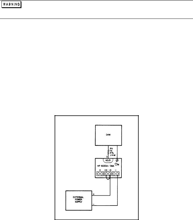
e.Remove both local sensing straps from rear-panel terminal block, and connect a 1-volt external power supply with its +
lead to - S and its--lead to - Out. See Figure 2-1.
Adjust A2R21 (CV LOAD REG) to Initial Reading ±20μV.
f.Replace local sense straps after removing external power supply.
Figure 2-1. Common Mode Setup
15
Remote Readback Zero Calibration
Note: This procedure and the following three procedures must be done as a set, without omitting any of the four procedures. Also, the following four procedures require that V-MON ZERO (A2R22) be adjusted within specifications. If it is not, perform the Voltage Monitor Zero Calibration before proceeding.
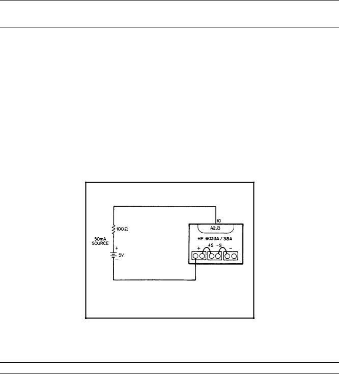
a.Connect an external supply to the power supply as shown in Figure 2-2.
b.Send string "VSET 0; ISET 5; OUT ON’’.
c.Attach the DVM from  M on the rear panel through a 1KΩ resistor to A2J3 pin 3 (V-MON).
d.Adjust A8R40 (CV PROG ZERO) to 625μV ± 30μV.
e.Remove the DVM.
f.Enter and run the following program and begin noting the controller’s display:
10 OUTPUT 705; "VOUT’’
20 ENTER 705; A
30 DISP A
40 GOTO 10
50END
g. Adjust A8R51 (READBACK ZERO) until the value displayed on the controller toggles between:
0and 5mV (6033A).
0and 15mV (6038A).
h.After adjusting A8R51 you must continue the calibration procedure through to the completion of Constant Voltage Zero Calibration. Remember to disconnect the external power supply and resistor.
Figure 2-2. Remote Readback Zero And CV Zero Calibration Setup
Constant Voltage Full Scale Calibration
Note: Perform this procedure only after completing Remote Readback Zero Calibration.
a.Remove all external test circuits.
b.Send string:
"VSET 200; ISET 5; OUT ON" (6033A). "VSET 60; ISET 5; OUT ON" (6038A).
16

c.Attach the DVM from - S to + S terminals on rear panel.
d.Adjust A8R58 (CV PROG F.S.) to:
20.0025 ±600μV (6033A).
60.0075 ±1.82mV (6038A).
e.After adjusting A8R58 you must continue the calibration procedure through to the completion of Constant Voltage Zero Calibration.
Voltage Monitor and Remote Readback Full Scale Calibration
Note: Perform this procedure only after completing Constant Voltage Full Scale Calibration.
a.Attach the DVM from  M on the rear panel to A2J3 pin 3 (V-MON). See DVM connection in Figure 2-1.
b. Send string: |
’’VSET 20; ISET 5; OUT ON’’ (6033A). |
|
’’VSET 60; ISET 5; OUT ON’’ (6038A). |
c.Adjust A8R75 (V-MON F.S.) to 5.000625V ±100μV.
d.Disconnect the DVM.
e.Enter and run the following program and begin noting the controller’s display. 10 OUTPUT 705; ’’VOUT?’’
20 ENTER 705; A
30 DISP A
40 GOTO 10
50 END
f.Adjust A8R61 (READBACK F.S.) until the value displayed on the controller toggles between: 20V and 20.005V (6033A).
60V and 60.015V (6038A).
g.After adjusting A8R61 you must continue the calibration procedure through to the completion of Constant Voltage Zero Calibration.
Constant Voltage Zero Calibration
Note: Perform this procedure only after completing Voltage Monitor and Remote Readback Full Scale Calibration.
a.Send string "VSET 0; ISET 5; OUT ON".
b.Connect an external supply to the power supply as shown in Figure 2-2.
c.Attach the DVM from - S to + S on the rear panel.
d.Adjust A8R40 (CV PROG ZERO) to 0 ±120μV.
Current Monitor Zero Calibration
a.Send string "VSET 0; ISET 0; OUT OFF’’.
b.Connect a short across power supply output terminals.
c.Attach the DVM from  M to IM on the rear panel.
d.Allow several minutes (3 or more) to ensure thermal settling.
e.Adjust A2R8 (I-MON ZERO) to:
0V ±100μV (6033A).
0V ±25μV (6038A).
17
Constant Current Zero Calibration
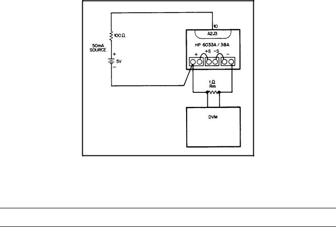
a.Connect the test setup shown in Figure 2-3.
b.Send string ’’VSET 5; ISET 0; OUT ON’’.
c.Allow several minutes (3 or more) to ensure thermal settling.
d.Adjust A8R29 (CC PROG ZERO) to:
0V ±1mV (6033A).
0V ±350μV (6038A).
Figure 2-3. CC Zero Calibration Setup
Current Monitor Full Scale Calibration
Note: This procedure requires that I-MON ZERO (A2R8) be adjusted within specifications. If it is not, perform the Current Monitor Zero Calibration before proceeding.
a.Connect Rm current-monitoring shunt: (10 milliohm, 6033A)
(100 milliohm, 6038A)
0.05% or better across power supply output terminals.
b.Send string:
"VSET 5; ISET 30; OUT ON" (6033A). "VSET 5; ISET 10; OUT ON" (6038A).
c.Attach DVM from  M to IM on the rear panel. Use six-digit display on HP 3458A DVM.
d.Take initial reading from DVM.
e.Attach DVM across Rm. Allow several minutes (3 or more) to ensure thermal settling. This can be noted as a stable reading on the DVM.
f.Adjust A2R9 (I-MON F.S.) to:
0.060 x initial reading ±0.4mV (6033A).
0.200 x initial reading ±1.0mV (6038A).
18

Constant Current Full Scale Calibration
Note: This procedure requires that CC PROG ZERO (A8R29) and I-MON F. S. (A2R9) be adjusted within specifications. If they are not, perform Constant Current Zero and/or Current Monitor Full Scale Calibration before proceeding.
a.Connect Rm current-monitoring shunt: (10 milliohm, 6033A)
(100 milliohm, 6038A)
0.05% or better across power supply output terminals.
b.Send string:
"VSET 5; ISET 30; OUT ON" (6033A). "VSET 5, ISET 10; OUT ON’’ (6038A).
c.Attach DVM across Rm. Allow several minutes (3 or more) to ensure thermal settling.
d.Adjust A8R55 (CC PROG F.S.) to:
300mV ±30μV (6033A). 100mV ±100μV (6038A).
Power Limit Calibration
Note: This procedure requires that CC PROG F. S. (A8R55) be adjusted within specifications. If it is not, perform Constant Current Full Scale Calibration before proceeding.
a.Connect the power supply to the ac power line through a variable autotransformer which is set to the minimum for your line voltage (e.g. 104V for nominal 120V line).
b.Turn A2R25 (POWER LIMIT) fully counterclockwise.
c.Connect a electronic load across the output terminals, or use a:
0.25Ω 200W resistor (6033A). 2.3Ω 200W resistor (6038A).
d.Set the electronic load for: 30 amperes (6033A). 10 amperes (6038A).
in the constant Current mode.
e.Turn on power supply and send string:
"VSET 9; ISET 30.5; OUT ON" (6033A). ’’VSET 23; ISET 10.2; OUT ON’’ (6038A).
f.Adjust A2R25 (POWER LIMIT) clockwise until CV LED on front panel turns on.
Resistance Programming Full Scale Calibration
a.Send string ’’OUT OFF".
b.Connect a 2-kilohm calibration resistor from  P to VP on rear panel.
c.Set rear-panel MODE switches for resistance programming:
19

d.Attach the DVM from  P to VP on the rear panel.
e.Adjust A2R23 (R-PROG F.S.) to 2.5V ±4mV.
f.Remember to reset MODE switches to original settings.
Performance Tests
The following paragraphs provide test procedures for verifying the unit’s compliance with the specifications of Table 1-1 in the Operating Manual. Please refer to CALIBRATION PROCEDURE or TROUBLESHOOTING if you observe out-of-specification performance. The performance test specifications are listed in the Performance Test Record in Appendix C and D. You can record the actual measured values in the columns provided.
Measurement Techniques
Setup For All Tests. Measure the output voltage directly at the + S and - S terminals. Connect unit for local sensing, and ensure that MODE switches are set as shown below. Select an adequate wire gauge for load leads using the procedures given in the Operating Manual for connecting the load.
Electronic Load. The test and calibration procedures use an electronic load to test the unit quickly and accurately. If an electronic load is not available, you may substitute:
2Ω 200W load resistor (6033A). 18Ω 200W load resistor (6038A).
for the electronic load in these tests:
CV Source Effect (Line Regulation).
CC Load Effect (Load Regulation).
You may substitute:
0.25Ω 200W load resistor (6033A). 2.3Ω 200W load resistor (6038A).
in these tests:
CV Load Effect (Load Regulation) CV PARD (Ripple and Noise)
CC Source Effect (Line Regulation) CC PARD (Ripple and Noise)
The substitution of the load resistor requires adding a load switch and making minor changes to the procedures. The load transient recovery time test procedure is not amenable to modification for use with load resistors.
An electronic load is considerably easier to use than a load resistor. It eliminates the need for connecting resistors or rheostats in parallel to handle the power, it is much more stable than a carbon-pile load, and it makes easy work of switching between load conditions as is required for the load regulation and load transient-response tests.
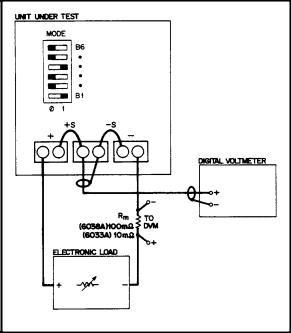
Current-Monitoring Resistor. To eliminate output current measurement error caused by voltage drops in the leads and connections, connect the current-monitoring resistor between -OUT and the load as a four-terminal device. Figure 2-4 shows correct connections. Connect the current-monitoring test leads inside the load-lead connections directly at the monitoring resistor element.
20
Note: A current-monitoring resistor with 1% accuracy is suitable for all tests except current programming accuracy and current readback accuracy. For these tests, use the shunt listed in Table 2-1.
Figure 2-4. Current-Monitoring Resistor Setup
HP-IB Controller. Most performance tests can be performed using only front-panel controls. However, an HP-IB controller is required to perform the voltage and current programming accuracy tests and the voltage and current readback accuracy tests.
Constant Voltage (CV) Tests
CV Setup. If more than one meter or a meter and an oscilloscope are used, connect each to the + S and - S terminals by a separate pair of leads to avoid mutual coupling effects. Connect only to + S and -S because the unit regulates the output voltage between + S and - S, not between + OUT and -OUT. Use coaxial cable or shielded 2-wire cable to avoid pickup on test leads. For all CV tests set the output current at full output to assure CV operation.
Voltage Programming And Readback Accuracy. This procedure verifies that the voltage programming and readback functions are within specifications. An HP-IB controller must be used for this test.
a.Connect digital voltmeter between + S and - S.
b.Turn on ac power to the power supply.
c.Send string:
’’VSET 0.1; ISET 30’’ (6033A).
’’VSET 0.09; ISET 10" (6038A).
d. The DVM reading should be in the range: 0.090 to 0.109Vdc (6033A).
0.050 to 0.130Vdc (6038A). Note the reading.
e.Enter and run the following program: 10 OUTPUT 705; "VOUT?"
20 ENTER 705;A
30 DISP A
40 GOTO 10
50 END
f.The value displayed by the controller should be the value noted in step d:
±0.006Vdc (6033A).
±0.015Vdc (6038A).
g.Send string:
"VSET 20; ISET 30" (6033A).
’’VSET 60; ISET 10" (6038A).
h. The DVM reading should be in the range: 19.984 to 20.016Vdc (6033A). 59.939 to 60.061Vdc (6038A).
Note the reading.
21
i.Run the program listed in step e. The value displayed by the controller should be the value noted in step h:
±0.02Vdc (6033A).
±0.092Vdc (6038A).
Load Effect (Load Regulation). Constant-voltage load effect is the change in dc output voltage (Eo) resulting from a load-resistance change from open-circuit to full-load. Full-load is the resistance which draws the maximum rated output current at voltage Eo. Proceed as follows:
a.Connect the test equipment as shown in Figure 2-5. Operate the load in constant resistance mode (Amps/Volt) and set resistance to maximum.
b.Turn the unit’s power on, and, using DISPLAY SETTINGS pushbutton switch, turn up current setting to full output.
c.Turn up output voltage to:
7.0Vdc (6033A). 20.0Vdc (6038A).
as read on the digital voltmeter.
Figure 2-5. Basic Test Setup
d.Reduce the resistance of the load to draw an output current of: 29Adc (6033A).
10 Adc (6038A).
Check that the unit’s CV LED remains lighted.
e.Open-circuit the load.
f.Record the output voltage at the digital voltmeter.
g.Reconnect the load.
h.When the reading settles, record the output voltage again. Check that the two recorded readings differ no more than:
±0.0027Vdc (6033A).
±0.005Vdc (6038A).
Source Effect (Line Regulation). Source effect is the change in dc output voltage resulting from a change in ac input voltage from the minimum to the maximum value as specified in Input Power Requirements in the Specifications Table, in the Operating Manual. Proceed as follows:
22
a.Connect the test equipment as shown in Figure 2-5. Operate the load in constant resistance mode (Amps/Volt) and set resistance to maximum.
b.Connect the unit to the ac power line through a variable autotransformer which is set for nominal line voltage.
c.Turn the unit’s power on, and, using DISPLAY SETTINGS pushbutton switch, turn up current setting to full output.
d.Turn up output voltage to:
20.0Vdc (6033A). 60.0Vdc (6038A).
as read on the digital voltmeter.
e.Reduce the resistance of the load to draw an output current of: 10Adc (6033A).
3.3Adc (6038A).
Check that the unit’s CV LED remains lighted.
f.Adjust autotransformer to the minimum for your line voltage.
g.Record the output voltage at the digital voltmeter.
h.Adjust autotransformer to the maximum for your line voltage.
i.When the reading settles record the output voltage again. Check that the two recorded readings differ no more than:
±0.003Vdc (6033A).
±0.008Vdc (6038A).
PARD (Ripple And Noise). Periodic and random deviations (PARD) in the unit’s output-ripple and noise-combine to produce a residual ac voltage superimposed on the dc output voltage. Constant-voltage PARD is specified as the root-mean-square (rms) or peak-to-peak (pp) output voltage in a frequency range of 20Hz to 20MHz.
RMS Measurement Procedure. Figure 2-6 shows the interconnections of equipment to measure PARD in Vrms. To ensure that there is no voltage difference between the voltmeter’s case and the unit’s case, connect both to the same ac power outlet or check that the two ac power outlets used have the same earth-ground connection.
Use the common-mode choke as shown to reduce ground-loop currents from interfering with measurement. Reduce noise pickup on the test leads by using 50Ω coaxial cable, and wind it five turns through the magnetic core to form the common-mode choke. Proceed as follows:
a.Connect the test equipment as shown in Figure 2-6. Operate the load in constant resistance mode (Amps/Volt) and set resistance to maximum.
b.Turn the unit’s power on, and, using DISPLAY SETTINGS pushbutton switch, turn up current setting to full output.
c.Turn up output voltage to:
7Vdc (6033A). 20Vdc (6038A).
d.Reduce the resistance of the load to draw an output current of: 29Adc (6033A).
10Adc (6038A).
Check that the unit’s CV LED remains lighted.
e.Check that the rms noise voltage at the true rms voltmeter is no more than 30mV rms.
Peak-To-Peak Measurement Procedure. Figure 2-7 shows the interconnections of equipment to measure PARD in Vpp. The equipment grounding and power connection instructions on Page 23 apply to this setup also. Connect the oscilloscope to the + S and - S terminals through 0.01μF blocking capacitors to protect the oscilloscope’s input from the unit’s output voltage. To reduce common-mode noise pickup, set up the oscilloscope for a differential, two-channel voltage measurement. To reduce normal-mode noise pickup, use matched-length, 1 meter or shorter, 50Ω coaxial cables with shields connected to the oscilloscope case and to each other at the other ends. Proceed as follows:
23

Figure 2-6. RMS Measurement Test Setup, CV PARD Test
Figure 2-7. Peak-To-Peak Measurement Test Setup, CV PARD Test
24
a.Connect the test equipment as shown in Figure 2-7. Operate the load in constant resistance mode (Amps/Volt) and set resistance to maximum.
b.Turn the unit’s power on, and, using DISPLAY SETTINGS pushbutton switch, turn up current setting to full output.
c.Turn up output voltage to:
7Vdc (6033A). 20Vdc (6038A).
d.Turn up output current setting to full output and reduce the resistance of the load to draw an output current of: 29Adc (6033A).
10Adc (6038A).
Check that the unit’s CV LED remains lighted.
e.Set the oscilloscope’s input impedance to 50Ω and bandwidth to 20MHz. Check that the peak-to-peak is no more than 30mV.
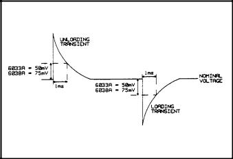
Load Transient Recovery Time. Specified for CV operation only; load transient recovery time is the time for the output voltage to return to within a specified band around its set voltage following a step change in load.
Use the equipment setup of Figure 2-5 to display output voltage transients while switching the load between 10% with the output set at:
6.7Vdc (6033A). 20Vdc (6038A).
Proceed as follows:
a.Connect the test equipment as shown in Figure 2-5. Operate the load in constant-current mode and set for minimum current.
b.Turn the unit’s power on, and, using DISPLAY SETTINGS pushbutton switch, turn up current setting to full output.
c.Turn up output voltage to:
6.7Vdc (6033A). 20.0Vdc (6038A).
as read on the digital voltmeter.
d.Set the load to vary the load current between: 27Adc and 30Adc (6033A).
9Adc and 10 Adc (6038A).
at a 30Hz rate for the 10% RECOVERY TEST.
e.Set the oscilloscope for ac coupling, internal sync and lock on either the positive or negative load transient.
f.Adjust the oscilloscope to display transients as in Figure 2-8.
g.Check that the amplitude of the transient pulse at 1 ms is no more than:
50mV (6033A). 75mV (6038A).
25
.
Figure 2-8. Load Transient Recovery Waveform
Constant Current (CC) Tests
CC Setup. Constant-current tests are analogous to constant-voltage tests, with the unit’s output short circuited and the voltage set to full output to assure CC operation. Follow the general setup instructions of Page 20.
Current Programming And Readback Accuracy. This procedure verifies that the current programming and readback functions are within specifications. An HP-IB controller must be used for this test. The accuracy of the current shunt resistor (Rm) must be 0.02% or better. Proceed as follows:
a.Connect test setup shown in Figure 2-5, except replace the load with a short circuit.
b.Turn on ac power to the power supply.
c.Send string:
"VSET 20; ISET 1.0" (6033A). ’’VSET 60; ISET 0.5" (6038A).
d.Check that the voltage across Rm is in the range: 9.79mV to 10.22mV (6033A).
48.9mV to 51.0mV (6038A). Note the reading.
e.Enter and run the following program:
10 OUTPUT 705; "IOUT?’’
20 ENTER 705; A
30 DISP A
40 GOTO 10
50END
f.The value displayed by the controller should be the actual output current ± 0.025Adc.
g.Send string:
’’VSET 20; ISET 30" (6033A). ’’VSET 60; ISET 10" (6038A).
h.Check that the voltage across Rm is in the range: 0.29935 to 0.30065Vdc (6033A).
1.0019 to 0.9982Vdc (6038A). Note the reading.
i.Run the program listed in step e.
j.The value displayed by the controller should be the actual output current:
±0.115Adc (6033A).
±0.031Adc (6038A).
26
Load Effect (Load Regulation). Constant current load effect is the change in dc output current (Io) resulting from a load-resistance change from short-circuit to full-load, or full-load to short-circuit. Full-load is the resistance which develops the maximum rated output voltage at current Io. Proceed as follows:
a.Connect the test equipment as shown in Figure 2-5. Operate the load in constant resistance mode (Amps/Volt) and set resistance to minimum.
b.Turn the unit’s power on, and, using DISPLAY SETTINGS pushbutton switch, turn up voltage setting to full output.
c.Turn up output current to:
10Adc (6033A). 3Adc (6038A).
d. Increase the load resistance until the output voltage at +S and -S decreases to: 20Vdc (6033A).
60Vdc (6038A).
Check that the CC LED is lighted and AMPS display still reads ≈ 10 amps.
e.Short-circuit the load and allow the voltage across Rm to stabilize.
f.Record voltage across Rm.
g.Disconnect short across load.
h.When the reading settles (≈ 10s), record the voltage across Rm again. Check that the two recorded readings differ no more than:
±100μVdc (6033A).
±530μVdc (6038A).
Source Effect (Line Regulation). Constant current source effect is the change in dc output current resulting from a change in ac input voltage from the minimum to the maximum values listed in the Specifications Table in the Operating Manual. Proceed as follows:
a.Connect the test equipment as shown in Figure 2-5. Operate the load in constant resistance mode (Amps/Volt) and set resistance to minimum.
b.Connect the unit to the ac power line through a variable autotransformer set for nominal line voltage.
c.Switch the unit’s power on and turn up output voltage setting to full output.
d.Turn up output current to:
30Adc (6033A). 10Adc (6038A).
e.Increase the load resistance until the output voltage between + S and - S decreases to: 7.0Vdc (6033A).
20.0Vdc (6038A).
Check that the CC LED is still on.
f.Adjust autotransformer to the minimum for your line voltage.
g.Record the voltage across Rm.
h.Adjust autotransformer to the maximum for your line voltage.
i.When the reading settles record the voltage across Rm again. Check that the two recorded readings differ no more than:
90μVdc (6033A).
300μVdc (6038A).
PARD Ripple And Noise. Periodic and random deviations (PARD) in the unit’s output (ripple and noise) combine to produce a residual ac current as well as an ac voltage super-imposed on the dc output. The ac voltage is measured as constant-voltage PARD, Page 23. Constant-current PARD is specified as the root-mean-square (rms) output current in a frequency range 20Hz to 20MHz with the unit in CC operation. To avoid incorrect measurements, with the unit in CC operation, caused by the impedance of the electronic load at noise frequencies, use a:
0.25Ω (6033A)
2.3Ω (6038A)
load resistor that is capable of safely dissipating 200 watts. Proceed as follows:
a.Connect the test equipment as shown in Figure 2-9.
b.Switch the unit’s power on and turn the output voltage all the way up.
c.Turn up output current to:
27

29Adc (6033A). 10Adc (6038A).
Check that the unit’s CC LED remains lighted.
d. Check that the rms noise current measured by the current probe and rms voltmeter is no more than: 15mA rms (6033A).
5mA rms (6038A).
Initialization Procedure
Follow the procedure if either the HP-IB assembly has been replaced, or the EEPROM (U70) has been replaced:
1.Install the HP-IB assembly in the unit.
2.Turn the power on and depending on your unit’s model number, send string:
"EEINIT 6033" or
"EEINIT 6038’’.
3.Turn the power off, wait 5 seconds, then turn the power back on.
4.If the HP-IB assembly has been replaced, calibrate the unit.
Figure 2-9. CC PARD Test Setup
28

3
Troubleshooting
Maintenance described herein is performed with power supplied to the instrument, and protective covers removed. Such maintenance should be performed only by service-trained personnel who are aware of the hazards involved (for example, fire and electrical shock). Where maintenance can be performed without power applied, the power should be removed.
Introduction
Before attempting to troubleshoot this instrument, ensure that the fault is with the instrument itself and not with an associated circuit. The performance test enables this to be determined without having to remove the covers from the supply.
The most important aspect of troubleshooting is the formulation of a logical approach to locating the source of trouble. A good understanding of the principles of operation is particularly helpful, and it is recommended that Chapter 4 of this manual be reviewed before attempting to troubleshoot the unit. Often the user will then be able to isolate a problem simply by using the operating controls and indicators. Once the principles of operation are understood, refer to the following paragraphs.
Table 2-1 lists the test equipment for troubleshooting. Chapter 6 contains schematic diagrams and information concerning the voltage levels and waveforms at many of the important test points. Most of the test points used for troubleshooting the supply are located on the control board test "fingers", which are accessible close to the top of the board. See Table 3-9.
If a component is found to be defective, replace it and re-conduct the performance test. When a component is replaced, refer to Calibration Procedure (Chapter 2). It may be necessary to perform one or more of the adjustment procedures after a component is replaced.
Initial Troubleshooting Procedures
If a problem occurs, follow the steps below in sequence:
a.Check that input power is available, and check the power cord and rear-panel line fuse.
b.Check that the settings of mode switch A2S1 are correct for the desired mode of operation. (See Operating Manual).
c.Check that all connections to the power supply are secure and that circuits between the supply and external devices are not interrupted.
d.Check that the rear-panel HP-IB address switch A8S1 is properly set. (See Operating Manual).
e.If the power supply fails turn-on self-test or gives any other indication of malfunction, remove the unit from the operating system before proceeding with further testing.
Some circuits on the power mesh are connected directly to the ac power line. Exercise extreme caution when working on energized circuits. Energize the supply through an isolation transformer to avoid shorting ac energized circuits through the test instrument’s input leads. The isolation transformer must have a power rating of at least 4KVA. During work on energized circuits, the safest practice is to disconnect power, make or change the test connections, and then re-apply power.
Make certain that the supply’s ground terminal ( ) is securely connected to an earth ground before applying power. Failure to do so will cause a potential shock hazard that could result in personal injury.
29

Electrostatic Protection
The following caution outlines important precautions which should be observed when working with static sensitive components in the power supply.
This instrument uses components which can be damaged by static charge. Most semiconductors can suffer serious performance degradation as a result of static charges, even though complete failure may not occur. The following precautions should be observed when handling static-sensitive devices.
a.Always turn power off before removing or installing printed-circuit boards.
b.Always store or transport static-sensitive devices (all semiconductors and thin-film devices) in conductive material. Attach warning labels to the container or bag enclosing the device.
c.Handle static-sensitive devices only at static-free work stations. These work stations should include special conductive work surfaces (such as HP Part No. 9300-0797) grounded through a one-megohm resistor. Note that metal table tops
and highly conductive carbon-impregnated plastic surfaces are too conductive; they can act as large capacitors and shunt charges too quickly. The work surfaces should have distributed resistance of between 106and 10l2 Ω per square.
d.Ground all conductive equipment or devices that may come in contact with static-sensitive devices or sub-assemblies containing same.
e.Where direct grounding of objects in the work area is impractical, a static neutralizer should be used (ionized air blower directed at work). Note that this method is considerably less effective than direct grounding and provides less protection for static-sensitive devices.
f.While working with equipment on which no point exceeds 500 volts, use a conductive wrist strap in contact with skin. The wrist strap should be connected to ground through a one-megohm resistor. A wrist strap with insulated cord and built-in resistor is recommended, such as 3M Co. No. 1066 (HP Part No. 9300-0969 (small) and 9300-0970 [large]).
Do not wear a conductive wrist strap when working with potentials in excess of 500 volts; the one-megohm resistor will provide insufficient current limiting for personal safety.
g.All grounding (device being repaired, test equipment, soldering iron, work surface, wrist strap, etc.) should be done to the same point.
h.Do not wear nylon clothing. Keep clothing of any kind from coming within 12 inches of static-sensitive devices.
i.Low-impedance test equipment (signal generators, logic pulsers, etc.) should be connected to static-sensitive inputs only while the components are powered.
j.Use a mildly activated rosin core solder (such as Alpha Metal Reliacor No. 1, HP Part No. 8090-0098) for repair. The flux residue of this type of solder can be left on the printed circuit board. Generally, it is safer not to clean the printed-circuit board after repair. Do not use Freon or other types of spray cleaners. If necessary, the printed-circuit board can be brushed using a natural-bristle brush only. Do not use nylon-bristle or other synthetic-bristle brushes. Do not use high-velocity air blowers (unless ionized).
k.Keep the work area free of non-conductive objects such as Styrofoam-type cups, polystyrene foam, polyethylene bags, and plastic wrappers. Non-conductive devices that are necessary in the area can be kept from building up a static charge by spraying them with an anti-static chemical (HP Part No. 8500-3397).
l.Do not allow long hair to come in contact with static-sensitive assemblies.
m.Do not exceed the maximum rated voltages specified for the device.
Repair and Replacement
Repair and replacement of most components in the power supply require only standard techniques that should be apparent to the technician. The following paragraphs provide instructions for removing certain assemblies and components for which the procedure may not be obvious upon inspection.
To avoid the possibility of personal injury, remove the power supply from operation before opening the cabinet. Turn off ac power and disconnect the line cord, HP-IB plug, load, and remote sense leads before
30
Loading...